EP3463969B1 - Stecker, insbesondere mit einem fahrzeugladekabel eines elektro- oder hybridfahrzeuges - Google Patents
Stecker, insbesondere mit einem fahrzeugladekabel eines elektro- oder hybridfahrzeuges Download PDFInfo
- Publication number
- EP3463969B1 EP3463969B1 EP17742364.7A EP17742364A EP3463969B1 EP 3463969 B1 EP3463969 B1 EP 3463969B1 EP 17742364 A EP17742364 A EP 17742364A EP 3463969 B1 EP3463969 B1 EP 3463969B1
- Authority
- EP
- European Patent Office
- Prior art keywords
- plug
- sensor
- charging
- shrink tubing
- temperature
- Prior art date
- Legal status (The legal status is an assumption and is not a legal conclusion. Google has not performed a legal analysis and makes no representation as to the accuracy of the status listed.)
- Active
Links
Images


Classifications
-
- H—ELECTRICITY
- H01—ELECTRIC ELEMENTS
- H01R—ELECTRICALLY-CONDUCTIVE CONNECTIONS; STRUCTURAL ASSOCIATIONS OF A PLURALITY OF MUTUALLY-INSULATED ELECTRICAL CONNECTING ELEMENTS; COUPLING DEVICES; CURRENT COLLECTORS
- H01R13/00—Details of coupling devices of the kinds covered by groups H01R12/70 or H01R24/00 - H01R33/00
- H01R13/66—Structural association with built-in electrical component
- H01R13/665—Structural association with built-in electrical component with built-in electronic circuit
- H01R13/6683—Structural association with built-in electrical component with built-in electronic circuit with built-in sensor
-
- B—PERFORMING OPERATIONS; TRANSPORTING
- B60—VEHICLES IN GENERAL
- B60L—PROPULSION OF ELECTRICALLY-PROPELLED VEHICLES; SUPPLYING ELECTRIC POWER FOR AUXILIARY EQUIPMENT OF ELECTRICALLY-PROPELLED VEHICLES; ELECTRODYNAMIC BRAKE SYSTEMS FOR VEHICLES IN GENERAL; MAGNETIC SUSPENSION OR LEVITATION FOR VEHICLES; MONITORING OPERATING VARIABLES OF ELECTRICALLY-PROPELLED VEHICLES; ELECTRIC SAFETY DEVICES FOR ELECTRICALLY-PROPELLED VEHICLES
- B60L50/00—Electric propulsion with power supplied within the vehicle
- B60L50/50—Electric propulsion with power supplied within the vehicle using propulsion power supplied by batteries or fuel cells
- B60L50/60—Electric propulsion with power supplied within the vehicle using propulsion power supplied by batteries or fuel cells using power supplied by batteries
-
- H—ELECTRICITY
- H01—ELECTRIC ELEMENTS
- H01R—ELECTRICALLY-CONDUCTIVE CONNECTIONS; STRUCTURAL ASSOCIATIONS OF A PLURALITY OF MUTUALLY-INSULATED ELECTRICAL CONNECTING ELEMENTS; COUPLING DEVICES; CURRENT COLLECTORS
- H01R4/00—Electrically-conductive connections between two or more conductive members in direct contact, i.e. touching one another; Means for effecting or maintaining such contact; Electrically-conductive connections having two or more spaced connecting locations for conductors and using contact members penetrating insulation
- H01R4/70—Insulation of connections
- H01R4/72—Insulation of connections using a heat shrinking insulating sleeve
-
- Y—GENERAL TAGGING OF NEW TECHNOLOGICAL DEVELOPMENTS; GENERAL TAGGING OF CROSS-SECTIONAL TECHNOLOGIES SPANNING OVER SEVERAL SECTIONS OF THE IPC; TECHNICAL SUBJECTS COVERED BY FORMER USPC CROSS-REFERENCE ART COLLECTIONS [XRACs] AND DIGESTS
- Y02—TECHNOLOGIES OR APPLICATIONS FOR MITIGATION OR ADAPTATION AGAINST CLIMATE CHANGE
- Y02T—CLIMATE CHANGE MITIGATION TECHNOLOGIES RELATED TO TRANSPORTATION
- Y02T10/00—Road transport of goods or passengers
- Y02T10/60—Other road transportation technologies with climate change mitigation effect
- Y02T10/70—Energy storage systems for electromobility, e.g. batteries
-
- Y—GENERAL TAGGING OF NEW TECHNOLOGICAL DEVELOPMENTS; GENERAL TAGGING OF CROSS-SECTIONAL TECHNOLOGIES SPANNING OVER SEVERAL SECTIONS OF THE IPC; TECHNICAL SUBJECTS COVERED BY FORMER USPC CROSS-REFERENCE ART COLLECTIONS [XRACs] AND DIGESTS
- Y02—TECHNOLOGIES OR APPLICATIONS FOR MITIGATION OR ADAPTATION AGAINST CLIMATE CHANGE
- Y02T—CLIMATE CHANGE MITIGATION TECHNOLOGIES RELATED TO TRANSPORTATION
- Y02T90/00—Enabling technologies or technologies with a potential or indirect contribution to GHG emissions mitigation
- Y02T90/10—Technologies relating to charging of electric vehicles
- Y02T90/14—Plug-in electric vehicles
Definitions
- the invention relates to a plug according to the preamble of claim 1.
- the battery In electric or hybrid vehicles, the battery is charged via a charging cable.
- the charging cable is provided with a power plug.
- the power plug can be connected to a household socket.
- the charging current is often regulated as a function of the temperature of the plug contacts. Temperature sensors are used here.
- a connector of the generic type is known in which a temperature sensor or a PTC or NTC sensor
- the temperature sensor is integrated.
- the sensor is positioned so that it detects a temperature near a connection between the contact plugs and the sockets.
- the temperature sensor can be encapsulated in a housing by injection molding.
- the invention is based on the object of creating a connector of the generic type which allows fast charge control with low manufacturing costs.
- WO 2017/137826 A1 discloses a charging connector for a vehicle battery.
- This charging connector has a sensor that is attached with a shrink tube.
- the disclosure document DE 10 2014 111 831 A1 discloses a connector part with temperature sensors. This comprises several electrical contact elements for carrying electrical current and several temperature sensors, each of which is arranged on an associated contact element.
- the European patent EP 2 991 082 B1 discloses an overmolded connector in a layered construction for electric cars, which is equipped with at least one temperature sensor.
- the disclosure document DE 10 2006 052 039 A1 discloses a control cabinet with temperature monitoring.
- the control cabinet comprises a switchgear with multiple conductors and electrically connected modules. Temperature sensors can be assigned to the modules.
- the invention is based on the idea of thermally and mechanically connecting the temperature sensor directly to the plug in order to enable rapid temperature detection.
- Commercially available sensor elements can be used for this.
- the invention is particularly advantageous for plugs that are connected to a charging cable, specifically to a vehicle charging cable of an electric or hybrid vehicle.
- the connector has a connector housing and live current contacts for a charging current.
- the charging current charges a battery in the electric or hybrid vehicle.
- In the connector housing is at least one temperature sensor for a charge control and / or a Charge monitoring arranged.
- the temperature sensor used according to the invention is a commercially available sensor which consists of a sensor head and sensor connection legs.
- the sensor head can have an approximately spherical shape.
- the sensor head is advantageously in direct contact with an area of one of the live plug contacts. This enables very rapid heat transfer. It can only take a few minutes for an actual temperature value to be recorded.
- connection legs are arranged parallel to the live plug contact. This enables a space-saving sensor arrangement.
- the sensor head is held in the area of one of the live plug contacts by a shrink tube and is pressed against the area of one of the live plug contacts.
- the sensor head is pressed against the live plug contact by the shrinking process of the shrink tubing with a suitable force. This creates good thermal contact between the sensor head and the live plug contact without the need for thermal paste.
- the shrink tubing completely surrounds the area of the plug contact and the sensor head, so that on the one hand the temperature sensor is thermally conductive and mechanically connected to the plug contact through the shrink tubing, and on the other hand the temperature sensor is arranged in a kind of heating chamber formed by the shrink tubing.
- the heat shrink tubing acts like a thermal insulator, what enables fast actual value recording.
- the connector according to the invention has the advantage that, on the one hand, no changes have to be made to the housing of the connector and, on the other hand, commercially available sensors can be used without additional elements.
- the invention is based on the knowledge that a temperature of the contacts of a plug is used for charge control or charge monitoring. The higher the charging current, the higher the temperature of the plug contacts.
- the contacts of the connector heat up.
- the idea is to monitor the temperature in the vicinity of the connection between the cable and the plug using a sensor according to the invention.
- Any component that changes its resistance depending on the temperature for example, can be used as a temperature sensor.
- NTC hot letters
- NTC hot letters
- PTC thermistors can also be used. These increase their resistance when the temperature rises.
- a sensor of the type NTCALUG01A from Vishay can be used.
- Platinum measuring resistors can also be used. These have an almost temperature-linear resistance curve. They can be used for temperatures between -200 ° C and +850 ° C.
- silicon measuring resistors are also conceivable. These can be used in the temperature range from -50 ° C to +150 ° C.
- a ceramic PTC thermistor can also be used. This shows a strong increase in resistance at a material-specific temperature.
- thermosensor Other components that directly supply a processable electrical signal can also be used as the temperature sensor.
- integrated semiconductor temperature sensors or solid-state circuits can be used, which supply a current proportional to their temperature.
- a heat sensor with a quartz oscillator can also be used as the measuring element.
- the resonance frequency of the oscillating quartz changes depending on the temperature and can be measured very precisely.
- thermocouples can just as easily be installed. These convert a temperature difference into an electrical voltage using the so-called Seebeck effect.
- So-called Curie effect temperature sensors can also be used. These consist of a permanent magnet that adheres to ferromagnetic material below the Curie temperature and drops above this temperature, thereby actuating a switch.
- fiber optic temperature sensors can be used. They are based on the so-called Raman effect or the temperature-dependent change in the refractive index in fiber Bragg grating sensors (FBGS).
- FBGS fiber Bragg grating sensors
- the shrink tube is so long that the sensor head and the sensor connection legs are arranged in the shrink tube.
- the sensor head is pressed against the contact, so that good thermal contact is created, and, on the other hand, the connecting legs are electrically isolated and mechanically protected.
- the sensor connection legs are soldered directly to sensor signal lines. This enables a space-saving arrangement. So that the connection legs of the sensor are additionally electrically isolated, both from one another and from the live plug, provision is also made for each sensor connection leg to be electrically isolated with a further, thinner shrink tube, so that there are two thin shrink tubes and one thicker shrink tube and the thinner shrink tubes are essentially arranged in the thicker shrink tube.
- a total of two temperature sensors are arranged, one temperature sensor each being assigned to a plug contact. This compensates for deviations in the event of different contact forces of the plug contacts and thus increases the measurement accuracy.
- Another advantageous embodiment of the invention is characterized in that both temperature sensors are connected in series. A more precise measurement and a simple evaluation can be achieved from the series resistance.
- each shrink tube is made of a transparent material.
- the senor is designed as a thermocouple, in particular as an NTC thermistor. This allows precise measurement at low cost.
- a standardized power plug for an alternating voltage power supply is preferably used.
- a standardized power plug for an alternating voltage power supply is preferably used.
- Fig. 1 shows a plug contact 4 of a plug for use in a German power grid.
- a temperature sensor 5 is arranged on the plug contact 4.
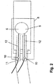
- the Figures 2 and 3 show the temperature sensor 5 from different views.
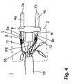
- the in Fig. 4 Connector 1 shown in more detail is connected to a vehicle charging cable of an electric or hybrid vehicle.
- the current contacts 4 and 4a, 4b are plug contacts 7a, 7b.
- the two plug contacts 7a, 7b are in Fig. 4 marked.
- the connector 1 has a connector housing 3 and the live current contacts 4a, 4b for a charging current of a battery of the electric or hybrid vehicle.
- two temperature sensors 5a, 5b are provided for charge control.
- additional current or temperature monitoring is also conceivable, with the actual charge regulation being able to be carried out by an external actual detection element.
- the terms regulation and monitoring here also include other terms such as control, protective measures and the like and are to be interpreted broadly here.
- Control lines or signal lines connected to the sensors 5a, 5b 50 shown in the figures are guided in the charging cable.
- the plug 1 is designed as a three-pole plug for a conductor L, a neutral conductor N and a protective conductor PE.
- This can be designed as a three-pole Schuko plug according to German standards with two lateral or opposite PE contacts and two front plug contacts 7a, 7b. However, this can also be designed as a three-pin plug 1 for a different country standard with three front plug contacts (not shown here).
- the figures therefore illustrate a connector 1 which is connected to a charging cable, in particular to a vehicle charging cable of an electric or hybrid vehicle, and a connector housing 3, as well as live current contacts 4a, 4b for a charging current, in particular a battery of the electric or hybrid vehicle , at least one temperature sensor 5a, 5b for charge control and / or charge monitoring being arranged in the connector housing 3.
- Each temperature sensor 5a, 5b consists of a sensor head 6 and sensor connection legs 12.
- the sensor head 6 is in direct contact with an area of one of the live plug contacts 4a, 4b.
- the connecting legs 12 are arranged parallel to the live plug contact 4a, 4b.
- the sensor head 6 is held by a shrink tube 8 in the area of the corresponding live plug contact 4a or 4b, as the figures show.
- the sensor head 6 is also pressed against the area of the live plug contact 7a, 7b in that a shrinkage process takes place.
- the shrinkage process takes place through the action of heat.
- the action of heat reduces the diameter of the shrink tube 8.
- the shrink tube 8 completely surrounds the area of the plug contact 7a or 7b and the sensor head 6, so that the temperature sensor 5 on the one hand is thermally conductive and mechanically connected to the plug contact 7a, 7b through the shrink tube and the temperature sensor 5 on the other hand is arranged in a type of heating chamber 9 formed by the shrink tube 8.
- the shrink tube 8 is so long that the sensor head 6 and the sensor connection legs 12 are essentially arranged in the shrink tube 8.
- the connecting legs 12 protrude slightly from the shrink tube 8.
- the sensor connection legs 12 are soldered directly to the sensor signal lines 50.
- the soldered connections 10 are in the Figures 1 and 2 marked.
- each sensor connection leg 12 is electrically insulated with a further, thinner shrink tube 11.
- a further, thinner shrink tube 11 is present.
- the thinner shrink tubes 11 are essentially arranged in the thicker shrink tube 8.
- a total of two temperature sensors 5a, 5b are arranged, the temperature sensor 5a being assigned to the plug contact 7a and the temperature sensor 5b being assigned to the plug contact 7b. Both temperature sensors 5a, 5b are electrically connected in series.
- Each shrink tube 11 consists of a transparent material.
- the diameter of the shrink tube 11 in the unshrunk state is approximately 4 to 8 mm.
- the diameter shrinks by about 20% to 50%.
- Each of the sensors 5a, 5b is designed as a thermocouple, in particular as an NTC thermistor.
- the plug 1 is a standardized mains plug for an alternating voltage network.
- the plug is a standardized mains plug for an alternating voltage network, a different plug type or a different charging voltage that is suitable for charging the battery of the electric car can also be used.
- the invention is therefore not limited to the example according to the figures.
- other sensors such as PTC sensors can be used.
Landscapes
- Engineering & Computer Science (AREA)
- Life Sciences & Earth Sciences (AREA)
- Sustainable Development (AREA)
- Sustainable Energy (AREA)
- Power Engineering (AREA)
- Transportation (AREA)
- Mechanical Engineering (AREA)
- Microelectronics & Electronic Packaging (AREA)
- Electric Propulsion And Braking For Vehicles (AREA)
- Details Of Connecting Devices For Male And Female Coupling (AREA)
- Secondary Cells (AREA)
Description
- Die Erfindung betrifft einen Stecker nach dem Oberbegriff des Anspruches 1.
- Bei Elektro- oder Hybridfahrzeugen wird die Batterie über ein Ladekabel geladen. Das Ladekabel ist mit einem Netzstecker versehen. Der Netzstecker kann an eine Haushaltssteckdose angeschlossen werden.
- Der Ladestrom wird häufig in Abhängigkeit einer Temperatur der Steckkontakte geregelt. Hierbei werden Temperatursensoren eingesetzt.
- Bekannte Laderegelungen durch Temperatursensoren haben oft den Nachteil, dass sie relativ träge sind. So kann es bis zu 20 Minuten dauern, bis ein Temperatur-Ist-Wert erfasst wird.
- Auch müssen am Stecker Änderungen vorgenommen werden, um die Temperatursensoren in diesem zu integrieren.
- Aus der
DE 10 2010 014 024 A1 ist ein Stecker der gattungsgemäßen Art bekannt, in dem ein Temperatursensor bzw. ein PTC- oder NTC-Sensor - integriert ist. Der Sensor ist so positioniert, dass er eine Temperatur nahe einer Verbindung zwischen den Kontaktsteckern und den Buchsen erfasst. Der Temperatursensor kann in einem Gehäuse im Spritzguss umspritzt sein.
- Der Erfindung liegt die Aufgabe zugrunde, einen Stecker der gattungsgemäßen Art zu schaffen, der eine schnelle Laderegelung unter bei geringen Herstellungskosten erlaubt.
-
WO 2017/137826 A1 offenbart einen Ladestecker für eine Fahrzeugbatterie. Dieser Ladestecker weist einen Sensor auf, der mit einem Schrumpfschlauch befestigt wird. Die OffenlegungsschriftDE 10 2014 111 831 A1 offenbart ein Steckverbinderteil mit Temperatursensoren. Dieses umfasst mehrere elektrische Kontaktelemente zum Führen von elektrischem Strom und mehrere Temperatursensoren, von denen jeder an einem zugeordneten Kontaktelement angeordnet ist. Das europäische PatentEP 2 991 082 B1 offenbart einen umspritzten Stecker in Schichtbauweise für Elektroautos, welcher mit wenigstens einem Temperatursensor ausgestattet ist. Die OffenlegungsschriftDE 10 2006 052 039 A1 offenbart einen Schaltschrank mit Temperaturüberwachung. Der Schaltschrank umfasst eine Schaltanlage mit mehreren Leitern und elektrisch verbundenen Modulen. Den Modulen können Temperatursensoren zugeordnet werden. - Diese Aufgabe wird durch einen Stecker mit dem im kennzeichnenden Teil des Anspruches 1 angegebenen Merkmale in Verbindung mit seinen Oberbegriffsmerkmalen gelöst.
- Die Erfindung beruht auf den Gedanken, den Temperatursensor direkt mit dem Stecker thermisch und mechanisch zu verbinden, um eine schnelle Temperaturerfassung zu ermöglichen. Dabei können handelsübliche Sensorelemente verwendet werden.
- Die Erfindung ist besonders vorteilhaft für Stecker, die mit einem Ladekabel und zwar mit einem Fahrzeugladekabel eines Elektro- oder Hybridfahrzeuges verbunden sind. Der Stecker hat ein Steckergehäuse sowie spannungsführende Stromkontakte für einen Ladestrom. Der Ladestrom lädt eine Batterie des Elektro- oder Hybridfahrzeuges. Im Steckergehäuse ist mindestens ein Temperatursensor für eine Laderegelung und/oder eine Ladeüberwachung angeordnet.
- Der nach der Erfindung verwendete Temperatursensor ist ein handelüblicher Sensor, der aus einem Sensorkopf und Sensoranschlussbeinen besteht. Der Sensorkopf kann in etwa eine Kugelform aufweisen.
- Der Sensorkopf steht in vorteilhafter Weise im direkten Kontakt mit einem Bereich eines der spannungsführenden Steckkontakte. Dadurch ist eine sehr schnelle Wärmeübertragung möglich. So kann es nur wenige Minuten dauern, bis ein Temperatur-Ist-Wert erfasst wird.
- Die Anschlussbeine sind parallel zum spannungsführenden Steckkontakt angeordnet. Dadurch ist eine platzsparende Sensoranordnung möglich.
- Der Sensorkopf wird erfindungsgemäß durch einen Schrumpfschlauch in dem Bereich eines der spannungsführenden Steckkontakte gehalten und gegen den Bereich eines der spannungsführenden Steckkontakte gedrückt.
- Der Sensorkopf wird mit einer geeigneten Kraft durch den Schrumpfungsprozess des Schrumpfschlauches gegen den spannungsführenden Steckkontakt gedrückt. Dadurch entsteht ohne das Erfordernis von Wärmeleitpaste ein guter Wärmekontakt zwischen Sensorkopf und spannungsführenden Steckkontakt.
- Der Schrumpfschlauch umgibt den Bereich des Steckkontaktes und den Sensorkopfes vollständig, so dass einerseits der Temperatursensor wärmeleittechnisch und mechanisch mit dem Steckkontakt durch den Schrumpfschlauch verbunden ist und der Temperatursensor andererseits in einer Art Wärmekammer, die durch den Schrumpfschlauch gebildet wird, angeordnet ist. Der Schrumpfschlauch wirkt wie ein thermischer Isolator, was eine schnelle Ist-Wert-Erfassung ermöglicht.
- Der erfindungsgemäße Stecker hat den Vorteil, dass einerseits keine Änderungen am Gehäuse des Steckers vorgenommen werden müssen und andererseits handelsübliche Sensoren ohne zusätzliche Elemente verwendet werden können.
- Außerdem wird durch die Erfindung eine ausreichende elektrische Isolation berücksichtigt. Im Stecker integrierte Sensoren müssen nämlich Normen erfüllen, die sicherstellen, dass zwischen den Netzspannung führenden Teilen und den Sensorleitungen eine ausreichende elektrische Isolation vorhanden ist.
- Die Erfindung beruht auf der Erkenntnis, dass zur Laderegelung bzw. Ladeüberwachung eine Temperatur der Kontakte eines Steckers dient. Je höher der Ladestrom ist, desto höher ist die Temperatur der Steckkontakte.
- Bei hohen Stromlasten bzw. hohen Ladeströmen erwärmen sich die Kontakte des Steckers. Der Gedanke ist, im nahen Bereich der Verbindung zwischen Kabel und Stecker die Temperatur durch einen erfindungsgemäßen Sensor zu überwachen.
- Durch den schnellen und effizienten Temperatur-Übertrag ist eine Regelung der Leistung bzw. des Stromes um ein vielfaches schneller als bekannte Lösungen.
- Als Temperatursensor kann jedes Bauteil eingesetzt werden, das zum Beispiel seinen Widerstand in Abhängigkeit der Temperatur verändert.
- Beispielsweise können Heißletter (NTC) verwendet werden. Diese verringern ihren Widerstand bei Temperaturerhöhung. Sie basieren auf Metalloxiden oder Halbleitern, Ein solches Bauteil wird auch Thermistor genannt.
- Einsetzbar sind auch Kaltleiter (PTC). Diese erhöhen ihren Widerstand bei Temperaturerhöhung.
- Zum Beispiel ist ein Sensor vom Typ NTCALUG01A von Vishay verwendet werden.
- Verwendbar sind auch Platin-Messwiderstände. Diese haben einen nahezu temperaturlinearen Widerstandsverlauf. Sie können für Temperaturen zwischen -200 °C und +850 °C eingesetzt werden.
- Denkbar ist auch die Anordnung von Silizium-Messwiderständen. Diese können im Temperaturbereich von -50 °C bis +150 °C eingesetzt werden.
- Grundsätzlich kann auch ein Keramik-Kaltleiter eingesetzt werden. Dieser weist bei einer materialspezifischen Temperatur einen starken Widerstandsanstieg auf.
- Als Temperatursensor können auch andere Bauteile verwendet werden, die direkt ein bearbeitbares elektrisches Signal liefern. Beispielsweise können integrierte Halbleiter-Temperatursensoren bzw. Festkörperschaltkreise genutzt werden, die einen zu ihrer Temperatur proportionalen Strom liefern.
- Alternativ kann auch ein Wärmefühler mit Schwingquarz als Messelement eingesetzt werden. Die Resonanzfrequenz des schwingenden Quarzes verändert sich abhängig von der Temperatur und kann sehr präzise gemessen werden.
- Stattdessen können genauso gut Thermoelemente verbaut werden. Diese wandeln eine Temperaturdifferenz durch den sogenannten Seebeck-Effekt in eine elektrische Spannung um.
- Nicht auszuschließen sind pyroelektrische Materialien. Diese ändern die Ladungsträgerdichte an ihrer Oberfläche bei Temperaturschwankungen durch Veränderung der spontanen Polarisation.
- In Frage kommen auch sogenannte Curie-Effekt-Temperatursensoren. Diese bestehen aus einem Dauermagneten, der unterhalb der Curie-Temperatur an ferromagnetischem Material haftet und oberhalb dieser Temperatur abfällt und dabei einen Schalter betätigt.
- Grundsätzlich ist die Verwendung von faseroptischen Temperatursensoren möglich. Sie beruhen auf dem sogenannten Raman-Effekt oder der temperaturabhängigen Änderung des Brechungsindex in Faser-Bragg-Gitter-Sensoren (FBGS).
- Es ist also eine Vielzahl von Temperatursensoren bzw. Wärmefühler, Temperaturfühler, Wärmesensoren und dergleichen möglich.
- Weitere vorteilhafte Ausgestaltungen der Erfindung sind in den Unteransprüchen gekennzeichnet.
- In einer vorteilhaften Weiterbildung des erfindungsgemäßen Steckers ist vorgesehen, dass der Schrumpfschlauch so lang ist, dass der Sensorkopf und die Sensoranschlussbeine in dem Schrumpfschlauch angeordnet sind. Dadurch wird einerseits der Sensorkopf gegen den Kontakt gedrückt, so dass ein guter Wärmekontakt entsteht, und andererseits die Anschlussbeine elektrisch isoliert und mechanisch geschützt.
- In dem erfindungsgemässen Stecker ist vorgesehen, dass die Sensoranschlussbeine mit Sensorsignalleitungen direkt verlötet sind. Dadurch ist eine platzsparende Anordnung möglich. Damit die Anschlussbeine des Sensors zusätzlich elektrisch isoliert sind, sowohl gegenseitig als auch gegenüber dem spannungsführenden Stecker ist weiterhin vorgesehen, dass jedes Sensoranschlussbein mit einem weiteren, dünneren Schrumpfschlauch elektrisch isoliert ist, so dass zwei dünne Schrumpfschläuche und ein dickerer Schrumpfschlauch vorhanden sind und die dünneren Schrumpfschläuche im Wesentlichen in dem dickeren Schrumpfschlauch angeordnet sind.
- Damit Isolierstecken und Normen eingehalten werden können, ist es vorteilhaft, wenn die dünneren Schrumpfschläuche aus dem dickeren Schrumpfschlauch ein Stück herausragen.
- Bei einer vorteilhaften Ausführung der Erfindung sind insgesamt zwei Temperatursensoren angeordnet, wobei jeweils ein Temperatursensor einem Steckkontakt zugeordnet ist. Dadurch werden Abweichungen bei unterschiedlichen Kontaktkräften der Steckkontakte kompensiert und so die Messgenauigkeit erhöht.
- Eine andere vorteilhafte Ausführung der Erfindung ist dadurch gekennzeichnet, dass beide Temperatursensoren in Reihe geschaltet sind. Aus dem Reihewiderstand kann eine genauere Messung und eine einfache Auswertung erreicht werden.
- Um eine Qualitätskontrolle zu erleichtern und die Sensorposition überprüfen zu können Ist es von Vorteil, wenn jeder Schrumpfschlauch aus einem transparenten Material besteht.
- Bei einer anderen vorteilhaften Ausführung der Erfindung ist der Sensor als Thermoelement, insbesondere als NTC-Thermistor ausgeführt ist. Dieser erlaubt eine genaue Messung bei geringen Kosten.
- Für Elektroautos wird bevorzugter Weise ein genormter Netzstecker für ein Wechselspannungsstromnetz eingesetzt.
- Für Elektroautos wird bevorzugter Weise ein genormter Netzstecker für ein Wechselspannungsstromnetz eingesetzt.
- Ein Ausführungsbeispiel wird anhand der Zeichnungen näher erläutert, wobei weitere vorteilhafte Weiterbildungen der Erfindung und Vorteile derselben beschrieben sind.
- Es zeigen:
- Fig. 1
- eine erste schematische Darstellung einer Ausführungsform des erfindungsgemäßen Steckers von der Seite gesehen,
- Fig. 2
- eine zweite schematische Darstellung des erfindungsgemäßen Steckers von oben gesehen,
- Fig. 3
- eine dritte schematische Darstellung des erfindungsgemäßen Steckers von einer Stirnseite gesehen, und
- Fig. 4
- eine perspektivische Darstellung des erfindungsgemäßen Steckers,
-
Fig. 1 zeigt einen Steckkontakt 4 eines Steckers zur Verwendung in einem deutschen Stromnetz. An dem Steckkontakt 4 ist ein Temperatursensor 5 angeordnet. DieFiguren 2 und3 zeigen den Temperatursensor 5 aus verschiedenen Ansichten. - Der in
Fig. 4 näher gezeigte Stecker 1 ist mit einem Fahrzeugladekabel eines Elektro- oder Hybridfahrzeuges verbunden. Die Stromkontakte 4 bzw. 4a, 4b sind Steckkontakte 7a, 7b. Die beiden Steckkontakte 7a, 7b sind inFig. 4 gekennzeichnet. Der Stecker 1 weist ein Steckergehäuse 3 sowie die spannungsführende Stromkontakte 4a, 4b für einen Ladestrom einer Batterie des Elektro- oder Hybridfahrzeuges auf. Im Steckergehäuse 3 sind zwei Temperatursensoren 5a, 5b für eine Laderegelung vorgesehen. Anstelle einer Regelung ist auch eine zusätzliche Strom- bzw. Temperaturüberwachung denkbar, wobei die eigentliche Laderegelung durch ein externes Ist-Erfassungselement erfolgen könnte. Die Begriffe Regelung und Überwachung umfassen hier auch andere Begriffe, wie Steuerung, Schutzmaßnahmen und dergleichen und sind hier weit auszulegen. - Mit den Sensoren 5a, 5b verbundene Steuerleitungen bzw. Signalleitungen 50, die in den Figuren gezeigt sind, werden im Ladekabel geführt.
- Der Stecker 1 ist als dreipoliger Stecker für einen Leiter L, einen Neutralleiter N und einen Schutzleiter PE ausgelegt. Dieser kann als dreipoliger Schukostecker nach deutscher Norm mit zwei seitlichen bzw. gegenüberliegenden PE-Kontakten und zwei vorderen Steckkontakten 7a, 7b konzipiert sein. Dieser kann aber auch als dreipoliger Stecker 1 für eine andere Ländernorm mit drei vorderen Steckkontakten ausgeführt sein (hier nicht gezeigt).
- Die Figuren veranschaulichen also einen Stecker 1, der mit einem Ladekabel, insbesondere mit einem Fahrzeugladekabel eines Elektro- oder Hybridfahrzeuges verbunden ist, und ein Steckergehäuse 3, sowie spannungsführende Stromkontakte 4a, 4b für einen Ladestrom, insbesondere einer Batterie des Elektro- oder Hybridfahrzeuges, umfasst, wobei im Steckergehäuse 3 mindestens ein Temperatursensor 5a, 5b für eine Laderegelung und/oder eine Ladeüberwachung angeordnet ist.
- Jeder Temperatursensor 5a, 5b besteht aus einem Sensorkopf 6 und Sensoranschlussbeinen 12. Der Sensorkopf 6 steht im direkten Kontakt mit einem Bereich eines der spannungsführenden Steckkontakte 4a, 4b. Die Anschlussbeine 12 sind parallel zum spannungsführenden Steckkontakt 4a, 4b angeordnet. Der Sensorkopf 6 wird durch einen Schrumpfschlauch 8 in dem Bereich des entsprechenden spannungsführenden Steckkontaktes 4a bzw. 4b gehalten, wie die Figuren zeigen. Der Sensorkopf 6 wird außerdem gegen den Bereich des spannungsführenden Steckkontaktes 7a, 7b gedrückt, indem ein Schrumpfungsprozess stattfindet. Der Schrumpfungsprozess erfolgt durch Wärmeeinwirkung. Durch die Wärmeeinwirkung verringert sich der Durchmesser des Schrumpfschlauches 8. Der Schrumpfschlauch 8 umgibt vollständig den Bereich des Steckkontaktes 7a bzw. 7b und den Sensorkopfes 6, so dass der Temperatursensor 5 einerseits wärmeleittechnisch und mechanisch mit dem Steckkontakt 7a, 7b durch den Schrumpfschlauch verbunden ist und der Temperatursensor 5 andererseits in einer Art Wärmekammer 9, die durch den Schrumpfschlauch 8 gebildet wird, angeordnet ist.
- Wie die
Figuren 1 und2 zeigen, ist der Schrumpfschlauch 8 so lang, dass der Sensorkopf 6 und die Sensoranschlussbeine 12 in dem Schrumpfschlauch 8 im Wesentlichen angeordnet sind. Hierbei ragen die Anschlussbeine 12 leicht aus dem Schrumpfschlauch 8 heraus. - Die Sensoranschlussbeine 12 sind mit den Sensorsignalleitungen 50 direkt verlötet. Die Lötverbindungen 10 sind in den
Figuren 1 und2 gekennzeichnet. - Wie außerdem die
Figuren 1 und2 zeigen, ist jedes Sensoranschlussbein 12 mit einem weiteren, dünneren Schrumpfschlauch 11 elektrisch isoliert. Somit sind zwei dünne Schrumpfschläuche 11 und ein dickerer Schrumpfschlauch 8 vorhanden. Die dünneren Schrumpfschläuche 11 sind im Wesentlichen in dem dickeren Schrumpfschlauch 8 angeordnet. - Wie die
Fig. 4 zeigt, sind insgesamt zwei Temperatursensoren 5a, 5b angeordnet sind, wobei jeweils der Temperatursensor 5a dem Steckkontakt 7a und der Temperatursensor 5b dem Steckkontakt 7b zugeordnet ist. Beide Temperatursensoren 5a, 5b sind elektrisch In Reihe geschaltet. - Jeder Schrumpfschlauch 11 besteht einem transparenten Material. Der Durchmesser des Schrumpfschlauches 11 beträgt im ungeschrumpften Zustand etwa 4 bis 8 mm. Der Durchmesser schrumpft um etwa 20% bis 50%. Jeder der Sensoren 5a, 5b ist als Thermoelement, insbesondere als NTC-Thermistor ausgeführt.
- Der Stecker 1 ist ein genormter Netzstecker für ein Wechselspannungsstromnetz.
- Zwar ist der Stecker ein genormter Netzstecker für ein Wechselspannungsstromnetz, jedoch kann auch ein anderer Steckertyp bzw. eine andere Ladespannung verwendet werden, die geeignet ist die Batterie des Elektroautos zu laden.
- Die Erfindung ist also nicht auf das Beispiel nach den Figuren beschränkt. So können z.B. andere Sensoren, wie PTC- Sensoren, verwendet werden.
-
- 1
- Stecker
- 2
- Fahrzeugladekabel
- 3
- Steckergehäuse
- 4a
- Stromkontakt
- 4b
- Stromkontakt
- 5a
- Temperatursensor
- 5b
- Temperatursensor
- 6
- Sensorkopf
- 7a
- Steckkontakt
- 7b
- Steckkontakt
- 8
- Schrumpfschlauch
- 9
- Wärmekammer
- 10
- Lötverbindungen
- 11
- Schrumpfschlauch
- 12
- Sensoranschlussbeine
- 50
- Signalleitungen
Claims (8)
- Stecker (1), der mit einem Ladekabel, insbesondere mit einem Fahrzeugladekabel eines Elektro- oder Hybridfahrzeuges verbindbar ist, und ein Steckergehäuse (3), sowie spannungsführende Stromkontakte (4a, 4b) für einen Ladestrom, insbesondere einer Batterie des Elektro- oder Hybridfahrzeuges, umfasst, wobei im Steckergehäuse (3) mindestens ein Temperatursensor (5a, 5b) für eine Laderegelung und/oder eine Ladeüberwachung angeordnet ist, wobei der Temperatursensor (5a, 5b) aus einem Sensorkopf (6) und Sensoranschlussbeinen (12) besteht, wobei ferner Sensorsignalleitungen (50) vorgesehen sind und der Sensorkopf (6) im direktem Kontakt mit einem Bereich eines spannungsführenden Steckkontaktes (7a, 7b) steht und die Anschlussbeine (12) parallel zum spannungsführenden Steckkontakt (7a, 7b) angeordnet sind, und dass der Sensorkopf (6) durch einen Schrumpfschlauch (8) in dem Bereich des entsprechenden spannungsführenden Steckkontaktes (7a, 7b) gehalten wird und gegen den Bereich des spannungsführenden Steckkontaktes (7a, 7b) gedrückt wird, indem ein Schrumpfungsprozess stattfindet, wobei der Schrumpfschlauch (8) den Bereich des Steckkontaktes (7a, 7b) und den Sensorkopfes (6) vollständig umgibt, so dass der Temperatursensor (5a, 5b) einerseits wärmeleittechnisch und mechanisch mit dem Steckkontakt (7a, 7b) durch den Schrumpfschlauch (8) verbunden ist und der Temperatursensor (5a, 5b) andererseits in einer Art Wärmekammer (9), die durch den Schrumpfschlauch (8) gebildet wird, angeordnet ist dadurch gekennzeichnet, dass die Sensoranschlussbeine (12) mit Sensorsignalleitungen (50) direkt verlötet sind und jedes Sensoranschlussbein mit einem weiteren, dünneren Schrumpfschlauch (11) elektrisch isoliert ist, sodass zwei dünne Schrumpfschläuche (11) und ein dickerer Schrumpfschlauch (8) vorhanden sind und die dünneren Schrumpfschläuche (11) im Wesentlichen in dem dickeren Schrumpfschlauch (8) angeordnet sind.
- Stecker nach Anspruch 1, dadurch gekennzeichnet, dass der Schrumpfschlauch so lang ist, dass der Sensorkopf (6) und die Sensoranschlussbeine (12) in dem Schrumpfschlauch angeordnet sind.
- Stecker nach Anspruch 1, dadurch gekennzeichnet, dass die dünneren Schrumpfschläuche (8) aus dem dickerem Schrumpfschlauch (11) ein Stück herausragen.
- Stecker nach einem der vorhergehenden Ansprüche, dadurch gekennzeichnet, dass insgesamt zwei Temperatursensoren (5a, 5b) angeordnet sind, wobei jeweils ein Temperatursensor (5a, 5b) einem Steckkontakt (7a, 7b) zugeordnet ist.
- Stecker nach Anspruch 4, dadurch gekennzeichnet, dass beide Temperatursensoren (5a, 5b) in Reihe geschaltet sind.
- Stecker nach einem der vorhergehenden Ansprüche, dadurch gekennzeichnet, dass jeder Schrumpfschlauch (8) aus einem transparenten Material besteht.
- Stecker nach einem der vorhergehenden Ansprüche, dadurch gekennzeichnet, dass der Sensor (5a, 5b) als Thermoelement, insbesondere als NTC-Thermistor ausgeführt ist.
- Stecker nach einem der vorhergehenden Ansprüche, gekennzeichnet durch eine Ausführung als genormter Netzstecker für ein Wechselspannungsstromnetz.
Applications Claiming Priority (2)
| Application Number | Priority Date | Filing Date | Title |
|---|---|---|---|
| DE202016103030.7U DE202016103030U1 (de) | 2016-06-07 | 2016-06-07 | Stecker, insbesondere mit einem Fahrzeugladekabel eines Elektro- oder Hybridfahrzeuges |
| PCT/DE2017/100460 WO2017211349A1 (de) | 2016-06-07 | 2017-05-30 | Stecker, insbesondere mit einem fahrzeugladekabel eines elektro-oder hybridfahrzeuges |
Publications (2)
| Publication Number | Publication Date |
|---|---|
| EP3463969A1 EP3463969A1 (de) | 2019-04-10 |
| EP3463969B1 true EP3463969B1 (de) | 2021-12-22 |
Family
ID=59383387
Family Applications (1)
| Application Number | Title | Priority Date | Filing Date |
|---|---|---|---|
| EP17742364.7A Active EP3463969B1 (de) | 2016-06-07 | 2017-05-30 | Stecker, insbesondere mit einem fahrzeugladekabel eines elektro- oder hybridfahrzeuges |
Country Status (4)
| Country | Link |
|---|---|
| EP (1) | EP3463969B1 (de) |
| DE (1) | DE202016103030U1 (de) |
| HU (1) | HUE058281T2 (de) |
| WO (1) | WO2017211349A1 (de) |
Families Citing this family (6)
| Publication number | Priority date | Publication date | Assignee | Title |
|---|---|---|---|---|
| DE102017222808A1 (de) * | 2017-12-14 | 2019-06-19 | Phoenix Contact E-Mobility Gmbh | Lastkontaktmodul und Ladestecker |
| DE202018003420U1 (de) | 2018-07-23 | 2018-08-16 | Heraeus Sensor Technology Gmbh | Steckverbinder mit Flip-Chip Messelement |
| DE102019200870A1 (de) | 2019-01-24 | 2020-07-30 | Audi Ag | Ladekabel |
| DE102019202912A1 (de) | 2019-03-05 | 2020-09-10 | Zf Friedrichshafen Ag | Verschaltungsanordnung für einen Stator, Temperatursensoreinrichtung und System zum Erfassen einer Temperatur |
| JP7017591B2 (ja) * | 2020-02-04 | 2022-02-08 | 矢崎総業株式会社 | 端子付電線及びセンサ固定方法 |
| DE102022124719A1 (de) * | 2022-09-26 | 2024-03-28 | Kiekert Aktiengesellschaft | Ladesteckverbinder für Elektro- und Hybridfahrzeuge |
Citations (1)
| Publication number | Priority date | Publication date | Assignee | Title |
|---|---|---|---|---|
| DE102006052039A1 (de) * | 2006-10-30 | 2008-05-08 | Siemens Ag | Schaltschrank mit Temperaturüberwachung |
Family Cites Families (4)
| Publication number | Priority date | Publication date | Assignee | Title |
|---|---|---|---|---|
| DE102010014024A1 (de) | 2010-04-05 | 2011-10-06 | Axel R. Hidde | Verpackung eines Mittels mit angeformtem Werkzeug |
| DE102014111831A1 (de) * | 2014-08-19 | 2016-02-25 | Phoenix Contact E-Mobility Gmbh | Steckverbinderteil mit Temperatursensoren |
| DE102014012576A1 (de) * | 2014-08-29 | 2016-03-03 | Heidelberger Druckmaschinen Ag | Umspritzer Stecker in Schichtbauweise für Elektroautos |
| DE102016001572A1 (de) * | 2016-02-11 | 2017-08-17 | Sumitomo Wiring Systems, Ltd. | Ladeverbinder, Anschlusspassstück und Verfahren zum Fixieren eines Sensors an einem Anschlusspassstück |
-
2016
- 2016-06-07 DE DE202016103030.7U patent/DE202016103030U1/de not_active Expired - Lifetime
-
2017
- 2017-05-30 WO PCT/DE2017/100460 patent/WO2017211349A1/de not_active Ceased
- 2017-05-30 HU HUE17742364A patent/HUE058281T2/hu unknown
- 2017-05-30 EP EP17742364.7A patent/EP3463969B1/de active Active
Patent Citations (1)
| Publication number | Priority date | Publication date | Assignee | Title |
|---|---|---|---|---|
| DE102006052039A1 (de) * | 2006-10-30 | 2008-05-08 | Siemens Ag | Schaltschrank mit Temperaturüberwachung |
Also Published As
| Publication number | Publication date |
|---|---|
| DE202016103030U1 (de) | 2017-09-09 |
| WO2017211349A1 (de) | 2017-12-14 |
| EP3463969A1 (de) | 2019-04-10 |
| HUE058281T2 (hu) | 2022-07-28 |
Similar Documents
| Publication | Publication Date | Title |
|---|---|---|
| EP3463969B1 (de) | Stecker, insbesondere mit einem fahrzeugladekabel eines elektro- oder hybridfahrzeuges | |
| DE102015004313A1 (de) | Stecker, insbesondere mit einem Fahrzeugladekabel eines Elektro- oder Hybridfahrzeuges | |
| EP3178136B1 (de) | Steckverbinderteil mit einer temperatursensoreinrichtung | |
| EP3183781B1 (de) | Steckverbinderteil mit temperatursensoren | |
| DE102018200886B3 (de) | Verfahren zum Überwachen eines elektrischen Stromflusses | |
| DE102016107401A1 (de) | Steckvorrichtung mit Temperaturerfassung | |
| DE102014102991B3 (de) | Steckverbinder mit Sensoranordnung | |
| DE102018009749B4 (de) | Elektrisches Kontaktelement für einen Steckverbinder, Steckverbinder und Verfahren zum Überwachen eines elektrischen Stromflusses | |
| WO2012069205A1 (de) | Elektrischer steckverbinder für thermoelemente und verfahren zu dessen herstellung | |
| DE102018204271A1 (de) | Anordnung zur Erfassung der Temperatur und Kontaktanordnung mit einer solchen Anordnung | |
| DE4336564C2 (de) | Temperaturwächter | |
| DE102011111081A1 (de) | Batteriesensor | |
| DE102011004353B4 (de) | Leiterplatte mit einer Überwachungselektronik zur Überwachung von Batteriezellen, sowie damit ausgestatteter elektrischer Energiespeicher | |
| DE202015106844U1 (de) | Stecker mit einem Fahrzeugladekabel eines Elektro- oder Hybridfahrzeuges | |
| DE102015218290A1 (de) | Vorrichtung für Hoch-/Mittel-/Niederspannungsstrommessung | |
| WO2002013330A1 (de) | Elektrischer steckverbinder | |
| DE102015104170B4 (de) | Anschlusssteckvorrichtung | |
| DE102019109393B4 (de) | Leiterplattendurchführung und elektrisch leitender pin zum führen in einer leiterplattendurchführung | |
| DE102021107218A1 (de) | Vorrichtung zur Temperaturmessung und Vorrichtung zur Stromermittlung | |
| DE102019113607A1 (de) | Ladestecker für ein elektrofahrzeug | |
| EP2233353B1 (de) | Zigarettenanzünder, insbesondere für Kraftfahrzeuge | |
| DE102013219092B4 (de) | Anordnung eines Temperatursensors mit einer elektrisch isolierenden Umhüllung | |
| DE202015009850U1 (de) | Stecker für ein Fahrzeugladekabel eines Elektro- oder Hybridfahrzeuges | |
| DE102022134335A1 (de) | Steckverbinderteil für ein Ladesystem zum Aufladen eines Elektrofahrzeugs | |
| DE102013219094B4 (de) | Anordnung eines Temperatursensors mit einer elektrisch und thermisch isolierenden Umhüllung |
Legal Events
| Date | Code | Title | Description |
|---|---|---|---|
| STAA | Information on the status of an ep patent application or granted ep patent |
Free format text: STATUS: UNKNOWN |
|
| STAA | Information on the status of an ep patent application or granted ep patent |
Free format text: STATUS: THE INTERNATIONAL PUBLICATION HAS BEEN MADE |
|
| PUAI | Public reference made under article 153(3) epc to a published international application that has entered the european phase |
Free format text: ORIGINAL CODE: 0009012 |
|
| STAA | Information on the status of an ep patent application or granted ep patent |
Free format text: STATUS: REQUEST FOR EXAMINATION WAS MADE |
|
| 17P | Request for examination filed |
Effective date: 20190104 |
|
| AK | Designated contracting states |
Kind code of ref document: A1 Designated state(s): AL AT BE BG CH CY CZ DE DK EE ES FI FR GB GR HR HU IE IS IT LI LT LU LV MC MK MT NL NO PL PT RO RS SE SI SK SM TR |
|
| AX | Request for extension of the european patent |
Extension state: BA ME |
|
| DAV | Request for validation of the european patent (deleted) | ||
| DAX | Request for extension of the european patent (deleted) | ||
| STAA | Information on the status of an ep patent application or granted ep patent |
Free format text: STATUS: EXAMINATION IS IN PROGRESS |
|
| 17Q | First examination report despatched |
Effective date: 20200221 |
|
| REG | Reference to a national code |
Ref country code: DE Ref legal event code: R079 Ref document number: 502017012303 Country of ref document: DE Free format text: PREVIOUS MAIN CLASS: B60L0011180000 Ipc: H01R0004720000 |
|
| RIC1 | Information provided on ipc code assigned before grant |
Ipc: H01R 13/66 20060101ALI20200825BHEP Ipc: H01R 4/72 20060101AFI20200825BHEP Ipc: B60L 50/60 20190101ALI20200825BHEP |
|
| GRAP | Despatch of communication of intention to grant a patent |
Free format text: ORIGINAL CODE: EPIDOSNIGR1 |
|
| STAA | Information on the status of an ep patent application or granted ep patent |
Free format text: STATUS: GRANT OF PATENT IS INTENDED |
|
| INTG | Intention to grant announced |
Effective date: 20210917 |
|
| GRAS | Grant fee paid |
Free format text: ORIGINAL CODE: EPIDOSNIGR3 |
|
| GRAA | (expected) grant |
Free format text: ORIGINAL CODE: 0009210 |
|
| STAA | Information on the status of an ep patent application or granted ep patent |
Free format text: STATUS: THE PATENT HAS BEEN GRANTED |
|
| AK | Designated contracting states |
Kind code of ref document: B1 Designated state(s): AL AT BE BG CH CY CZ DE DK EE ES FI FR GB GR HR HU IE IS IT LI LT LU LV MC MK MT NL NO PL PT RO RS SE SI SK SM TR |
|
| REG | Reference to a national code |
Ref country code: GB Ref legal event code: FG4D Free format text: NOT ENGLISH |
|
| REG | Reference to a national code |
Ref country code: CH Ref legal event code: EP |
|
| REG | Reference to a national code |
Ref country code: DE Ref legal event code: R096 Ref document number: 502017012303 Country of ref document: DE |
|
| REG | Reference to a national code |
Ref country code: AT Ref legal event code: REF Ref document number: 1457675 Country of ref document: AT Kind code of ref document: T Effective date: 20220115 |
|
| REG | Reference to a national code |
Ref country code: IE Ref legal event code: FG4D Free format text: LANGUAGE OF EP DOCUMENT: GERMAN |
|
| REG | Reference to a national code |
Ref country code: LT Ref legal event code: MG9D |
|
| PG25 | Lapsed in a contracting state [announced via postgrant information from national office to epo] |
Ref country code: RS Free format text: LAPSE BECAUSE OF FAILURE TO SUBMIT A TRANSLATION OF THE DESCRIPTION OR TO PAY THE FEE WITHIN THE PRESCRIBED TIME-LIMIT Effective date: 20211222 Ref country code: LT Free format text: LAPSE BECAUSE OF FAILURE TO SUBMIT A TRANSLATION OF THE DESCRIPTION OR TO PAY THE FEE WITHIN THE PRESCRIBED TIME-LIMIT Effective date: 20211222 Ref country code: FI Free format text: LAPSE BECAUSE OF FAILURE TO SUBMIT A TRANSLATION OF THE DESCRIPTION OR TO PAY THE FEE WITHIN THE PRESCRIBED TIME-LIMIT Effective date: 20211222 Ref country code: BG Free format text: LAPSE BECAUSE OF FAILURE TO SUBMIT A TRANSLATION OF THE DESCRIPTION OR TO PAY THE FEE WITHIN THE PRESCRIBED TIME-LIMIT Effective date: 20220322 |
|
| REG | Reference to a national code |
Ref country code: NL Ref legal event code: MP Effective date: 20211222 |
|
| PG25 | Lapsed in a contracting state [announced via postgrant information from national office to epo] |
Ref country code: SE Free format text: LAPSE BECAUSE OF FAILURE TO SUBMIT A TRANSLATION OF THE DESCRIPTION OR TO PAY THE FEE WITHIN THE PRESCRIBED TIME-LIMIT Effective date: 20211222 Ref country code: NO Free format text: LAPSE BECAUSE OF FAILURE TO SUBMIT A TRANSLATION OF THE DESCRIPTION OR TO PAY THE FEE WITHIN THE PRESCRIBED TIME-LIMIT Effective date: 20220322 Ref country code: LV Free format text: LAPSE BECAUSE OF FAILURE TO SUBMIT A TRANSLATION OF THE DESCRIPTION OR TO PAY THE FEE WITHIN THE PRESCRIBED TIME-LIMIT Effective date: 20211222 Ref country code: HR Free format text: LAPSE BECAUSE OF FAILURE TO SUBMIT A TRANSLATION OF THE DESCRIPTION OR TO PAY THE FEE WITHIN THE PRESCRIBED TIME-LIMIT Effective date: 20211222 Ref country code: GR Free format text: LAPSE BECAUSE OF FAILURE TO SUBMIT A TRANSLATION OF THE DESCRIPTION OR TO PAY THE FEE WITHIN THE PRESCRIBED TIME-LIMIT Effective date: 20220323 |
|
| PG25 | Lapsed in a contracting state [announced via postgrant information from national office to epo] |
Ref country code: NL Free format text: LAPSE BECAUSE OF FAILURE TO SUBMIT A TRANSLATION OF THE DESCRIPTION OR TO PAY THE FEE WITHIN THE PRESCRIBED TIME-LIMIT Effective date: 20211222 |
|
| REG | Reference to a national code |
Ref country code: HU Ref legal event code: AG4A Ref document number: E058281 Country of ref document: HU |
|
| PG25 | Lapsed in a contracting state [announced via postgrant information from national office to epo] |
Ref country code: SM Free format text: LAPSE BECAUSE OF FAILURE TO SUBMIT A TRANSLATION OF THE DESCRIPTION OR TO PAY THE FEE WITHIN THE PRESCRIBED TIME-LIMIT Effective date: 20211222 Ref country code: SK Free format text: LAPSE BECAUSE OF FAILURE TO SUBMIT A TRANSLATION OF THE DESCRIPTION OR TO PAY THE FEE WITHIN THE PRESCRIBED TIME-LIMIT Effective date: 20211222 Ref country code: RO Free format text: LAPSE BECAUSE OF FAILURE TO SUBMIT A TRANSLATION OF THE DESCRIPTION OR TO PAY THE FEE WITHIN THE PRESCRIBED TIME-LIMIT Effective date: 20211222 Ref country code: PT Free format text: LAPSE BECAUSE OF FAILURE TO SUBMIT A TRANSLATION OF THE DESCRIPTION OR TO PAY THE FEE WITHIN THE PRESCRIBED TIME-LIMIT Effective date: 20220422 Ref country code: ES Free format text: LAPSE BECAUSE OF FAILURE TO SUBMIT A TRANSLATION OF THE DESCRIPTION OR TO PAY THE FEE WITHIN THE PRESCRIBED TIME-LIMIT Effective date: 20211222 Ref country code: EE Free format text: LAPSE BECAUSE OF FAILURE TO SUBMIT A TRANSLATION OF THE DESCRIPTION OR TO PAY THE FEE WITHIN THE PRESCRIBED TIME-LIMIT Effective date: 20211222 Ref country code: CZ Free format text: LAPSE BECAUSE OF FAILURE TO SUBMIT A TRANSLATION OF THE DESCRIPTION OR TO PAY THE FEE WITHIN THE PRESCRIBED TIME-LIMIT Effective date: 20211222 |
|
| PG25 | Lapsed in a contracting state [announced via postgrant information from national office to epo] |
Ref country code: PL Free format text: LAPSE BECAUSE OF FAILURE TO SUBMIT A TRANSLATION OF THE DESCRIPTION OR TO PAY THE FEE WITHIN THE PRESCRIBED TIME-LIMIT Effective date: 20211222 |
|
| REG | Reference to a national code |
Ref country code: DE Ref legal event code: R097 Ref document number: 502017012303 Country of ref document: DE |
|
| PG25 | Lapsed in a contracting state [announced via postgrant information from national office to epo] |
Ref country code: IS Free format text: LAPSE BECAUSE OF FAILURE TO SUBMIT A TRANSLATION OF THE DESCRIPTION OR TO PAY THE FEE WITHIN THE PRESCRIBED TIME-LIMIT Effective date: 20220422 |
|
| PLBE | No opposition filed within time limit |
Free format text: ORIGINAL CODE: 0009261 |
|
| STAA | Information on the status of an ep patent application or granted ep patent |
Free format text: STATUS: NO OPPOSITION FILED WITHIN TIME LIMIT |
|
| PG25 | Lapsed in a contracting state [announced via postgrant information from national office to epo] |
Ref country code: DK Free format text: LAPSE BECAUSE OF FAILURE TO SUBMIT A TRANSLATION OF THE DESCRIPTION OR TO PAY THE FEE WITHIN THE PRESCRIBED TIME-LIMIT Effective date: 20211222 Ref country code: AL Free format text: LAPSE BECAUSE OF FAILURE TO SUBMIT A TRANSLATION OF THE DESCRIPTION OR TO PAY THE FEE WITHIN THE PRESCRIBED TIME-LIMIT Effective date: 20211222 |
|
| 26N | No opposition filed |
Effective date: 20220923 |
|
| REG | Reference to a national code |
Ref country code: CH Ref legal event code: PL |
|
| REG | Reference to a national code |
Ref country code: BE Ref legal event code: MM Effective date: 20220531 |
|
| GBPC | Gb: european patent ceased through non-payment of renewal fee |
Effective date: 20220530 |
|
| PG25 | Lapsed in a contracting state [announced via postgrant information from national office to epo] |
Ref country code: MC Free format text: LAPSE BECAUSE OF FAILURE TO SUBMIT A TRANSLATION OF THE DESCRIPTION OR TO PAY THE FEE WITHIN THE PRESCRIBED TIME-LIMIT Effective date: 20211222 Ref country code: LU Free format text: LAPSE BECAUSE OF NON-PAYMENT OF DUE FEES Effective date: 20220530 Ref country code: LI Free format text: LAPSE BECAUSE OF NON-PAYMENT OF DUE FEES Effective date: 20220531 Ref country code: CH Free format text: LAPSE BECAUSE OF NON-PAYMENT OF DUE FEES Effective date: 20220531 |
|
| PG25 | Lapsed in a contracting state [announced via postgrant information from national office to epo] |
Ref country code: SI Free format text: LAPSE BECAUSE OF FAILURE TO SUBMIT A TRANSLATION OF THE DESCRIPTION OR TO PAY THE FEE WITHIN THE PRESCRIBED TIME-LIMIT Effective date: 20211222 |
|
| PG25 | Lapsed in a contracting state [announced via postgrant information from national office to epo] |
Ref country code: IE Free format text: LAPSE BECAUSE OF NON-PAYMENT OF DUE FEES Effective date: 20220530 Ref country code: FR Free format text: LAPSE BECAUSE OF NON-PAYMENT OF DUE FEES Effective date: 20220531 |
|
| PG25 | Lapsed in a contracting state [announced via postgrant information from national office to epo] |
Ref country code: IT Free format text: LAPSE BECAUSE OF FAILURE TO SUBMIT A TRANSLATION OF THE DESCRIPTION OR TO PAY THE FEE WITHIN THE PRESCRIBED TIME-LIMIT Effective date: 20211222 Ref country code: GB Free format text: LAPSE BECAUSE OF NON-PAYMENT OF DUE FEES Effective date: 20220530 Ref country code: BE Free format text: LAPSE BECAUSE OF NON-PAYMENT OF DUE FEES Effective date: 20220531 |
|
| REG | Reference to a national code |
Ref country code: AT Ref legal event code: MM01 Ref document number: 1457675 Country of ref document: AT Kind code of ref document: T Effective date: 20220530 |
|
| PG25 | Lapsed in a contracting state [announced via postgrant information from national office to epo] |
Ref country code: AT Free format text: LAPSE BECAUSE OF NON-PAYMENT OF DUE FEES Effective date: 20220530 |
|
| PG25 | Lapsed in a contracting state [announced via postgrant information from national office to epo] |
Ref country code: MK Free format text: LAPSE BECAUSE OF FAILURE TO SUBMIT A TRANSLATION OF THE DESCRIPTION OR TO PAY THE FEE WITHIN THE PRESCRIBED TIME-LIMIT Effective date: 20211222 Ref country code: CY Free format text: LAPSE BECAUSE OF FAILURE TO SUBMIT A TRANSLATION OF THE DESCRIPTION OR TO PAY THE FEE WITHIN THE PRESCRIBED TIME-LIMIT Effective date: 20211222 |
|
| PG25 | Lapsed in a contracting state [announced via postgrant information from national office to epo] |
Ref country code: MT Free format text: LAPSE BECAUSE OF FAILURE TO SUBMIT A TRANSLATION OF THE DESCRIPTION OR TO PAY THE FEE WITHIN THE PRESCRIBED TIME-LIMIT Effective date: 20211222 |
|
| PGFP | Annual fee paid to national office [announced via postgrant information from national office to epo] |
Ref country code: DE Payment date: 20250531 Year of fee payment: 9 |
|
| PGFP | Annual fee paid to national office [announced via postgrant information from national office to epo] |
Ref country code: HU Payment date: 20250604 Year of fee payment: 9 |
|
| PG25 | Lapsed in a contracting state [announced via postgrant information from national office to epo] |
Ref country code: TR Free format text: LAPSE BECAUSE OF FAILURE TO SUBMIT A TRANSLATION OF THE DESCRIPTION OR TO PAY THE FEE WITHIN THE PRESCRIBED TIME-LIMIT Effective date: 20211222 |