EP3325748B1 - Élément de porte muni d'un dispositif amortisseur pilotable - Google Patents
Élément de porte muni d'un dispositif amortisseur pilotable Download PDFInfo
- Publication number
- EP3325748B1 EP3325748B1 EP16751508.9A EP16751508A EP3325748B1 EP 3325748 B1 EP3325748 B1 EP 3325748B1 EP 16751508 A EP16751508 A EP 16751508A EP 3325748 B1 EP3325748 B1 EP 3325748B1
- Authority
- EP
- European Patent Office
- Prior art keywords
- door
- damping
- closing
- speed
- damper device
- Prior art date
- Legal status (The legal status is an assumption and is not a legal conclusion. Google has not performed a legal analysis and makes no representation as to the accuracy of the status listed.)
- Active
Links
Images

Classifications
-
- E—FIXED CONSTRUCTIONS
- E05—LOCKS; KEYS; WINDOW OR DOOR FITTINGS; SAFES
- E05F—DEVICES FOR MOVING WINGS INTO OPEN OR CLOSED POSITION; CHECKS FOR WINGS; WING FITTINGS NOT OTHERWISE PROVIDED FOR, CONCERNED WITH THE FUNCTIONING OF THE WING
- E05F5/00—Braking devices, e.g. checks; Stops; Buffers
- E05F5/02—Braking devices, e.g. checks; Stops; Buffers specially for preventing the slamming of swinging wings during final closing movement, e.g. jamb stops
- E05F5/022—Braking devices, e.g. checks; Stops; Buffers specially for preventing the slamming of swinging wings during final closing movement, e.g. jamb stops specially adapted for vehicles, e.g. for hoods or trunks
- E05F5/025—Braking devices, e.g. checks; Stops; Buffers specially for preventing the slamming of swinging wings during final closing movement, e.g. jamb stops specially adapted for vehicles, e.g. for hoods or trunks specially adapted for vehicle doors
-
- E—FIXED CONSTRUCTIONS
- E05—LOCKS; KEYS; WINDOW OR DOOR FITTINGS; SAFES
- E05C—BOLTS OR FASTENING DEVICES FOR WINGS, SPECIALLY FOR DOORS OR WINDOWS
- E05C17/00—Devices for holding wings open; Devices for limiting opening of wings or for holding wings open by a movable member extending between frame and wing; Braking devices, stops or buffers, combined therewith
- E05C17/003—Power-actuated devices for limiting the opening of vehicle doors
-
- E—FIXED CONSTRUCTIONS
- E05—LOCKS; KEYS; WINDOW OR DOOR FITTINGS; SAFES
- E05C—BOLTS OR FASTENING DEVICES FOR WINGS, SPECIALLY FOR DOORS OR WINDOWS
- E05C17/00—Devices for holding wings open; Devices for limiting opening of wings or for holding wings open by a movable member extending between frame and wing; Braking devices, stops or buffers, combined therewith
- E05C17/003—Power-actuated devices for limiting the opening of vehicle doors
- E05C17/006—Power-actuated devices for limiting the opening of vehicle doors with means for detecting obstacles outside the doors
-
- E—FIXED CONSTRUCTIONS
- E05—LOCKS; KEYS; WINDOW OR DOOR FITTINGS; SAFES
- E05C—BOLTS OR FASTENING DEVICES FOR WINGS, SPECIALLY FOR DOORS OR WINDOWS
- E05C17/00—Devices for holding wings open; Devices for limiting opening of wings or for holding wings open by a movable member extending between frame and wing; Braking devices, stops or buffers, combined therewith
- E05C17/02—Devices for holding wings open; Devices for limiting opening of wings or for holding wings open by a movable member extending between frame and wing; Braking devices, stops or buffers, combined therewith by mechanical means
- E05C17/04—Devices for holding wings open; Devices for limiting opening of wings or for holding wings open by a movable member extending between frame and wing; Braking devices, stops or buffers, combined therewith by mechanical means with a movable bar or equivalent member extending between frame and wing
- E05C17/12—Devices for holding wings open; Devices for limiting opening of wings or for holding wings open by a movable member extending between frame and wing; Braking devices, stops or buffers, combined therewith by mechanical means with a movable bar or equivalent member extending between frame and wing consisting of a single rod
- E05C17/20—Devices for holding wings open; Devices for limiting opening of wings or for holding wings open by a movable member extending between frame and wing; Braking devices, stops or buffers, combined therewith by mechanical means with a movable bar or equivalent member extending between frame and wing consisting of a single rod sliding through a guide
- E05C17/22—Devices for holding wings open; Devices for limiting opening of wings or for holding wings open by a movable member extending between frame and wing; Braking devices, stops or buffers, combined therewith by mechanical means with a movable bar or equivalent member extending between frame and wing consisting of a single rod sliding through a guide with braking, clamping or securing means in the guide
-
- E—FIXED CONSTRUCTIONS
- E05—LOCKS; KEYS; WINDOW OR DOOR FITTINGS; SAFES
- E05F—DEVICES FOR MOVING WINGS INTO OPEN OR CLOSED POSITION; CHECKS FOR WINGS; WING FITTINGS NOT OTHERWISE PROVIDED FOR, CONCERNED WITH THE FUNCTIONING OF THE WING
- E05F15/00—Power-operated mechanisms for wings
-
- E—FIXED CONSTRUCTIONS
- E05—LOCKS; KEYS; WINDOW OR DOOR FITTINGS; SAFES
- E05F—DEVICES FOR MOVING WINGS INTO OPEN OR CLOSED POSITION; CHECKS FOR WINGS; WING FITTINGS NOT OTHERWISE PROVIDED FOR, CONCERNED WITH THE FUNCTIONING OF THE WING
- E05F15/00—Power-operated mechanisms for wings
- E05F15/60—Power-operated mechanisms for wings using electrical actuators
- E05F15/603—Power-operated mechanisms for wings using electrical actuators using rotary electromotors
- E05F15/611—Power-operated mechanisms for wings using electrical actuators using rotary electromotors for swinging wings
- E05F15/616—Power-operated mechanisms for wings using electrical actuators using rotary electromotors for swinging wings operated by push-pull mechanisms
- E05F15/619—Power-operated mechanisms for wings using electrical actuators using rotary electromotors for swinging wings operated by push-pull mechanisms using flexible or rigid rack-and-pinion arrangements
-
- E—FIXED CONSTRUCTIONS
- E05—LOCKS; KEYS; WINDOW OR DOOR FITTINGS; SAFES
- E05F—DEVICES FOR MOVING WINGS INTO OPEN OR CLOSED POSITION; CHECKS FOR WINGS; WING FITTINGS NOT OTHERWISE PROVIDED FOR, CONCERNED WITH THE FUNCTIONING OF THE WING
- E05F5/00—Braking devices, e.g. checks; Stops; Buffers
-
- F—MECHANICAL ENGINEERING; LIGHTING; HEATING; WEAPONS; BLASTING
- F16—ENGINEERING ELEMENTS AND UNITS; GENERAL MEASURES FOR PRODUCING AND MAINTAINING EFFECTIVE FUNCTIONING OF MACHINES OR INSTALLATIONS; THERMAL INSULATION IN GENERAL
- F16D—COUPLINGS FOR TRANSMITTING ROTATION; CLUTCHES; BRAKES
- F16D57/00—Liquid-resistance brakes; Brakes using the internal friction of fluids or fluid-like media, e.g. powders
- F16D57/002—Liquid-resistance brakes; Brakes using the internal friction of fluids or fluid-like media, e.g. powders comprising a medium with electrically or magnetically controlled internal friction, e.g. electrorheological fluid, magnetic powder
-
- F—MECHANICAL ENGINEERING; LIGHTING; HEATING; WEAPONS; BLASTING
- F16—ENGINEERING ELEMENTS AND UNITS; GENERAL MEASURES FOR PRODUCING AND MAINTAINING EFFECTIVE FUNCTIONING OF MACHINES OR INSTALLATIONS; THERMAL INSULATION IN GENERAL
- F16D—COUPLINGS FOR TRANSMITTING ROTATION; CLUTCHES; BRAKES
- F16D57/00—Liquid-resistance brakes; Brakes using the internal friction of fluids or fluid-like media, e.g. powders
- F16D57/06—Liquid-resistance brakes; Brakes using the internal friction of fluids or fluid-like media, e.g. powders comprising a pump circulating fluid, braking being effected by throttling of the circulation
-
- F—MECHANICAL ENGINEERING; LIGHTING; HEATING; WEAPONS; BLASTING
- F16—ENGINEERING ELEMENTS AND UNITS; GENERAL MEASURES FOR PRODUCING AND MAINTAINING EFFECTIVE FUNCTIONING OF MACHINES OR INSTALLATIONS; THERMAL INSULATION IN GENERAL
- F16D—COUPLINGS FOR TRANSMITTING ROTATION; CLUTCHES; BRAKES
- F16D71/00—Mechanisms for bringing members to rest in a predetermined position
-
- F—MECHANICAL ENGINEERING; LIGHTING; HEATING; WEAPONS; BLASTING
- F16—ENGINEERING ELEMENTS AND UNITS; GENERAL MEASURES FOR PRODUCING AND MAINTAINING EFFECTIVE FUNCTIONING OF MACHINES OR INSTALLATIONS; THERMAL INSULATION IN GENERAL
- F16F—SPRINGS; SHOCK-ABSORBERS; MEANS FOR DAMPING VIBRATION
- F16F9/00—Springs, vibration-dampers, shock-absorbers, or similarly-constructed movement-dampers using a fluid or the equivalent as damping medium
- F16F9/06—Springs, vibration-dampers, shock-absorbers, or similarly-constructed movement-dampers using a fluid or the equivalent as damping medium using both gas and liquid
- F16F9/066—Units characterised by the partition, baffle or like element
- F16F9/067—Partitions of the piston type, e.g. sliding pistons
-
- F—MECHANICAL ENGINEERING; LIGHTING; HEATING; WEAPONS; BLASTING
- F16—ENGINEERING ELEMENTS AND UNITS; GENERAL MEASURES FOR PRODUCING AND MAINTAINING EFFECTIVE FUNCTIONING OF MACHINES OR INSTALLATIONS; THERMAL INSULATION IN GENERAL
- F16F—SPRINGS; SHOCK-ABSORBERS; MEANS FOR DAMPING VIBRATION
- F16F9/00—Springs, vibration-dampers, shock-absorbers, or similarly-constructed movement-dampers using a fluid or the equivalent as damping medium
- F16F9/10—Springs, vibration-dampers, shock-absorbers, or similarly-constructed movement-dampers using a fluid or the equivalent as damping medium using liquid only; using a fluid of which the nature is immaterial
- F16F9/14—Devices with one or more members, e.g. pistons, vanes, moving to and fro in chambers and using throttling effect
- F16F9/16—Devices with one or more members, e.g. pistons, vanes, moving to and fro in chambers and using throttling effect involving only straight-line movement of the effective parts
- F16F9/18—Devices with one or more members, e.g. pistons, vanes, moving to and fro in chambers and using throttling effect involving only straight-line movement of the effective parts with a closed cylinder and a piston separating two or more working spaces therein
- F16F9/185—Bitubular units
- F16F9/187—Bitubular units with uni-directional flow of damping fluid through the valves
-
- F—MECHANICAL ENGINEERING; LIGHTING; HEATING; WEAPONS; BLASTING
- F16—ENGINEERING ELEMENTS AND UNITS; GENERAL MEASURES FOR PRODUCING AND MAINTAINING EFFECTIVE FUNCTIONING OF MACHINES OR INSTALLATIONS; THERMAL INSULATION IN GENERAL
- F16F—SPRINGS; SHOCK-ABSORBERS; MEANS FOR DAMPING VIBRATION
- F16F9/00—Springs, vibration-dampers, shock-absorbers, or similarly-constructed movement-dampers using a fluid or the equivalent as damping medium
- F16F9/10—Springs, vibration-dampers, shock-absorbers, or similarly-constructed movement-dampers using a fluid or the equivalent as damping medium using liquid only; using a fluid of which the nature is immaterial
- F16F9/14—Devices with one or more members, e.g. pistons, vanes, moving to and fro in chambers and using throttling effect
- F16F9/16—Devices with one or more members, e.g. pistons, vanes, moving to and fro in chambers and using throttling effect involving only straight-line movement of the effective parts
- F16F9/18—Devices with one or more members, e.g. pistons, vanes, moving to and fro in chambers and using throttling effect involving only straight-line movement of the effective parts with a closed cylinder and a piston separating two or more working spaces therein
- F16F9/20—Devices with one or more members, e.g. pistons, vanes, moving to and fro in chambers and using throttling effect involving only straight-line movement of the effective parts with a closed cylinder and a piston separating two or more working spaces therein with the piston-rod extending through both ends of the cylinder, e.g. constant-volume dampers
-
- F—MECHANICAL ENGINEERING; LIGHTING; HEATING; WEAPONS; BLASTING
- F16—ENGINEERING ELEMENTS AND UNITS; GENERAL MEASURES FOR PRODUCING AND MAINTAINING EFFECTIVE FUNCTIONING OF MACHINES OR INSTALLATIONS; THERMAL INSULATION IN GENERAL
- F16F—SPRINGS; SHOCK-ABSORBERS; MEANS FOR DAMPING VIBRATION
- F16F9/00—Springs, vibration-dampers, shock-absorbers, or similarly-constructed movement-dampers using a fluid or the equivalent as damping medium
- F16F9/32—Details
- F16F9/53—Means for adjusting damping characteristics by varying fluid viscosity, e.g. electromagnetically
- F16F9/535—Magnetorheological [MR] fluid dampers
-
- F—MECHANICAL ENGINEERING; LIGHTING; HEATING; WEAPONS; BLASTING
- F16—ENGINEERING ELEMENTS AND UNITS; GENERAL MEASURES FOR PRODUCING AND MAINTAINING EFFECTIVE FUNCTIONING OF MACHINES OR INSTALLATIONS; THERMAL INSULATION IN GENERAL
- F16F—SPRINGS; SHOCK-ABSORBERS; MEANS FOR DAMPING VIBRATION
- F16F9/00—Springs, vibration-dampers, shock-absorbers, or similarly-constructed movement-dampers using a fluid or the equivalent as damping medium
- F16F9/32—Details
- F16F9/56—Means for adjusting the length of, or for locking, the spring or damper, e.g. at the end of the stroke
-
- E—FIXED CONSTRUCTIONS
- E05—LOCKS; KEYS; WINDOW OR DOOR FITTINGS; SAFES
- E05Y—INDEXING SCHEME ASSOCIATED WITH SUBCLASSES E05D AND E05F, RELATING TO CONSTRUCTION ELEMENTS, ELECTRIC CONTROL, POWER SUPPLY, POWER SIGNAL OR TRANSMISSION, USER INTERFACES, MOUNTING OR COUPLING, DETAILS, ACCESSORIES, AUXILIARY OPERATIONS NOT OTHERWISE PROVIDED FOR, APPLICATION THEREOF
- E05Y2201/00—Constructional elements; Accessories therefor
- E05Y2201/20—Brakes; Disengaging means; Holders; Stops; Valves; Accessories therefor
- E05Y2201/21—Brakes
-
- E—FIXED CONSTRUCTIONS
- E05—LOCKS; KEYS; WINDOW OR DOOR FITTINGS; SAFES
- E05Y—INDEXING SCHEME ASSOCIATED WITH SUBCLASSES E05D AND E05F, RELATING TO CONSTRUCTION ELEMENTS, ELECTRIC CONTROL, POWER SUPPLY, POWER SIGNAL OR TRANSMISSION, USER INTERFACES, MOUNTING OR COUPLING, DETAILS, ACCESSORIES, AUXILIARY OPERATIONS NOT OTHERWISE PROVIDED FOR, APPLICATION THEREOF
- E05Y2201/00—Constructional elements; Accessories therefor
- E05Y2201/20—Brakes; Disengaging means; Holders; Stops; Valves; Accessories therefor
- E05Y2201/252—Type of friction
- E05Y2201/254—Fluid or viscous friction
-
- E—FIXED CONSTRUCTIONS
- E05—LOCKS; KEYS; WINDOW OR DOOR FITTINGS; SAFES
- E05Y—INDEXING SCHEME ASSOCIATED WITH SUBCLASSES E05D AND E05F, RELATING TO CONSTRUCTION ELEMENTS, ELECTRIC CONTROL, POWER SUPPLY, POWER SIGNAL OR TRANSMISSION, USER INTERFACES, MOUNTING OR COUPLING, DETAILS, ACCESSORIES, AUXILIARY OPERATIONS NOT OTHERWISE PROVIDED FOR, APPLICATION THEREOF
- E05Y2201/00—Constructional elements; Accessories therefor
- E05Y2201/20—Brakes; Disengaging means; Holders; Stops; Valves; Accessories therefor
- E05Y2201/262—Type of motion, e.g. braking
- E05Y2201/264—Type of motion, e.g. braking linear
-
- E—FIXED CONSTRUCTIONS
- E05—LOCKS; KEYS; WINDOW OR DOOR FITTINGS; SAFES
- E05Y—INDEXING SCHEME ASSOCIATED WITH SUBCLASSES E05D AND E05F, RELATING TO CONSTRUCTION ELEMENTS, ELECTRIC CONTROL, POWER SUPPLY, POWER SIGNAL OR TRANSMISSION, USER INTERFACES, MOUNTING OR COUPLING, DETAILS, ACCESSORIES, AUXILIARY OPERATIONS NOT OTHERWISE PROVIDED FOR, APPLICATION THEREOF
- E05Y2201/00—Constructional elements; Accessories therefor
- E05Y2201/40—Motors; Magnets; Springs; Weights; Accessories therefor
- E05Y2201/46—Magnets
- E05Y2201/462—Electromagnets
-
- E—FIXED CONSTRUCTIONS
- E05—LOCKS; KEYS; WINDOW OR DOOR FITTINGS; SAFES
- E05Y—INDEXING SCHEME ASSOCIATED WITH SUBCLASSES E05D AND E05F, RELATING TO CONSTRUCTION ELEMENTS, ELECTRIC CONTROL, POWER SUPPLY, POWER SIGNAL OR TRANSMISSION, USER INTERFACES, MOUNTING OR COUPLING, DETAILS, ACCESSORIES, AUXILIARY OPERATIONS NOT OTHERWISE PROVIDED FOR, APPLICATION THEREOF
- E05Y2400/00—Electronic control; Electrical power; Power supply; Power or signal transmission; User interfaces
- E05Y2400/10—Electronic control
- E05Y2400/20—Electronic control of brakes, disengaging means, holders or stops
- E05Y2400/202—Force or torque control
- E05Y2400/21—Force or torque control by controlling the viscosity
-
- E—FIXED CONSTRUCTIONS
- E05—LOCKS; KEYS; WINDOW OR DOOR FITTINGS; SAFES
- E05Y—INDEXING SCHEME ASSOCIATED WITH SUBCLASSES E05D AND E05F, RELATING TO CONSTRUCTION ELEMENTS, ELECTRIC CONTROL, POWER SUPPLY, POWER SIGNAL OR TRANSMISSION, USER INTERFACES, MOUNTING OR COUPLING, DETAILS, ACCESSORIES, AUXILIARY OPERATIONS NOT OTHERWISE PROVIDED FOR, APPLICATION THEREOF
- E05Y2900/00—Application of doors, windows, wings or fittings thereof
- E05Y2900/50—Application of doors, windows, wings or fittings thereof for vehicles
- E05Y2900/53—Type of wing
- E05Y2900/531—Doors
-
- F—MECHANICAL ENGINEERING; LIGHTING; HEATING; WEAPONS; BLASTING
- F16—ENGINEERING ELEMENTS AND UNITS; GENERAL MEASURES FOR PRODUCING AND MAINTAINING EFFECTIVE FUNCTIONING OF MACHINES OR INSTALLATIONS; THERMAL INSULATION IN GENERAL
- F16F—SPRINGS; SHOCK-ABSORBERS; MEANS FOR DAMPING VIBRATION
- F16F9/00—Springs, vibration-dampers, shock-absorbers, or similarly-constructed movement-dampers using a fluid or the equivalent as damping medium
- F16F9/06—Springs, vibration-dampers, shock-absorbers, or similarly-constructed movement-dampers using a fluid or the equivalent as damping medium using both gas and liquid
- F16F9/063—Springs, vibration-dampers, shock-absorbers, or similarly-constructed movement-dampers using a fluid or the equivalent as damping medium using both gas and liquid comprising a hollow piston rod
Definitions
- the present invention relates to a door component with a controllable damper device, in particular for a motor vehicle.
- the door component comprises two connection units which can be moved relative to one another, the relative movement of which can be at least braked by at least one controllable damper device.
- One of the two connection units can be connected or connected to a supporting structure and the other of the two connection units can be connected to a pivotable door device and in particular the vehicle door.
- a wide variety of door components have become known in the prior art, with which a targeted damping of the door movement and in particular also a targeted fixing of the door in predetermined angular positions is possible.
- Mechanical systems are usually used for this purpose, which are inexpensive and allow the door of a motor vehicle to be locked in two or three angular positions. This allows the user to move the door to one of the angular positions that appear suitable due to the current space situation and leave the car.
- a disadvantage of this known mechanical system is that the door is only fixed in a certain number of defined angular positions. If there is less or more space available, there may be no suitable setting.
- the US 2008/0307711 A1 discloses a motor vehicle with a door with a holding function.
- the door is held in one position until a sensor releases the system, for example when the user touches the door handle from outside or inside.
- the system works from a certain opening angle of z. B. 15 °.
- the US 2006/0181108 A1 shows an opening system for a tailgate of a motor vehicle station wagon. A speed of the tailgate movement is evaluated and controlled.
- a system has also become known in which the magnetic field required for damping is generated via a permanent magnet.
- a significant advantage of this system is that the energy consumption is low.
- the door can only be moved with very great force, since a high level of damping is generated via the permanent magnets. This can be particularly problematic when older people or children are sitting in the car and they find it difficult or difficult to open the door.
- a method according to the invention is used to dampen a movement or pivoting movement of a door device, in particular a vehicle, and is carried out with a damper device with adjustable and controllable damping.
- a movement of the door is at least partially damped in a controlled manner between a closed position and an open position.
- a measure of a rate of change of the speed of movement and / or speed of rotation of the door device is determined, and if there is a delay beyond a predetermined limit value, a switch is made from a lower damping currently set to a larger damping.
- the method according to the invention has many advantages.
- the procedure allows a considerably safer operation of a door component. Serious injuries to parts of the body and severe damage to objects can be largely prevented.
- the rate of change of the speed of rotation is understood to mean the mathematical derivation of the speed of rotation, that is to say the acceleration or deceleration. This means that if the rotational speed changes too much, the control intervenes in the damping behavior of the damper device.
- the mathematical amount of the rate of change is taken into account.
- the limit values for deceleration and acceleration both when opening and when closing can be the same, but are preferably different.
- the method enables greater damping to be set almost immediately in the event of a severe delay in the door in order to avoid damage as far as possible or at least to reduce or minimize it. If, for example, a swiveling door of a motor vehicle is moved in the closing direction by a gust of wind or some other action and if, for example, a leg or a hand or another object is on the way of the closing movement, the door first hits the object and without further sensors is braked unexpectedly. This means that an unexpected change in the speed of rotation occurs, for example, when the door is rotating at a relatively high speed. Here, this means that the rate of change of the rotational speed exceeds a predetermined limit.
- the invention now enables a higher (and in particular maximum) damping to be set immediately upon detection of such a process, so that overall damage may even be completely avoided or at least considerably reduced.
- the flat sheet metal door can hit a blunt obstacle, for example, which immediately significantly reduces the speed of rotation of the door. Since the metal sheets can usually deform over a small area but are elastically flexible, damage to the door can thus be avoided completely if there is an immediate action.
- the deceleration of the door is preferably determined and that if the rotational speed is decelerated beyond a predetermined limit value, the damping is switched from a low or low value to a large or larger damping. For this purpose, the speed or the speed of rotation of the door is monitored in particular.
- the door can be braked when closing, for example in all cases when a small angle or gap is reached, in order to achieve a smooth or full closing in this way.
- a small angle can e.g. B. 15 ° or 10 ° or 5 °.
- a corresponding gap can be 20 mm, 10 mm, 5 mm or just 1 mm. With sensory detection of obstacles, braking can also take place beforehand.
- the damping is preferably set to an essentially maximum value or the maximum value as quickly as possible if the rate of change or delay exceeds the predetermined limit value. This enables damage or injuries to be reduced or avoided particularly effectively.
- Magnetorheological damping devices can completely change their setting within a few milliseconds, so that a period of a few milliseconds passes from minimal damping to maximum damping.
- the door can be braked completely within less than 5 mm and in particular less than 2 mm and preferably less than 1 mm and, in advantageous configurations, in about 0.6 mm.
- rapid braking processes considerable damage can be avoided in many cases, even if the user, for example, uses or objects such as computers or a body part, such as his finger, hand, or other limb, is trapped on the door.
- the damping is preferably increased when the door approaches at least a predetermined position and in particular an angular position. This can be a predetermined opening position, for example.
- the damping is preferably increased when the door approaches the closed position. For example, with a certain angular amount of 15 °, 10 ° or 5 ° or a corresponding gap dimension, the damping can be increased to such an extent that continuous and gradual braking takes place.
- the damping is preferably increased in such a way that the speed of movement or speed of rotation of the door is reduced to a predetermined closing speed during a closing movement.
- the closing speed is specified in particular in such a way that a tight closing is carried out with a preferably low level of noise.
- At least one learning function is integrated, with which the closing speeds during closing operations are evaluated. This preferably adjusts the predetermined closing speed if it turns out that the door was no longer fast enough for a closing operation during previous closing operations.
- the closing speed is set so that just enough speed reliably leads to the closing.
- the closing speed is set by damping the door movement accordingly.
- the damping is preferably increased when the door approaches a maximum opening position.
- the damping is preferably only increased if the rotational speed exceeds a predetermined rotational speed. This can, for example, prevent the damping from increasing during the closing process even though the user guides the door by hand.
- the damping is preferably increased only when the movement speed or rotational speed exceeds a predetermined movement speed or rotational speed. This also prevents unnecessary actions, such as measurement errors, noise or at extremely low speeds, which are caused, for example, by vibrations in the door. For example, at a speed of 0.01 degrees / s or a speed of 0.1 cm / s on the door handle, there is generally no need to brake the door, even if the door is straight (for a very short moment, e.g. 0.001 ms) is greatly accelerated or, in particular, strongly decelerated. At such short time intervals, the (digital) noise predominates. Filtering and / or smoothing of the measured values is therefore possible and preferred in order to obtain reliable values.
- the damping is preferably increased when an obstacle in the path of movement of the door is recognized and a collision of the door with the obstacle is imminent in particular.
- a corresponding gentle braking down to the obstacle is preferred.
- Known sensors are preferably used for the automatic detection of obstacles. In particular, sensors based on ultrasound, radar and / or optical or acoustic sensors are used.
- the damper device is advantageously controlled in such a way that the speed of movement or speed of rotation of the door runs in such a way that the door closes quietly and / or that a certain opening angle is reached without abrupt changes in speed.
- the control is done in such a way that the desired functions (desired opening angle, standing in front of an obstacle, standstill at the end stop) are achieved as desired.
- the speed of the door for example during the closing process, is as low as possible shortly before closing.
- the damper device thus requires less residual energy.
- the door component comprises at least one sensor device or at least one sensor device is assigned in order to detect a measure for a position or angular position of the movable door device or the pivotable door.
- the control device is set up and designed to use sensor data from the sensor device to determine a characteristic value for a rate of change in the speed of movement or speed of rotation of the door and to switch the damper device from less damping to greater damping if the speed of change exceeds a previous limit value.
- the damper device can also be referred to as a braking device or as a locking device.
- the damper device is preferably designed as a magnetorheological damper device and the damping can be adjusted in particular via a variable magnetic field.
- a magnetorheological damper device has considerable advantages since it enables the damping to be switched extremely quickly from low to strong values and vice versa.
- the time period for switching from the lower to the larger damping is preferably less than 50 ms.
- a switchover from a minimum damping to a maximum damping and vice versa can be achieved in less than 20 ms and preferably in less than 10 ms and particularly preferably in less than 5 ms.
- the damping is particularly preferably set to an essentially maximum value if the rate of change exceeds the predetermined limit value.
- the damping can be switched off or reduced to a low value if the speed of rotation has been reduced to 0.
- a speed of 0 is also understood to mean an extremely low residual speed, which occurs, for example, as a result of vibrations, so that minimal and constant speeds appear in one and the other direction of rotation.
- the damper device preferably comprises at least one controllable flow channel filled with a magnetorheological fluid, the flow channel being exposable to a changeable magnetic field, so that the flow resistance of the flow channel and thus damping of the damper device can be adjusted more strongly via a stronger magnetic field in the flow channel and weaker via a weaker magnetic field is.
- the door device comprises at least one controllable damper device and has two connection units which can be moved relative to one another, one of the two connection units being connectable to a supporting structure and the other of the two connection units being connectable to a movable door device, in particular of a (motor) vehicle, in order to allow movement or pivoting movement of the At least partially damping the door device in a controlled manner between a closed position and an open position with a control device.
- a relative movement of the movable connection units can be damped in a controlled manner.
- the damper device contains in particular a magnetorheological fluid as the working fluid.
- the damper device preferably comprises at least one electrically adjustable one magnetorheological damping valve.
- the magnetorheological damping valve preferably also keeps its set state without current, so that a damping property of the damping device can be permanently adjusted if necessary by means of an electrical setting of the damping valve.
- a particular advantage is that the damping valve maintains its set state even when it is switched off.
- the term "de-energized” in the sense of the present invention is to be understood as a state in which the damping valve and possibly also the damper device are largely or largely or completely de-energized. To maintain the control function and, if necessary, to record sensor data, there may still be a - very low - power requirement. "De-energized" in the sense of the present invention therefore means that only an extremely small fraction of the normal power requirement of the damping valve is required.
- a currentless state is consequently understood to mean a state of the damping valve in which the damping valve itself requires less than one percent and in particular less than one per thousand or less than 0.1 per thousand of the current requirement when it is electrically adjusted.
- the damping valve particularly preferably maintains its set state without current.
- the door component can serve to dampen a (linear) movement or a pivoting movement of the movable door device and in particular the door between the closed position and any open position.
- the door component with the damper device can dampen the movable door device in a controlled manner over the entire possible range of movement and in particular the swivel range.
- a pivoting movement it is also possible for a pivoting movement to be damped only in certain movement sections or angular ranges or at certain points or angular points he follows.
- the door device is particularly preferably designed as a door and is pivotally mounted on the supporting structure.
- the door device can be referred to as a door. It is also e.g. B. possible on a vehicle a tailgate, a boot lid or z. B. selectively dampen a hood as a door device during the opening and / or closing movement.
- door is generally used in the following, the term can also be replaced throughout by the term “door device” or by “flap” or “lid”.
- a sliding door as a movable door device. Then a specific damping of the movement can take place over part of the opening or closing path or over the entire sliding path or at defined points.
- damping is to be understood here as damping a movement, which can also be referred to as braking.
- damper device can also be referred to as a braking device.
- the damping of the movement can lead to a fixation of the connection units which can be moved relative to one another and thus the pivotable door, so that the door device is fixed in a certain angular position and can only be moved from there by a particularly large force which exceeds the maximum force of the damper device .
- connection units It is preferably possible to block the movement of the connection units relative to one another in a controlled manner via the damper device.
- the damper device comprises at least one magnetorheological damping valve results in considerable advantages since the magnetorheological damping valve can change its state in the shortest possible time.
- a magnetic field can be generated without contact and without a mechanical drive, which is the magnetorheological Damping valve influences and thus adjusts the damper property of the damper device.
- the door component can be designed, for example, as a driver's door or a passenger's door or other vehicle door, or comprise such a door.
- a door device or door of a door component in the sense of the present invention is also understood to mean a pivotable flap or hood, such as a front or rear cover of the vehicle, such as a tailgate or a bonnet.
- the damping valve preferably comprises a flow channel (or a plurality of flow channels) through which a magnetorheological fluid can flow, wherein the flow channel can be exposed to a variable magnetic field.
- a flow channel or a plurality of flow channels
- damping of the damper device can be influenced via the magnetic field in the flow channel. With a strong magnetic field, greater damping is achieved than with a weak magnetic field.
- the magnetic field is permanently generated by an at least partially made of hard magnetic material or can be generated thereby.
- the magnet device preferably acts (without external control influences) as a permanent magnet or permanent magnet which permanently retains its magnetic properties.
- the magnetization of the magnet device can be permanently changed by at least one magnetic pulse of at least one electrical coil.
- the hard magnetic material (within the scope of its material properties) can be magnetized as desired and in particular permanently.
- a magnetic pulse from an electrical coil of very short duration is sufficient for magnetization.
- the magnetic pulse is preferably shorter than 1 second and in particular shorter than 50 ms and shorter than 10 ms and can be considerably shorter.
- the hard magnetic material of the magnetic device reacts to a concentrated magnetic pulse practically immediately and changes depending on the height and the duration of the pulse its magnetization, especially permanent.
- the magnetic device maintains the magnetic properties set by the pulse for a period that is longer than the duration of the pulse.
- the magnetic device maintains the magnetic properties set by the pulse for a period of time which is many times longer than the pulse.
- the ratio is preferably greater than 2, greater than 10 and in particular greater than 1000. If the magnetization of the magnetic device is to be reversed, this can be done by means of an alternating magnetic field generated with the electrical coil with decreasing amplitude, or by means of a targeted counter-pulse. As a result, the hard magnetic material can be demagnetized again and can then be magnetized again at will by a targeted magnetic pulse.
- a specific magnetic field can be maintained permanently even without power supply, which provides the desired damping of the damper device.
- a corresponding magnetic pulse can be generated when stopping in a parking lot and having a door device or door that is open for a longer time.
- the desired damping is then permanently available without additional power supply.
- the door device (door) can even be fixed in the currently existing angular position.
- the magnetization is "deleted" so that no or only a very small magnetic field acts on the damping valve of the damper device.
- the magnetization of the magnet device is preferably always set to a minimal or very low value after the closing operation has taken place. This has the considerable advantage that the (vehicle) door remains easy to move in the event of an accident and can also be easily opened by children or the elderly.
- At least one sensor device is assigned in order to detect a measure for an (angular) position of the movable or pivotable door.
- a position-dependent and in particular angle-dependent or angle-optimized control can thus take place.
- the sensor device comprises at least one wheel or, in particular, friction wheel, with which a measure for a relative movement of the two connection units to one another can be detected.
- the (friction) wheel rests on the piston rod and is set in rotation by the longitudinal movement of the piston rod when the two connection units move relative to one another.
- the wheel or friction wheel is preferably connected to a rotary encoder.
- An absolute position measuring system can also offer advantages. An absolute position measuring system is more difficult to set up in terms of rotation, since it requires a large wheel diameter, since only one revolution is regularly permitted. It is also conceivable to use two (different sized) wheels. The absolute position can be determined from the two individual positions.
- a favorable design and reliable fulfillment enables an incremental position measuring system, which is supplemented in particular with additional position information.
- for. B. Index pulses at certain positions. This can be a separate index. B. shortly before the end of the stroke, but also an existing sensor in the door device or door (e.g. door closed).
- An advantage here is that “counting” the sensor device is no longer critical, the sensor device finds its way back to defined positions. A counting would be e.g. B. possible with slip or when z. B. with open door or door, the supply breaks down (battery change.
- control device is set up and designed to set the damping valve in the closed position of the door to a low (or less) damping that acts without current.
- the control device is preferably set up and designed to set the damping valve in an open position of the door to a strong (or stronger) damping effect when de-energized after a predetermined period of time.
- the low damping in the closed position which has no current, offers considerable safety advantages.
- the strong damping in an open position, which acts without current, is advantageous if the user keeps the door open for a long time. Then, with an active system, energy is constantly needed to maintain the damping. With the present invention, only a single magnetic pulse is required, which then provides for any length of damping or fixing the door.
- control device is set up and designed to set the damper device to a low (lower) actuating force when the door is closed, that is to say in the closed position.
- control device is set up and designed to switch the damper device to a when the door is open after a predetermined period of time large (larger) actuating force acting without current.
- the damper device or the damping valve is set without current and with low damping.
- a low level of damping is regularly set to enable the user to open the door smoothly. If the open door remains in a certain state, a higher damping is set via a magnetic pulse and the remanence of the magnetic device.
- the control device is preferably set up and designed to set the damping valve to a low damping effect when the door is moved.
- the magnetic field acting in the flow channel can be modulated with an electrical coil. This means that, for example, when the door is open for a longer period, a permanent magnetic field can be set using a magnetic pulse. If, for example, the door is slowly moved into the closed position by the user, an opposing magnetic field is generated by an electrical coil, so that the actually effective magnetic field in the damping channel of the damping valve is reduced and the door can thus be pivoted smoothly.
- the electrical coil for modulating the magnetic field is also used to generate the magnetic pulse.
- at least two electrical coils to be used, one of which is used, for example, to generate a magnetic pulse for permanent magnetization.
- the other electrical coil can then be used, for example, to modulate the permanent magnet.
- the door component 2 and at least one connection units movable relative to one another controllable damper device containing a magnetorheological fluid as the working fluid can be connected to a supporting structure and the other of the two connection units can be connected to a pivotable door, in particular of a vehicle.
- a relative movement of the two connection units to one another can be damped by means of the damper device in order to dampen a pivoting movement of the door at least partially in a controlled manner between a closed position and a mostly maximum open position with a control device.
- the (magnetorheological) damper device comprises a piston unit and a cylinder unit surrounding the piston unit. The piston unit divides a cylinder volume of the cylinder unit into two chambers.
- the piston unit is equipped with a first one-way valve.
- the two chambers are connected to one another via an external return channel equipped with at least one controllable magnetorheological damping valve, so that the magnetorheological fluid flows in the same direction of flow (through the piston unit) when the piston unit is retracted and extended. This means that the same flow direction is present through the first throttle valve or damping valve.
- Such a door component has many advantages. This construction allows an embodiment in which only slight forces preload the door in one direction or the other. At the same time, a maximum damping force can be set if necessary by rapid adjustment of the magnetic field in order to avoid or reduce injuries to pinched parts of the body.
- a compensation volume is preferably provided on a low-pressure side of the damping valve.
- Such a compensation volume serves in particular to compensate for the volume of a retracting piston rod.
- the piston unit it is also possible for the piston unit to have a continuous piston rod or two piston rods which are guided out of the cylinder unit at both ends.
- the volume does not change due to a relative movement of the two connection units to one another, and therefore no compensation device or a compensation volume for the volume of the piston rod has to be provided.
- at least one compensation volume can be advantageous, for example to provide compensation for fluctuating temperatures (temperature compensation).
- Such a compensation volume can be referred to as a temperature compensation volume.
- the available volume is reduced when the piston rod is immersed in the cylinder unit, so that the damping fluid previously present there is displaced. If the compensation volume is arranged on the low-pressure side of the damping valve, then a significantly lower restoring force is generated by the prestressed compensation volume. This makes movement in both swivel directions easier than when the compensation volume is arranged on the high-pressure side of the damping valve.
- the damping valve preferably has at least one flow channel through which a magnetorheological fluid can flow, the flow channel being exposed to a variable magnetic field, so that the flow resistance of the flow channel and thus damping of the damper device via the magnetic field in the flow channel can be influenced.
- a first chamber of the two chambers is connected to the damping valve and that the damping valve is in flow connection with the second chamber via a second one-way valve.
- the flow connection can take place indirectly or directly.
- the second one-way valve preferably only allows flow into the second chamber.
- the first one-way valve only allows flow from the second chamber through the piston into the first chamber.
- a compensation chamber with a prestressed compensation volume is provided, the compensation volume being connected to the damping valve and the second chamber.
- the compensation chamber can also be arranged in the flow path between the damping valve and the second chamber.
- the door component has at least one controllable damper device which contains a magnetorheological fluid as working fluid and comprises two connection units which can be moved relative to one another, one of the two connection units having a supporting structure and the other of the two connection units having a movable or pivotable door, in particular of a vehicle can be connected in order to dampen a movement or pivoting movement of the door in a controlled manner at least partially between a closed position and, for example, also a maximum open position with a control device.
- the magnetorheological damper device comprises a piston unit and a cylinder unit surrounding the piston unit.
- the piston unit divides a cylinder volume into two chambers.
- the piston unit has a first piston rod extending through the first chamber and a second piston rod extending through the second chamber.
- This door component can also be controlled according to the invention.
- the door of the door component can be moved practically without pressure in both directions - without a corresponding magnetic field. With an appropriate magnetic field, an almost immediate stop can be achieved.
- Both piston rods are preferably guided outward from the cylinder volume and / or the cylinder unit.
- one of the piston rods it is also possible for one of the piston rods to be designed to be telescopic and to be attached to the piston on one side and to be permanently connected to the cylinder unit on the other side.
- the telescopic parts of the telescopic Piston rods are especially sealed to one another. With such a configuration, no volume compensation is also necessary for immersing the piston rod. Temperature compensation is preferably provided.
- first and second piston rods each have the same diameter.
- the two piston rods it is also possible for the two piston rods to have different diameters.
- a corresponding preload force for retracting or extending can be set via a corresponding diameter ratio.
- the damper device is preferably equipped with a controllable damping valve with a flow channel through which a magnetorheological fluid can flow.
- the flow channel can be exposed to a changeable magnetic field, so that the flow resistance of the flow channel and thus a damping of the damper device can be influenced via the magnetic field in the flow channel.
- the damper device comprises at least one compensation device with a compensation volume, in particular, for example, to compensate for temperature fluctuations.
- the compensation device preferably comprises a compressible compensation volume.
- a compensation volume can be formed by a sponge-like structure, a rubber bubble or a sealed and flexible air container.
- At least one of the two piston rods serves as an electrical connection unit. Then it is possible that at least one connecting cable is guided on the piston rod. It is also possible that connection cables are routed on or in both piston rods. The connecting cable or the connecting cable can be routed in or on the piston rod. It is possible that the required electrical current is supplied via a cable and that signals are transmitted in a modulated manner.
- connection cable is led out in the slot.
- the pipe part is preferably part of one of the connection units or is permanently connected to it.
- the damper device comprises at least one measuring device, in particular a part of the measuring device being attached to the piston rod.
- a measure for a pivoting movement of the door is recorded via a linear movement of the damper device. Since there is a fixed assignment of angle and linear position, the pivot position of the door can be deduced from the absolute position of the piston rod relative to the cylinder unit. Correspondingly, it can be concluded from the signals of the measuring device that the door is rotating. And from the signals from the measuring device, a delay in the acceleration of the door pivoting can also be concluded.
- a wheel or friction wheel can be used as a sensor. B. abuts the piston rod and detects a relative movement of the piston rod.
- the door component comprises the door. It is also possible for the door component to include the supporting structure.
- the sensor device preferably detects a measure for a swivel angle or a position of the door and / or a measure for the relative position of the connection units to one another.
- At least one position sensor is assigned, which detects a measure for a horizontal alignment or a measure for a deviation from the horizontal alignment of the vehicle. Then the control device depending on the deviation from the horizontal alignment control the damping of the damper device. For example, it makes sense to dampen an opened door differently if the vehicle is on a steep slope and the door threatens to close - or if the vehicle is oriented differently.
- At least one load sensor for detecting a load applied to the door.
- a load sensor for example, a bending moment applied to the door can be detected.
- control device In all configurations, it is possible for the control device to generate a virtual grid, so that when opening or closing the door, the user feels grid points in certain angular steps, for example 5 ° or 10 ° or other steps, while the user opens or closes the door .
- an electrical coil is arranged within the cylinder unit.
- the electrical coil is arranged in the piston of the piston unit and is arranged there as a so-called lying electrical coil.
- the coil axis is oriented transversely to the longitudinal extent of the cylinder unit or transversely to a relative movement of the piston.
- the coil axis is in particular also oriented transversely to the direction of flow of the magnetorheological damping medium. This enables a particularly effective way of working.
- An electrical coil in the piston unit is preferably used in damper devices which have a piston rod or two piston rods or a continuous piston rod.
- the damping valve is preferably located outside the piston and arranged outside the damper chambers.
- an MRF damper device comprises an air / gas-actuated separating piston and thus a prestressed piston rod compensation volume. This creates a very simple and inexpensive construction. Due to the preload, the piston rod extends automatically with one force. Depending on the preload pressure (air pressure in the piston rod compensation volume) and the door kinematics, the door opens automatically. While the damping force can be adjusted via the current specification when the door is opened, only a limited (reduced) damping force can be generated when the door is closed, depending on the preload pressure in the piston rod compensation volume. Even with such a system, attempts can be made to set the highest possible damping in dangerous situations in order to avoid damage and injuries.
- the system or the position of the separating piston can also be "turned over", i.e. the piston rod then retracts automatically.
- a limited (reduced) damping force can be generated when opening.
- an MRF damper device in which the piston rod compensation volume and thus the preload volume are on the low-pressure side both when opening and when closing (almost force-free on both sides). This means that the preload (a few Newtons) or the independent process is minimal and the generation of the full damping force in both directions of movement (tension and compression side or opening and closing) is possible.
- the door component also offers considerable advantages, for example in the event of a power failure (for example after an accident). Another important point is that the fail-safe behavior can be configured so that the door can be opened easily and with little force in the event of an accident. Only the Basic damping can be overcome.
- the door can no longer be opened in the event of an accident. Especially when children are sitting in the back seats or when people are injured, the doors must be able to be opened with minimal force.
- Another solution would be a power storage device that reduces the high holding force after the accident.
- a disadvantage is the high price. Another disadvantage is that it cannot be ensured that it will still function properly after an accident or that it will be able to provide the necessary electricity long enough (it must also detect the opening).
- the invention offers an optimal solution and helps to avoid injuries.
- the door can be brought into any position by the user with regard to the opening angle. This can be done by continuously guiding the door, by the user, to the desired end angle or by a Bumping done by the user.
- the locking function of the system then holds the door in the corresponding opening angle. It does not matter whether the vehicle as a whole is on a horizontal or inclined plane. However, the user has the option of subsequently opening or closing the door further from this latching function.
- a conceivable extension of the latching function includes that the door can be moved away from the rest position of the latching function more easily in the opening direction than in the closing direction (actuator acting on one side). Both on a horizontal and an inclined plane. In general, this requires the user to recognize the "need" for an opening or closing operation.
- the information can also be processed in near-field detection systems.
- All of the above information can also be used in such a way that it should be recognized whether the user wants to use the door as an exit aid. Here, too, it plays a crucial role whether the vehicle is on a horizontal or inclined plane. This can be taken into account according to the methods mentioned above.
- the door can be opened and closed gently.
- the locking function can be used so that when the door is pushed open or pushed open or guided in one of the two directions by the user, there is always a gentle movement towards the desired door angle.
- closing the door for example, the door would always come to a gentle opening angle.
- later mechanical or electromechanical components take over the final closing and fixing of the door.
- opening the door regardless of the impulse / power surge / initial speed / manager experiencing the door, there is always a gentle opening to the desired opening angle.
- wear can be minimized by gently opening or closing the door; by minimizing peak loads or avoiding wear-increasing work areas.
- a blocking function can also be implemented, which intervenes when objects of all kinds approach the working area of the door (for example, approaching cyclists) before it is / wants to be opened.
- the information can be generated on the basis of suitable sensors or on the basis of the information from the near field detection. The system processes this information in such a way that opening the door due to adaptive damping is avoided.
- the acquisition takes place via (intelligent) algorithms which observe the system behavior; in combination with suitable sensors.
- the control strategies - as described in all points above - can be adapted in such a way that the system behavior as a whole always remains the same; or always feels the same to the user.
- the door always closes gently and with a rich sound.
- the travel speed is regulated accordingly. E.g. change the door seals (swell up %), the car is warped (after an accident or a wheel is on the sidewalk), the hinge has increased friction shortly before the closed position, the necessary closing force changes (it increases).
- Both rear doors must not be opened while driving or when the vehicle is stationary. This can also be done dynamically depending on what users are in the back seat. This can be detected by means of suitable sensors or on the basis of the information from the near field recognition or, for example, by a sensor in the key with personal information or by cameras in the vehicle.
- opening the doors while driving can be prevented, or only allowed or permitted under certain vehicle speeds.
- a suitable damping measure can be initiated (e.g. blocking the door against kickback after braking).
- the system should, for example, provide an adapted opening of the door.
- the system could, for example, provide a fine-grained raster function from the start of the opening process.
- the user experiences the automatically generated haptic feedback Feedback that there are unassignable (only partially damaging) obstacles in the work area.
- a maximum closing angle due to obstacles in the working area for the closing process can also be taken into account (virtual end stop when closing).
- property damage to the vehicle due to obstacles such as beverage crates
- personal injury can also be avoided during the closing process; For example, pinching fingers or hands.
- a painful / damaging pinching of, for example, fingers / hands is already supported by the comfort function of gentle closing. Since this function brings the door to a standstill in all cases with little residual energy (remaining speed).
- Pinch protection Here, an algorithm or a control can suddenly give a high current to the actuator in the event of an unusual speed reduction shortly before the door is closed, so that this door is braked as quickly / strongly as possible.
- the fast response time of the actuator helps a lot.
- the door component comes to a standstill within 3 mm with a response time of 6 ms.
- the sensors do not detect any obstacles and the door should open unhindered.
- the displacement sensor monitors the opening and detects an unusual procedure (e.g. heavy braking due to an unrecognized obstacle such as a lower post in the middle of the door).
- Sensors are possible on the outside mirror, on the door sill, under the sheet metal, inside or outside.
- the sensors can be mounted vertically on the window frame.
- the first magnetic field unit is a magnetic field unit with a steel core, coil and flow channel.
- the second magnetic field unit is a remanence system with remanence material in the core and / or in the rest of the magnetic circuit. If a high damping force is required over a longer period of time, the remanence material is replaced by a corresponding current pulse (or Current pulse curve) magnetized. After a current pulse or current pulse course is reapplied, the magnetic field is reduced again or completely eliminated. With the door closed, no retentive field, so easy opening in the event of an accident is possible.
- the magnetic field can be generated as in a "normal" magnetic field unit.
- An active system can also be used in all configurations.
- State-of-the-art gas dampers generally have the problem in vehicles that the temperature changes Change forces strongly (gas volume; low temperatures - less pressure; high temperatures - higher pressure). This results in differences in behavior.
- temperature compensation is preferably carried out. In all configurations, it is therefore preferably possible to compensate for an (outside) temperature. For this, e.g. B. the electric coil is additionally energized and thus the damper device is heated.
- a separate heating device (only for low temperatures), for example a heating wire, a heating sleeve around the damper device, etc. The activation of the heating device can then, for. B. occur when the user comes close to the vehicle, so early (Keyless Go ...) or uses the door.
- the heating device can also be programmed (e.g. in the morning ).
- the door component preferably comprises an electrical lock.
- Soft closing is possible, with the door closing automatically in the last millimeters. This is preferably controlled in reverse, i. H. the door is released (and the lock is opened). Preferably, the door is then opened automatically, for. B. the adaptive damper pushes the door open.
- the driver can use the smart device (cell phone, smart watch ...) or a radio key to open the door for boarding. He does not have to touch the door for this, which in addition to greater convenience also has the advantage that he cannot get his hands dirty, since the user no longer has to touch the door to open it.
- the user opens the door using gesture control (e.g. foot movement at / under the door), which is advantageous if he has his hands full (e.g. after a purchase).
- the user can get in directly, especially if he comes to the vehicle from the rear (rear).
- the door hinges are sometimes attached (door kinematics) in such a way that the door is easier in one direction than in the other. This can be compensated for with the door component according to the invention.
- an active system with an MRF pump in which an MRF valve is used as a pump.
- the drive motor can be driven in both directions.
- a cylinder connected to it retracts or extends.
- the MRF valve can divert the volume flow from 0% to 100% via a bypass.
- a movable door device comprises a pivotable door and can be restricted or specified, so that the term “movable” can be specified in the entire description by the term “pivotable”.
- the term "door” can be replaced by "door device” and the term “pivotable” can be replaced by "movable”.
- the movable convertible top is to be regarded as a door device and the entire construction with the supporting structure and the convertible top attached to it as a door component.
- the invention is not limited to use in automobiles, it can also be used in z.
- the movable convertible top is to be regarded as a door device and the entire construction with the supporting structure and the convertible top attached to it as a door component.
- the applicant reserves the right to align a claim to a vehicle device or other device in which a movable device is movably received on a supporting structure between an open position and a closed position and in which the movement can be damped by a magnetorheological damper device and in which monitoring of the Movement speed of the door device takes place.
- the movement speed can be controlled so that the door device stops at an adjustable distance from an obstacle (known or recognized by sensors).
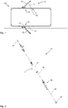
- Figure 1 shows a schematic top view of a motor vehicle 100 stopping at a roadside, in which here two door devices 53 are provided, both of which are open.
- the doors are each approximately in an angular position 13.
- the doors are each part of a door component 50, which here includes the doors 53. It is also possible that a door 53 is attached to the door component 50.
- the door component 50 in any case comprises connection units 51 and 52 for connection to the support structure 101 of the vehicle 100 or to the door 53 in order to pivotally accommodate the door on the support structure 101.
- the door can consist of several pivotable units that are hinged together.
- the door can be pivotally received on one or two or more pivot axes.
- a hatched area 53 shows a door 53 in the closed position 2, in which the door is flush with the vehicle.
- the invention When such a process is detected, the invention immediately sets a maximum damping so that damage can be avoided to a very large extent.
- the method can also be carried out with the door components described below.
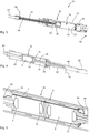
- FIG. 2 an exploded view of the door component 50 is shown in an enlarged representation, the door component 50 comprising a damper device 1 which has a damper on a magnetorheological basis.
- the door component 50 in Figure 2 has connection units 51 and 52 for connection to the supporting structure 101 and the door 53 in order to pivot the door in a defined and controlled manner during the transfer from the Figure 1 shown open position in the also in Figure 1 indicated closed position 2.
- the damper device 1 comprises a cylinder unit 31, in which the piston 38 of the piston unit 30 variably divides the cylinder volume 32 into a first chamber 33 and a second chamber 34.
- An equalizing volume 36 of an equalizing chamber serves to equalize the piston rod 43 immersed in the cylinder unit 31.
- FIG. 12 shows an enlarged cross-sectional view of part of the door component 50 Figure 2 .
- the piston unit 30 with the piston 38 in which the magnet device 9 with the electrical coil 10 is arranged, can be seen on the damper device 1 shown and installed here in section.
- the piston 38 divides the cylinder volume 32 of the cylinder unit 31 into a first chamber 33 and a second chamber 34.
- the damping valve is arranged outside the piston unit 31.
- the magnet device 9 with the electrical coil 10 is arranged on the damping valve.
- the compensation device with the compensation chamber 37 and the compensation volume 36 is shown in the cylinder unit 31.
- the compensation chamber 37 is separated from the second chamber 34 by a separating piston which slides variably within the cylinder unit 31. It is also possible to place the compensation chamber on the other side, in which case a seal must be made with respect to the piston rod passing through and the first chamber 33.
- the compensation chamber 37 is on the low pressure side of the one-way circuit. Valves for filling the first and second chambers 33, 34 and the compensation chamber 37 are provided.
- the compensation chamber 37 is filled with a gaseous medium under a low pressure, so that the immersed volume of the piston rod 43 can be compensated.
- a sensor device 12 is attached to the piston rod 43, with which an absolute position of the damper device 1 can be detected here.
- the position of the two connection units 51 and 52 relative to one another can be determined by querying the sensor device, so that the angular position of the door 53 is also detected directly with the sensor device.
- connection cables for the electrical coil in the piston 38 and the sensor device 12 are here led out through the piston rod 43.
- Figure 4 shows a variant in which a continuous piston rod or 2 piston rods 43, 44 are provided.
- the interior of the cylinder unit 31 is again divided into two chambers 33 and 34 by the piston 38.
- both piston rods 43 and 44 are led outside at the respective ends, so that immersion of the volume of a piston rod need not be compensated for.
- a compensation device 39 is provided here, which is designed, for example, as a hollow rubber ring or the like and in this respect provides a corresponding volume compensation in the event of a volume expansion or a volume decrease due to temperature differences.
- Such a compensation device can be arranged in the chamber 33 or the chamber 34. Compensation devices are possible in the two chambers 33 and 34.
- the piston 38 is also designed as a damping valve 5 and has one or 2 or more flow channels 7 which connect the first chamber 33 to the second chamber 34.
- the chambers 33 and 34 are filled with a magnetorheological fluid 6.
- the damping is achieved here in that a magnetic device 9 or at least one magnetic device 9 is arranged on the damping valve 5, which comprises hard magnetic material and here also an electrical coil.
- a short electrical pulse on the coil 10 triggers a magnetic pulse which leads to permanent magnetization of the magnet device 9, so that the flow resistance through the flow channel 7 then increases in accordance with the strength of the acting magnetic field 8.
- any desired damping of the door movement of the door 53 can thus be set by appropriate remagnetization of the magnet devices 9. It is also possible to use the coil 10 in addition to a permanent magnetic field in order to dynamically model the magnetic field 8 of the magnetic devices 9.
- the damping can be amplified by a rectified magnetic field and the damping can be weakened or even reduced to zero by a correspondingly oppositely oriented magnetic field.
- the connecting cable 42 or the connecting cable 42 are guided through the piston rod 44 to the outside.
- the piston rod 44 is slidably received in a tube 46.
- the connecting cable 41 is led out of the piston rod and led out through a slot 42 in the tube 46.
- FIG. 4 An example of all exemplary embodiments is in Figure 4 a control device 4 is shown, with which the damping valve 5, the damper device 1 and / or the entire door component 50 can be controlled.
- the control device 4 can also be part of the vehicle 100 or another device.
- Figure 5 shows another variant in which 2 magnetic devices 9 or at least 2 electrical coils 10 and 11 are provided.
- the magnetic coils 10 and 11 of the magnet devices 9 are in turn arranged in the piston 38 of the piston unit 30 within the cylinder unit 31.
- the piston separates 2 chambers 33 and 34 of the cylinder volume 32.
- First and second piston rods 43 and 44 can be provided on both sides or only one piston rod is led out on one side. In such a case, an equalizing chamber 37 with an equalizing volume 36 is again required.
- An electrical coil 10, 11 is used here to generate a magnetic pulse and to permanently magnetize the magnet device 9.
- the other electrical Coil 11, 10 can be used to modulate the currently acting magnetic field.
- FIG. 6 shows another schematically illustrated variant of a damper device 1 of a door component 50 with connection units 51 and 52.
- the damper device 1 has a magnetorheological fluid 6 as the working fluid.
- a piston unit 30 with a piston 38 separates a first chamber 33 from the second chamber 34.
- At least one flow channel 7 leads through the piston.
- the one-way valve 15 opens for the flow of the magnetorheological fluid from the second chamber 34 into the first chamber 33. From there the working fluid is passed through the return channel 35 to the here external damping valve 5, to which a magnetic device 9 and an electrical coil 10 are assigned in order to set the desired damping.
- the damping valve 5 is in turn in flow communication with the second chamber 34 via a second one-way valve 16.
- the working fluid 6 flows in the same direction along the arrows shown.
- magnetorheological fluid is supplied to the compensation chamber 37 or magnetorheological fluid is removed from the compensation chamber 37.
- a compensation volume 36 is provided in the compensation chamber 37, which is filled with a gas.
- One or more sensor devices 12 can be provided in order to detect a relative position of the two connection units 51 and 52 with respect to one another in order to derive an angular position of the door 53 therefrom.
- other angle sensors for. B. are provided on the swivel so that an angular position is output directly.
- an electrical coil 10 for generating a magnetic pulse and for permanent magnetization of the Magnet device 9 used.
- the same or a different electrical coil can be used to modulate the currently acting magnetic field.
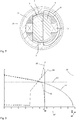
- Figure 7 shows a schematic cross section through the cylinder unit 31 and the piston 38 arranged therein.
- the flow channels 7 of the damping valve 5 are clearly recognizable, which here are each divided into two partial channels by a partition.
- a magnetic field line of the magnetic field 8 is also shown.
- the magnetic field passes approximately perpendicularly through the flow channels 7 of the damping valve.
- the electrical coil 10 serves to generate a variable magnetic field and in particular also to output a magnetic pulse in order to magnetize the magnetic device 9 as desired.
- Figure 8 shows an exemplary diagram of the operation of a door opening process. Normalized variables for speed and deceleration over the angle are shown. The curves of an uncontrolled speed 81 and the associated uncontrolled deceleration 84 are shown, as well as the courses of the controlled speed 82 and the associated controlled deceleration 85 over an opening angle.
- a limit value 80 for a limit acceleration or limit deceleration is also shown.
- the limit value 80 is specified but can be set and changed. If an actual deceleration exceeds the limit value 80, an acute danger situation is recognized and a risk reduction is triggered. This means that the door movement is damped in the following with maximum damping.
- the door is braked with the damper device as soon as possible or immediately after the limit value has been exceeded, and in particular braked as strongly as possible.
- the door is braked because it is assumed that the door has crashed into an obstacle or is still crashing.
- the outer panel of the door initially bends elastically, so that additional braking of the door can possibly completely prevent permanent damage to the door or other objects.
- the door is braked considerably more and in this example comes to a standstill at an angle of just under 46 °.
- the door (without near field detection?) Came to an angle 87 of about 4 ° earlier.
- the angle amount 87 is a direct measure of the absorbed energy and thus also a reduction in the hazard.
- the numerical values given are only to be understood as examples and are only initial values from tests. The exact achievable values depend on many factors.
- the regulation can take place entirely via the position sensor or the angle sensor of the damper device 1. Other values do not have to be included, but can be used.
- the invention can also be used very advantageously. To do this you have to look at the diagram Figure 8 just imagine mirrored horizontally. Meets the door during the closing process e.g. B. on a body part of a user, the delay of the door immediately increases sharply. The door is then damped to a maximum and comes to a standstill much earlier, so that bruising of body parts or damage to objects can be reduced or avoided.
- the door is brought to a standstill with a certain small opening angle during each closing operation, for example at 2.5 ° or at 3 °, in order to avoid fingers being pinched.
- the invention is also used to target the door at certain adjustable or selectable points or positions to bring it to a gentle stop. For this purpose, the door movement is damped accordingly before reaching the desired position.
Landscapes
- Engineering & Computer Science (AREA)
- General Engineering & Computer Science (AREA)
- Mechanical Engineering (AREA)
- Physics & Mathematics (AREA)
- Electromagnetism (AREA)
- Fluid-Damping Devices (AREA)
- Power-Operated Mechanisms For Wings (AREA)
- Vibration Prevention Devices (AREA)
Claims (15)
- Procédé permettant d'amortir un mouvement d'un système de porte (53), notamment d'un véhicule (100) doté d'un système d'amortissement (1) doté d'un amortissement pouvant être réglé et contrôlé, un mouvement d'un système de porte (53) étant amorti de manière contrôlée au moins partiellement entre une position fermée (2) et une position ouverte (3), une mesure d'une vitesse de changement (20) de la vitesse de mouvement (22) du système de porte (53) étant déterminée, caractérisé en ce qu'en cas d'un ralentissement (20) au-delà d'un seuil prédéfini (23), il y a commutation d'un amortissement actuellement réglé à un niveau moins élevé (24) à un amortissement plus élevé (25).
- Procédé selon la revendication précédente, l'amortissement (27) étant réglé à une valeur sensiblement maximale (26) si la vitesse de changement (20) dépasse le seuil prédéfini (23).
- Procédé selon l'une quelconque des deux revendications précédentes, une mesure d'une position et/ou position angulaire (13) du système de porte (53) étant déterminée et l'amortissement (27) étant notamment augmenté si le système de porte (53) se rapproche au moins d'une position angulaire prédéfinie (14) et l'amortissement (27) de préférence étant augmenté si le système de porte (53) se rapproche de la position fermée (2) et l'amortissement (27) notamment étant augmenté de telle sorte que la vitesse de rotation (22) du système de porte (53) est réduite à une vitesse de fermeture prédéfinie (28).
- Procédé selon la revendication précédente, une fonction d'apprentissage étant intégrée, laquelle permet d'analyser des vitesses de fermeture (28) au moment de fermetures, et la vitesse de fermeture prédéfinie (28) étant adaptée de sorte qu'est effectuée une fermeture fiable du système de porte (53) .
- Procédé selon l'une quelconque des deux revendications précédentes, l'amortissement (27) étant augmenté si le système de porte (53) se rapproche d'une position ouverte maximale.
- Procédé notamment selon l'une quelconque des revendications précédentes, l'amortissement (27) n'étant augmenté que si la vitesse de rotation (22) dépasse une vitesse de rotation prédéfinie.
- Procédé notamment selon l'une quelconque des revendications précédentes, l'amortissement (27) étant augmenté si un obstacle (60) est détecté dans la trajectoire de mouvement du système de porte (53) et si une collision est imminente.
- Procédé notamment selon l'une quelconque des revendications précédentes, le système d'amortissement (1) étant contrôlé de telle sorte que la vitesse de rotation (22) du système de porte (53) est telle qu'elle permet d'obtenir une fermeture silencieuse du système de porte (53) et/ou d'obtenir un angle d'ouverture défini sans modification de vitesse soudaine.
- Composante de porte (50) comprenant deux unités de raccordement (51, 52) déplaçables l'une par rapport à l'autre et au moins un système d'amortissement (1) pouvant être contrôlé, l'une des deux unités de raccordement (51, 52) pouvant être connectée à une construction porteuse (101), et l'autre des deux unités de raccordement (51, 52) à un système de porte déplaçable (53), notamment d'un véhicule (100), pour amortir de manière contrôlée par un organe de commande (4) un mouvement du système de porte (53) au moins partiellement entre une position fermée (2) et une position ouverte (3), un système capteur (12) étant associé pour capter une mesure d'une position ou position angulaire (13) du système de porte (53) pivotable, l'organe de commande (4) étant conçu pour et destiné à déterminer, à l'aide de données capteur du système capteur (12), un paramètre d'une vitesse de changement (20) de la vitesse de rotation (22) du système de porte (53), caractérisée en ce qu'en cas d'un ralentissement au-delà d'un seuil limite prédéfini (23), le système d'amortissement (1) est commuté d'un amortissement moins élevé (24) à un amortissement plus élevé (25).
- Composante de porte (50) selon la revendication précédente, le système d'amortissement (1) étant réalisé en tant que système d'amortissement magnéto-rhéologique et l'amortissement étant réglable par le biais d'un champ magnétique (8) modifiable.
- Composante de porte (50) selon l'une quelconque des deux revendications précédentes, la durée nécessaire à la commutation de l'amortissement moins élevé à l'amortissement plus élevé (24, 25) étant inférieure à 50 ms.
- Composante de porte (50) selon l'une quelconque des trois revendications précédentes, l'amortissement (27) étant réglé à une valeur sensiblement maximale (26) si la vitesse de changement (20) dépasse le seuil prédéfini (23).
- Composante de porte selon l'une quelconque des quatre revendications précédentes, l'amortissement (27) étant éteint ou réduit à une valeur moindre si la vitesse ou vitesse de rotation (20) a été réduite à zéro.
- Composante de porte (50) selon l'une quelconque des cinq revendications précédentes, le système d'amortissement (1) comprenant au moins un canal d'écoulement (7) dans lequel peut s'écouler un liquide magnéto-rhéologique (6), ledit canal d'écoulement (7) pouvant être soumis à un champ magnétique (8) modifiable, de sorte que la résistance au flux exercée par le canal d'écoulement (7) et, par conséquent, un amortissement (27) du système d'amortissement (1) pouvant être augmenté par le biais d'un champ magnétique plus fort dans le canal d'écoulement (7) et diminué par le biais d'un champ magnétique plus faible.
- Composante de porte selon l'une quelconque des six revendications précédentes, le système d'amortissement comprenant au moins un système de mesure et une partie du système de mesure étant fixée à la tige de piston.
Applications Claiming Priority (3)
| Application Number | Priority Date | Filing Date | Title |
|---|---|---|---|
| DE102015009449 | 2015-07-21 | ||
| DE102015119505.4A DE102015119505B4 (de) | 2015-07-21 | 2015-11-11 | Türkomponente mit einer steuerbaren Dämpfereinrichtung |
| PCT/EP2016/067473 WO2017013234A1 (fr) | 2015-07-21 | 2016-07-21 | Élément de porte muni d'un dispositif amortisseur pilotable |
Publications (2)
| Publication Number | Publication Date |
|---|---|
| EP3325748A1 EP3325748A1 (fr) | 2018-05-30 |
| EP3325748B1 true EP3325748B1 (fr) | 2020-03-04 |
Family
ID=57738815
Family Applications (5)
| Application Number | Title | Priority Date | Filing Date |
|---|---|---|---|
| EP16751509.7A Active EP3325749B1 (fr) | 2015-07-21 | 2016-07-21 | Élément de porte muni d'un dispositif amortisseur pilotable |
| EP16751507.1A Active EP3325747B1 (fr) | 2015-07-21 | 2016-07-21 | Élément de porte muni d'un dispositif amortisseur pilotable |
| EP16751508.9A Active EP3325748B1 (fr) | 2015-07-21 | 2016-07-21 | Élément de porte muni d'un dispositif amortisseur pilotable |
| EP16751510.5A Active EP3325750B1 (fr) | 2015-07-21 | 2016-07-21 | Élément de porte muni d'un dispositif amortisseur commandable |
| EP16829070.8A Active EP3374587B1 (fr) | 2015-07-21 | 2016-11-11 | Élément de porte avec dispositif d'amortissement commandable |
Family Applications Before (2)
| Application Number | Title | Priority Date | Filing Date |
|---|---|---|---|
| EP16751509.7A Active EP3325749B1 (fr) | 2015-07-21 | 2016-07-21 | Élément de porte muni d'un dispositif amortisseur pilotable |
| EP16751507.1A Active EP3325747B1 (fr) | 2015-07-21 | 2016-07-21 | Élément de porte muni d'un dispositif amortisseur pilotable |
Family Applications After (2)
| Application Number | Title | Priority Date | Filing Date |
|---|---|---|---|
| EP16751510.5A Active EP3325750B1 (fr) | 2015-07-21 | 2016-07-21 | Élément de porte muni d'un dispositif amortisseur commandable |
| EP16829070.8A Active EP3374587B1 (fr) | 2015-07-21 | 2016-11-11 | Élément de porte avec dispositif d'amortissement commandable |
Country Status (6)
| Country | Link |
|---|---|
| US (6) | US10480237B2 (fr) |
| EP (5) | EP3325749B1 (fr) |
| CN (5) | CN108026747B (fr) |
| DE (1) | DE102015119505B4 (fr) |
| MX (2) | MX2018000933A (fr) |
| WO (5) | WO2017013233A1 (fr) |
Families Citing this family (53)
| Publication number | Priority date | Publication date | Assignee | Title |
|---|---|---|---|---|
| DE102015119505B4 (de) * | 2015-07-21 | 2022-12-08 | Inventus Engineering Gmbh | Türkomponente mit einer steuerbaren Dämpfereinrichtung |
| WO2017112729A1 (fr) * | 2015-12-21 | 2017-06-29 | Lord Corporation | Dispositifs, systèmes et procédés d'amortissement de siège perfectionnés |
| DE102016118920B4 (de) | 2016-03-31 | 2019-07-11 | Inventus Engineering Gmbh | Trainingsgerät |
| DE102016221206B4 (de) * | 2016-10-27 | 2018-05-09 | Schaeffler Technologies AG & Co. KG | Elektromechanischer Fahrwerksaktuator |
| DE102016124117B4 (de) * | 2016-12-12 | 2021-05-06 | Inventus Engineering Gmbh | Türkomponente mit einem steuerbaren Drehdämpfer |
| DE102016124114B3 (de) * | 2016-12-12 | 2018-02-15 | Inventus Engineering Gmbh | Türkomponente mit einer steuerbaren Dämpfereinrichtung |
| DE102018103121A1 (de) * | 2018-02-13 | 2019-08-14 | Inventus Engineering Gmbh | Fahrzeugkomponente und Verfahren |
| US20210230921A1 (en) * | 2018-02-13 | 2021-07-29 | Inventus Engineering Gmbh | Vehicle protection system, vehicle component and method |
| US20210179021A1 (en) * | 2018-02-13 | 2021-06-17 | Inventus Engineering Gmbh | Vehicle component and method |
| IT201800004535A1 (it) | 2018-04-16 | 2019-10-16 | Ante incernierate per armadi, cabine armadio e mobili in genere con dispositivi di smorzamento e richiamo magnetici | |
| KR102130510B1 (ko) * | 2018-06-26 | 2020-07-06 | 현대엘리베이터주식회사 | 승강장문 조립체 |
| EP3594437B1 (fr) * | 2018-07-11 | 2022-01-19 | Ningbo Geely Automobile Research & Development Co. Ltd. | Support de positionnement de porte de véhicule |
| DE102018123277A1 (de) * | 2018-09-21 | 2020-03-26 | Kiekert Aktiengesellschaft | Dämpfungseinrichtung und insbesondere Feststeller für eine Tür oder Klappe eines Kraftfahrzeuges |
| CN109083523A (zh) * | 2018-09-25 | 2018-12-25 | 江苏三乔智能科技有限公司 | 门窗支撑杆 |
| DE102018220145A1 (de) * | 2018-11-23 | 2020-05-28 | Brose Fahrzeugteile Se & Co. Kommanditgesellschaft, Bamberg | Verfahren und Verstellvorrichtung zum Verstellen eines Fahrzeugverstellteils mit ausgegebener Statusinformation |
| JP2020111134A (ja) * | 2019-01-10 | 2020-07-27 | アイシン精機株式会社 | 車両用ドア装置 |
| CN111520011A (zh) * | 2019-02-01 | 2020-08-11 | 福州明芳汽车部件工业有限公司 | 用于车门的电动止推系统及其电动止推装置 |
| DE102019121640A1 (de) | 2019-02-11 | 2020-08-13 | Inventus Engineering Gmbh | Türkomponente und Verfahren |
| KR102703741B1 (ko) * | 2019-04-10 | 2024-09-06 | 현대자동차주식회사 | 와셔액 펌프 |
| DE102019110741B4 (de) * | 2019-04-25 | 2023-08-17 | Hochschule Osnabrück | Feststellvorrichtung für ein Türblatt zum Vermitteln einer Information an einen Benutzer beim Öffnen oder Schließen des zu einer Tür gehörenden Türblattes und Türschließer |
| CN110242696B (zh) * | 2019-06-18 | 2020-09-08 | 天津大学 | 一种多级可控变阻尼减振器的变阻尼控制方法 |
| CN110513431B (zh) * | 2019-09-05 | 2020-12-29 | 安徽理工大学 | 一种磁电混合悬浮式液压阻尼器 |
| CN110761624B (zh) * | 2019-09-18 | 2020-12-04 | 珠海格力电器股份有限公司 | 一种锁舌控制方法及门锁系统 |
| IT201900018911A1 (it) * | 2019-10-15 | 2021-04-15 | Caccaro Srl | Ante incernierate per armadi, cabine armadio e mobili in genere con dispositivi di smorzamento e richiamo magnetici |
| JP7397530B2 (ja) * | 2019-10-31 | 2023-12-13 | インベンタス エンジニアリング ゲーエムベーハー | 磁気粘性制動デバイス、特に操作デバイス |
| US20220333423A1 (en) * | 2019-11-01 | 2022-10-20 | Magna Closures Inc. | Powered door unit optimized for servo control |
| CN113062668B (zh) * | 2020-01-02 | 2023-11-28 | 麦格纳覆盖件有限公司 | 用于关闭门的设备和方法 |
| CN111173866B (zh) * | 2020-01-07 | 2021-11-19 | 中车青岛四方车辆研究所有限公司 | 状态检测装置及方法、制动缸、制动夹钳单元及制动系统 |
| CN111271409B (zh) * | 2020-03-26 | 2022-08-05 | 上海大学 | 用于减振并能改变结构刚度的系统 |
| US11725710B2 (en) * | 2020-06-04 | 2023-08-15 | The Boeing Company | Variable fluid damping |
| JP7833787B2 (ja) * | 2020-06-12 | 2026-03-23 | ジャーロフ,ジョセフ,アイヴァン | 足操作式のドアオープナー |
| DE102020124797A1 (de) | 2020-09-23 | 2022-03-24 | Bayerische Motoren Werke Aktiengesellschaft | Verfahren zum Betätigen einer Klappe eines Kraftfahrzeuges |
| DE102020124798A1 (de) | 2020-09-23 | 2022-03-24 | Bayerische Motoren Werke Aktiengesellschaft | Verfahren zum Betätigen einer Klappe eines Kraftfahrzeuges |
| CN112049537B (zh) * | 2020-10-13 | 2024-01-23 | 上海创米数联智能科技发展股份有限公司 | 防撞门的防撞系统、防撞门及防撞方法 |
| CN112360280A (zh) * | 2020-10-23 | 2021-02-12 | 安徽江淮汽车集团股份有限公司 | 汽车关门声品质测试中车门关闭瞬时速度控制系统及方法 |
| DE102020129853A1 (de) * | 2020-11-12 | 2022-05-12 | Otto Bock Healthcare Products Gmbh | Dämpfereinheit und orthopädietechnische Vorrichtung |
| US11781364B2 (en) | 2021-03-30 | 2023-10-10 | AISIN Technical Center of America, Inc. | Automatic control of a power tailgate under external loading |
| US11901725B2 (en) | 2021-03-30 | 2024-02-13 | AISIN Technical Center of America, Inc. | Automatic control of a power tailgate under external loading |
| US12071786B2 (en) * | 2021-04-26 | 2024-08-27 | Westmill Industries Ltd. | Door handle rate controller |
| AT525030A1 (de) | 2021-04-30 | 2022-11-15 | Blum Gmbh Julius | Möbelantriebssystem für ein bewegbares Möbelteil |
| CN115538855B (zh) * | 2021-06-29 | 2024-09-24 | 华为技术有限公司 | 一种门锁控制方法、装置和电子设备 |
| US11199037B1 (en) * | 2021-07-07 | 2021-12-14 | Derek Orion Murr | Limiter for car door closing movement |
| CN113932913B (zh) * | 2021-09-02 | 2024-10-18 | 东风汽车集团股份有限公司 | 一种静音辅助测试装置及关门声品质测试方法 |
| CN113818762A (zh) * | 2021-09-07 | 2021-12-21 | 杨谦 | 一种可在任意位置进行限位的车门限位器 |
| CN114412950B (zh) * | 2021-12-13 | 2024-02-02 | 重庆大学 | 一种多级激励双筒磁流变阻尼器及其控制方法 |
| CN114198451B (zh) * | 2021-12-15 | 2024-03-22 | 中国船舶重工集团公司第七0九研究所 | 一种可控限位的阻尼撑杆的使用方法 |
| CN114439343B (zh) * | 2022-02-24 | 2023-06-27 | 重庆长安汽车股份有限公司 | 一种电动侧开门的电驱动器、安装结构及汽车 |
| CN114714382A (zh) * | 2022-03-07 | 2022-07-08 | 嘉兴学院 | 一种基于磁流变的自适应柔性机械抓手 |
| CN114909039B (zh) * | 2022-04-08 | 2023-01-03 | 邵阳市通达汽车零部件制造有限公司 | 一种无级限位器及其加工设备 |
| CN116181833B (zh) * | 2023-04-24 | 2023-08-29 | 中国科学技术大学 | 乘用车用悬挂设备 |
| DE102023119749A1 (de) * | 2023-06-22 | 2024-12-24 | Inventus Engineering Gmbh | Aktoranordnung mit einer magnetorheologischen Drehbremse |
| CN117345810B (zh) * | 2023-10-27 | 2026-04-10 | 长安大学 | 一种半主动分级耗能变刚度阻尼器 |
| DE102025108838B3 (de) | 2025-03-10 | 2026-04-16 | Audi Aktiengesellschaft | Verschwenken eines bewegbaren Türflügels einer Fahrzeugtür |
Family Cites Families (68)
| Publication number | Priority date | Publication date | Assignee | Title |
|---|---|---|---|---|
| GB1365869A (en) * | 1970-08-15 | 1974-09-04 | Dowty Rotol Ltd | Fluid spring shock absorber |
| US3989286A (en) | 1973-10-11 | 1976-11-02 | Dorma-Baubeschlag Gmbh & Co. Kg | Device for arresting a door |
| JPS60151438A (ja) * | 1984-01-13 | 1985-08-09 | Kayaba Ind Co Ltd | ステアリングダンパ |
| DE3506001A1 (de) | 1985-02-21 | 1986-08-28 | Bayerische Motoren Werke AG, 8000 München | Stossdaempfungseinrichtung |
| JP2581655B2 (ja) * | 1991-03-08 | 1997-02-12 | トックベアリング株式会社 | 高トルク用ダンパ |
| DE4224132C2 (de) * | 1992-07-22 | 2002-11-14 | Stabilus Gmbh | Türfeststellsystem |
| AU671518B2 (en) * | 1993-03-18 | 1996-08-29 | Stabilus Gmbh | A locking device for securing objects which are movable relatively to one another |
| DE19514610A1 (de) | 1994-04-25 | 1995-11-02 | Geze Gmbh & Co | Antrieb zum Öffnen und/oder Schließen eines Flügels, einer Tür, eines Fensters oder dergleichen |
| JPH0814308A (ja) * | 1994-06-27 | 1996-01-16 | Shimadzu Corp | 流体圧シリンダ装置 |
| DE4433056C2 (de) * | 1994-09-16 | 1998-01-29 | Mannesmann Sachs Ag | Schwingungsdämpfer für Kraftfahrzeuge |
| DE4442547C1 (de) * | 1994-11-30 | 1996-06-05 | Daimler Benz Ag | Feststellvorrichtung für eine aufschwenkbare Fahrzeugklappe |
| US6729071B1 (en) * | 1995-10-02 | 2004-05-04 | Ohi Seisakusho Co., Ltd. | Device for automatically controlling opening and closing of a vehicle slide door |
| US7438346B1 (en) * | 1997-03-17 | 2008-10-21 | Automotive Technologies International, Inc. | Method and apparatus for controlling a vehicle door |
| DE19754167B4 (de) | 1997-12-06 | 2008-08-21 | Volkswagen Ag | Vorrichtung zur stufenlosen Arretierung einer um eine Achse schwenkbaren Komponente |
| DE19910782C2 (de) * | 1999-03-11 | 2001-01-25 | Stabilus Gmbh | Türscharnier mit einer Blockierung aufgrund einer Feldkraft |
| FR2790812B1 (fr) | 1999-03-11 | 2001-05-11 | Coutier Moulage Gen Ind | Clapet directionnel a seuil de declenchement et dispositif equipe d'un tel clapet |
| DE19947203A1 (de) * | 1999-10-01 | 2001-04-05 | Audi Ag | Vorrichtung zur Arretierung einer Tür |
| US6382706B2 (en) * | 2000-03-28 | 2002-05-07 | Ohi Seisakusho Co., Ltd. | Operating device for automotive pivotal door |
| US7637360B2 (en) * | 2000-03-29 | 2009-12-29 | Lord Corporation | System comprising magnetically actuated motion control device |
| DE10029227C2 (de) | 2000-06-14 | 2002-04-11 | Daimler Chrysler Ag | Steuerbares Bremssystem |
| US6419057B1 (en) * | 2001-01-12 | 2002-07-16 | Delphi Technologies, Inc. | Power-off damping in MR damper |
| US20020130002A1 (en) * | 2001-03-15 | 2002-09-19 | Delphi Technologies, Inc. | Gas cup seal for magneto-rheological damper |
| GB0113542D0 (en) * | 2001-06-05 | 2001-07-25 | Meritor Light Vehicle Sys Ltd | A mechanism |
| US8225458B1 (en) * | 2001-07-13 | 2012-07-24 | Hoffberg Steven M | Intelligent door restraint |
| CN2525303Y (zh) * | 2002-01-07 | 2002-12-11 | 欧进萍 | 剪切阀式磁流变液减振驱动器 |
| US20030136626A1 (en) * | 2002-01-23 | 2003-07-24 | Ciaramitaro Dina A. | Magneto-rheological clutch assembly for use in an electromechanical system |
| AU2003245136A1 (en) | 2002-06-24 | 2004-01-06 | Intier Automotive Closures Inc. | Door control system for stepless holding of vehicle doors by means of a field force |
| AU2003262787A1 (en) * | 2002-08-21 | 2004-03-11 | Delphi Technologies, Inc. | Controlled truck cab suspension |
| CN2648174Y (zh) * | 2003-09-25 | 2004-10-13 | 欧进萍 | 内藏气囊式双出杆流体阻尼器 |
| US20060181108A1 (en) | 2003-09-29 | 2006-08-17 | Cleland Terry P | Low-mounted powered opening system and control mechanism |
| JP4685380B2 (ja) * | 2004-07-21 | 2011-05-18 | 株式会社ニフコ | 移動体の衝撃吸収装置 |
| WO2005089188A2 (fr) * | 2004-03-12 | 2005-09-29 | General Motors Corporation | Ensembles entretoise a resistance variable et articles contenant ces ensembles |
| CN101818776A (zh) * | 2004-03-25 | 2010-09-01 | 洛德公司 | 包括磁驱动的旋转运动控制装置的系统 |
| DE202004008024U1 (de) * | 2004-05-19 | 2005-10-06 | Bauerfeind Ag | Regelbarer Bewegungsdämpfer |
| KR100569971B1 (ko) | 2004-07-05 | 2006-04-10 | 현대자동차주식회사 | 슬램방지기능을 갖는 자동차의 도어체커 |
| JP2006064102A (ja) * | 2004-08-27 | 2006-03-09 | Kayaba Ind Co Ltd | 両ロッド型ダンパにおける油温補償構造 |
| DE102004061687A1 (de) | 2004-12-22 | 2006-07-06 | Daimlerchrysler Ag | Fahrzeugtür mit einer Abbremsfunktion |
| DE102004061689A1 (de) * | 2004-12-22 | 2006-07-06 | Daimlerchrysler Ag | Fahrzeugtür mit Ausstiegshilfe |
| DE102004061686A1 (de) * | 2004-12-22 | 2006-07-06 | Daimlerchrysler Ag | Fahrzeugtür mit variabler Rastfunktion |
| US20060238285A1 (en) * | 2005-03-30 | 2006-10-26 | Dimig Steven J | Residual magnetic devices and methods |
| DE102006037992A1 (de) | 2006-08-14 | 2008-02-21 | Magna Powertrain Ag & Co Kg | Bauteil mit Haltefunktion, Aufhaltesystem und Verfahren zu deren Betrieb |
| US7761209B2 (en) * | 2007-05-21 | 2010-07-20 | Gm Global Technology Operations, Inc. | Obstruction detection device for vehicle door and method |
| DE102009034297A1 (de) * | 2009-07-21 | 2011-02-03 | Inventus Engineering Gmbh | Einstellbares Ventil mit Übergangsbereich |
| DE102009034298A1 (de) * | 2009-07-21 | 2011-01-27 | Dt Swiss Ag | Dämpfereinrichtung für ein Zweirad |
| DE102009060550B4 (de) * | 2009-12-23 | 2024-06-20 | Dt Swiss Ag | Dämpfereinrichtung für ein Zweirad |
| DE102010019344B3 (de) | 2010-05-05 | 2011-05-19 | Stabilus Gmbh | Antriebseinrichtung |
| FR2960268B1 (fr) * | 2010-05-21 | 2013-04-05 | Sauermann Ind Sa | Pompe electromagnetique a piston oscillant |
| DE102010055828A1 (de) * | 2010-12-23 | 2012-06-28 | Dt Swiss Ag | Fahrwerksteuerung für ein Fahrrad |
| DE102010055830A1 (de) | 2010-12-23 | 2012-06-28 | Dt Swiss Ag | Fahrwerksteuerung für ein Fahrrad |
| US9051989B2 (en) * | 2011-07-12 | 2015-06-09 | Beijingwest Industries Co., Ltd. | Magnetorheological fluid-based mount apparatus including rate dip track passage |
| DE102012016947B4 (de) * | 2012-08-28 | 2023-11-30 | Dt Swiss Ag | Federgabel, insbesondere für Fahrräder |
| DE102012016946A1 (de) | 2012-08-28 | 2014-03-06 | Dt Swiss Ag | Federgabel, insbesondere für Fahrräder |
| DE102012018093A1 (de) * | 2012-09-13 | 2014-03-13 | Kiekert Aktiengesellschaft | Kraftfahrzeugtür sowie Verfahren zur Beaufschlagung einer solchen Kraftfahrzeugtür |
| CN102889332B (zh) | 2012-10-25 | 2015-08-05 | 株洲时代新材料科技股份有限公司 | 一种汽车悬架用磁流变阻尼器 |
| DE102012024376A1 (de) | 2012-12-13 | 2014-06-18 | Kiekert Aktiengesellschaft | Kraftfahrzeugtür |
| DE102013005442B3 (de) * | 2013-03-31 | 2014-08-21 | Inventus Engineering Gmbh | Ventileinrichtung und Verfahren |
| CN103352956B (zh) * | 2013-06-19 | 2015-09-23 | 重庆大学 | 非对称可控阻尼特性的磁流变阻尼器 |
| DE102013014091B4 (de) * | 2013-08-27 | 2023-05-11 | Dt Swiss Ag | Fahrwerksteuerung für ein Zweirad und Verfahren |
| DE102013015595B3 (de) | 2013-09-19 | 2015-03-19 | Gunther Glehr | Vorrichtung zum Begrenzen einer Öffnungsbewegung von zu öffnenden oder schließenden Teilen |
| US9091321B2 (en) * | 2013-09-25 | 2015-07-28 | Honeywell International Inc. | Fluid dampers having temperature-dependent viscosity compensation and auxiliary power unit inlet systems employing the same |
| WO2015048876A1 (fr) * | 2013-10-01 | 2015-04-09 | Warren Industries Ltd. | Système de commande de portière de véhicule |
| DE102013021892A1 (de) * | 2013-12-23 | 2015-06-25 | Dt Swiss Ag | Fahrwerksteuerung für ein Zweirad und Verfahren |
| CN203867356U (zh) | 2014-03-17 | 2014-10-08 | 浙江师范大学 | 一种基于磁流变液的闭门器 |
| CN204249966U (zh) | 2014-09-30 | 2015-04-08 | 浙江吉利控股集团有限公司 | 一种汽车关门声音控制系统 |
| DE102015119505B4 (de) * | 2015-07-21 | 2022-12-08 | Inventus Engineering Gmbh | Türkomponente mit einer steuerbaren Dämpfereinrichtung |
| DE102018103121A1 (de) * | 2018-02-13 | 2019-08-14 | Inventus Engineering Gmbh | Fahrzeugkomponente und Verfahren |
| US20210179021A1 (en) * | 2018-02-13 | 2021-06-17 | Inventus Engineering Gmbh | Vehicle component and method |
| US20210230921A1 (en) * | 2018-02-13 | 2021-07-29 | Inventus Engineering Gmbh | Vehicle protection system, vehicle component and method |
-
2015
- 2015-11-11 DE DE102015119505.4A patent/DE102015119505B4/de active Active
-
2016
- 2016-07-21 MX MX2018000933A patent/MX2018000933A/es unknown
- 2016-07-21 US US15/746,505 patent/US10480237B2/en active Active
- 2016-07-21 EP EP16751509.7A patent/EP3325749B1/fr active Active
- 2016-07-21 CN CN201680054566.XA patent/CN108026747B/zh not_active Expired - Fee Related
- 2016-07-21 EP EP16751507.1A patent/EP3325747B1/fr active Active
- 2016-07-21 CN CN201680054633.8A patent/CN108138531B/zh active Active
- 2016-07-21 US US15/746,503 patent/US10941601B2/en active Active
- 2016-07-21 CN CN201680054348.6A patent/CN108026746B/zh active Active
- 2016-07-21 CN CN201680054683.6A patent/CN108026748B/zh not_active Expired - Fee Related
- 2016-07-21 WO PCT/EP2016/067472 patent/WO2017013233A1/fr not_active Ceased
- 2016-07-21 US US15/746,504 patent/US11236537B2/en not_active Expired - Fee Related
- 2016-07-21 WO PCT/EP2016/067475 patent/WO2017013236A1/fr not_active Ceased
- 2016-07-21 EP EP16751508.9A patent/EP3325748B1/fr active Active
- 2016-07-21 MX MX2018000934A patent/MX2018000934A/es unknown
- 2016-07-21 WO PCT/EP2016/067474 patent/WO2017013235A1/fr not_active Ceased
- 2016-07-21 WO PCT/EP2016/067473 patent/WO2017013234A1/fr not_active Ceased
- 2016-07-21 US US15/746,502 patent/US11391079B2/en active Active
- 2016-07-21 EP EP16751510.5A patent/EP3325750B1/fr active Active
- 2016-11-11 CN CN201680072139.4A patent/CN108368723B/zh active Active
- 2016-11-11 EP EP16829070.8A patent/EP3374587B1/fr active Active
- 2016-11-11 US US15/775,679 patent/US10794103B2/en active Active
- 2016-11-11 WO PCT/EP2016/077474 patent/WO2017081280A2/fr not_active Ceased
-
2022
- 2022-03-30 US US17/708,211 patent/US20220220789A1/en not_active Abandoned
Non-Patent Citations (1)
| Title |
|---|
| None * |
Also Published As
Similar Documents
| Publication | Publication Date | Title |
|---|---|---|
| EP3325748B1 (fr) | Élément de porte muni d'un dispositif amortisseur pilotable | |
| EP1075723B1 (fr) | Dispositif de fermeture avec fonction de securite | |
| EP1982030B1 (fr) | Procédé et dispositif de commande du mouvement de fermeture d'un élément de carrosserie de véhicules automobiles | |
| DE102012011117B4 (de) | Verstellsystem für ein Fahrzeug und Verfahren zum Verstellen eines verstellbaren Elements für ein Fahrzeug | |
| DE10028445B4 (de) | Verfahren zur Steuerung der Verstellbewegung eines mittels eines Elektromotors bewegten Teils einer Schließvorrichtung in einem Fahrzeug | |
| DE102009001668B4 (de) | Betätigungserkennung eines aktiven Arretierungssystems | |
| DE19758796B4 (de) | Verfahren zur Steuerung und Regelung der Verstellbewegung eines translatorisch verstellbaren Bauteils in Fahrzeugen | |
| DE102007062472A1 (de) | Tür, insbesondere Fahrzeugtür, und Verfahren zu deren Betätigung | |
| DE102010023398A1 (de) | Verfahren zum Öffnen und Schließen eines schwenkbeweglichen Karosserieteils eines Kraftfahrzeugs | |
| DE19810077A1 (de) | Auf äußere Krafteinwirkung ansprechendes Fahrzeugtürsteuerungssystem | |
| EP2699748B1 (fr) | Dispositif pour déplacer un élément mobile d'un meuble, et meuble | |
| DE102019210912A1 (de) | Verstellvorrichtung und Verfahren für die fremdkraftbetätigte Verstellung eines Verstellteils an einem Fahrzeug auf Basis wenigstens eines Bedienereignisses | |
| DE102009027597A1 (de) | Verfahren zum Betreiben einer Schließvorrichtung eines Kraftfahrzeugs sowie eine Schließvorrichtung | |
| DE102017220326A1 (de) | Motorantriebsvorrichtung einer Fahrzeugschiebetür | |
| DE102021201049B4 (de) | Verfahren zur motorischen Bewegungsunterstützung oder Bremsung einer Fahrzeugtür | |
| DE102017118894A1 (de) | Verfahren für den Betrieb eines Klappenantriebs | |
| DE102006019581B4 (de) | Kraftfahrzeug mit einer Türvorrichtung zur manuellen und automatischen Türbetätigung | |
| DE102010048758B4 (de) | Verfahren und Vorrichtung zum elektromotorischen Bewegen einer Klappe eines Kraftwagens | |
| DE102015014802A1 (de) | Verfahren und Steuerungseinrichtung zur Steuerung und Überwachung eines Fahrgasttürsystems eines Personen befördernden Fahrzeugs sowie diesbezügliches Fahrzeug | |
| EP3452678A1 (fr) | Dispositif permettant d'agir sur la mobilité d'une porte | |
| EP1746236A2 (fr) | Procédé et dispositif pour détecter un obstacle dans le trajet d'ouverture d'un élément mobile | |
| DE102014205327A1 (de) | Verstellvorrichtung für ein Fahrzeug und Montageverfahren mit Zeitgeber | |
| EP1913222B1 (fr) | Procede de positionnement d'une unite mobile dans un vehicule automobile | |
| DE102015000531B4 (de) | Verfahren zum Betreiben einer Türeinrastvorrichtung und Türeinrastvorrichtung | |
| WO2003048491A1 (fr) | Systeme de deplacement d'un element |
Legal Events
| Date | Code | Title | Description |
|---|---|---|---|
| STAA | Information on the status of an ep patent application or granted ep patent |
Free format text: STATUS: THE INTERNATIONAL PUBLICATION HAS BEEN MADE |
|
| PUAI | Public reference made under article 153(3) epc to a published international application that has entered the european phase |
Free format text: ORIGINAL CODE: 0009012 |
|
| STAA | Information on the status of an ep patent application or granted ep patent |
Free format text: STATUS: REQUEST FOR EXAMINATION WAS MADE |
|
| 17P | Request for examination filed |
Effective date: 20180219 |
|
| AK | Designated contracting states |
Kind code of ref document: A1 Designated state(s): AL AT BE BG CH CY CZ DE DK EE ES FI FR GB GR HR HU IE IS IT LI LT LU LV MC MK MT NL NO PL PT RO RS SE SI SK SM TR |
|
| AX | Request for extension of the european patent |
Extension state: BA ME |
|
| DAV | Request for validation of the european patent (deleted) | ||
| DAX | Request for extension of the european patent (deleted) | ||
| GRAP | Despatch of communication of intention to grant a patent |
Free format text: ORIGINAL CODE: EPIDOSNIGR1 |
|
| STAA | Information on the status of an ep patent application or granted ep patent |
Free format text: STATUS: GRANT OF PATENT IS INTENDED |
|
| INTG | Intention to grant announced |
Effective date: 20190930 |
|
| GRAS | Grant fee paid |
Free format text: ORIGINAL CODE: EPIDOSNIGR3 |
|
| GRAA | (expected) grant |
Free format text: ORIGINAL CODE: 0009210 |
|
| STAA | Information on the status of an ep patent application or granted ep patent |
Free format text: STATUS: THE PATENT HAS BEEN GRANTED |
|
| AK | Designated contracting states |
Kind code of ref document: B1 Designated state(s): AL AT BE BG CH CY CZ DE DK EE ES FI FR GB GR HR HU IE IS IT LI LT LU LV MC MK MT NL NO PL PT RO RS SE SI SK SM TR |
|
| REG | Reference to a national code |
Ref country code: GB Ref legal event code: FG4D Free format text: NOT ENGLISH |
|
| REG | Reference to a national code |
Ref country code: CH Ref legal event code: EP |
|
| REG | Reference to a national code |
Ref country code: AT Ref legal event code: REF Ref document number: 1240539 Country of ref document: AT Kind code of ref document: T Effective date: 20200315 |
|
| REG | Reference to a national code |
Ref country code: DE Ref legal event code: R096 Ref document number: 502016009046 Country of ref document: DE |
|
| REG | Reference to a national code |
Ref country code: IE Ref legal event code: FG4D Free format text: LANGUAGE OF EP DOCUMENT: GERMAN |
|
| PG25 | Lapsed in a contracting state [announced via postgrant information from national office to epo] |
Ref country code: RS Free format text: LAPSE BECAUSE OF FAILURE TO SUBMIT A TRANSLATION OF THE DESCRIPTION OR TO PAY THE FEE WITHIN THE PRESCRIBED TIME-LIMIT Effective date: 20200304 Ref country code: NO Free format text: LAPSE BECAUSE OF FAILURE TO SUBMIT A TRANSLATION OF THE DESCRIPTION OR TO PAY THE FEE WITHIN THE PRESCRIBED TIME-LIMIT Effective date: 20200604 Ref country code: FI Free format text: LAPSE BECAUSE OF FAILURE TO SUBMIT A TRANSLATION OF THE DESCRIPTION OR TO PAY THE FEE WITHIN THE PRESCRIBED TIME-LIMIT Effective date: 20200304 |
|
| REG | Reference to a national code |
Ref country code: NL Ref legal event code: MP Effective date: 20200304 |
|
| PG25 | Lapsed in a contracting state [announced via postgrant information from national office to epo] |
Ref country code: LV Free format text: LAPSE BECAUSE OF FAILURE TO SUBMIT A TRANSLATION OF THE DESCRIPTION OR TO PAY THE FEE WITHIN THE PRESCRIBED TIME-LIMIT Effective date: 20200304 Ref country code: BG Free format text: LAPSE BECAUSE OF FAILURE TO SUBMIT A TRANSLATION OF THE DESCRIPTION OR TO PAY THE FEE WITHIN THE PRESCRIBED TIME-LIMIT Effective date: 20200604 Ref country code: SE Free format text: LAPSE BECAUSE OF FAILURE TO SUBMIT A TRANSLATION OF THE DESCRIPTION OR TO PAY THE FEE WITHIN THE PRESCRIBED TIME-LIMIT Effective date: 20200304 Ref country code: GR Free format text: LAPSE BECAUSE OF FAILURE TO SUBMIT A TRANSLATION OF THE DESCRIPTION OR TO PAY THE FEE WITHIN THE PRESCRIBED TIME-LIMIT Effective date: 20200605 Ref country code: HR Free format text: LAPSE BECAUSE OF FAILURE TO SUBMIT A TRANSLATION OF THE DESCRIPTION OR TO PAY THE FEE WITHIN THE PRESCRIBED TIME-LIMIT Effective date: 20200304 |
|
| REG | Reference to a national code |
Ref country code: LT Ref legal event code: MG4D |
|
| PG25 | Lapsed in a contracting state [announced via postgrant information from national office to epo] |
Ref country code: NL Free format text: LAPSE BECAUSE OF FAILURE TO SUBMIT A TRANSLATION OF THE DESCRIPTION OR TO PAY THE FEE WITHIN THE PRESCRIBED TIME-LIMIT Effective date: 20200304 |
|
| PG25 | Lapsed in a contracting state [announced via postgrant information from national office to epo] |
Ref country code: LT Free format text: LAPSE BECAUSE OF FAILURE TO SUBMIT A TRANSLATION OF THE DESCRIPTION OR TO PAY THE FEE WITHIN THE PRESCRIBED TIME-LIMIT Effective date: 20200304 Ref country code: SK Free format text: LAPSE BECAUSE OF FAILURE TO SUBMIT A TRANSLATION OF THE DESCRIPTION OR TO PAY THE FEE WITHIN THE PRESCRIBED TIME-LIMIT Effective date: 20200304 Ref country code: ES Free format text: LAPSE BECAUSE OF FAILURE TO SUBMIT A TRANSLATION OF THE DESCRIPTION OR TO PAY THE FEE WITHIN THE PRESCRIBED TIME-LIMIT Effective date: 20200304 Ref country code: RO Free format text: LAPSE BECAUSE OF FAILURE TO SUBMIT A TRANSLATION OF THE DESCRIPTION OR TO PAY THE FEE WITHIN THE PRESCRIBED TIME-LIMIT Effective date: 20200304 Ref country code: IS Free format text: LAPSE BECAUSE OF FAILURE TO SUBMIT A TRANSLATION OF THE DESCRIPTION OR TO PAY THE FEE WITHIN THE PRESCRIBED TIME-LIMIT Effective date: 20200704 Ref country code: CZ Free format text: LAPSE BECAUSE OF FAILURE TO SUBMIT A TRANSLATION OF THE DESCRIPTION OR TO PAY THE FEE WITHIN THE PRESCRIBED TIME-LIMIT Effective date: 20200304 Ref country code: EE Free format text: LAPSE BECAUSE OF FAILURE TO SUBMIT A TRANSLATION OF THE DESCRIPTION OR TO PAY THE FEE WITHIN THE PRESCRIBED TIME-LIMIT Effective date: 20200304 Ref country code: PT Free format text: LAPSE BECAUSE OF FAILURE TO SUBMIT A TRANSLATION OF THE DESCRIPTION OR TO PAY THE FEE WITHIN THE PRESCRIBED TIME-LIMIT Effective date: 20200729 Ref country code: SM Free format text: LAPSE BECAUSE OF FAILURE TO SUBMIT A TRANSLATION OF THE DESCRIPTION OR TO PAY THE FEE WITHIN THE PRESCRIBED TIME-LIMIT Effective date: 20200304 |
|
| REG | Reference to a national code |
Ref country code: DE Ref legal event code: R097 Ref document number: 502016009046 Country of ref document: DE |
|
| PLBE | No opposition filed within time limit |
Free format text: ORIGINAL CODE: 0009261 |
|
| STAA | Information on the status of an ep patent application or granted ep patent |
Free format text: STATUS: NO OPPOSITION FILED WITHIN TIME LIMIT |
|
| PG25 | Lapsed in a contracting state [announced via postgrant information from national office to epo] |
Ref country code: DK Free format text: LAPSE BECAUSE OF FAILURE TO SUBMIT A TRANSLATION OF THE DESCRIPTION OR TO PAY THE FEE WITHIN THE PRESCRIBED TIME-LIMIT Effective date: 20200304 Ref country code: IT Free format text: LAPSE BECAUSE OF FAILURE TO SUBMIT A TRANSLATION OF THE DESCRIPTION OR TO PAY THE FEE WITHIN THE PRESCRIBED TIME-LIMIT Effective date: 20200304 |
|
| 26N | No opposition filed |
Effective date: 20201207 |
|
| PG25 | Lapsed in a contracting state [announced via postgrant information from national office to epo] |
Ref country code: SI Free format text: LAPSE BECAUSE OF FAILURE TO SUBMIT A TRANSLATION OF THE DESCRIPTION OR TO PAY THE FEE WITHIN THE PRESCRIBED TIME-LIMIT Effective date: 20200304 Ref country code: PL Free format text: LAPSE BECAUSE OF FAILURE TO SUBMIT A TRANSLATION OF THE DESCRIPTION OR TO PAY THE FEE WITHIN THE PRESCRIBED TIME-LIMIT Effective date: 20200304 Ref country code: MC Free format text: LAPSE BECAUSE OF FAILURE TO SUBMIT A TRANSLATION OF THE DESCRIPTION OR TO PAY THE FEE WITHIN THE PRESCRIBED TIME-LIMIT Effective date: 20200304 |
|
| REG | Reference to a national code |
Ref country code: CH Ref legal event code: PL |
|
| GBPC | Gb: european patent ceased through non-payment of renewal fee |
Effective date: 20200721 |
|
| REG | Reference to a national code |
Ref country code: BE Ref legal event code: MM Effective date: 20200731 |
|
| PG25 | Lapsed in a contracting state [announced via postgrant information from national office to epo] |
Ref country code: GB Free format text: LAPSE BECAUSE OF NON-PAYMENT OF DUE FEES Effective date: 20200721 Ref country code: LI Free format text: LAPSE BECAUSE OF NON-PAYMENT OF DUE FEES Effective date: 20200731 Ref country code: LU Free format text: LAPSE BECAUSE OF NON-PAYMENT OF DUE FEES Effective date: 20200721 Ref country code: CH Free format text: LAPSE BECAUSE OF NON-PAYMENT OF DUE FEES Effective date: 20200731 |
|
| PG25 | Lapsed in a contracting state [announced via postgrant information from national office to epo] |
Ref country code: BE Free format text: LAPSE BECAUSE OF NON-PAYMENT OF DUE FEES Effective date: 20200731 |
|
| PG25 | Lapsed in a contracting state [announced via postgrant information from national office to epo] |
Ref country code: IE Free format text: LAPSE BECAUSE OF NON-PAYMENT OF DUE FEES Effective date: 20200721 |
|
| PG25 | Lapsed in a contracting state [announced via postgrant information from national office to epo] |
Ref country code: TR Free format text: LAPSE BECAUSE OF FAILURE TO SUBMIT A TRANSLATION OF THE DESCRIPTION OR TO PAY THE FEE WITHIN THE PRESCRIBED TIME-LIMIT Effective date: 20200304 Ref country code: MT Free format text: LAPSE BECAUSE OF FAILURE TO SUBMIT A TRANSLATION OF THE DESCRIPTION OR TO PAY THE FEE WITHIN THE PRESCRIBED TIME-LIMIT Effective date: 20200304 Ref country code: CY Free format text: LAPSE BECAUSE OF FAILURE TO SUBMIT A TRANSLATION OF THE DESCRIPTION OR TO PAY THE FEE WITHIN THE PRESCRIBED TIME-LIMIT Effective date: 20200304 |
|
| PG25 | Lapsed in a contracting state [announced via postgrant information from national office to epo] |
Ref country code: MK Free format text: LAPSE BECAUSE OF FAILURE TO SUBMIT A TRANSLATION OF THE DESCRIPTION OR TO PAY THE FEE WITHIN THE PRESCRIBED TIME-LIMIT Effective date: 20200304 Ref country code: AL Free format text: LAPSE BECAUSE OF FAILURE TO SUBMIT A TRANSLATION OF THE DESCRIPTION OR TO PAY THE FEE WITHIN THE PRESCRIBED TIME-LIMIT Effective date: 20200304 |
|
| REG | Reference to a national code |
Ref country code: AT Ref legal event code: MM01 Ref document number: 1240539 Country of ref document: AT Kind code of ref document: T Effective date: 20210721 |
|
| PG25 | Lapsed in a contracting state [announced via postgrant information from national office to epo] |
Ref country code: AT Free format text: LAPSE BECAUSE OF NON-PAYMENT OF DUE FEES Effective date: 20210721 |
|
| P01 | Opt-out of the competence of the unified patent court (upc) registered |
Effective date: 20230525 |
|
| PGFP | Annual fee paid to national office [announced via postgrant information from national office to epo] |
Ref country code: DE Payment date: 20250819 Year of fee payment: 10 |
|
| PGFP | Annual fee paid to national office [announced via postgrant information from national office to epo] |
Ref country code: FR Payment date: 20250723 Year of fee payment: 10 |