EP2995386B1 - Device for securing a glue applicator to a power screwdriver or drill - Google Patents
Device for securing a glue applicator to a power screwdriver or drill Download PDFInfo
- Publication number
- EP2995386B1 EP2995386B1 EP15002671.4A EP15002671A EP2995386B1 EP 2995386 B1 EP2995386 B1 EP 2995386B1 EP 15002671 A EP15002671 A EP 15002671A EP 2995386 B1 EP2995386 B1 EP 2995386B1
- Authority
- EP
- European Patent Office
- Prior art keywords
- screwdriver
- connecting arm
- drill
- forks
- axis
- Prior art date
- Legal status (The legal status is an assumption and is not a legal conclusion. Google has not performed a legal analysis and makes no representation as to the accuracy of the status listed.)
- Active
Links
Images

Classifications
-
- B—PERFORMING OPERATIONS; TRANSPORTING
- B05—SPRAYING OR ATOMISING IN GENERAL; APPLYING FLUENT MATERIALS TO SURFACES, IN GENERAL
- B05C—APPARATUS FOR APPLYING FLUENT MATERIALS TO SURFACES, IN GENERAL
- B05C17/00—Hand tools or apparatus using hand held tools, for applying liquids or other fluent materials to, for spreading applied liquids or other fluent materials on, or for partially removing applied liquids or other fluent materials from, surfaces
- B05C17/005—Hand tools or apparatus using hand held tools, for applying liquids or other fluent materials to, for spreading applied liquids or other fluent materials on, or for partially removing applied liquids or other fluent materials from, surfaces for discharging material from a reservoir or container located in or on the hand tool through an outlet orifice by pressure without using surface contacting members like pads or brushes
- B05C17/01—Hand tools or apparatus using hand held tools, for applying liquids or other fluent materials to, for spreading applied liquids or other fluent materials on, or for partially removing applied liquids or other fluent materials from, surfaces for discharging material from a reservoir or container located in or on the hand tool through an outlet orifice by pressure without using surface contacting members like pads or brushes with manually mechanically or electrically actuated piston or the like
- B05C17/0103—Hand tools or apparatus using hand held tools, for applying liquids or other fluent materials to, for spreading applied liquids or other fluent materials on, or for partially removing applied liquids or other fluent materials from, surfaces for discharging material from a reservoir or container located in or on the hand tool through an outlet orifice by pressure without using surface contacting members like pads or brushes with manually mechanically or electrically actuated piston or the like with electrically actuated piston or the like
-
- B—PERFORMING OPERATIONS; TRANSPORTING
- B25—HAND TOOLS; PORTABLE POWER-DRIVEN TOOLS; MANIPULATORS
- B25F—COMBINATION OR MULTI-PURPOSE TOOLS NOT OTHERWISE PROVIDED FOR; DETAILS OR COMPONENTS OF PORTABLE POWER-DRIVEN TOOLS NOT PARTICULARLY RELATED TO THE OPERATIONS PERFORMED AND NOT OTHERWISE PROVIDED FOR
- B25F3/00—Associations of tools for different working operations with one portable power-drive means; Adapters therefor
Definitions
- the invention relates to a new mechanical device allowing the mounting of an applicator of glue or other materials, to any type of electric or / and pneumatic drill or screwdriver.
- the object of the invention is achieved with this new device for applying a material contained in a removable deformable cartridge or envelope.
- the mechanical device comprises a main body receiving the cartridge or casing and a pusher for exerting an axial force on a movable bottom of the cartridge or of the deformable casing during the application of the material using a drill. or a motorized screwdriver.
- the device according to the invention benefits from a suitable structure allowing it to be easily and quickly adapted to a simple commercial electric or / and pneumatic drill or screwdriver, and thereby to allow effortless application.
- the patent FROM 29510534 describes a device in which the link arm is fixed and inefficient due to its position near the axis of rotation of the drill.
- the new mechanical device comprises a force transmission means connected to the pusher and shaped so as to cause said pusher to move.
- This translational movement is obtained in a conventional and known manner, forming part of the state of the art, by the transformation of a rotary movement, generated by a motorized hand tool, fixed axially to the body of the application device.
- the object of the present invention will hereinafter be referred to simply as the “device”.
- the device is therefore an accessory capable of being mounted or adapted on a commercial tool in common use and commonly called a drill or screwdriver which thereby overcomes the disadvantages described above.
- the device being intended to be adapted to the body of a motorized drill or screwdriver, the device is then mounted in the operating axis of the electric or / and pneumatic drill or screwdriver.
- the device uses as drive means a motorized drill or screwdriver which the professional as any handyman necessarily has. This detail has a direct and significant impact on the cost of manufacturing the device, which will be very reasonable because it does not include a driving part.
- a fork-shaped movable part adaptable to all commercial drills or screwdrivers, slaves the device in position by preventing it from rotating, clockwise and counterclockwise, around the axis of the drill chuck or motorized screwdriver.
- the transmission means of the device is configured to be connected in rotation to the mandrel of the motorized drill or screwdriver and to transmit the rotational movement generated by the electric or / and pneumatic drill or screwdriver, to the device comprising the pusher.
- the pusher is intended to engage in the rear part of a cartridge or to press on a deformable casing and to rest in particular on a movable bottom of the cartridge in order to be able to exert, when using the device, the pressure necessary to exiting the contents of the cartridge or casing through a nozzle disposed at the opposite end of the cartridge or casing from the movable bottom.
- the device characterizing the invention can be produced in different ways and with several materials, this in no way modifying the subject of the invention.
- Various materials can be used such as stamped or stamped metal sheets, aluminum alloys or molded plastics. This latter embodiment, which is able to serve as a shock and torque damping element during operation of the device, will be preferred to others for obvious reasons of cost, manufacture, maintenance and weight. It remains obvious to those skilled in the art that all the constituent parts of the device can be made of synthetic materials and in particular the shaft and its screw thread.
- a screw / nut type assembly is advantageously used to convert the rotary movement of the motorized drill or screwdriver into a translational movement of a shaft.
- the transmission means essentially comprises a gearbox, called a reduction gearbox, rotated by the motorized drill or screwdriver and transmitting the necessary force to the pusher shaft by transforming this rotational movement into a movement of translation.
- the gearbox can be designed in different ways, all of which are known and forming part of the state of the art.
- the very object of the invention does not relate to the means of transmission, it will simply be mentioned and mentioned. We cite here in a nonlimiting manner and by way of example an embodiment of the device according to the invention.
- a device comprises a body 1 for receiving a cartridge C or a deformable envelope ED containing a mastic, an adhesive or any comparable material.
- the device further comprises a transmission means 3 for receiving a rotational movement generated by an electric hand tool such as a motorized drill or screwdriver O, attached to the body 1 of the device by means of the link arm 4 and for transmitting this rotational movement by means of the transmission means 3 to the pusher P via its shaft T.
- an electric hand tool such as a motorized drill or screwdriver O
- the figure 2 represents the device of the invention in the packaging or storage.
- the transmission means 3 and its force input shaft 6 making it possible to be introduced and clamped in the mandrel ML of a motorized drill or screwdriver O, as well as the link arm 4, supporting the two halves - 5 and 5 'forks materializing a trapezoidal TZ shape, retained by an MS hinge in the folded position.
- the figure 4 schematically represents the first movement of engagement and disengagement of the device on a motorized drill or screwdriver O, more precisely of its mandrel ML, on the attachment end 6 of the gearbox 3.
- the motorized drill or screwdriver O is moved in translation along the force input axis 6 of the device in the direction of the gearbox 3.
- the operation and implementation of the device characterizing the invention is carried out according to the following;
- the main body of the device 1 figures: 1a, 4, 5, 6a, is presented in front of the motorized drill or screwdriver O, the attachment end 6 is inserted into the ML chuck of the motorized drill or screwdriver O, figure 4 .
- the user unfolds the link arm 4 supporting the two half-forks 5 and 5 'and articulated on an MS axis supporting a mechanical means for locking in position, figure 7 .
- the link arm 4 and its two half-forks 5 and 5 'then clamp thanks to their trapezoidal shape TZ, the flanks FL and FL' of the battery (body) B positioned under the handle PO of the motorized drill or screwdriver O and / or the PT work handle and adjust to it more effectively, figures 5 and 6a .
- the user positions a cartridge C or deformable envelope ED, figure 1a, of glue or the like, in the recess provided for this purpose in the main body 1.
- This procedure is conventional for many other materials intended for this purpose. to the same task.
- the link arm 4 in its telescopic version, consists of a body 4 'and a second body 4 "sliding linearly one inside the other, allowing the precise adjustment of the length of the link arm 4 to the motorized drill or screwdriver and its battery (body) B or / and its working handle PT.
Landscapes
- Engineering & Computer Science (AREA)
- Mechanical Engineering (AREA)
- Percussive Tools And Related Accessories (AREA)
- Coating Apparatus (AREA)
- Processing Of Stones Or Stones Resemblance Materials (AREA)
Description
L'invention concerne un nouveau dispositif mécanique permettant le montage d'un applicateur de colle ou autres matières, à tout type de perceuse ou visseuse électrique ou/et pneumatique.The invention relates to a new mechanical device allowing the mounting of an applicator of glue or other materials, to any type of electric or / and pneumatic drill or screwdriver.
Il existe déjà dans le commerce de nombreux matériels permettant l'application de colles et autres matières visqueuses. Ces matériels ont le principal désavantage de ne pas disposer d'un système quelconque de gestion de la quantité de matière à idéalement appliquer.There are already many materials on the market for the application of glues and other viscous materials. These materials have the main disadvantage of not having any system for managing the quantity of material to be ideally applied.
La conception d'un nouveau dispositif d'application de colle ou autre se posait donc qui pallierait les désavantages énoncés ci-avant et allierait les avantages d'une structure et d'un usage simples.The design of a new glue or other application device therefore arose which would overcome the disadvantages stated above and would combine the advantages of a simple structure and use.
Le but de l'invention est atteint avec ce nouveau dispositif d'application d'une matière contenue dans une cartouche ou enveloppe déformable amovible.The object of the invention is achieved with this new device for applying a material contained in a removable deformable cartridge or envelope.
Le dispositif mécanique comprend un corps principal recevant la cartouche ou enveloppe et un poussoir permettant d'exercer une force axiale sur un fond mobile de la cartouche ou de l'enveloppe déformable pendant l'application de la matière à l'aide d'une perceuse ou d'une visseuse motorisée.The mechanical device comprises a main body receiving the cartridge or casing and a pusher for exerting an axial force on a movable bottom of the cartridge or of the deformable casing during the application of the material using a drill. or a motorized screwdriver.
Pour se faire, le dispositif selon l'invention bénéficie d'une structure adaptée lui permettant d'être facilement et rapidement adaptable sur une simple perceuse ou visseuse électrique ou/et pneumatique du commerce, et de permettre par là même une application sans effort.To do so, the device according to the invention benefits from a suitable structure allowing it to be easily and quickly adapted to a simple commercial electric or / and pneumatic drill or screwdriver, and thereby to allow effortless application.
Le dispositif selon l'invention comprend :
- i) un corps principal (1) apte à recevoir une enveloppe déformable (ED) ou une cartouche comprenant un fond mobile (C), comprenant une matière visqueuse telle que de la colle ou du mastic, et
- ii) un poussoir (P) permettant d'exercer une force axiale sur le fond mobile de la cartouche ou sur la partie arrière de l'enveloppe déformable pour l'application d'une matière visqueuse,
- iii) un moyen de transmission (3) de force relié au poussoir (P) et conformé afin de faire translater ledit poussoir (P) par la transformation du mouvement rotatif, généré par une perceuse ou une visseuse motorisée (O), en mouvement linéaire, lorsque celle-ci est couplée audit moyen de transmission (3) par un axe d'entrée de force (6) du dispositif, et
- iv) au moins un bras de liaison (4) comportant deux demi-fourches (5, 5') permettant l'asservissement dans le sens horaire et antihoraire du corps principal (1) à une perceuse ou visseuse motorisée (O),
- v) un moyen mécanique de blocage (MS) en position du bras de liaison et des deux demi-fourches (5, 5'),
- vi) au moins un axe d'articulation supportant le moyen mécanique de blocage (MS) en position ;
caractérisé en ce que ledit au moins un axe d'articulation est horizontal et perpendiculaire à l'axe (6).The device according to the invention comprises:
- i) a main body (1) adapted to receive a deformable envelope (ED) or a cartridge comprising a movable bottom (C), comprising a viscous material such as glue or mastic, and
- ii) a pusher (P) making it possible to exert an axial force on the movable bottom of the cartridge or on the rear part of the deformable casing for the application of a viscous material,
- iii) a force transmission means (3) connected to the pusher (P) and shaped in order to cause said pusher (P) to move by transforming the rotary movement, generated by a drill or a motorized screwdriver (O), into linear movement , when the latter is coupled to said transmission means (3) by a force input axis (6) of the device, and
- iv) at least one link arm (4) comprising two half-forks (5, 5 ') allowing clockwise and anti-clockwise slaving of the main body (1) to a motorized drill or screwdriver (O),
- v) a mechanical locking means (MS) in position of the link arm and the two half-forks (5, 5 '),
- vi) at least one hinge pin supporting the mechanical locking means (MS) in position;
characterized in that said at least one articulation axis is horizontal and perpendicular to the axis (6).
Le brevet
La demande internationale
Le brevet
Plus spécifiquement, le nouveau dispositif mécanique selon l'invention comprend un moyen de transmission de force relié au poussoir et conformé afin de faire translater ledit poussoir. Ce mouvement de translation est obtenu de manière classique et connue, faisant partie de l'état de l'art, par la transformation d'un mouvement rotatif, généré par un outil à main motorisé, fixé axialement au corps du dispositif d'application.More specifically, the new mechanical device according to the invention comprises a force transmission means connected to the pusher and shaped so as to cause said pusher to move. This translational movement is obtained in a conventional and known manner, forming part of the state of the art, by the transformation of a rotary movement, generated by a motorized hand tool, fixed axially to the body of the application device.
Pour rendre plus facilement compréhensible la description ci-après de l'invention, l'objet de la présente invention sera appelé par la suite tout simplement le "dispositif".To make the following description of the invention more easily understandable, the object of the present invention will hereinafter be referred to simply as the “device”.
Le dispositif est donc un accessoire capable d'être monté ou adapté sur un outil du commerce d'usage courant et communément appelé perceuse ou visseuse qui pallie de ce fait les désavantages décrits plus avant. En effet, le dispositif étant destiné à être adapté au corps d'une perceuse ou visseuse motorisée, le dispositif se trouve alors monté dans l'axe de fonctionnement de la perceuse ou visseuse électrique ou/et pneumatique. Le dispositif utilise comme moyen d'entraînement une perceuse ou visseuse motorisée dont le professionnel comme tout bricoleur dispose nécessairement. Ce détail a un impact direct et notable sur le coût de fabrication du dispositif qui sera très raisonnable du fait que celui-ci ne comporte pas de partie motrice.The device is therefore an accessory capable of being mounted or adapted on a commercial tool in common use and commonly called a drill or screwdriver which thereby overcomes the disadvantages described above. Indeed, the device being intended to be adapted to the body of a motorized drill or screwdriver, the device is then mounted in the operating axis of the electric or / and pneumatic drill or screwdriver. The device uses as drive means a motorized drill or screwdriver which the professional as any handyman necessarily has. This detail has a direct and significant impact on the cost of manufacturing the device, which will be very reasonable because it does not include a driving part.
La disposition axiale du corps du dispositif avec une perceuse ou visseuse motorisée, sur laquelle le dispositif est monté en « bout ». Une pièce mobile, en forme de fourche, adaptable à toutes les perceuses ou visseuses du commerce, asservit en position le dispositif en lui interdisant un mouvement de rotation, dans le sens horaire et antihoraire, autour de l'axe du mandrin de la perceuse ou visseuse motorisée.The axial arrangement of the body of the device with a motorized drill or screwdriver, on which the device is mounted “end”. A fork-shaped movable part, adaptable to all commercial drills or screwdrivers, slaves the device in position by preventing it from rotating, clockwise and counterclockwise, around the axis of the drill chuck or motorized screwdriver.
Le moyen de transmission du dispositif est conformé pour être relié en rotation au mandrin de la perceuse ou visseuse motorisée et transmettre le mouvement en rotation généré par la perceuse ou la visseuse électrique ou/et pneumatique, au dispositif comprenant le poussoir. Le poussoir est destiné à s'engager dans la partie arrière d'une cartouche ou appuyer sur une enveloppe déformable et prendre appui notamment sur un fond mobile de la cartouche afin de pouvoir exercer, lors de l'utilisation du dispositif, la pression nécessaire pour faire sortir le contenu de la cartouche ou de l'enveloppe par une buse disposée à l'extrémité opposée de la cartouche ou de l'enveloppe par rapport au fond mobile.The transmission means of the device is configured to be connected in rotation to the mandrel of the motorized drill or screwdriver and to transmit the rotational movement generated by the electric or / and pneumatic drill or screwdriver, to the device comprising the pusher. The pusher is intended to engage in the rear part of a cartridge or to press on a deformable casing and to rest in particular on a movable bottom of the cartridge in order to be able to exert, when using the device, the pressure necessary to exiting the contents of the cartridge or casing through a nozzle disposed at the opposite end of the cartridge or casing from the movable bottom.
Le dispositif caractérisant l'invention peut être réalisé de différentes façons et avec plusieurs matières, ceci ne modifiant en rien l'objet de l'invention. Différents matériaux sont utilisables tels que des feuilles de métal estampées ou embouties des alliages d'aluminium ou des matières synthétiques moulées. Ce dernier moyen de réalisation qui est apte à servir d'élément amortisseur de choc et de couple pendant le fonctionnement du dispositif sera préféré à d'autres pour d'évidents intérêts de coût, de fabrication, d'entretien et de poids. Il reste évident, à l'homme de l'art, que toutes les pièces constitutives du dispositif peuvent être réalisées en matières synthétiques et notamment l'arbre et son pas de vis.The device characterizing the invention can be produced in different ways and with several materials, this in no way modifying the subject of the invention. Various materials can be used such as stamped or stamped metal sheets, aluminum alloys or molded plastics. This latter embodiment, which is able to serve as a shock and torque damping element during operation of the device, will be preferred to others for obvious reasons of cost, manufacture, maintenance and weight. It remains obvious to those skilled in the art that all the constituent parts of the device can be made of synthetic materials and in particular the shaft and its screw thread.
Afin d'obtenir une force idéalement exploitable à l'aide du moyen de transmission du dispositif, un ensemble de type vis/écrou est avantageusement utilisé pour convertir le mouvement rotatif de la perceuse ou visseuse motorisée en un mouvement de translation d'un arbre.In order to obtain an ideally exploitable force with the aid of the transmission means of the device, a screw / nut type assembly is advantageously used to convert the rotary movement of the motorized drill or screwdriver into a translational movement of a shaft.
A cet effet, le moyen de transmission comporte essentiellement une boîte d'engrenage, dite de démultiplication, mise en rotation par la perceuse ou visseuse motorisée et transmettant la force nécessaire à l'arbre du poussoir en transformant ce mouvement de rotation en un mouvement de translation.To this end, the transmission means essentially comprises a gearbox, called a reduction gearbox, rotated by the motorized drill or screwdriver and transmitting the necessary force to the pusher shaft by transforming this rotational movement into a movement of translation.
La boîte de démultiplication peut être conçue de différentes façons, toutes connues et faisant partie de l'état de l'art. L'objet même de l'invention ne concernant pas le moyen de transmission, celui-ci sera simplement évoqué et mentionné. Nous citons ici de manière non limitative et à titre d'exemple un mode de réalisation du dispositif selon l'invention.The gearbox can be designed in different ways, all of which are known and forming part of the state of the art. The very object of the invention does not relate to the means of transmission, it will simply be mentioned and mentioned. We cite here in a nonlimiting manner and by way of example an embodiment of the device according to the invention.
Le dispositif selon l'invention peut, par ailleurs, comprendre également l'une au moins des caractéristiques ci-après, considérées isolément ou selon toute combinaison techniquement possible :
- le dispositif comprend un bras mécanique, télescopique ou non, pour solidariser et asservir le dispositif à une perceuse ou visseuse motorisée, et lui interdire un mouvement de rotation horaire et antihoraire. De par la distance entre l'axe de rotation et point de liaison de la perceuse ou visseuse électrique et du corps du dispositif à l'extrémité des deux demi-fourches est possiblement le plus éloigné. Cette distance, facilement réglable grâce aux avantages de l'invention, fait que le mouvement de rotation horaire et antihoraire est notamment avantageusement interdit par la longueur du bras de liaison générant un important effet de levier représentant un moment mécanique idéal favorable à la diminution des contraintes sur le bras lui-même et la perceuse ou visseuse motorisée.
- le bras mécanique de liaison du corps du dispositif à la perceuse ou visseuse motorisée s'articule sur un ou plusieurs axes, mais préférablement un et leurs moyens mécaniques de blocage en position. Ces moyens de blocage peuvent être obtenus par une simple combinaison « vis écrou » ou être composés d'un levier avec came pour assurer la même fonction et plus généralement tout mécanisme permettant d'assujettir le bras de liaison au corps de l'outil à main en position.
- the device comprises a mechanical arm, telescopic or not, for securing and slaving the device to a motorized drill or screwdriver, and to prevent it from rotating clockwise and counterclockwise. From the distance between the axis of rotation and the connection point of the electric drill or screwdriver and the body of the device at the end of the two half-forks is possibly the furthest. This distance, easily adjustable thanks to the advantages of the invention, means that the clockwise and anti-clockwise rotation movement is in particular advantageously prohibited by the length of the link arm generating a significant leverage effect representing a moment. ideal mechanics favorable to the reduction of stresses on the arm itself and the motorized drill or screwdriver.
- the mechanical arm connecting the body of the device to the motorized drill or screwdriver is articulated on one or more axes, but preferably one and their mechanical means for locking in position. These locking means can be obtained by a simple combination of "screw and nut" or be composed of a lever with cam to ensure the same function and more generally any mechanism making it possible to secure the link arm to the body of the hand tool. in position.
D'autres caractéristiques et avantages de la présente invention ressortiront de la description détaillée de ce mode de réalisation, description faite en référence aux dessins dans lesquels :
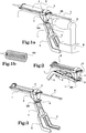
- la figure la représente, en une vue en perspective, un ensemble formé par le dispositif selon l'invention, muni d'une cartouche ou d'une enveloppe déformable et une perceuse ou visseuse motorisée solidarisée au dispositif par son bras de liaison.
- la
figure 1b montre un exemple d'enveloppe déformable pouvant être utilisées pas le dispositif selon l'invention. - la
figure 2 représente, en une vue en perspective, le dispositif seul, avec son bras de liaison en position repliée, tel qu'il doit l'être pour son conditionnement ou son rangement. Son poussoir et son arbre sont montrés en position extrême avant. - la
figure 3 représente le dispositif avec son bras de liaison en position dépliée et le poussoir en position extrême arrière, l'arbre, solidaire du poussoir est en position sortie. - la
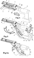
figure 4 représente schématiquement l'engagement et le désengagement du dispositif dans la perceuse ou visseuse motorisée, la flèche « F1 » montre explicitement le premier mouvement d'assemblage du dispositif sur la perceuse ou visseuse motorisée, par l'intermédiaire de l'axe d'entrée de force et le mandrin de ladite perceuse ou visseuse motorisée. - la
figure 5 représente aussi schématiquement l'assujettissement du dispositif au corps de la perceuse ou visseuse motorisée par l'intermédiaire de son bras de liaison. La flèche « F2 » montre explicitement le second mouvement d'asservissement du dispositif sur la perceuse ou visseuse motorisée. La flèche SR matérialise l'arrêt en rotation horaire et antihoraire de la perceuse ou visseuse motorisée autour de l'axe ML. La distance D montre le point d'appui des fourches du bras sur les flancs FL et FL' de la batterie B positionnée sous la poignée PO de la perceuse ou visseuse motorisée. - la
figure 6a montre le dispositif en position de travail, sur la perceuse ou visseuse motorisée, avec son bras de liaison à une articulation, entre le dispositif et la perceuse ou visseuse motorisée, avec la possibilité d'ajuster au mieux ledit bras de liaison au corps et/ou une poignée de travail susceptible d'être montée sur une quelconque perceuse ou visseuse motorisée. L'angle « α » pouvant être modifié à volonté selon le type de perceuse ou visseuse motorisée. - la
figure 6b montre la forme particulière matérialisée par les deux demi-fourches du bras de liaison en forme de trapèze. Cette forme, qui caractérise aussi avantageusement le dispositif selon l'invention, facilite l'assujettissement du bras de liaison à tout type de perceuse ou visseuse motorisée connu dans le commerce.
- FIG. la shows, in a perspective view, an assembly formed by the device according to the invention, provided with a cartridge or a deformable casing and a motorized drill or screwdriver secured to the device by its link arm.
- the
figure 1b shows an example of a deformable envelope that can be used by the device according to the invention. - the
figure 2 shows, in a perspective view, the device alone, with its link arm in the folded position, as it should be for its packaging or storage. Its pusher and shaft are shown in the extreme forward position. - the
figure 3 shows the device with its link arm in the unfolded position and the pusher in the extreme rear position, the shaft, integral with the pusher, is in the extended position. - the
figure 4 schematically represents the engagement and disengagement of the device in the motorized drill or screwdriver, the arrow “F1” explicitly shows the first assembly movement of the device on the motorized drill or screwdriver, via the force input axis and the mandrel of said motorized drill or screwdriver. - the
figure 5 also schematically shows the subjection of the device to the body of the motorized drill or screwdriver by means of its link arm. The arrow “F2” explicitly shows the second servo movement of the device on the motorized drill or screwdriver. The SR arrow represents the stop in clockwise and counterclockwise rotation of the motorized drill or screwdriver around the ML axis. The distance D shows the fulcrum of the forks of the arm on the sides FL and FL 'of battery B positioned under the handle PO of the motorized drill or screwdriver. - the
figure 6a shows the device in working position, on the motorized drill or screwdriver, with its linkage arm to an articulation, between the device and the motorized drill or screwdriver, with the possibility of best adjusting said linkage arm to the body and / or a work handle capable of being mounted on any motorized drill or screwdriver. The angle “α” can be modified at will according to the type of motorized drill or screwdriver. - the
figure 6b shows the particular shape materialized by the two half-forks of the trapezoidal link arm. This shape, which also advantageously characterizes the device according to the invention, facilitates the subjection of the link arm to any type of motorized drill or screwdriver known in the trade.
Selon un mode de réalisation particulier, le bras de liaison (4) est muni de deux demi-fourches (5 et 5') permettant l'asservissement dans le sens horaire et antihoraire du corps principal (1) à celui de la perceuse ou visseuse motorisée (O) ; lesquelles deux demi-fourches (5 et 5') forment un trapèze (TZ) facilitant l'assujettissement du bras de liaison (4) à tout type de perceuse ou visseuse motorisée (O).
- la
figure 7 montre un moyen de blocage à l'aide d'une combinaison vis/écrou, du bras de liaison en position de travail. - la
figure 8a représente le bras de liaison, dans sa version télescopique, en position dépliée. La flèche « F3 » montre explicitement le second mouvement de coulissement linéaire du corps du dispositif autour du bras de liaison. Un moyen de blocage, MSB, permet le maintien en position dépliée du corps coulissant. - la
figure 8b représente le bras de liaison, dans sa version télescopique, en position repliée. La flèche « F3 » montre explicitement le second mouvement de coulissement linéaire du corps du dispositif autour du bras de liaison. Un moyen de blocage, MSB, permet le maintien en position repliée du corps coulissant.
- the
figure 7 shows a locking means using a screw / nut combination, of the link arm in the working position. - the
figure 8a shows the link arm, in its telescopic version, in the unfolded position. The arrow “F3” explicitly shows the second linear sliding movement of the body of the device around the link arm. A locking means, MSB, allows the sliding body to be held in the unfolded position. - the
figure 8b shows the link arm, in its telescopic version, in the folded position. The arrow “F3” explicitly shows the second linear sliding movement of the body of the device around the link arm. A locking means, MSB, allows the sliding body to be held in the folded position.
Comme cela est représenté sur la
La
La
Au contraire, lors du désengagement de la perceuse ou visseuse motorisée O de l'embout de fixation 6, la perceuse ou visseuse motorisée O est poussée en éloignement de la boîte de démultiplication 3.On the contrary, when the motorized drill or screwdriver O is disengaged from the
Le fonctionnement et la mise en œuvre du dispositif caractérisant l'invention s'effectue selon ce qui suit ;
Le corps principal du dispositif 1 figures : la, 4, 5, 6a, est présenté devant la perceuse ou visseuse motorisée O, l'embout de fixation 6 est inséré dans le mandrin ML de la perceuse ou visseuse motorisée O,
The main body of the
Dans un autre mode de réalisation, le bras de liaison 4, dans sa version télescopique, est constitué d'un corps 4' et d'un second corps 4" coulissant linéairement l'un dans l'autre, permettant le réglage précis de la longueur du bras de liaison 4 à la perceuse ou visseuse motorisée et sa batterie (corps) B ou/ et sa poignée de travail PT.In another embodiment, the
Claims (7)
- A device comprising:i) a main body (1) adapted to receive a deformable envelope (ED) or a cartridge comprising a movable bottom (C), comprising a viscous material such as glue or masticii) a plunger (P) for exerting an axial force on a movable cartridge bottom or on a deformable envelope rear part for the application of a viscous material,iii) force transmission means (3) connected to the plunger (P) and conformed so as to translate said plunger (P) by the transformation of the rotary motion, generated by a power drill or screwdriver (O), into linear motion, when the latter is coupled to said transmission means (3) by a force input axis (6) of the device, andiv) at least one connecting arm (4) including two half-forks (5, 5') for controlling the main body (1) clockwise and counterclockwise with a power drill or screwdriver (O),v) mechanical means (MS) for locking in position the connecting arm and the two half-forks (5, 5'),vi) at least one hinge axis supporting the mechanical position locking means (MS);which connecting arm (4) is hinged about said at least one hinge axis and the position locking mechanical means,
characterized in that said at least one hinge axis is horizontal and perpendicular to the axis (6). - The device according to claim 1, characterized by the fact that the two half-forks (5, 5') of the connecting arm (4) have support points, capable of stopping the main body (1) rotating clockwise and counterclockwise with respect to a power drill or screwdriver (O).
- The device according to claims 1 or 2, characterized in that said two half-forks (5 and 5') form a trapezium (TZ) facilitating any type of power drill or screwdriver (O) controlling the connecting arm (4).
- The device according to claim 3, characterized in that the hinge about the hinge axis is capable of allowing the deployment and adjustment of the connecting arm (4) at an angle (α), measured in a vertical plane passing through the axis (6).
- The device according to claim 5, characterized in that the connecting arm (4) is foldable under the body (1) and held in position by the locking means (MS), in order to facilitate its packaging and storage.
- The device according to any one of the preceding claims, characterized in that the connecting arm (4), and possibly its two half-forks (5 and 5'), are made of molded synthetic material and suitable for serving as a shock and torque damping element during the operation of the device.
- The device according to any one of the preceding claims, characterized in that the connecting arm (4) comprises a first body (4') sliding linearly relative to a second body (4") so as to form a telescopic connecting arm (4).
Applications Claiming Priority (1)
| Application Number | Priority Date | Filing Date | Title |
|---|---|---|---|
| FR1402043A FR3025730B1 (en) | 2014-09-15 | 2014-09-15 | NEW DEVICE FOR SOLIDARIZING A GLUE APPLICATOR, OR OTHER PRODUCT, ON A DRILL OR SCREWDRIVER |
Publications (2)
| Publication Number | Publication Date |
|---|---|
| EP2995386A1 EP2995386A1 (en) | 2016-03-16 |
| EP2995386B1 true EP2995386B1 (en) | 2020-08-05 |
Family
ID=52589418
Family Applications (1)
| Application Number | Title | Priority Date | Filing Date |
|---|---|---|---|
| EP15002671.4A Active EP2995386B1 (en) | 2014-09-15 | 2015-09-15 | Device for securing a glue applicator to a power screwdriver or drill |
Country Status (2)
| Country | Link |
|---|---|
| EP (1) | EP2995386B1 (en) |
| FR (1) | FR3025730B1 (en) |
Cited By (2)
| Publication number | Priority date | Publication date | Assignee | Title |
|---|---|---|---|---|
| US20220331942A1 (en) * | 2021-04-16 | 2022-10-20 | Black & Decker Inc. | Power tool accessory system with brace |
| US20240066676A1 (en) * | 2021-04-16 | 2024-02-29 | Black & Decker Inc. | Power tool accessory system with brace |
Families Citing this family (4)
| Publication number | Priority date | Publication date | Assignee | Title |
|---|---|---|---|---|
| DE102020205316A1 (en) | 2020-04-27 | 2021-10-28 | Festool Gmbh | Attachment and procedure |
| USD951741S1 (en) | 2020-10-14 | 2022-05-17 | Simpson Strong-Tie Company Inc. | Screw driving tool |
| USD951050S1 (en) | 2020-10-14 | 2022-05-10 | Simpson Strong-Tie Company Inc. | Fastener driving tool adapter |
| CN114043524B (en) * | 2021-12-10 | 2023-12-26 | 上海锐数微医疗科技发展有限公司 | Foldable mechanical arm capable of being locked |
Family Cites Families (7)
| Publication number | Priority date | Publication date | Assignee | Title |
|---|---|---|---|---|
| US3913799A (en) * | 1974-02-28 | 1975-10-21 | Davis George B Jun | Caulking gun adapter for electric hand drill |
| US5058781A (en) * | 1990-10-29 | 1991-10-22 | Aronie Alan B | Caulking gun with drive means which facilitate the immediate release of pressure from the piston |
| FR2732625A1 (en) * | 1995-04-10 | 1996-10-11 | Fechino Mireille Latapy | Dispenser for viscous, paste or liquid product contained in cartridge |
| DE29510534U1 (en) * | 1995-06-29 | 1996-10-31 | Fischerwerke Artur Fischer Gmbh & Co Kg, 72178 Waldachtal | Squeezing device for cartridges |
| US6041976A (en) * | 1998-05-14 | 2000-03-28 | Robertson; Roger C. | Adhesive dispensing tool for use with a rotary power tool |
| FR2929537B1 (en) * | 2008-04-07 | 2011-03-18 | Fabien Viennois | GUN FOR APPLYING MATERIAL CONTAINED IN A CARTRIDGE. |
| WO2010122558A1 (en) * | 2009-04-22 | 2010-10-28 | Wadeeh Zahr | Material dispensing system |
-
2014
- 2014-09-15 FR FR1402043A patent/FR3025730B1/en not_active Expired - Fee Related
-
2015
- 2015-09-15 EP EP15002671.4A patent/EP2995386B1/en active Active
Non-Patent Citations (1)
| Title |
|---|
| None * |
Cited By (2)
| Publication number | Priority date | Publication date | Assignee | Title |
|---|---|---|---|---|
| US20220331942A1 (en) * | 2021-04-16 | 2022-10-20 | Black & Decker Inc. | Power tool accessory system with brace |
| US20240066676A1 (en) * | 2021-04-16 | 2024-02-29 | Black & Decker Inc. | Power tool accessory system with brace |
Also Published As
| Publication number | Publication date |
|---|---|
| FR3025730B1 (en) | 2018-03-09 |
| EP2995386A1 (en) | 2016-03-16 |
| FR3025730A1 (en) | 2016-03-18 |
Similar Documents
| Publication | Publication Date | Title |
|---|---|---|
| EP2995386B1 (en) | Device for securing a glue applicator to a power screwdriver or drill | |
| EP1961531B1 (en) | Tightening device with a retractable manoeuvring arm and apparatus including such a device | |
| EP2389264B1 (en) | Tool holder mandrel for equipping a rotating machine | |
| EP0623429A1 (en) | Pneumatic tool | |
| FR3000418A3 (en) | MECHANISM FOR ATTACHING ACCESSORIES AND ELECTRIC TOOL EQUIPPED | |
| CH707490A1 (en) | torque wrench. | |
| EP1702694B1 (en) | Tool chuck for rotating machine, provided with locking means | |
| CA2591973A1 (en) | Ratchet wrench | |
| FR2678538A1 (en) | Screwing tool | |
| EP1883486B1 (en) | Tool-holder chuck for equipping a rotating machine, in particular of the impact wrench type | |
| EP1649980B1 (en) | Torque limiting tool | |
| EP1345001B1 (en) | Rifle with detachable barrel mounting | |
| EP3416880A1 (en) | Adjustable compression suspension kit for a vehicle | |
| FR2929537A1 (en) | Material e.g. silicone mastic, spray gun for e.g. electrical screw gun, has transmission unit and adjustable length elastic thong that are rotated by hand tool for communicating translation movement to pusher | |
| FR2766117A1 (en) | Spanner for threaded fasteners | |
| EP3829014B1 (en) | Appliance with tilting appliance mounting and a locking system releasable by means of a tilting activation key | |
| EP0468859B1 (en) | Screwing tool with predeterminable torque | |
| EP1992535B1 (en) | Device for controlling an automobile parking brake | |
| FR3022816A1 (en) | TOOL FOR ESTABLISHING A TIGHTENING FIXATION IN A DIFFICULT AREA OF ACCESS | |
| FR2924969A1 (en) | Clamp piece for fixing anchoring plug to hollow material, has reception box moving aside head of screw from bush, where sliding of box is caused by push of handle towards front and towards another handle to move aside case's support surface | |
| EP1764467A2 (en) | Box exit, especially for the support of a drive crank of a roller shutter and drive device with such a box exit | |
| FR2907868A1 (en) | Dry monodisk type friction clutch for motor vehicle, has cover including end part that is extended in axial direction of clutch and is adjusted on axial peripheral surface of fly-wheel by radial fixation screw of radial axis | |
| FR2746743A1 (en) | Vehicle windscreen wiper arm | |
| FR3052089A1 (en) | CHUCK HOLDER | |
| EP1504848A1 (en) | Vice-grip pliers |
Legal Events
| Date | Code | Title | Description |
|---|---|---|---|
| PUAI | Public reference made under article 153(3) epc to a published international application that has entered the european phase |
Free format text: ORIGINAL CODE: 0009012 |
|
| AK | Designated contracting states |
Kind code of ref document: A1 Designated state(s): AL AT BE BG CH CY CZ DE DK EE ES FI FR GB GR HR HU IE IS IT LI LT LU LV MC MK MT NL NO PL PT RO RS SE SI SK SM TR |
|
| AX | Request for extension of the european patent |
Extension state: BA ME |
|
| 17P | Request for examination filed |
Effective date: 20160719 |
|
| RBV | Designated contracting states (corrected) |
Designated state(s): AL AT BE BG CH CY CZ DE DK EE ES FI FR GB GR HR HU IE IS IT LI LT LU LV MC MK MT NL NO PL PT RO RS SE SI SK SM TR |
|
| STAA | Information on the status of an ep patent application or granted ep patent |
Free format text: STATUS: EXAMINATION IS IN PROGRESS |
|
| 17Q | First examination report despatched |
Effective date: 20190322 |
|
| RAP1 | Party data changed (applicant data changed or rights of an application transferred) |
Owner name: ALPHA INDUSTRIE PLASTIQUE |
|
| RIN1 | Information on inventor provided before grant (corrected) |
Inventor name: VIENNOIS, FABIEN |
|
| GRAP | Despatch of communication of intention to grant a patent |
Free format text: ORIGINAL CODE: EPIDOSNIGR1 |
|
| STAA | Information on the status of an ep patent application or granted ep patent |
Free format text: STATUS: GRANT OF PATENT IS INTENDED |
|
| RIC1 | Information provided on ipc code assigned before grant |
Ipc: B05C 17/01 20060101AFI20200127BHEP Ipc: B25F 3/00 20060101ALI20200127BHEP |
|
| INTG | Intention to grant announced |
Effective date: 20200227 |
|
| GRAS | Grant fee paid |
Free format text: ORIGINAL CODE: EPIDOSNIGR3 |
|
| GRAA | (expected) grant |
Free format text: ORIGINAL CODE: 0009210 |
|
| STAA | Information on the status of an ep patent application or granted ep patent |
Free format text: STATUS: THE PATENT HAS BEEN GRANTED |
|
| AK | Designated contracting states |
Kind code of ref document: B1 Designated state(s): AL AT BE BG CH CY CZ DE DK EE ES FI FR GB GR HR HU IE IS IT LI LT LU LV MC MK MT NL NO PL PT RO RS SE SI SK SM TR |
|
| REG | Reference to a national code |
Ref country code: GB Ref legal event code: FG4D Free format text: NOT ENGLISH |
|
| REG | Reference to a national code |
Ref country code: CH Ref legal event code: EP |
|
| REG | Reference to a national code |
Ref country code: AT Ref legal event code: REF Ref document number: 1297976 Country of ref document: AT Kind code of ref document: T Effective date: 20200815 |
|
| REG | Reference to a national code |
Ref country code: DE Ref legal event code: R096 Ref document number: 602015056769 Country of ref document: DE |
|
| REG | Reference to a national code |
Ref country code: IE Ref legal event code: FG4D Free format text: LANGUAGE OF EP DOCUMENT: FRENCH |
|
| REG | Reference to a national code |
Ref country code: CH Ref legal event code: NV Representative=s name: VALIPAT S.A. C/O BOVARD SA NEUCHATEL, CH |
|
| REG | Reference to a national code |
Ref country code: LT Ref legal event code: MG4D |
|
| REG | Reference to a national code |
Ref country code: NL Ref legal event code: MP Effective date: 20200805 |
|
| REG | Reference to a national code |
Ref country code: AT Ref legal event code: MK05 Ref document number: 1297976 Country of ref document: AT Kind code of ref document: T Effective date: 20200805 |
|
| PG25 | Lapsed in a contracting state [announced via postgrant information from national office to epo] |
Ref country code: PT Free format text: LAPSE BECAUSE OF FAILURE TO SUBMIT A TRANSLATION OF THE DESCRIPTION OR TO PAY THE FEE WITHIN THE PRESCRIBED TIME-LIMIT Effective date: 20201207 Ref country code: BG Free format text: LAPSE BECAUSE OF FAILURE TO SUBMIT A TRANSLATION OF THE DESCRIPTION OR TO PAY THE FEE WITHIN THE PRESCRIBED TIME-LIMIT Effective date: 20201105 Ref country code: ES Free format text: LAPSE BECAUSE OF FAILURE TO SUBMIT A TRANSLATION OF THE DESCRIPTION OR TO PAY THE FEE WITHIN THE PRESCRIBED TIME-LIMIT Effective date: 20200805 Ref country code: LT Free format text: LAPSE BECAUSE OF FAILURE TO SUBMIT A TRANSLATION OF THE DESCRIPTION OR TO PAY THE FEE WITHIN THE PRESCRIBED TIME-LIMIT Effective date: 20200805 Ref country code: HR Free format text: LAPSE BECAUSE OF FAILURE TO SUBMIT A TRANSLATION OF THE DESCRIPTION OR TO PAY THE FEE WITHIN THE PRESCRIBED TIME-LIMIT Effective date: 20200805 Ref country code: AT Free format text: LAPSE BECAUSE OF FAILURE TO SUBMIT A TRANSLATION OF THE DESCRIPTION OR TO PAY THE FEE WITHIN THE PRESCRIBED TIME-LIMIT Effective date: 20200805 Ref country code: SE Free format text: LAPSE BECAUSE OF FAILURE TO SUBMIT A TRANSLATION OF THE DESCRIPTION OR TO PAY THE FEE WITHIN THE PRESCRIBED TIME-LIMIT Effective date: 20200805 Ref country code: NO Free format text: LAPSE BECAUSE OF FAILURE TO SUBMIT A TRANSLATION OF THE DESCRIPTION OR TO PAY THE FEE WITHIN THE PRESCRIBED TIME-LIMIT Effective date: 20201105 Ref country code: FI Free format text: LAPSE BECAUSE OF FAILURE TO SUBMIT A TRANSLATION OF THE DESCRIPTION OR TO PAY THE FEE WITHIN THE PRESCRIBED TIME-LIMIT Effective date: 20200805 Ref country code: GR Free format text: LAPSE BECAUSE OF FAILURE TO SUBMIT A TRANSLATION OF THE DESCRIPTION OR TO PAY THE FEE WITHIN THE PRESCRIBED TIME-LIMIT Effective date: 20201106 |
|
| PG25 | Lapsed in a contracting state [announced via postgrant information from national office to epo] |
Ref country code: RS Free format text: LAPSE BECAUSE OF FAILURE TO SUBMIT A TRANSLATION OF THE DESCRIPTION OR TO PAY THE FEE WITHIN THE PRESCRIBED TIME-LIMIT Effective date: 20200805 Ref country code: NL Free format text: LAPSE BECAUSE OF FAILURE TO SUBMIT A TRANSLATION OF THE DESCRIPTION OR TO PAY THE FEE WITHIN THE PRESCRIBED TIME-LIMIT Effective date: 20200805 Ref country code: LV Free format text: LAPSE BECAUSE OF FAILURE TO SUBMIT A TRANSLATION OF THE DESCRIPTION OR TO PAY THE FEE WITHIN THE PRESCRIBED TIME-LIMIT Effective date: 20200805 Ref country code: PL Free format text: LAPSE BECAUSE OF FAILURE TO SUBMIT A TRANSLATION OF THE DESCRIPTION OR TO PAY THE FEE WITHIN THE PRESCRIBED TIME-LIMIT Effective date: 20200805 Ref country code: IS Free format text: LAPSE BECAUSE OF FAILURE TO SUBMIT A TRANSLATION OF THE DESCRIPTION OR TO PAY THE FEE WITHIN THE PRESCRIBED TIME-LIMIT Effective date: 20201205 |
|
| PG25 | Lapsed in a contracting state [announced via postgrant information from national office to epo] |
Ref country code: EE Free format text: LAPSE BECAUSE OF FAILURE TO SUBMIT A TRANSLATION OF THE DESCRIPTION OR TO PAY THE FEE WITHIN THE PRESCRIBED TIME-LIMIT Effective date: 20200805 Ref country code: SM Free format text: LAPSE BECAUSE OF FAILURE TO SUBMIT A TRANSLATION OF THE DESCRIPTION OR TO PAY THE FEE WITHIN THE PRESCRIBED TIME-LIMIT Effective date: 20200805 Ref country code: RO Free format text: LAPSE BECAUSE OF FAILURE TO SUBMIT A TRANSLATION OF THE DESCRIPTION OR TO PAY THE FEE WITHIN THE PRESCRIBED TIME-LIMIT Effective date: 20200805 Ref country code: DK Free format text: LAPSE BECAUSE OF FAILURE TO SUBMIT A TRANSLATION OF THE DESCRIPTION OR TO PAY THE FEE WITHIN THE PRESCRIBED TIME-LIMIT Effective date: 20200805 Ref country code: CZ Free format text: LAPSE BECAUSE OF FAILURE TO SUBMIT A TRANSLATION OF THE DESCRIPTION OR TO PAY THE FEE WITHIN THE PRESCRIBED TIME-LIMIT Effective date: 20200805 |
|
| REG | Reference to a national code |
Ref country code: DE Ref legal event code: R097 Ref document number: 602015056769 Country of ref document: DE |
|
| PG25 | Lapsed in a contracting state [announced via postgrant information from national office to epo] |
Ref country code: AL Free format text: LAPSE BECAUSE OF FAILURE TO SUBMIT A TRANSLATION OF THE DESCRIPTION OR TO PAY THE FEE WITHIN THE PRESCRIBED TIME-LIMIT Effective date: 20200805 Ref country code: MC Free format text: LAPSE BECAUSE OF FAILURE TO SUBMIT A TRANSLATION OF THE DESCRIPTION OR TO PAY THE FEE WITHIN THE PRESCRIBED TIME-LIMIT Effective date: 20200805 |
|
| PLBE | No opposition filed within time limit |
Free format text: ORIGINAL CODE: 0009261 |
|
| STAA | Information on the status of an ep patent application or granted ep patent |
Free format text: STATUS: NO OPPOSITION FILED WITHIN TIME LIMIT |
|
| PG25 | Lapsed in a contracting state [announced via postgrant information from national office to epo] |
Ref country code: LU Free format text: LAPSE BECAUSE OF NON-PAYMENT OF DUE FEES Effective date: 20200915 Ref country code: SK Free format text: LAPSE BECAUSE OF FAILURE TO SUBMIT A TRANSLATION OF THE DESCRIPTION OR TO PAY THE FEE WITHIN THE PRESCRIBED TIME-LIMIT Effective date: 20200805 |
|
| 26N | No opposition filed |
Effective date: 20210507 |
|
| PG25 | Lapsed in a contracting state [announced via postgrant information from national office to epo] |
Ref country code: IT Free format text: LAPSE BECAUSE OF FAILURE TO SUBMIT A TRANSLATION OF THE DESCRIPTION OR TO PAY THE FEE WITHIN THE PRESCRIBED TIME-LIMIT Effective date: 20200805 |
|
| PG25 | Lapsed in a contracting state [announced via postgrant information from national office to epo] |
Ref country code: SI Free format text: LAPSE BECAUSE OF FAILURE TO SUBMIT A TRANSLATION OF THE DESCRIPTION OR TO PAY THE FEE WITHIN THE PRESCRIBED TIME-LIMIT Effective date: 20200805 Ref country code: IE Free format text: LAPSE BECAUSE OF NON-PAYMENT OF DUE FEES Effective date: 20200915 |
|
| PG25 | Lapsed in a contracting state [announced via postgrant information from national office to epo] |
Ref country code: TR Free format text: LAPSE BECAUSE OF FAILURE TO SUBMIT A TRANSLATION OF THE DESCRIPTION OR TO PAY THE FEE WITHIN THE PRESCRIBED TIME-LIMIT Effective date: 20200805 Ref country code: MT Free format text: LAPSE BECAUSE OF FAILURE TO SUBMIT A TRANSLATION OF THE DESCRIPTION OR TO PAY THE FEE WITHIN THE PRESCRIBED TIME-LIMIT Effective date: 20200805 Ref country code: CY Free format text: LAPSE BECAUSE OF FAILURE TO SUBMIT A TRANSLATION OF THE DESCRIPTION OR TO PAY THE FEE WITHIN THE PRESCRIBED TIME-LIMIT Effective date: 20200805 |
|
| PG25 | Lapsed in a contracting state [announced via postgrant information from national office to epo] |
Ref country code: MK Free format text: LAPSE BECAUSE OF FAILURE TO SUBMIT A TRANSLATION OF THE DESCRIPTION OR TO PAY THE FEE WITHIN THE PRESCRIBED TIME-LIMIT Effective date: 20200805 |
|
| PGFP | Annual fee paid to national office [announced via postgrant information from national office to epo] |
Ref country code: DE Payment date: 20240925 Year of fee payment: 10 |
|
| PGFP | Annual fee paid to national office [announced via postgrant information from national office to epo] |
Ref country code: GB Payment date: 20240919 Year of fee payment: 10 |
|
| PGFP | Annual fee paid to national office [announced via postgrant information from national office to epo] |
Ref country code: BE Payment date: 20240926 Year of fee payment: 10 |
|
| PGFP | Annual fee paid to national office [announced via postgrant information from national office to epo] |
Ref country code: CH Payment date: 20241001 Year of fee payment: 10 |
|
| PGFP | Annual fee paid to national office [announced via postgrant information from national office to epo] |
Ref country code: FR Payment date: 20250919 Year of fee payment: 11 |