EP2995475B1 - Système de surveillance pneumatique de pneu - Google Patents
Système de surveillance pneumatique de pneu Download PDFInfo
- Publication number
- EP2995475B1 EP2995475B1 EP14184075.1A EP14184075A EP2995475B1 EP 2995475 B1 EP2995475 B1 EP 2995475B1 EP 14184075 A EP14184075 A EP 14184075A EP 2995475 B1 EP2995475 B1 EP 2995475B1
- Authority
- EP
- European Patent Office
- Prior art keywords
- tire
- processing unit
- data processing
- tire pressure
- mode
- Prior art date
- Legal status (The legal status is an assumption and is not a legal conclusion. Google has not performed a legal analysis and makes no representation as to the accuracy of the status listed.)
- Not-in-force
Links
Images





Classifications
-
- B—PERFORMING OPERATIONS; TRANSPORTING
- B60—VEHICLES IN GENERAL
- B60C—VEHICLE TYRES; TYRE INFLATION; TYRE CHANGING; CONNECTING VALVES TO INFLATABLE ELASTIC BODIES IN GENERAL; DEVICES OR ARRANGEMENTS RELATED TO TYRES
- B60C23/00—Devices for measuring, signalling, controlling, or distributing tyre pressure or temperature, specially adapted for mounting on vehicles; Arrangement of tyre inflating devices on vehicles, e.g. of pumps or of tanks; Tyre cooling arrangements
- B60C23/02—Signalling devices actuated by tyre pressure
- B60C23/04—Signalling devices actuated by tyre pressure mounted on the wheel or tyre
- B60C23/0408—Signalling devices actuated by tyre pressure mounted on the wheel or tyre transmitting the signals by non-mechanical means from the wheel or tyre to a vehicle body mounted receiver
- B60C23/0471—System initialisation, e.g. upload or calibration of operating parameters
-
- B—PERFORMING OPERATIONS; TRANSPORTING
- B60—VEHICLES IN GENERAL
- B60C—VEHICLE TYRES; TYRE INFLATION; TYRE CHANGING; CONNECTING VALVES TO INFLATABLE ELASTIC BODIES IN GENERAL; DEVICES OR ARRANGEMENTS RELATED TO TYRES
- B60C23/00—Devices for measuring, signalling, controlling, or distributing tyre pressure or temperature, specially adapted for mounting on vehicles; Arrangement of tyre inflating devices on vehicles, e.g. of pumps or of tanks; Tyre cooling arrangements
- B60C23/02—Signalling devices actuated by tyre pressure
- B60C23/04—Signalling devices actuated by tyre pressure mounted on the wheel or tyre
- B60C23/0401—Signalling devices actuated by tyre pressure mounted on the wheel or tyre characterised by the type of alarm
Definitions
- the present invention relates to a tire pressure monitoring system, and particularly to a tire pressure monitoring system that allows a driver to quickly learn a tire condition of any tire of a vehicle according to requirements of the driver.
- a conventional tire pressure monitory auxiliary system usually includes a plurality of tire pressure sensing modules.
- the tire pressure sensing modules sense respective tire conditions of a vehicle, and immediately remind a user through a beeper or an alarm light when the tire conditions of the vehicle are sensed abnormal.
- a conventional tire pressure monitoring system is incapable of quickly feeding a user with tire condition information of any tire.
- WO 2011 033015 A relates to a tyre inflation control system according to the preamble of claim 1 for a tractor which has an inflation means for inflating and deflating tyres of the tractor.
- Conduits connect the inflation means with the tyres, and a control means connected with the inflation means is provided for storing predetermined tyre pressure levels and initiating the changing of the inflation pressure of the tyres between the predetermined pressure levels set in the control means.
- the predetermined tyre pressure levels can conveniently correspond to a field work pressure level and a road work pressure level and the control means can store inflation pressures for the tyres of both the tractor and any associated trailer or machine being towed by the tractor.
- the control means may include an electronic display monitor with a touch sensitive screen through which the predetermined levels of tyre pressure can be entered. The sensor selection is done by activating a touch pad position. The rotation knob is used to change the desired pressure values.
- US 2002 130 771 A relates to a system for remotely sensing the temperature and pressure in vehicle tires whether moving or stationary.
- the tire pressure and temperature data along with a unique ID number are transmitted from a sensor in the tire to a computer display in the cab.
- a portable cab display receives the data and assigns a unique wheel location for each sensor.
- the cab display compensates the pressure data for local barometric pressure and actual tire temperature and displays the compensated data to the driver. Alarms are included to alert the driver of off specification conditions.
- the cab display may be removed from the cab for local use.
- the sensor selection is performed by activating push buttons.
- a primary object of the present invention is to allow a driver to quickly learn a tire condition of any tire of a vehicle.
- a secondary object of the present invention is provide tire pressure simulation graphic data that simulates a tire pressure change of one of the tires of a vehicle within a monitoring period, so as to allow a driver to quickly learn a time point liable to an abnormality in the tire pressure according to the tire pressure simulation graphic data.
- the tire pressure monitoring system includes a plurality of tire pressure sensing modules and an information display module.
- the tire pressure sensing modules are respectively installed on tires of a vehicle and each has a device identification code.
- Each of the tire pressure modules includes a detection unit and a first data transmission unit.
- the detection unit constantly detects a tire condition of the tire and outputs tire condition information.
- the first data transmission unit in information connection with the detection unit, transmits the tire condition information and the device identification code.
- the information display module in information connection with the tire pressure sensing modules, includes a second data transmission unit, a data processing unit, a display unit, and a stepless knob.
- the second data transmission unit is connected to the first data transmission units to receive the device identification codes and the tire condition information of the tire pressure sensing modules.
- the data processing unit obtains the device identification codes and the tire condition information from the second data transmission unit, and associates each of the device identification codes with a device selection code.
- the display unit in information connection with the data processing unit, displays the tire condition information obtained from the data processing unit.
- the stepless knob in information connection with the data processing unit, outputs at least one selection signal to the data processing unit by a control means.
- the selection signal is associated with the device selection code.
- the information display module further includes a data storage unit.
- the data storage unit in information connection with the data processing unit, stores the device identification codes and the tire condition information.
- the information display module further includes a setting member.
- the setting member connected to the data processing unit, is configured to enter a task mode preset in the data processing unit when triggered by a user.
- the task mode is an abnormality warning mode.
- the data processing unit has an abnormal condition preset in the data processing unit, and compares the tire condition information with the abnormal condition, and outputs a warning signal to the display unit for display when the tire condition information satisfies the abnormal condition.
- the task mode is an abnormal condition setting mode.
- the data processing unit receives the selection signal outputted from the stepless knob to determine the abnormal condition as a comparison reference value for comparing with the tire condition information.
- the task mode is a data graphicalization mode.
- the data processing mode processes one set of the tire condition information corresponding to one of the device identification codes within a monitoring period to convert the tire condition information to tire pressure simulation graphic data that is displayed at the display unit.
- the task mode is a tire condition polling mode.
- the data processing unit sequentially reads the tire condition information respectively corresponding to the device selection codes at a time interval, and outputs the tire condition information to the display unit for display.
- the task mode is a tire pressure sensing module matching mode.
- the data processing unit prompts the second data transmission unit to search any device identification code detectable within a connection distance, and determines whether the detected device identification code has been previously obtained. If not, the tire pressure sensing module corresponding to the detected device identification code is connected according to the detected device identification code and the current selection signal generated by the stepless knob.
- the present invention has following features compared to a conventional solution.
- a stepless knob is provided by the present invention.
- the stepless knob can be operated by a control means to generate at least selection signal.
- the data processing unit receives the selection signal, analyzes the corresponding device identification code, and reads the tire condition information generated by the corresponding tire pressure sensing module to display the tire condition information at the display unit.
- a driver is allowed to quickly learn the condition of any tire of the vehicle according to requirements.
- a data graphicalization mode is preset in the information display module.
- a tire pressure change of a selected tire within a monitoring period may be presented at the display unit to allow a driver to observe a time point liable to an abnormality in the tire pressure during a driving process.
- a tire pressure monitoring system 1 is provided by the present invention.
- the tire pressure monitoring system 1 is formed by a plurality of tire pressure sensing modules 2 and an information display module 3. More specifically, each of the tire pressure sensing modules 2 is correspondingly installed on one of the tires of a vehicle, and the number of the tire pressure sensing modules 2 can be modified according to the number of the tires of the vehicle.
- an example of a large vehicle having 16 tires is given, and the tire pressure sensing modules 2 are respectively installed on each of the 16 tires.
- each tire pressure sensing module 2 has a device identification code D1.
- the tire pressure sensing module 2 may be implemented in two forms an internal tire pressure sensor and an external tire pressure sensor.
- each tire pressure sensor 2 includes a detection unit 21 and a first data transmission unit 22.
- the detection unit 21 constantly detects an in-tire condition of the corresponding tire assembled, and outputs a set of tire condition information D2.
- the tire condition information D2 may be an internal tire pressure or an internal tire temperature. Further, instead of detecting the internal tire condition only for a traveling vehicle, the detection unit 21 of the present invention may also detect the internal tire condition when the vehicle is at standstill.
- the first data transmission unit 22 constantly receives the tire condition information D2 from the detection unit 21 and sends the same to the information display module 3. Further, in addition to the tire condition information D2, the first data transmission unit 22 of the present invention also at the same time transmits the device identification code D1 representing the corresponding tire pressure sensing module 2.
- the information display module 3 is in information connection with every of the tire pressure sensing modules 2, and includes a second data transmission unit 31, a data processing unit 32, a display unit 33, and a stepless knob 34.
- the second data transmission unit 31 is in information connection with the first data transmission units 22 of the tire pressure sensing modules 2, and receives the tire condition D2 outputted from the first data transmission units 22.
- Data transmission between the second data transmission unit 31 and the first data transmission units 22 may be performed through wired or wireless transmission, e.g., wireless transmission based on the Bluetooth communication protocol.
- the data processing unit 32 is electrically connected to the second data transmission unit 31, and obtains the device identification codes D1 and the tire condition information D2 outputted by the first data transmission units 22 from the second data transmission unit 31. Further, the data processing unit 32 may respectively associate a plurality of preset device selection codes in the data processing unit 32 with the device identification codes D1. In continuation of the above example, as 16 tire pressure sensing modules 2 are installed at the vehicle, the second data transmission unit 31 receives 16 device identification codes D1 in different values. The data processing unit 32 respectively associates the device identification codes D1 with the preset device selection codes. That is to say, each of the device selection codes corresponds to only one of the device identification codes D1.
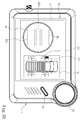
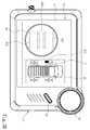
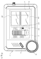
- the display unit 33 is electrically connected to the data processing unit 32, and receives and displays the tire condition information D2 from the data processing unit 32. In one embodiment of the present invention, when powered, the display unit 33 further displays a graphics interface 4.
- the graphics interface 4 includes a tire position display block 41 and a tire information display block 42.
- the tire position display block 41 displays a vehicle image and a plurality of tire images, which represent a current corresponding configuration of the vehicle. Positions where the tire images are configured respectively represent actual positions of the tires of the vehicle, and each tire image corresponds to one of the device selection codes. Further, displayed images in the tire position display block 41 can be displayed by an image that is adjustable according to the different vehicles, and may emphasize a corresponding tire image according to a user selection.
- the tire information display block 42 includes a tire pressure display field 421, a tire temperature display field 422, and a warning signal display field 423.
- the tire pressure display field 421 displays internal tire pressure values included in the tire condition information D2.
- the tire temperature display field 422 displays internal tire pressure values included in the tire condition information D2.
- the warning signal display field 423 warns a driver that the tire condition information D2 received by the information display module 3 exceeds a comparison reference value preset in the data processing unit 32.
- the stepless knob 34 is electrically connected to the data processing unit 32, and is operable by a user by a control means to generate at least one selection signal.
- the control means differs according to implementation methods of the stepless knob 34. For example, when the stepless knob 34 is operated by turning, the control means is a motion that turns the stepless knob 34.
- the stepless knob 34 After generating the selection signal, the stepless knob 34 outputs the selection signal to the data processing unit32 to enable the data processing unit 32 to identify the device selection code represented by the selection signal.
- electrical characteristics of one selection signal generated by the stepless knob 34 of the present invention may be designed to be different from those of another. For example, the selection signals may be distinguished according to differences in voltage values.
- the selection signal may further include a rotary encoder (not shown).
- the rotary encoder determines and converts a rotation amount generated from an operation or a rotated position after the operation to the selection signal.
- the rotary encoder may have four contact points each having a conducted state and a cut-off state, and is rotatable for 360 degrees. According to positions of the four contact points and the rotatable angles of the rotary encoder, the rotary encoder defines a plurality of working intervals. Pin statuses of the working intervals are different to accordingly generate the selection signals having a plurality of different electrical characteristics.
- the data processing unit 32 further includes a data storage unit 35 connected to the data processing unit 32.
- the data storage unit 35 may be a flash memory or an electrically erasable programmable read-only memory (EEPROM), and is for the data processing unit 32 to write data therein or read data therefrom.
- the information display module 3 of the present invention may further include a third data transmission unit 36, which is electrically connected to the data processing unit 32 to be in information connection with an external device. By electrically connecting the third data transmission unit 36 to the data processing unit 32 via an electrical wire, the third data transmission unit 36 allows a driver to update firmware in or access data from the data processing unit 32.
- the third data transmission unit 36 is a Universal Serial Bus (USB) or a Universal Asynchronous Receiver/Transmitter (UART).
- a driver has already selected the information display module 3 to display a tire condition corresponding to an outer front left tire of a vehicle.
- the tire position display block 41 in the graphics interface 4 generated by the powered display unit 33 displays in emphasis the tire image corresponding to the outer front left tire, as shown by 411 in Fig. 3A .
- the tire pressure display field 421 and the tire temperature display field 422 in the tire information display block 42 respectively show the internal tire pressure value and the internal tire temperature value of the outer front left tire.
- the stepless knob 34 may be operated to have the stepless knob 34 generate the selection signal.
- the data processing unit 32 then receives the selection signal, and analyzes the selection signal to identify the corresponding device selection code.
- the data processing unit 32 reads the corresponding device identification code D1 and tire condition information D2 according to the device selection code, and adjusts the tire image displayed in emphasis in the tire position display block 41 according to the device selection code, as shown by 412 in Fig. 3B .
- the data processing unit 32 reads the tire condition information D2 corresponding to the other outer front left tire according to the device selection code and outputs the tire condition information D2 to the display unit 33 for display.
- the tire pressure display field 421 and the tire temperature display field 422 display the internal tire pressure value and the internal tire temperature value corresponding to the other outer front left tire, respectively.
- the information display module 3 further includes a setting member 37 electrically connected to the data processing unit 32.
- the setting member 37 may be implemented in various forms, e.g., a button or a micro switch.
- the data processing unit 32 is prompted to enter a task mode preset in the data processing unit 32.
- the task mode varies according to different application requirements.
- the task mode may be an abnormality warning mode, in which the data processing unit 32 has an abnormal condition preset in the data processing unit 32.
- the abnormal condition may be a comparison reference value, which may represent a threshold that the tire condition approaches to be abnormal or the tire condition is within a normal range.
- the data processing unit 32 constantly compares every set of tire condition information D2 received, and outputs a warning signal to the display unit 33 once the set of tire condition information D2 received satisfies the comparison reference value that serves a limitation in the abnormal condition.
- the display unit 33 displays the warning signal in the warning signal display field 423, which may inform in emphasis the driver about the abnormality of the vehicle tire.
- the data processing unit 32 instead of comparing the tire condition information D2 of one of the tires that is currently displayed, the data processing unit 32 at the same time compares the tire condition information D2 of all the tires of the vehicle. Once the tire condition information D2 of one of the tires satisfies the abnormal condition, the data processing unit 32 outputs the device selection code and the tire condition information D2 corresponding to the abnormality to the display unit 33 to issue a warning.
- the preset task mode in the data processing unit 32 may be an abnormal condition setting mode.
- the data processing unit 32 receives the selection signal outputted by the stepless knob 34, and determines the comparison reference value as the abnormal condition for comparing the tire condition information D2 according to the selection signal. Further, the driver may select to enter the abnormal condition setting mode through the setting member 37 and operate the stepless knob 34 to generate the selection signal.
- the data processing unit 32 correspondingly determines the selection signal as adjusting amplitude of the comparison reference value. For example, the comparison reference value is increased when the stepless knob 34 is turned towards a first direction and decreased when the stepless knob 34 is turned towards a second direction.
- the preset task mode in the data processing unit 32 may be a data graphicalization mode.
- the data processing unit 32 processes one set of the tire condition information D2 corresponding to one of the device identification codes D1 within a monitoring period, and converts the tire condition information D2 to a set of tire pressure simulation graphic data. More specifically, in the embodiment, the driver may select to enter the data graphicalization mode by triggering the setting member 37.
- the driver may set length of the monitoring period and the tire to be monitored, and generate the device selection code of the tire to be monitored through the stepless knob 34 to access the tire condition information D2 to the device selection code.
- the tire pressure simulation graphic data is completed and outputted to the display unit 33, and displayed in the tire information display block 42 of the graphics interface 4.
- the tire condition information D2 may include the internal tire pressure or the internal tire temperature.
- the tire information display block 42 in the data graphicalization mode includes a tire pressure graphics display field 424 and a tire temperature graphics display field 425.
- the tire pressure simulation graphic data of the present invention is not limited to a curve diagram shown in Fig. 5 .
- the data processing unit 32 further includes flag data in the tire pressure simulation graphic data.
- the flag data may be controlled by the selection signal outputted by the stepless knob 34. More specifically, a position of the flag data marked in the tire pressure simulation graphic data is changed by an operation of the driver.
- the flag data indicates a time point of the tire pressure simulation graphic data, and the driver may change the time point that the flag data indicates in the tire pressure simulation graphic data through operating the stepless knob 34.
- the data processing unit 32 further compares the abnormal condition with each set of the tire condition information D2 during the conversion process of the tire pressure simulation graphic data.
- the set of tire condition information D2 satisfying the abnormal condition is indicated in emphasis in the tire pressure simulation graphic data.
- the preset task mode in the data processing unit 32 is a tire condition polling mode.
- the data processing unit 32 sequentially reads the device selection codes at a time interval, and outputs the tire condition information D2 corresponding to the device selection codes to the display unit 33 to display the tire condition information D2 in the graphics interface 4.
- the information display module 3 displays the tire condition information corresponding to the outer front left tire at the time when entering the tire condition polling mode.
- the data processing unit 32 After the time interval, the data processing unit 32 reads the device selection code corresponding to the other outer front left tire, and outputs the tire condition information D2 corresponding to the other outer front left tire, as shown in Fig. 3B . After another time interval, the data processing unit 32 reads another device selection code corresponding to another tire. Such process is continued cyclically.
- the preset task mode in the data processing unit 32 may be a tire parameter setting mode.
- the data processing unit 32 receives the selection signal to determine a parameter of the tire.
- a driver may operate the stepless knob 34 to output the selection signal to the data processing unit 32, which then analyzes the selection signal to adjust the parameter of the tire preset in the data processing unit 32.
- the parameter may be a tire sectional width, a tire flat ratio, a rim index or a tire load index.
- the driver needs to select the parameter to be adjusted and then operate the stepless knob 34 to generate the selection signal for the adjustment.
- the driver is allowed to correspondingly adjust the tire parameter so that the tire condition information D2 generated can more practically satisfy real situations.
- the preset task mode in the data processing unit 32 may be a tire pressure sensing module matching mode.
- the data processing unit 32 prompts the second data transmission unit 31 to search for the device identification code D1 of any tire pressure sensing module 2 detectable within a connection distance, and determines whether the detected device identification code D1 has been associated with any of the device selection codes. If the detected device identification code D1 has not yet been associated with any of the device selection codes, it means that the second data transmission unit 31 is not connected to the tire pressure sensing module 2 with the detected device identification code D1.
- the driver may further operate the stepless knob 34 to output the selection signal to appoint one of the device selection codes to associate with the tire pressure sensing module 2, and to have the second data transmission unit 31 to constantly electrically connect to the first data transmission unit 22 of the tire pressure sensing module 2 that is not yet matched to complete the matching procedure.
- the malfunctioning tire pressure sensing module 2 may be replaced by another tire pressure sensing module 2 that is then similarly connected to the information display module 3.
- the preset task mode in the data processing unit 32 may be a menu mode.
- the menu mode allows a driver to enter any of the above task modes.
- the graphics interface 4 includes a menu block 43, which includes a plurality of options 431 each representing a task mode, e.g., the abnormal condition setting mode, the data graphicalization mode, or the tire parameter setting mode.
- the driver may select to enter the menu mode by triggering the setting member 37, and operate the stepless knob 34 to generate the selection signal to the data processing unit 32.
- the data processing unit 32 further analyzes the selection signal and selects one of the options 431, so as to prompt the data processing unit 32 to enter the corresponding task mode represented by the selected option 431.
- the tire pressure monitoring system of the present invention includes a plurality of tire pressure sensing modules and an information display module in information connection with the tire pressure sensing modules.
- the tire pressure sensing modules are respectively installed to tires of a vehicle, and transmit the tire condition information D2 and device identification codes D2 of the respective tires to the information display module.
- the information display module includes a data processing unit and a stepless knob.
- the data processing unit associates each of the device identification codes D1 with a device selection code.
- the stepless knob is controlled to output at least one selection signal to the data processing unit.
- the data processing unit Upon receiving the selection signal, the data processing unit identifies the device selection code corresponding to the selection signal and reads the corresponding tire condition information D2, thereby allowing a user to quickly learn the tire condition of any tire of the vehicle according to requirements.
- the display unit displays a tire pressure change of a selected tire within a monitoring period, so that a driver may observe a time point that is liable to an abnormality of the tire pressure during a driving process. As such, repeated accidents caused by abnormal tires can be effectively prevented.
Landscapes
- Engineering & Computer Science (AREA)
- Mechanical Engineering (AREA)
- Measuring Fluid Pressure (AREA)
Claims (10)
- Un système de surveillance de la pression des pneus (1), comprenant :une pluralité de modules de détection de pression de pneumatique (2), installés sur les pneus d'un véhicule, respectivement, chacun des modules de détection de pression de pneumatique (2) ayant un code d'identification de dispositif (D1), et comprenant:une unité de détection (21) configurée pour détecter en permanence un état de condition du pneu et pour émettre un ensemble d'informations d'état de pneu (D2); etune première unité de transmission de données (22), en liaison d'information avec l'unité de détection (21) pour transmettre les informations relatives à l'état de condition de pneu (D2) et le code d'identification de dispositif (D1); etun module d'affichage d'informations (3), en liaison d'information avec la pluralité de modules de détection de pression de pneumatique (2), comprenant:un second module de transmission de données (31), connecté aux premières unités de transmission de données (22) pour recevoir les codes d'identification de dispositif (D1) et l'information relative à l'état de condition du pneu (D2) de la pluralité de modules de détection de pression de pneumatique (2);une unité de traitement de données (32), configurée pour obtenir les codes d'identification de dispositif (D1) et l'information de l'état de condition du pneu (D2) de la deuxième unité de transmission de données (31), et pour associer chacun des codes d'identification de dispositif (D1) avec un code de sélection de l'appareil;une unité d'affichage (33), en liaison d'information avec l'unité de traitement de données (32), configurée pour afficher les informations de l'état de condition du pneu (D2) obtenue à partir de l'unité de traitement de données (32);caractérisé en ce que le module d'affichage d'informations (3) comporte en outre un bouton de variation continue (34), en liaison d'information avec l'unité de traitement de données (32), configuré pour émettre au moins un signal de sélection pour l'unité de traitement de données (32) par un moyen de commande; etdans lequel le signal de sélection est associé au code de sélection de dispositif; l'information correspondante relative à l'état de condition du pneu (D2) sont lues en fonction du code de sélection de dispositif correspondant lorsque l'unité de traitement de données (32) reçoit le signal de sélection, et est délivrée à l'unité d'affichage (33) pour l'affichage.
- Le système de surveillance de la pression des pneus (1) selon la revendication 1, dans lequel le module d'affichage d'informations (3) comprend en outre:une unité de stockage de données (35), en liaison informationnelle avec l'unité de traitement de données (32), configurée pour stocker les codes d'identification de dispositif (D1) et l'information relative à l'état de condition du pneu (D2).
- Le système de surveillance de la pression des pneus (1) selon la revendication 1 ou 2, dans lequel le module d'affichage d'informations (3) comprend en outre:un élément de réglage (37), connecté à l'unité de traitement de données (32), configurée pour demander à l'unité de traitement de données (32) pour entrer une consigne de mode de travail dans l'unité de traitement de données (32) à la suite d'un déclenchement d'un utilisateur.
- Le système de surveillance de la pression des pneus (1) selon l'une des revendications 1 à 3, dans lequel le module d'affichage d'informations (3) comprend en outre:un élément de réglage (37), connecté à l'unité de traitement de données (32), configurée pour demander à l'unité de traitement de données (32) d'entrer une consigne de mode de tâche dans l'unité de traitement de données (32) à la suite d'un déclenchement d'un utilisateur.
- Le système de surveillance de la pression des pneus (1) selon la revendication 4, dans lequel le mode de tâche est un mode d'avertissement d'anomalie; dans lequel mode d'avertissement d'anomalie l'unité de traitement de données (32) comprend une condition prédéfinie anormale dans l'unité de traitement de données (32), et compare chaque ensemble d'informations relatives à l'état de condition du pneumatique (D2) avec la condition anormale, et émet un signal d'avertissement à l'unité d'affichage (33) pour affichage lorsqu'un ensemble d'informations d'état de pneu (D2) satisfait à la condition anormale.
- Le système de surveillance de la pression des pneus (1) selon la revendication 4 ou 5, dans lequel le mode de tâche est un mode de réglage d'un état anormal; dans lequel mode de réglage d'un état anormal l'unité de traitement de données (32) reçoit le signal de sélection émis par le bouton de variation continue (34) pour déterminer une condition anormale servant de valeur de référence de comparaison pour comparer les informations relatives à l'état de condition de pneu (D2).
- Le système de surveillance de la pression des pneus (1) selon l'une des revendications 4 à 6, dans lequel le mode de tâche est un mode de graphicalisation de données; dans lequel mode de graphicalisation de données, l'unité de traitement de données (32) traite un ensemble d'informations relative à l'état de gonflage de pneu (D2) correspondant à l'un des codes d'identification de dispositif (D1) à l'intérieur d'une période de surveillance afin de convertir les informations relatives à l'état de condition de pneu (D2) en un ensemble de données graphiques de simulation de pression de pneu devant être affichées sur l'unité d'affichage (33).
- Le système de surveillance de la pression des pneus (1) selon l'une des revendications 4 à 7, dans lequel le mode de tâche est un mode d'interrogation d'un état d'usure de pneumatiques; dans lequel mode d'interrogation d'état d'usure de pneumatique l'unité de traitement de données (32) lit séquentiellement les codes de sélection de dispositif à un intervalle de temps pour lire et délivrer l'information correspondante de l'état de pneumatique (D2) à l'unité d'affichage (33) pour affichage.
- Le système de surveillance de la pression des pneus (1) selon l'une des revendications 4 à 8, dans lequel le mode de tâche est un mode de réglage de paramètre de pneu; dans lequel mode de réglage de paramètre de pneumatique , l'unité de traitement de données (32) détermine un paramètre de pneu des pneus du véhicule en fonction du signal de sélection émis par le bouton de variation continue (34).
- Le système de surveillance de la pression des pneus (1) selon l'une des revendications 4 à 9, dans lequel le mode tâche est un mode d'appariement de module de détection de la pression des pneus; dans lequel mode d'appariement de module de détection de la pression des pneus l'unité de traitement de données (32) invite la deuxième unité de transmission de données (31) à rechercher un code d'identification de dispositif (D1) détectable à une distance de connexion, détermine si le code d'identification du dispositif de détection (D1) a été préalablement obtenu, et se connecte au module de détection de pression des pneus (2) correspondant au code d'identification du dispositif détecté (D1) en fonction du code d'identification de dispositif détecté (D1) et le signal de sélection courant généré par le bouton de variation continue (34) lorsque le code d'identification du dispositif détecté n'a pas été préalablement obtenu.
Priority Applications (1)
| Application Number | Priority Date | Filing Date | Title |
|---|---|---|---|
| EP14184075.1A EP2995475B1 (fr) | 2014-09-09 | 2014-09-09 | Système de surveillance pneumatique de pneu |
Applications Claiming Priority (1)
| Application Number | Priority Date | Filing Date | Title |
|---|---|---|---|
| EP14184075.1A EP2995475B1 (fr) | 2014-09-09 | 2014-09-09 | Système de surveillance pneumatique de pneu |
Publications (2)
| Publication Number | Publication Date |
|---|---|
| EP2995475A1 EP2995475A1 (fr) | 2016-03-16 |
| EP2995475B1 true EP2995475B1 (fr) | 2016-11-09 |
Family
ID=51518603
Family Applications (1)
| Application Number | Title | Priority Date | Filing Date |
|---|---|---|---|
| EP14184075.1A Not-in-force EP2995475B1 (fr) | 2014-09-09 | 2014-09-09 | Système de surveillance pneumatique de pneu |
Country Status (1)
| Country | Link |
|---|---|
| EP (1) | EP2995475B1 (fr) |
Families Citing this family (2)
| Publication number | Priority date | Publication date | Assignee | Title |
|---|---|---|---|---|
| US12115821B2 (en) | 2021-07-02 | 2024-10-15 | The Goodyear Tire & Rubber Company | Tire pressure monitoring system employing axle cross comparison |
| CN117818262A (zh) * | 2024-02-28 | 2024-04-05 | 长春汽车工业高等专科学校 | 一种基于大数据的汽车状态提取方法及系统 |
Family Cites Families (2)
| Publication number | Priority date | Publication date | Assignee | Title |
|---|---|---|---|---|
| US20020130771A1 (en) * | 2000-08-17 | 2002-09-19 | Osborne Corwin K. | Vehicle wheel monitoring system |
| GB0916233D0 (en) * | 2009-09-16 | 2009-10-28 | Agco Gmbh | Tractor tyre inflation system |
-
2014
- 2014-09-09 EP EP14184075.1A patent/EP2995475B1/fr not_active Not-in-force
Also Published As
| Publication number | Publication date |
|---|---|
| EP2995475A1 (fr) | 2016-03-16 |
Similar Documents
| Publication | Publication Date | Title |
|---|---|---|
| US9381778B2 (en) | Tire pressure monitoring system | |
| JP5481020B2 (ja) | タイヤ空気圧監視方法 | |
| US6750761B1 (en) | Method for monitoring tire parameters | |
| JP6128143B2 (ja) | タイヤ空気圧モニタシステム | |
| KR101443155B1 (ko) | 센서 위치의 설정이 가능한 타이어 공기압 모니터링 시스템 | |
| KR20170107366A (ko) | 센서 위치를 자동 설정하는 타이어 공기압 모니터링 시스템 및 그 운용 방법 | |
| EP2533990B1 (fr) | Contrôle de pression des pneus i | |
| EP2995475A1 (fr) | Système de surveillance pneumatique de pneu | |
| JP2005108177A (ja) | タイヤ状態検知システム | |
| WO2018029944A1 (fr) | Système de surveillance de pression de pneus | |
| KR101618452B1 (ko) | 타이어 압력 모니터링 시스템 | |
| JP5987030B2 (ja) | タイヤ空気圧モニタリングシステム | |
| EP4415983A1 (fr) | Surveillance de la pression des pneus dans des véhicules à l'arrêt | |
| TWI600555B (zh) | Tire pressure monitoring system | |
| CN105437881B (zh) | 胎压监测系统 | |
| JP2014156147A (ja) | タイヤ状態監視装置 | |
| JP7124416B2 (ja) | センサid登録システム | |
| KR101743652B1 (ko) | 다축 기울기 센서를 이용한 휠 모듈의 장착 위치 판별 방법 및 이를 이용한 타이어 공기압 모니터링 시스템 | |
| KR200274178Y1 (ko) | 타이어 상태 경고 장치 | |
| KR20140080973A (ko) | 표시장치, 타이어 압력 감지 시스템 및 그를 포함하는 자동차 | |
| TWI815557B (zh) | 移動式胎壓提醒系統操作方法 | |
| JP2005088613A (ja) | タイヤ圧監視装置及びそのタイヤ圧監視装置を備えたタイヤ圧監視システム | |
| JP2015033888A (ja) | 車輪状態報知装置 | |
| EP2533989B1 (fr) | Contrôle de pression des pneus ii | |
| GB2500780A (en) | Tyre pressure monitoring of an auxiliary vehicle |
Legal Events
| Date | Code | Title | Description |
|---|---|---|---|
| PUAI | Public reference made under article 153(3) epc to a published international application that has entered the european phase |
Free format text: ORIGINAL CODE: 0009012 |
|
| 17P | Request for examination filed |
Effective date: 20150716 |
|
| AK | Designated contracting states |
Kind code of ref document: A1 Designated state(s): AL AT BE BG CH CY CZ DE DK EE ES FI FR GB GR HR HU IE IS IT LI LT LU LV MC MK MT NL NO PL PT RO RS SE SI SK SM TR |
|
| AX | Request for extension of the european patent |
Extension state: BA ME |
|
| GRAP | Despatch of communication of intention to grant a patent |
Free format text: ORIGINAL CODE: EPIDOSNIGR1 |
|
| INTG | Intention to grant announced |
Effective date: 20160421 |
|
| GRAS | Grant fee paid |
Free format text: ORIGINAL CODE: EPIDOSNIGR3 |
|
| GRAA | (expected) grant |
Free format text: ORIGINAL CODE: 0009210 |
|
| AK | Designated contracting states |
Kind code of ref document: B1 Designated state(s): AL AT BE BG CH CY CZ DE DK EE ES FI FR GB GR HR HU IE IS IT LI LT LU LV MC MK MT NL NO PL PT RO RS SE SI SK SM TR |
|
| REG | Reference to a national code |
Ref country code: GB Ref legal event code: FG4D |
|
| REG | Reference to a national code |
Ref country code: AT Ref legal event code: REF Ref document number: 843559 Country of ref document: AT Kind code of ref document: T Effective date: 20161115 Ref country code: CH Ref legal event code: EP |
|
| REG | Reference to a national code |
Ref country code: IE Ref legal event code: FG4D |
|
| REG | Reference to a national code |
Ref country code: DE Ref legal event code: R096 Ref document number: 602014004712 Country of ref document: DE |
|
| REG | Reference to a national code |
Ref country code: NL Ref legal event code: FP |
|
| PG25 | Lapsed in a contracting state [announced via postgrant information from national office to epo] |
Ref country code: LV Free format text: LAPSE BECAUSE OF FAILURE TO SUBMIT A TRANSLATION OF THE DESCRIPTION OR TO PAY THE FEE WITHIN THE PRESCRIBED TIME-LIMIT Effective date: 20161109 |
|
| REG | Reference to a national code |
Ref country code: LT Ref legal event code: MG4D |
|
| REG | Reference to a national code |
Ref country code: AT Ref legal event code: MK05 Ref document number: 843559 Country of ref document: AT Kind code of ref document: T Effective date: 20161109 |
|
| PG25 | Lapsed in a contracting state [announced via postgrant information from national office to epo] |
Ref country code: LT Free format text: LAPSE BECAUSE OF FAILURE TO SUBMIT A TRANSLATION OF THE DESCRIPTION OR TO PAY THE FEE WITHIN THE PRESCRIBED TIME-LIMIT Effective date: 20161109 Ref country code: SE Free format text: LAPSE BECAUSE OF FAILURE TO SUBMIT A TRANSLATION OF THE DESCRIPTION OR TO PAY THE FEE WITHIN THE PRESCRIBED TIME-LIMIT Effective date: 20161109 Ref country code: GR Free format text: LAPSE BECAUSE OF FAILURE TO SUBMIT A TRANSLATION OF THE DESCRIPTION OR TO PAY THE FEE WITHIN THE PRESCRIBED TIME-LIMIT Effective date: 20170210 Ref country code: NO Free format text: LAPSE BECAUSE OF FAILURE TO SUBMIT A TRANSLATION OF THE DESCRIPTION OR TO PAY THE FEE WITHIN THE PRESCRIBED TIME-LIMIT Effective date: 20170209 |
|
| PG25 | Lapsed in a contracting state [announced via postgrant information from national office to epo] |
Ref country code: RS Free format text: LAPSE BECAUSE OF FAILURE TO SUBMIT A TRANSLATION OF THE DESCRIPTION OR TO PAY THE FEE WITHIN THE PRESCRIBED TIME-LIMIT Effective date: 20161109 Ref country code: HR Free format text: LAPSE BECAUSE OF FAILURE TO SUBMIT A TRANSLATION OF THE DESCRIPTION OR TO PAY THE FEE WITHIN THE PRESCRIBED TIME-LIMIT Effective date: 20161109 Ref country code: PT Free format text: LAPSE BECAUSE OF FAILURE TO SUBMIT A TRANSLATION OF THE DESCRIPTION OR TO PAY THE FEE WITHIN THE PRESCRIBED TIME-LIMIT Effective date: 20170309 Ref country code: IS Free format text: LAPSE BECAUSE OF FAILURE TO SUBMIT A TRANSLATION OF THE DESCRIPTION OR TO PAY THE FEE WITHIN THE PRESCRIBED TIME-LIMIT Effective date: 20170309 Ref country code: FI Free format text: LAPSE BECAUSE OF FAILURE TO SUBMIT A TRANSLATION OF THE DESCRIPTION OR TO PAY THE FEE WITHIN THE PRESCRIBED TIME-LIMIT Effective date: 20161109 Ref country code: ES Free format text: LAPSE BECAUSE OF FAILURE TO SUBMIT A TRANSLATION OF THE DESCRIPTION OR TO PAY THE FEE WITHIN THE PRESCRIBED TIME-LIMIT Effective date: 20161109 Ref country code: AT Free format text: LAPSE BECAUSE OF FAILURE TO SUBMIT A TRANSLATION OF THE DESCRIPTION OR TO PAY THE FEE WITHIN THE PRESCRIBED TIME-LIMIT Effective date: 20161109 Ref country code: PL Free format text: LAPSE BECAUSE OF FAILURE TO SUBMIT A TRANSLATION OF THE DESCRIPTION OR TO PAY THE FEE WITHIN THE PRESCRIBED TIME-LIMIT Effective date: 20161109 |
|
| PG25 | Lapsed in a contracting state [announced via postgrant information from national office to epo] |
Ref country code: DK Free format text: LAPSE BECAUSE OF FAILURE TO SUBMIT A TRANSLATION OF THE DESCRIPTION OR TO PAY THE FEE WITHIN THE PRESCRIBED TIME-LIMIT Effective date: 20161109 Ref country code: RO Free format text: LAPSE BECAUSE OF FAILURE TO SUBMIT A TRANSLATION OF THE DESCRIPTION OR TO PAY THE FEE WITHIN THE PRESCRIBED TIME-LIMIT Effective date: 20161109 Ref country code: SK Free format text: LAPSE BECAUSE OF FAILURE TO SUBMIT A TRANSLATION OF THE DESCRIPTION OR TO PAY THE FEE WITHIN THE PRESCRIBED TIME-LIMIT Effective date: 20161109 Ref country code: EE Free format text: LAPSE BECAUSE OF FAILURE TO SUBMIT A TRANSLATION OF THE DESCRIPTION OR TO PAY THE FEE WITHIN THE PRESCRIBED TIME-LIMIT Effective date: 20161109 |
|
| REG | Reference to a national code |
Ref country code: DE Ref legal event code: R097 Ref document number: 602014004712 Country of ref document: DE |
|
| PG25 | Lapsed in a contracting state [announced via postgrant information from national office to epo] |
Ref country code: BE Free format text: LAPSE BECAUSE OF FAILURE TO SUBMIT A TRANSLATION OF THE DESCRIPTION OR TO PAY THE FEE WITHIN THE PRESCRIBED TIME-LIMIT Effective date: 20161109 Ref country code: SM Free format text: LAPSE BECAUSE OF FAILURE TO SUBMIT A TRANSLATION OF THE DESCRIPTION OR TO PAY THE FEE WITHIN THE PRESCRIBED TIME-LIMIT Effective date: 20161109 Ref country code: BG Free format text: LAPSE BECAUSE OF FAILURE TO SUBMIT A TRANSLATION OF THE DESCRIPTION OR TO PAY THE FEE WITHIN THE PRESCRIBED TIME-LIMIT Effective date: 20170209 |
|
| PLBE | No opposition filed within time limit |
Free format text: ORIGINAL CODE: 0009261 |
|
| STAA | Information on the status of an ep patent application or granted ep patent |
Free format text: STATUS: NO OPPOSITION FILED WITHIN TIME LIMIT |
|
| REG | Reference to a national code |
Ref country code: FR Ref legal event code: PLFP Year of fee payment: 4 |
|
| 26N | No opposition filed |
Effective date: 20170810 |
|
| PGFP | Annual fee paid to national office [announced via postgrant information from national office to epo] |
Ref country code: FR Payment date: 20170925 Year of fee payment: 4 |
|
| PG25 | Lapsed in a contracting state [announced via postgrant information from national office to epo] |
Ref country code: SI Free format text: LAPSE BECAUSE OF FAILURE TO SUBMIT A TRANSLATION OF THE DESCRIPTION OR TO PAY THE FEE WITHIN THE PRESCRIBED TIME-LIMIT Effective date: 20161109 |
|
| REG | Reference to a national code |
Ref country code: CH Ref legal event code: PL |
|
| PG25 | Lapsed in a contracting state [announced via postgrant information from national office to epo] |
Ref country code: MC Free format text: LAPSE BECAUSE OF FAILURE TO SUBMIT A TRANSLATION OF THE DESCRIPTION OR TO PAY THE FEE WITHIN THE PRESCRIBED TIME-LIMIT Effective date: 20161109 |
|
| REG | Reference to a national code |
Ref country code: IE Ref legal event code: MM4A |
|
| PG25 | Lapsed in a contracting state [announced via postgrant information from national office to epo] |
Ref country code: LU Free format text: LAPSE BECAUSE OF NON-PAYMENT OF DUE FEES Effective date: 20170909 |
|
| PG25 | Lapsed in a contracting state [announced via postgrant information from national office to epo] |
Ref country code: CH Free format text: LAPSE BECAUSE OF NON-PAYMENT OF DUE FEES Effective date: 20170930 Ref country code: IE Free format text: LAPSE BECAUSE OF NON-PAYMENT OF DUE FEES Effective date: 20170909 Ref country code: LI Free format text: LAPSE BECAUSE OF NON-PAYMENT OF DUE FEES Effective date: 20170930 |
|
| PG25 | Lapsed in a contracting state [announced via postgrant information from national office to epo] |
Ref country code: MT Free format text: LAPSE BECAUSE OF NON-PAYMENT OF DUE FEES Effective date: 20170909 |
|
| GBPC | Gb: european patent ceased through non-payment of renewal fee |
Effective date: 20180909 |
|
| PG25 | Lapsed in a contracting state [announced via postgrant information from national office to epo] |
Ref country code: HU Free format text: LAPSE BECAUSE OF FAILURE TO SUBMIT A TRANSLATION OF THE DESCRIPTION OR TO PAY THE FEE WITHIN THE PRESCRIBED TIME-LIMIT; INVALID AB INITIO Effective date: 20140909 |
|
| PG25 | Lapsed in a contracting state [announced via postgrant information from national office to epo] |
Ref country code: FR Free format text: LAPSE BECAUSE OF NON-PAYMENT OF DUE FEES Effective date: 20180930 |
|
| PG25 | Lapsed in a contracting state [announced via postgrant information from national office to epo] |
Ref country code: CY Free format text: LAPSE BECAUSE OF FAILURE TO SUBMIT A TRANSLATION OF THE DESCRIPTION OR TO PAY THE FEE WITHIN THE PRESCRIBED TIME-LIMIT Effective date: 20161109 Ref country code: GB Free format text: LAPSE BECAUSE OF NON-PAYMENT OF DUE FEES Effective date: 20180909 |
|
| PG25 | Lapsed in a contracting state [announced via postgrant information from national office to epo] |
Ref country code: MK Free format text: LAPSE BECAUSE OF FAILURE TO SUBMIT A TRANSLATION OF THE DESCRIPTION OR TO PAY THE FEE WITHIN THE PRESCRIBED TIME-LIMIT Effective date: 20161109 |
|
| PG25 | Lapsed in a contracting state [announced via postgrant information from national office to epo] |
Ref country code: TR Free format text: LAPSE BECAUSE OF FAILURE TO SUBMIT A TRANSLATION OF THE DESCRIPTION OR TO PAY THE FEE WITHIN THE PRESCRIBED TIME-LIMIT Effective date: 20161109 |
|
| PG25 | Lapsed in a contracting state [announced via postgrant information from national office to epo] |
Ref country code: AL Free format text: LAPSE BECAUSE OF FAILURE TO SUBMIT A TRANSLATION OF THE DESCRIPTION OR TO PAY THE FEE WITHIN THE PRESCRIBED TIME-LIMIT Effective date: 20161109 |
|
| PGFP | Annual fee paid to national office [announced via postgrant information from national office to epo] |
Ref country code: NL Payment date: 20200921 Year of fee payment: 7 Ref country code: CZ Payment date: 20200904 Year of fee payment: 7 |
|
| PGFP | Annual fee paid to national office [announced via postgrant information from national office to epo] |
Ref country code: IT Payment date: 20200930 Year of fee payment: 7 |
|
| PGFP | Annual fee paid to national office [announced via postgrant information from national office to epo] |
Ref country code: DE Payment date: 20210930 Year of fee payment: 8 |
|
| REG | Reference to a national code |
Ref country code: NL Ref legal event code: MM Effective date: 20211001 |
|
| PG25 | Lapsed in a contracting state [announced via postgrant information from national office to epo] |
Ref country code: CZ Free format text: LAPSE BECAUSE OF NON-PAYMENT OF DUE FEES Effective date: 20210909 |
|
| PG25 | Lapsed in a contracting state [announced via postgrant information from national office to epo] |
Ref country code: NL Free format text: LAPSE BECAUSE OF NON-PAYMENT OF DUE FEES Effective date: 20211001 |
|
| PG25 | Lapsed in a contracting state [announced via postgrant information from national office to epo] |
Ref country code: IT Free format text: LAPSE BECAUSE OF NON-PAYMENT OF DUE FEES Effective date: 20210909 |
|
| REG | Reference to a national code |
Ref country code: DE Ref legal event code: R119 Ref document number: 602014004712 Country of ref document: DE |
|
| PG25 | Lapsed in a contracting state [announced via postgrant information from national office to epo] |
Ref country code: DE Free format text: LAPSE BECAUSE OF NON-PAYMENT OF DUE FEES Effective date: 20230401 |