EP2995707B1 - Machine for introducing a ribbon inside the rings of a chain - Google Patents
Machine for introducing a ribbon inside the rings of a chain Download PDFInfo
- Publication number
- EP2995707B1 EP2995707B1 EP15184218.4A EP15184218A EP2995707B1 EP 2995707 B1 EP2995707 B1 EP 2995707B1 EP 15184218 A EP15184218 A EP 15184218A EP 2995707 B1 EP2995707 B1 EP 2995707B1
- Authority
- EP
- European Patent Office
- Prior art keywords
- chain
- ring
- ribbon
- face
- guide
- Prior art date
- Legal status (The legal status is an assumption and is not a legal conclusion. Google has not performed a legal analysis and makes no representation as to the accuracy of the status listed.)
- Active
Links
Images


Classifications
-
- D—TEXTILES; PAPER
- D04—BRAIDING; LACE-MAKING; KNITTING; TRIMMINGS; NON-WOVEN FABRICS
- D04D—TRIMMINGS; RIBBONS, TAPES OR BANDS, NOT OTHERWISE PROVIDED FOR
- D04D11/00—Ribbon-threading apparatus or devices
-
- A—HUMAN NECESSITIES
- A45—HAND OR TRAVELLING ARTICLES
- A45C—PURSES; LUGGAGE; HAND CARRIED BAGS
- A45C13/00—Details; Accessories
- A45C13/30—Straps; Bands
Definitions
- the present invention relates to a machine for producing, preferably but not exclusively, finishes of fashion accessories such as belts, handles and shoulder straps of handbags made with chains and ribbons of textile materials, leather or synthetic materials, woven into the chains.
- the invention relates to a machine for introducing a ribbon inside the rings of a chain according to an undulated trend.
- the object of the present invention is to expedite the operations of association of ribbons inside chains.
- Another important object of the present invention is to obtain a machine that allows a production of chains with ribbon of high quality.
- One more object of the present invention is to produce a machine that allows ribbons to be associated with chains in such a way as to reduce the personnel employed for this operation.
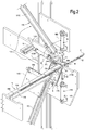
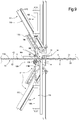
- a machine for introducing a ribbon inside the rings of a chain according to an undulated trend is indicated as a whole with the number 10.
- the chain being processed is indicated as a whole with the letter C, while a ring of the chain is indicated with the letter A.
- the ribbon which can be made of any non-rigid, flaccid material such as fabric, nonwoven fabric, leather, imitation leather, film etc., is indicated as a whole with the letter F.
- the chain C can have flat dimensions, or have an extension, or length, prevalently longitudinal, a transverse width corresponding substantially to the width of a ring A, and a thickness similar to the thickness of a ring or of a pair of rings, in the areas in which two subsequent rings are superimposed.
- the sides of the chain defined by the longitudinal length and by the transverse width, or the opposite "wide" sides of the chain, on which the rings A are open, are defined as "faces" C1 and C2.
- the machine 10 is provided with a frame, not indicated specifically, with which the various components indicated below are associated.
- the machine 10 comprises a sliding guide 11 for the chain C (in Fig. 1 the guide is sectioned along its centerline to allow better viewing), in this example defined by a sliding surface 11A, preferably horizontal or preferably slanting in a single direction, or with normal lying on a vertical plane, and opposite lateral containment edges 11B. These edges 11B can be spaced at a distance from each other to adjust the width of the guide as a function of the width of the chain. Moreover, in other preferred embodiments, the edges are held pushed against the chain, to create a predetermined friction, adjustable, and ensure a particularly precise feed movement.
- the machine 10 also has means 12 for controlled feed of the chain C on the guide 11, which comprise, for example, gripper 13 adapted to clamp the chain C when controlled.
- the gripper 13 is provided downstream with respect to the area of insertion H of the ribbon into the chain with reference to the direction of feed K of the chain (indicated by the arrow marked with K, concordant to the guide 11).
- the gripper 13 is associated with a translation actuator 14, for example a pneumatic cylinder that allows it to move; the gripper is fixed to the actuator 14, for example, by means of a bracket 14A.
- the gripper 13 clamps the chain during the steps of insertion of the ribbon F into the same chain, are then moved (still clamping the chain) by a desired step, for example the distance corresponding to the length of a single ring, drawing with them the chain; the gripper is opened (a pneumatic control member is associated, for example, with the gripper) and returned (again by means of the translation actuator 14) to the preceding position and is then clamped on the chain again.
- a pneumatic control member is associated, for example, with the gripper
- the gripper is always shown open, or not clamping the chain; however, it must be understood that in these figures the gripper clamps the chain, or are closed, just as in the other figures.
- the means 12 for controlled feed of the chain C can also (or alternatively) comprise a rotating reel, motorized, on which the chain with the ribbon inserted is wound (and which can help to pull the chain), not shown in the figures.
- the means 12 for controlled feed of the chain on the guide 11 also comprise a centering and/or retaining abutment 12A placed on the guide 11 upstream of the area of insertion H of the ribbon into the chain.
- This abutment is adapted to be reversibly inserted, when controlled, into a respective ring A3, positioned on the opposite side with respect to the gripper 13 with respect to the area H.
- this abutment is moved by a translation actuator 12B, positioned vertically, so that the abutment 12A, fixed to the actuator, is able to translate inside the ring of the chain, or to withdraw in a position outside the ring, releasing it.
- the machine 10 also comprises means for blocking a part of the ribbon F on the chain C, with the ribbon that is longitudinally facing at least in part the first face C1 of the chain C, so that one end F1 of the ribbon, opposite the direction of feed of the chain (indicated by the arrow marked with K, concordant to the guide 11), is free.
- the gripper 13 presses the ribbon on the chain and, therefore, besides acting as means for movement of the chain, the gripper produces blocking of the ribbon on the chain.
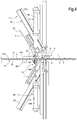
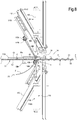
- the machine 10 comprises a first insertion unit 15 adapted to push, in a prima direction (indicated by the arrow Z), in this example a vertical direction from top to bottom, a portion of ribbon F into a first ring A1 of the chain it is facing, to form an increasing eyelet S (or loop) on the opposite face C2 of the first ring A1 with respect to that of insertion, as can be seen in Figs. 1 , 2 , 4 and 5 .
- This first insertion unit 15 is adapted to act until the free end F1 of the ribbon F passes through the first ring A1, reaching the second face C2 of the chain ( Fig. 6 ), or in this example the lower face.
- the first insertion unit 15 comprises a pusher 16, arranged above the guide 11 (with the exception of the final part of its movement through the chain), which has, for example, a translation actuator 16A (for example a pneumatic cylinder) with an insertion end 16B that is moved by the same actuator in direction incident to the faces of the chain, in this example the direction Z orthogonal to the sliding surface 11A of the guide 11.
- a translation actuator 16A for example a pneumatic cylinder
- the insertion end 16B of the pusher 16 encounters the ribbon F that is above the first ring A1, pushes the portion of ribbon inside the ring A1, passing through it, thus creating the eyelet S that increases, on the opposite face, with the travel of this pusher inside the ring, until the pusher is stopped and returned to the initial position, above the first ring ( Figs. 2 , 5 and 6 ).
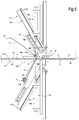
- the first insertion unit 15 also comprises a removal device 17, that has a first inserter 17A, arranged below the guide 11, associated with actuation means that make the inserter movable from a standby position ( Figs. 1 , 3 and 4 ) to a position inserted in the eyelet S formed by the pusher 16. Subsequently, the first inserter 17A is movable in a direction away from the sliding guide 11 ( Figs. 2 , 5 ), drawing with it the part of ribbon not yet inserted in the subsequent rings, so that the eyelet S is enlarged until the free end F1 of the ribbon passes through the ring A1 and the related portion of ribbon, from the first ring A1 is located completely below the chain C, or below the second face C2 thereof.
- a removal device 17 that has a first inserter 17A, arranged below the guide 11, associated with actuation means that make the inserter movable from a standby position ( Figs. 1 , 3 and 4 ) to a position inserted in the eyelet
- the first inserter 17A is associated with a pair of movement actuators 17B and 17C.
- the first actuator 17B for example a pneumatic cylinder, is adapted to move the inserter 17A, for example having a pointed or common end adapted to enter the eyelet S, according to a horizontal direction X or, more in general, according to a direction X incident to a plane parallel to the direction of sliding of the chain and of the two pushers, or in this example a vertical plane.
- the second actuator 17C for example a pneumatic cylinder, is adapted to move the inserter 17A on the aforesaid plane to move away from said guide, preferably with a direction slanting from the guide toward the rear part of the machine, or the part opposite the area of insertion H, or slanting from the top toward the bottom.
- the first actuator 17B is fixed, for example by means of a bracket 17D, to the second actuator 17C, so that this latter moves the assembly formed by the first actuator 17B and by the related inserter 17A, as can be seen in Figs. 2 and 5 .
- the machine 10 also comprises a second insertion unit 115, the same as the first unit 15, but arranged with the related pusher below the guide 11 and functionally overturned with respect to the first unit 15, or arranged symmetrically to the first unit 15 with respect to the guide 11, as can be seen in the figures.
- a second insertion unit 115 the same as the first unit 15, but arranged with the related pusher below the guide 11 and functionally overturned with respect to the first unit 15, or arranged symmetrically to the first unit 15 with respect to the guide 11, as can be seen in the figures.
- the components of the second insertion unit 115 corresponding to the components of the first unit 15 will be indicated with the same reference numerals, increased by 100.
- the pushers 16 and 116 (and more in particular their ends 16B and 116B) of the two units 15 and 115, are mutually aligned, or translate with their operating ends along a same vertical line.
- the second insertion unit 115 is adapted to push, in a second direction 1Z, opposite the first direction Z, the portion of ribbon that has passed through the first ring A1, into a second ring A2 to form an increasing eyelet S2 (or loop) on the second face C1, as can be seen, for example, in Figs. 4 and 5 .
- the second insertion unit 115 is adapted to act until the free end F1 of the ribbon passes through the second ring, returning above the first face of the chain.
- the second insertion unit 115 then has a second removal device 117 with a second inserter 117A moved by two actuators 117B and 117C.
- the machine comprises an electronic control system for the actuators and the various parts, for example a PLC system, not indicated in the figures.
- Operation of the machine is for example given by the following operations managed by the electronic system, preferably performed in sequence:
- the gripper after having been moved forward by one step is opened and releases the chain and the ribbon, and then moved back by one step and closed again to clamp chain and ribbon.
Landscapes
- Engineering & Computer Science (AREA)
- Textile Engineering (AREA)
- Discharge By Other Means (AREA)
Applications Claiming Priority (1)
| Application Number | Priority Date | Filing Date | Title |
|---|---|---|---|
| ITFI20140206 | 2014-09-09 |
Publications (2)
| Publication Number | Publication Date |
|---|---|
| EP2995707A1 EP2995707A1 (en) | 2016-03-16 |
| EP2995707B1 true EP2995707B1 (en) | 2020-07-29 |
Family
ID=51871149
Family Applications (1)
| Application Number | Title | Priority Date | Filing Date |
|---|---|---|---|
| EP15184218.4A Active EP2995707B1 (en) | 2014-09-09 | 2015-09-08 | Machine for introducing a ribbon inside the rings of a chain |
Country Status (2)
| Country | Link |
|---|---|
| EP (1) | EP2995707B1 (es) |
| ES (1) | ES2825651T3 (es) |
Families Citing this family (1)
| Publication number | Priority date | Publication date | Assignee | Title |
|---|---|---|---|---|
| IT202300006081A1 (it) * | 2023-03-29 | 2024-09-29 | Andrea Prezzolini | Macchina per realizzare catene intrecciate con un nastro |
Family Cites Families (2)
| Publication number | Priority date | Publication date | Assignee | Title |
|---|---|---|---|---|
| DE29502252U1 (de) * | 1995-02-11 | 1995-04-27 | Bree Collection GmbH & Co Besitzgesellschaft KG, 30916 Isernhagen | Riemen |
| US5979466A (en) * | 1999-05-05 | 1999-11-09 | Chian Tai Attire Enterprise Co., Ltd. | Barrette |
-
2015
- 2015-09-08 ES ES15184218T patent/ES2825651T3/es active Active
- 2015-09-08 EP EP15184218.4A patent/EP2995707B1/en active Active
Non-Patent Citations (1)
| Title |
|---|
| None * |
Also Published As
| Publication number | Publication date |
|---|---|
| EP2995707A1 (en) | 2016-03-16 |
| ES2825651T3 (es) | 2021-05-17 |
Similar Documents
| Publication | Publication Date | Title |
|---|---|---|
| AU2018267640B2 (en) | Apparatus for laser or plasma cutting of pieces of laminar material wound in coil | |
| DK144366B (da) | Fremgangsmaade og apparat til indhylning og pakning af genstande i folier af straekbart plastmateriale | |
| DE102016012274A1 (de) | Verfahren zum Zuführen von Wäschestücken zu einer Wäscheweiterbehandlungseinrichtung sowie Vorrichtung | |
| EP3225732B1 (en) | Buffering device for automated fabric article loading device | |
| CA3050958C (en) | Method and apparatus for forming a loop | |
| EP2995707B1 (en) | Machine for introducing a ribbon inside the rings of a chain | |
| KR101732299B1 (ko) | 평면의 요소들을 운송하기 위한 디바이스 | |
| EP3519620A1 (de) | Verfahren und vorrichtung zum zuführen von wäschestücken zu einer wäschebehandlungseinrichtung, insbesondere einer mangel | |
| TW201532548A (zh) | 拉鏈組裝裝置 | |
| MXPA02000996A (es) | Aparato para el transporte de una seccion de un producto plano. | |
| RU2626943C2 (ru) | Способ и устройство для транспортировки плоских изделий | |
| EP2993134B1 (en) | Hooding apparatus | |
| CN102691190A (zh) | 导布机 | |
| US4529463A (en) | Process and apparatus for the manufacture of adjustable shoulder-straps for clothing | |
| EP3575483B1 (de) | Verfahren und vorrichtung zum beladen einer klammer mit einem wäschestück, insbesondere einem zu sortierenden wäschestück | |
| EP3643650A1 (de) | Verfahren zum taktweisen vorschub von materialzuschnitten in einer verpackungsmaschine | |
| IT8223873A1 (it) | Procedimento e dispositivo per infilare fibbie su bretelle, ed in particolare bretelle di reggiseni ed altri indumenti intimi ed indumenti | |
| EP0816555A2 (de) | Vorrichtung zum Gruppieren von Textilien | |
| EP3453626B1 (en) | Hooding machine with film storage device | |
| KR101838285B1 (ko) | 원단공급장치 | |
| EP2594497B1 (en) | System for inserting sleeves | |
| KR20250170633A (ko) | 리본이 인터레이스된 체인을 제조하기 위한 기계 | |
| EP3333092A1 (en) | Wrapping machine | |
| US1436306A (en) | Apparatus for attaching belt hooks to belts and the like | |
| JPH0342457A (ja) | 並列テープ群の整列機構 |
Legal Events
| Date | Code | Title | Description |
|---|---|---|---|
| PUAI | Public reference made under article 153(3) epc to a published international application that has entered the european phase |
Free format text: ORIGINAL CODE: 0009012 |
|
| AK | Designated contracting states |
Kind code of ref document: A1 Designated state(s): AL AT BE BG CH CY CZ DE DK EE ES FI FR GB GR HR HU IE IS IT LI LT LU LV MC MK MT NL NO PL PT RO RS SE SI SK SM TR |
|
| AX | Request for extension of the european patent |
Extension state: BA ME |
|
| 17P | Request for examination filed |
Effective date: 20160715 |
|
| RBV | Designated contracting states (corrected) |
Designated state(s): AL AT BE BG CH CY CZ DE DK EE ES FI FR GB GR HR HU IE IS IT LI LT LU LV MC MK MT NL NO PL PT RO RS SE SI SK SM TR |
|
| RIC1 | Information provided on ipc code assigned before grant |
Ipc: D04D 11/00 20060101AFI20191217BHEP Ipc: A45C 13/30 20060101ALN20191217BHEP |
|
| GRAP | Despatch of communication of intention to grant a patent |
Free format text: ORIGINAL CODE: EPIDOSNIGR1 |
|
| STAA | Information on the status of an ep patent application or granted ep patent |
Free format text: STATUS: GRANT OF PATENT IS INTENDED |
|
| INTG | Intention to grant announced |
Effective date: 20200225 |
|
| GRAS | Grant fee paid |
Free format text: ORIGINAL CODE: EPIDOSNIGR3 |
|
| GRAA | (expected) grant |
Free format text: ORIGINAL CODE: 0009210 |
|
| STAA | Information on the status of an ep patent application or granted ep patent |
Free format text: STATUS: THE PATENT HAS BEEN GRANTED |
|
| AK | Designated contracting states |
Kind code of ref document: B1 Designated state(s): AL AT BE BG CH CY CZ DE DK EE ES FI FR GB GR HR HU IE IS IT LI LT LU LV MC MK MT NL NO PL PT RO RS SE SI SK SM TR |
|
| REG | Reference to a national code |
Ref country code: CH Ref legal event code: EP |
|
| REG | Reference to a national code |
Ref country code: AT Ref legal event code: REF Ref document number: 1295911 Country of ref document: AT Kind code of ref document: T Effective date: 20200815 |
|
| REG | Reference to a national code |
Ref country code: IE Ref legal event code: FG4D |
|
| REG | Reference to a national code |
Ref country code: DE Ref legal event code: R096 Ref document number: 602015056424 Country of ref document: DE |
|
| REG | Reference to a national code |
Ref country code: RO Ref legal event code: EPE |
|
| REG | Reference to a national code |
Ref country code: LT Ref legal event code: MG4D |
|
| REG | Reference to a national code |
Ref country code: NL Ref legal event code: MP Effective date: 20200729 |
|
| REG | Reference to a national code |
Ref country code: AT Ref legal event code: MK05 Ref document number: 1295911 Country of ref document: AT Kind code of ref document: T Effective date: 20200729 |
|
| PG25 | Lapsed in a contracting state [announced via postgrant information from national office to epo] |
Ref country code: AT Free format text: LAPSE BECAUSE OF FAILURE TO SUBMIT A TRANSLATION OF THE DESCRIPTION OR TO PAY THE FEE WITHIN THE PRESCRIBED TIME-LIMIT Effective date: 20200729 Ref country code: BG Free format text: LAPSE BECAUSE OF FAILURE TO SUBMIT A TRANSLATION OF THE DESCRIPTION OR TO PAY THE FEE WITHIN THE PRESCRIBED TIME-LIMIT Effective date: 20201029 Ref country code: NO Free format text: LAPSE BECAUSE OF FAILURE TO SUBMIT A TRANSLATION OF THE DESCRIPTION OR TO PAY THE FEE WITHIN THE PRESCRIBED TIME-LIMIT Effective date: 20201029 Ref country code: PT Free format text: LAPSE BECAUSE OF FAILURE TO SUBMIT A TRANSLATION OF THE DESCRIPTION OR TO PAY THE FEE WITHIN THE PRESCRIBED TIME-LIMIT Effective date: 20201130 Ref country code: SE Free format text: LAPSE BECAUSE OF FAILURE TO SUBMIT A TRANSLATION OF THE DESCRIPTION OR TO PAY THE FEE WITHIN THE PRESCRIBED TIME-LIMIT Effective date: 20200729 Ref country code: FI Free format text: LAPSE BECAUSE OF FAILURE TO SUBMIT A TRANSLATION OF THE DESCRIPTION OR TO PAY THE FEE WITHIN THE PRESCRIBED TIME-LIMIT Effective date: 20200729 Ref country code: GR Free format text: LAPSE BECAUSE OF FAILURE TO SUBMIT A TRANSLATION OF THE DESCRIPTION OR TO PAY THE FEE WITHIN THE PRESCRIBED TIME-LIMIT Effective date: 20201030 Ref country code: LT Free format text: LAPSE BECAUSE OF FAILURE TO SUBMIT A TRANSLATION OF THE DESCRIPTION OR TO PAY THE FEE WITHIN THE PRESCRIBED TIME-LIMIT Effective date: 20200729 Ref country code: HR Free format text: LAPSE BECAUSE OF FAILURE TO SUBMIT A TRANSLATION OF THE DESCRIPTION OR TO PAY THE FEE WITHIN THE PRESCRIBED TIME-LIMIT Effective date: 20200729 |
|
| PG25 | Lapsed in a contracting state [announced via postgrant information from national office to epo] |
Ref country code: IS Free format text: LAPSE BECAUSE OF FAILURE TO SUBMIT A TRANSLATION OF THE DESCRIPTION OR TO PAY THE FEE WITHIN THE PRESCRIBED TIME-LIMIT Effective date: 20201129 Ref country code: PL Free format text: LAPSE BECAUSE OF FAILURE TO SUBMIT A TRANSLATION OF THE DESCRIPTION OR TO PAY THE FEE WITHIN THE PRESCRIBED TIME-LIMIT Effective date: 20200729 Ref country code: RS Free format text: LAPSE BECAUSE OF FAILURE TO SUBMIT A TRANSLATION OF THE DESCRIPTION OR TO PAY THE FEE WITHIN THE PRESCRIBED TIME-LIMIT Effective date: 20200729 Ref country code: LV Free format text: LAPSE BECAUSE OF FAILURE TO SUBMIT A TRANSLATION OF THE DESCRIPTION OR TO PAY THE FEE WITHIN THE PRESCRIBED TIME-LIMIT Effective date: 20200729 |
|
| PG25 | Lapsed in a contracting state [announced via postgrant information from national office to epo] |
Ref country code: NL Free format text: LAPSE BECAUSE OF FAILURE TO SUBMIT A TRANSLATION OF THE DESCRIPTION OR TO PAY THE FEE WITHIN THE PRESCRIBED TIME-LIMIT Effective date: 20200729 |
|
| REG | Reference to a national code |
Ref country code: DE Ref legal event code: R119 Ref document number: 602015056424 Country of ref document: DE |
|
| PG25 | Lapsed in a contracting state [announced via postgrant information from national office to epo] |
Ref country code: IT Free format text: LAPSE BECAUSE OF FAILURE TO SUBMIT A TRANSLATION OF THE DESCRIPTION OR TO PAY THE FEE WITHIN THE PRESCRIBED TIME-LIMIT Effective date: 20200729 Ref country code: DK Free format text: LAPSE BECAUSE OF FAILURE TO SUBMIT A TRANSLATION OF THE DESCRIPTION OR TO PAY THE FEE WITHIN THE PRESCRIBED TIME-LIMIT Effective date: 20200729 Ref country code: CZ Free format text: LAPSE BECAUSE OF FAILURE TO SUBMIT A TRANSLATION OF THE DESCRIPTION OR TO PAY THE FEE WITHIN THE PRESCRIBED TIME-LIMIT Effective date: 20200729 Ref country code: EE Free format text: LAPSE BECAUSE OF FAILURE TO SUBMIT A TRANSLATION OF THE DESCRIPTION OR TO PAY THE FEE WITHIN THE PRESCRIBED TIME-LIMIT Effective date: 20200729 Ref country code: SM Free format text: LAPSE BECAUSE OF FAILURE TO SUBMIT A TRANSLATION OF THE DESCRIPTION OR TO PAY THE FEE WITHIN THE PRESCRIBED TIME-LIMIT Effective date: 20200729 Ref country code: MC Free format text: LAPSE BECAUSE OF FAILURE TO SUBMIT A TRANSLATION OF THE DESCRIPTION OR TO PAY THE FEE WITHIN THE PRESCRIBED TIME-LIMIT Effective date: 20200729 |
|
| REG | Reference to a national code |
Ref country code: CH Ref legal event code: PL |
|
| REG | Reference to a national code |
Ref country code: ES Ref legal event code: FG2A Ref document number: 2825651 Country of ref document: ES Kind code of ref document: T3 Effective date: 20210517 |
|
| PG25 | Lapsed in a contracting state [announced via postgrant information from national office to epo] |
Ref country code: AL Free format text: LAPSE BECAUSE OF FAILURE TO SUBMIT A TRANSLATION OF THE DESCRIPTION OR TO PAY THE FEE WITHIN THE PRESCRIBED TIME-LIMIT Effective date: 20200729 |
|
| PLBE | No opposition filed within time limit |
Free format text: ORIGINAL CODE: 0009261 |
|
| STAA | Information on the status of an ep patent application or granted ep patent |
Free format text: STATUS: NO OPPOSITION FILED WITHIN TIME LIMIT |
|
| REG | Reference to a national code |
Ref country code: BE Ref legal event code: MM Effective date: 20200930 |
|
| GBPC | Gb: european patent ceased through non-payment of renewal fee |
Effective date: 20201029 |
|
| PG25 | Lapsed in a contracting state [announced via postgrant information from national office to epo] |
Ref country code: SK Free format text: LAPSE BECAUSE OF FAILURE TO SUBMIT A TRANSLATION OF THE DESCRIPTION OR TO PAY THE FEE WITHIN THE PRESCRIBED TIME-LIMIT Effective date: 20200729 Ref country code: LU Free format text: LAPSE BECAUSE OF NON-PAYMENT OF DUE FEES Effective date: 20200908 |
|
| 26N | No opposition filed |
Effective date: 20210430 |
|
| PG25 | Lapsed in a contracting state [announced via postgrant information from national office to epo] |
Ref country code: DE Free format text: LAPSE BECAUSE OF NON-PAYMENT OF DUE FEES Effective date: 20210401 |
|
| PG25 | Lapsed in a contracting state [announced via postgrant information from national office to epo] |
Ref country code: SI Free format text: LAPSE BECAUSE OF FAILURE TO SUBMIT A TRANSLATION OF THE DESCRIPTION OR TO PAY THE FEE WITHIN THE PRESCRIBED TIME-LIMIT Effective date: 20200729 Ref country code: GB Free format text: LAPSE BECAUSE OF NON-PAYMENT OF DUE FEES Effective date: 20201029 Ref country code: LI Free format text: LAPSE BECAUSE OF NON-PAYMENT OF DUE FEES Effective date: 20200930 Ref country code: IE Free format text: LAPSE BECAUSE OF NON-PAYMENT OF DUE FEES Effective date: 20200908 Ref country code: CH Free format text: LAPSE BECAUSE OF NON-PAYMENT OF DUE FEES Effective date: 20200930 Ref country code: BE Free format text: LAPSE BECAUSE OF NON-PAYMENT OF DUE FEES Effective date: 20200930 |
|
| PG25 | Lapsed in a contracting state [announced via postgrant information from national office to epo] |
Ref country code: TR Free format text: LAPSE BECAUSE OF FAILURE TO SUBMIT A TRANSLATION OF THE DESCRIPTION OR TO PAY THE FEE WITHIN THE PRESCRIBED TIME-LIMIT Effective date: 20200729 Ref country code: MT Free format text: LAPSE BECAUSE OF FAILURE TO SUBMIT A TRANSLATION OF THE DESCRIPTION OR TO PAY THE FEE WITHIN THE PRESCRIBED TIME-LIMIT Effective date: 20200729 Ref country code: CY Free format text: LAPSE BECAUSE OF FAILURE TO SUBMIT A TRANSLATION OF THE DESCRIPTION OR TO PAY THE FEE WITHIN THE PRESCRIBED TIME-LIMIT Effective date: 20200729 |
|
| PG25 | Lapsed in a contracting state [announced via postgrant information from national office to epo] |
Ref country code: MK Free format text: LAPSE BECAUSE OF FAILURE TO SUBMIT A TRANSLATION OF THE DESCRIPTION OR TO PAY THE FEE WITHIN THE PRESCRIBED TIME-LIMIT Effective date: 20200729 |
|
| PGFP | Annual fee paid to national office [announced via postgrant information from national office to epo] |
Ref country code: FR Payment date: 20250925 Year of fee payment: 11 |
|
| PGFP | Annual fee paid to national office [announced via postgrant information from national office to epo] |
Ref country code: RO Payment date: 20250825 Year of fee payment: 11 |
|
| PGFP | Annual fee paid to national office [announced via postgrant information from national office to epo] |
Ref country code: ES Payment date: 20251008 Year of fee payment: 11 |