EP2996263B1 - Verfahren und system zur implementierung von kommunikation im sichtbaren licht, sendevorrichtung und empfangsvorrichtung - Google Patents
Verfahren und system zur implementierung von kommunikation im sichtbaren licht, sendevorrichtung und empfangsvorrichtung Download PDFInfo
- Publication number
- EP2996263B1 EP2996263B1 EP13883909.7A EP13883909A EP2996263B1 EP 2996263 B1 EP2996263 B1 EP 2996263B1 EP 13883909 A EP13883909 A EP 13883909A EP 2996263 B1 EP2996263 B1 EP 2996263B1
- Authority
- EP
- European Patent Office
- Prior art keywords
- signal
- constellation
- luminescent light
- light source
- modulation
- Prior art date
- Legal status (The legal status is an assumption and is not a legal conclusion. Google has not performed a legal analysis and makes no representation as to the accuracy of the status listed.)
- Not-in-force
Links
- 238000004891 communication Methods 0.000 title claims description 32
- 238000000034 method Methods 0.000 title claims description 27
- 238000013507 mapping Methods 0.000 claims description 97
- 230000003287 optical effect Effects 0.000 claims description 73
- 238000012545 processing Methods 0.000 claims description 43
- 238000007781 pre-processing Methods 0.000 claims description 24
- 238000010586 diagram Methods 0.000 claims description 19
- 238000006243 chemical reaction Methods 0.000 claims description 10
- 239000011159 matrix material Substances 0.000 claims description 9
- 238000007493 shaping process Methods 0.000 claims description 9
- 230000010363 phase shift Effects 0.000 claims description 6
- 238000005516 engineering process Methods 0.000 description 5
- 238000000926 separation method Methods 0.000 description 4
- 230000005540 biological transmission Effects 0.000 description 3
- 238000013459 approach Methods 0.000 description 1
- 239000013256 coordination polymer Substances 0.000 description 1
- 230000001419 dependent effect Effects 0.000 description 1
- 238000003780 insertion Methods 0.000 description 1
- 230000037431 insertion Effects 0.000 description 1
- 238000011160 research Methods 0.000 description 1
- 239000004065 semiconductor Substances 0.000 description 1
- 238000004088 simulation Methods 0.000 description 1
Images

Classifications
-
- H—ELECTRICITY
- H04—ELECTRIC COMMUNICATION TECHNIQUE
- H04B—TRANSMISSION
- H04B10/00—Transmission systems employing electromagnetic waves other than radio-waves, e.g. infrared, visible or ultraviolet light, or employing corpuscular radiation, e.g. quantum communication
- H04B10/11—Arrangements specific to free-space transmission, i.e. transmission through air or vacuum
- H04B10/114—Indoor or close-range type systems
- H04B10/116—Visible light communication
-
- H—ELECTRICITY
- H04—ELECTRIC COMMUNICATION TECHNIQUE
- H04B—TRANSMISSION
- H04B10/00—Transmission systems employing electromagnetic waves other than radio-waves, e.g. infrared, visible or ultraviolet light, or employing corpuscular radiation, e.g. quantum communication
- H04B10/50—Transmitters
- H04B10/516—Details of coding or modulation
- H04B10/548—Phase or frequency modulation
- H04B10/556—Digital modulation, e.g. differential phase shift keying [DPSK] or frequency shift keying [FSK]
- H04B10/5561—Digital phase modulation
-
- H—ELECTRICITY
- H04—ELECTRIC COMMUNICATION TECHNIQUE
- H04L—TRANSMISSION OF DIGITAL INFORMATION, e.g. TELEGRAPHIC COMMUNICATION
- H04L27/00—Modulated-carrier systems
- H04L27/32—Carrier systems characterised by combinations of two or more of the types covered by groups H04L27/02, H04L27/10, H04L27/18 or H04L27/26
- H04L27/34—Amplitude- and phase-modulated carrier systems, e.g. quadrature-amplitude modulated carrier systems
Definitions
- the present invention relates to the visible light communication technology, and particularly, to a method and system for implementing visible light communication, a sending apparatus and a receiving apparatus.
- the wireless communication technology using the visible light has attracted attention from the academic circles and industrial circles in recent years.
- the lighting equipment using light-emitting elements such as a light emitting diode (LED) and so on
- LED light emitting diode
- the feasibility research on using a semiconductor LED to implement the visible light communication covered by the wireless communication network is ongoing.
- the appropriate approach of combining the visible light communication with a wireless sensor network, a wireless local area network (WLAN) and a power-line communication system is also in the discussion. It has been able to prove that such communication mode will be one of the alternative short-distance and ultra-wideband communication modes in the future.
- the influence on the human body or medical apparatus should be considered, and the LED has been regarded as the most powerful candidate light-emitting device at present. Meanwhile, in the optical communication, a data rate is dependent on a response speed of the light-emitting device. Therefore, a light-emitting device with the higher-speed response performance such as a laser diode (LD) or a super luminescent diode (SLD) also attracts much attention.
- LD laser diode
- SLD super luminescent diode
- the basic principle of implementing the visible light communication is that: a certain kind of modulation such as pulse width modulation (PWM), pulse position/frequency modulation (PPM) or pulse amplitude modulation (PAM) is performed on the light emitted by the light-emitting device; the modulated light energy is used as data to be transmitted, and transmitted through a spatial channel and received by a photoelectric detector (a sensor) on the target device; and the photoelectric detector converts the received optical signal into an electrical signal and then demodulates the sent data through the follow-up processing.
- the target device can be a common portable device attached with such function of transmitting the data through the visible light, such as a mobile phone, a digital camera and a notebook computer and so on. Similar to the constitution of the wireless local area network, the portable terminals constitute the nodes in the network, that is, the visible light communication technology can serve as the local area network technology or the underlying technology applied in an access network.
- the multiple input multiple output (MIMO) may become the mainstream application mode in various scenarios.
- various portable devices equipped with cameras It is not difficult to imagine that using various LEDs as an information releasing system and various portable/mobile terminals as a receiving system is a simple and convenient communication mode.
- the document “ CN102684819A” discloses a data transmission method, which includes: A transmitter performs scrambling, constellation modulation, and multiple-input multiple-output precoding processing sequentially on downlink user data to obtain a precoded symbol sequence; performs time-frequency resource mapping on the precoded symbol sequence to obtain frequency domain data of an OFDM symbol; performs conjugate symmetric extension and IFFT on the frequency domain data of the OFDM symbol to obtain a time domain real-number sequence; performs CP insertion processing on the time domain real-number sequence to form a first downlink time domain baseband signal; loads the first downlink time domain baseband signal onto a direct current of a LED lighting circuit to form a LED driving electrical signal; and converts the LED driving electrical signal into a visible beam of the LED for transmission.
- the present invention provides a method and system for implementing visible light communication, a sending apparatus and a receiving apparatus, which can implement the visible light communication, to meet the demand for application scenarios of the visible light in the future.
- the present invention discloses a method for implementing visible light communication, which comprises: after performing constellation modulation on data to be sent, a sending end mapping a modulated signal to a corresponding luminescent light source; and transmitting the data to be sent to a receiving end through an optical signal, and the receiving end converting the received optical signal into an electrical signal; and the receiving end determining a constellation modulation signal according to a luminescent light source corresponding to the received signal, and demodulating the constellation modulation signal to obtain received data.
- it further comprises: performing encoding on the data to be sent, and performing constellation modulation on an encoded signal.
- mapping a modulated signal to a corresponding luminescent light source comprises: mapping a signal of a constellation point on which the constellation modulation is performed to a luminescent light source corresponding to the constellation point, according to the mapping relationship.
- said transmitting the data to be sent to a receiving end through an optical signal comprises: opening the corresponding luminescent light source, and transmitting the data to be sent to the receiving end through the optical signal.
- said opening the corresponding luminescent light source comprises: driving the electrical signal on which the constellation modulation is performed, and opening a luminescent light source on a constellation point corresponding to the modulated signal.
- the method further comprises: performing filter shaping processing on the electrical signal obtained through the conversion.
- the method further comprises: pre-positioning a location of the luminescent light source in a constellation diagram.
- the pre-positioning comprises: the sending end simultaneously opening all luminescent light sources corresponding to constellation modulation in different modulation modes, or simultaneously opening luminescent light sources in part of particular locations; and the receiving end identifying a location of each luminescent light source corresponding to each constellation point in different modulation modes by positioning a light source matrix, and establishing a mapping relationship between a constellation modulation signal and a location where the luminescent light source is located consistent with that of the sending end.
- determining a constellation modulation signal according to the luminescent light source corresponding to the received signal comprises: according to the established mapping relationship, mapping a location of the luminescent light source where the received optical signal is located to a constellation modulation signal corresponding to the constellation point.
- the present invention further provides a system for implementing visible light communication, which comprises: a sending end and a receiving end; the sending end is configured to: after performing constellation modulation on data to be sent, map a modulated signal to a corresponding luminescent light source; and transmit the data to be sent to the receiving end through an optical signal; and the receiving end is configured to: receive the optical signal from the sending end and convert the optical signal into an electrical signal; and determine a constellation modulation signal according to a luminescent light source corresponding to the received signal, and demodulate the constellation modulation signal to obtain received data.
- the sending end at least comprises: a signal preprocessing unit, a mapping unit and a signal output unit, wherein, the signal preprocessing unit is configured to: perform preprocessing on the data to be sent and then output the preprocessed data to be sent to the mapping unit, wherein the preprocessing comprises encoding and constellation modulation; the mapping unit is configured to: be set with a mapping relationship between a constellation modulation signal and a location where the luminescent light source is located; and map the modulated signal to the corresponding luminescent light source according to the set mapping relationship and then output the modulated signal to the signal output unit; and the signal output unit is configured to: convert an electrical signal from the mapping unit into an optical signal, and transmit the optical signal obtained through the conversion to the receiving end.
- the signal preprocessing unit is configured to: perform preprocessing on the data to be sent and then output the preprocessed data to be sent to the mapping unit, wherein the preprocessing comprises encoding and constellation modulation
- the mapping unit is configured to: be set with a mapping
- the luminescent light source is independent, or is a luminescent point independently opened in a luminescent panel.
- the receiving terminal at least comprises: a signal receiving unit, an inverse mapping unit and a signal processing unit, wherein, the signal receiving unit is configured to: convert the optical signal from the sending end into the electrical signal and then output the electrical signal to the inverse mapping unit; the inverse mapping unit is configured to: according to an established mapping relationship between a constellation modulation signal and a location where the luminescent light source is located, map a location of the luminescent light source where the received optical signal is located into a constellation modulation signal corresponding to a constellation point, and output the obtained constellation modulation signal to the signal processing unit; and the signal processing unit is configured to: perform processing on the constellation modulation signal from the inverse mapping unit to obtain the data sent by the sending end; wherein the processing comprises modulation and decoding.
- the signal receiving unit is configured to: convert the optical signal from the sending end into the electrical signal and then output the electrical signal to the inverse mapping unit
- the inverse mapping unit is configured to: according to an established mapping relationship between a constellation modulation signal and a location where the lumin
- the signal receiving unit is further configured to: perform filter shaping processing on the received optical signal.
- the sending end is further configured to: simultaneously open all luminescent light sources corresponding to constellation modulation in different modulation modes, or simultaneously open luminescent light sources in part of particular locations; the receiving end is further configured to: identify a location of each luminescent light source corresponding to each constellation point in different modulation modes by positioning a light source matrix, and establish a mapping relationship between a constellation modulation signal and a location where the luminescent light source is located consistent with that of the sending end.
- a number of the luminescent light sources is 4; when the constellation modulation is quadrature amplitude modulation with 16 kinds of symbols (16QAM), a number of the luminescent light sources is 16; and when the constellation modulation is quadrature amplitude modulation with 64 kinds of symbols (64QAM), a number of the luminescent light sources is 64.
- QPSK quadternary phase shift keying
- the present invention further provides a sending apparatus, which is configured to: after performing constellation modulation on data to be sent, map a modulated signal to a corresponding luminescent light source; and send the data to be sent throughan optical signal.
- the sending apparatus at least comprises: a signal preprocessing unit, a mapping unit and a signal output unit, wherein, the signal preprocessing unit is configured to: perform preprocessing on the data to be sent and then output the preprocessed data to be sent to the mapping unit, wherein the preprocessing comprises encoding and constellation modulation; the mapping unit is configured to: be set with a mapping relationship between a constellation modulation signal and a location where the luminescent light source is located; and map the modulated signal to the corresponding luminescent light source according to the set mapping relationship and then output the modulated signal to the signal output unit; and the signal output unit is configured to: convert an electrical signal from the mapping unit into an optical signal, and transmit the optical signal obtained through the conversion to a receiving end.
- the signal preprocessing unit is configured to: perform preprocessing on the data to be sent and then output the preprocessed data to be sent to the mapping unit, wherein the preprocessing comprises encoding and constellation modulation
- the mapping unit is configured to: be set with a
- the sending apparatus is further configured to: simultaneously open all luminescent light sources corresponding to constellation modulation in different modulation mode, or simultaneously open luminescent light sources in part of particular locations.
- the constellation modulation is quaternary phase shift keying (QPSK) signal modulation
- a number of the luminescent light sources is 4;
- the constellation modulation is quadrature amplitude modulation with 16 kinds of symbols (16QAM), a number of the luminescent light sources is 16; and
- the constellation modulation is quadrature amplitude modulation with 64 kinds of symbols (64QAM), a number of the luminescent light sources is 64.
- the present invention further provides a receiving apparatus, which is configured to: convert a received optical signal into an electrical signal; and determine a constellation modulation signal according to a luminescent light source corresponding to the received signal, and demodulate the constellation modulation signal to obtain received data.
- the receiving apparatus at least comprises: a signal receiving unit, an inverse mapping unit and a signal processing unit, wherein, the signal receiving unit is configured to: convert an optical signal from a sending end into an electrical signal and then output the electrical signal to the inverse mapping unit; the inverse mapping unit is configured to: according to an established mapping relationship between a constellation modulation signal and a location where the luminescent light source is located, map a location of the luminescent light source where the received optical signal is located to a constellation modulation signal corresponding to a constellation point, and output the obtained constellation modulation signal to the signal processing unit; and the signal processing unit is configured to: perform processing on the constellation modulation signal from the inverse mapping unit to obtain the data sent by the sending end; wherein the processing comprises modulation and decoding.
- the signal receiving unit is configured to: convert an optical signal from a sending end into an electrical signal and then output the electrical signal to the inverse mapping unit
- the inverse mapping unit is configured to: according to an established mapping relationship between a constellation modulation signal and a location where the
- the signal receiving unit is further configured to: perform filter shaping processing on the received optical signal.
- the receiving apparatus is further configured to: identify a location of each luminescent light source corresponding to each constellation point in different modulation modes by positioning a light source matrix, and establish a mapping relationship between a constellation modulation signal and a location where the luminescent light source is located consistent with that of a sending apparatus.
- the technical scheme of the present application comprises: after performing constellation modulation on data to be sent, a sending end mapping a modulated signal to a corresponding luminescent light source; and transmitting the data to be sent to a receiving end through an optical signal, and the receiving end converting a received optical signal into an electrical signal; and the receiving end determining a constellation modulation signal according to a luminescent light source corresponding to the received signal, and demodulating the constellation modulation signal to obtain received data.
- the sending end places light sources of the visible light according a constellation diagram form of the constellation modulation, and maps the signal obtained after the constellation modulation is performed on the data to be sent to a luminescent light source corresponding to the location of the constellation point and drives the luminescent light source, thereby transmitting the data to be sent to the receiving end through the optical signal; and the receiving terminal determines a constellation modulation signal corresponding to the constellation point according to the location of the luminescent light source, to acquire the data from the sending end.
- the visible light communication is implemented, which meets the demand for application scenarios of the visible light in the future.
- FIG. 1 is a flow chart of a method for implementing visible light communication according to the present invention, and as shown in FIG. 1 , the following steps are included.
- step 100 after performing constellation modulation on data to be sent, a sending end maps a modulated signal to a corresponding luminescent light source.
- luminescent light sources of the visible light are placed in simulation to the form of locations of the constellation points after the constellation modulation is performed, and a mapping relationship between a constellation modulation signal and a location where the luminescent light source is located is preset.
- QPSK quaternary phase shift keying
- 4 constellation points can be generated, and thus 4 luminescent light sources are required to correspond to the 4 constellation points respectively;
- quadrature amplitude modulation with 16 kinds of symbols (16QAM) is a 4bit byte and the 16QAM modulation is adopted, 16 constellation points can be generated, and thus 16 luminescent light sources are required to correspond to the 16 constellation points respectively;
- quadrature amplitude modulation with 64 kinds of symbols 64QAM
- 64QAM quadrature amplitude modulation with 64 kinds of symbols
- 2 n luminescent light sources can transmit n-byte constellation modulation information at each moment, and during the data transmission, the luminescent light source corresponding to only one constellation point is opened at each moment.
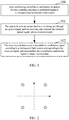
- FIG. 2 is a first implementation schematic diagram of a corresponding relationship between locations of light sources and a constellation diagram according to the present invention
- the constellation modulation is the QPSK modulation in FIG. 2
- the placement locations of the luminescent light sources are as shown in FIG. 2
- double-loop circles represent 4 luminescent light sources respectively corresponding to different constellation points in the FIG. 2
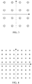
- FIG. 3 is a second implementation schematic diagram of a corresponding relationship between locations of light sources and a constellation diagram according to the present invention
- the constellation modulation is the 16QAM modulation in FIG. 3
- the placement locations of the luminescent light sources are as shown in FIG. 3
- double-loop circles represent 16 luminescent light sources respectively corresponding to different constellation points in the FIG. 3.
- FIG. 4 is a third implementation schematic diagram of a corresponding relationship between locations of light sources and a constellation diagram according to the present invention
- the constellation modulation is the 64QAM modulation in FIG. 4
- the placement locations of the luminescent light sources are as shown in FIG. 4
- double-loop circles represent 64 luminescent light sources respectively corresponding to different constellation points in the FIG. 4 .
- each luminescent light source can be independent, and it also can be a luminescent point that can be independently opened in a luminescent panel. It should be noted that a separation distance between the luminescent points is required to satisfy that the receiving end can identify different luminescent points, and with respect to how to specifically determine the separation distance between the luminescent points, it should be easily implemented by the people skilled in the art according to the actual conditions, which is not limited here.
- mapping the modulated signal to the corresponding luminescent light source includes: according to the preset mapping relationship between the constellation modulation signal and the location where the luminescent light source is located, mapping a signal of a constellation point on which the constellation modulation is currently performed to a luminescent light source corresponding to the constellation point. After the constellation modulation is performed, a throughput of transmitting data streams becomes n times of not performing the constellation modulation.
- step before performing constellation modulation on the data to be sent, it further includes: performing encoding on the data to be sent, and performing constellation modulation on an encoded signal.
- the specific implementation of the encoding and constellation modulation belongs to the common technical means of the people skilled in the art, which will not be repeated here.
- step 101 the data to be sent are transmitted to a receiving end through an optical signal, and the receiving end converts the received optical signal into an electrical signal.
- transmitting the data to be sent to the receiving end through the optical signal includes: opening the corresponding luminescent light source, and transmitting the data to be sent to the receiving end through the optical signal.
- opening the corresponding luminescent light source specifically includes: driving the electrical signal on which the constellation modulation is performed, and opening a luminescent light source on a constellation point corresponding to the modulated signal, thereby completing a conversion from the electrical signal to the optical signal.
- the receiving terminal converting the received optical signal into the electrical signal belongs to the common technical means of the people skilled in the art, and the specific implementation thereof is not used to limit the protection scope of the present invention, which will not be repeated here.
- the receiving terminal converts the received optical signal into the electrical signal, it further includes: performing filter shaping processing on the electrical signal obtained through conversion.
- the specific implementation belongs to the common technical means of the people skilled in the art, which is not used to limit the protection scope of the present invention, and will not be repeated here.
- step 102 the receiving end determines a constellation modulation signal according to a luminescent light source corresponding to the received signal, and demodulates the constellation modulation signal to obtain received data.
- the method also includes: pre-positioning a location of the luminescent light source in a constellation diagram. That is to say, before the communication, the sending end simultaneously opens all luminescent light sources corresponding to constellation modulation in different modulation modes (or simultaneously opens luminescent light sources in part of particular locations), and the receiving end identifies a location of each luminescent light source corresponding to each constellation point in different modulation modes by positioning a light source matrix, thereby establishing a mapping relationship between a constellation modulation signal and a location where the luminescent light source is located consistent with that of the sending end at the receiving end.
- determining the constellation modulation signal according to the luminescent light source corresponding to the received signal in the step includes: mapping a location of the luminescent light source where the received optical signal is located to a constellation modulation signal corresponding to the constellation point according to the established mapping relationship between the constellation modulation signal and the location where the luminescent light source is located.
- processing including demodulation and decoding, etc. is performed on the mapped constellation modulation signal on the constellation point to obtain the received data.
- the specific implementation belongs to the common technical means of the people skilled in the art, which will not be repeated here.
- the sending end places light sources of the visible light according a constellation diagram form of the constellation modulation, and maps the signal obtained after the constellation modulation is performed on the data to be sent to a luminescent light source corresponding to the location of the constellation point and drives the luminescent light source, thereby transmitting the data to be sent to the receiving end through the optical signal; and the receiving terminal determines a constellation modulation signal corresponding to the constellation point according to the location of the luminescent light source, to acquire the data from the sending end.
- the visible light communication is implemented, which meets the demand for application scenarios of the visible light in the future.
- the present invention also provides a system for implementing visible light communication, and as shown in FIG. 5 , a sending end and a receiving end are included, wherein, the sending end is configured to: after performing constellation modulation on data to be sent, map a modulated signal to a corresponding luminescent light source; and transmit the data to be sent to the receiving end through an optical signal; and the receiving end is configured to: receive the optical signal from the sending end and convert the optical signal into an electrical signal; and determine a constellation modulation signal according to a luminescent light source corresponding to the received signal, and demodulate the constellation modulation signal to obtain received data.
- the sending end is configured to: after performing constellation modulation on data to be sent, map a modulated signal to a corresponding luminescent light source; and transmit the data to be sent to the receiving end through an optical signal
- the receiving end is configured to: receive the optical signal from the sending end and convert the optical signal into an electrical signal; and determine a constellation modulation signal according to a luminescent light source corresponding to the
- the sending end at least includes: a signal preprocessing unit, a mapping unit and a signal output unit, wherein, the signal preprocessing unit is configured to: perform preprocessing on the data to be sent and then output the data to be sent to the mapping unit, wherein the preprocessing can include encoding and constellation modulation; the mapping unit, in which a mapping relationship between a constellation modulation signal and a location where the luminescent light source is located is set, is configured to: according to the set mapping relationship, map the modulated signal to the corresponding luminescent light source and then output the modulated signal to the signal output unit; and the signal output unit is configured to: convert an electrical signal from the mapping unit into an optical signal, and transmit the optical signal obtained through conversion to the receiving end.
- the signal preprocessing unit is configured to: perform preprocessing on the data to be sent and then output the data to be sent to the mapping unit, wherein the preprocessing can include encoding and constellation modulation
- the mapping unit in which a mapping relationship between a constellation modulation signal and
- each luminescent light source can be independent, and it also can be a luminescent point that can be independently opened in a luminescent panel. It should be noted that a separation distance between the luminescent points is required to satisfy that the receiving end can identify different luminescent points, and with respect to how to specifically determine the separation distance between the luminescent points, it should be easily implemented by the people skilled in the art according to the actual conditions, which is not limited here.
- the receiving terminal at least includes: a signal receiving unit, an inverse mapping unit and a signal processing unit, wherein, the signal receiving unit is configured to: convert the optical signal from the sending end into the electrical signal and then output the electrical signal to the inverse mapping unit; and it is further configured to perform filter shaping processing on the received optical signal.
- the inverse mapping unit is used to: according to an established mapping relationship between a constellation modulation signal and a location where the luminescent light source is located, map a location of the luminescent light source where the received optical signal is located to a constellation modulation signal corresponding to a constellation point, and output the obtained constellation modulation signal to the signal processing unit; and the signal processing unit is configured to: perform processing on the constellation modulation signal from the inverse mapping unit to obtain the data sent by the sending end.
- the processing therein includes modulation and decoding and so on.
- the sending end is also configured to: simultaneously open all luminescent light sources corresponding to constellation modulation in different modulation modes, or simultaneously open luminescent light sources in part of particular locations; the receiving end is also configured to: identify a location of each luminescent light source corresponding to each constellation point in different modulation modes by positioning a light source matrix, and establish a mapping relationship between a constellation modulation signal and a location where the luminescent light source is located consistent with that of the sending end.
- location calibration such as a plurality of location possibilities corresponding to the QPSK, 16QAM and 64QAM modulation modes shown in FGI. 2 to FIG. 4 , the receiving end is just required to indentify the location by positioning the light source matrix.
- the specific implementation belongs to the common knowledge of the people skilled in the art, which is not used to limit the protection scope of the present invention.
- the number of the luminescent light sources is 4; when the constellation modulation is quadrature amplitude modulation with 16 kinds of symbols (16QAM), the number of the luminescent light sources is 16; and when the constellation modulation is quadrature amplitude modulation with 64 kinds of symbols (64QAM), the number of the luminescent light sources is 64.
- QPSK quadrature phase shift keying
- the present invention also provides a sending apparatus for implementing visible light communication, which is configured to: after performing constellation modulation on data to be sent, map a modulated signal to a corresponding luminescent light source; and send the data to be sent by means of optical signal.
- a signal preprocessing unit, a mapping unit and a signal output unit are at least included, wherein, the signal preprocessing unit is configured to: perform preprocessing on the data to be sent and then output the data to be sent to the mapping unit, wherein the preprocessing can include encoding and constellation modulation;
- the mapping unit in which a mapping relationship between a constellation modulation signal and a location where the luminescent light source is located is set, is configured to: map the modulated signal to the corresponding luminescent light source according to the set mapping relationship and then output the modulated signal to the signal output unit; and the signal output unit is configured to: convert an electrical signal from the mapping unit into an optical signal, and transmit the optical signal obtained through conversion to a receiving end.
- the sending apparatus is also configured to: simultaneously open all luminescent light sources corresponding to constellation modulation in different modulation modes, or simultaneously open luminescent light sources in part of particular locations.
- the present invention also provides a receiving apparatus for implementing visible light communication, which is configured to: convert a received optical signal into an electrical signal; and determine a constellation modulation signal according to a luminescent light source corresponding to the received signal, and demodulate the constellation modulation signal to obtain received data.
- a signal receiving unit, an inverse mapping unit and a signal processing unit are at least included, wherein, the signal receiving unit is configured to: convert an optical signal from a sending end into an electrical signal and then output the electrical signal to the inverse mapping unit; and it is further configured to perform filter shaping processing on the received optical signal.
- the inverse mapping unit is configured to: according to an established mapping relationship between a constellation modulation signal and a location where the luminescent light source is located, map a location of the luminescent light source where the received optical signal is located to a constellation modulation signal corresponding to a constellation point, and output the obtained constellation modulation signal to the signal processing unit; and the signal processing unit is configured to: perform processing on the constellation modulation signal from the inverse mapping unit to obtain the data sent by the sending end.
- the processing therein includes modulation and decoding and so on.
- the receiving apparatus is also configured to: by recording a location of each luminescent light source corresponding to each constellation point in different modulation modes, establish a mapping relationship between a constellation modulation signal and a location where the luminescent light source is located consistent with that of the sending apparatus.
- the sending end places light sources of the visible light according a constellation diagram form of the constellation modulation, and maps the signal obtained after the constellation modulation is performed on the data to be sent to a luminescent light source corresponding to the location of the constellation point and drives the luminescent light source, thereby transmitting the data to be sent to the receiving end through the optical signal; and the receiving terminal determines a constellation modulation signal corresponding to the constellation point according to the location of the luminescent light source, to acquire the data from the sending end.
- the visible light communication is implemented, which meets the demand for application scenarios of the visible light in the future.
Landscapes
- Physics & Mathematics (AREA)
- Electromagnetism (AREA)
- Engineering & Computer Science (AREA)
- Computer Networks & Wireless Communication (AREA)
- Signal Processing (AREA)
- Optical Communication System (AREA)
Claims (15)
- Verfahren zum Implementieren von Kommunikation mit sichtbarem Licht (Visible Light Communication), dadurch gekennzeichnet, dass es umfasst:Voreinstellen einer Mapping-Beziehung zwischen jedem konstellationsmodulierten Signal und einem Ort, an dem eine lumineszierende Lichtquelle angeordnet ist;nach dem Durchführen von Konstellationsmodulation an zu sendenden Daten, ein senderseitiges Mapping des modulierten Signals auf eine entsprechende lumineszierende Lichtquelle (100); undÜbertragen der zu sendenden Daten an eine Empfängerseite über ein optisches Signal, und das empfängerseitige Umwandeln des empfangenen optischen Signals in ein elektrisches Signal (101); unddas empfängerseitige Feststellen eines konstellationsmodulierten Signals gemäß einer lumineszierenden Lichtquelle, die dem empfangenen Signal entspricht, und Demodulieren des konstellationsmodulierten Signals, um empfangene Daten (102) zu erhalten;wobei das Mapping des modulierten Signals auf eine entsprechende lumineszierende Lichtquelle umfasst: Mapping eines Konstellationspunkts, der dem modulierten Signal entspricht, auf eine lumineszierende Lichtquelle, die dem Konstellationspunkt gemäß der Mapping-Beziehung entspricht.
- erfahren nach Anspruch 1, wobei vor dem Verfahren ferner das Folgende umfasst wird: Durchführen von Codierung an den zu sendenden Daten und Durchführen von Konstellationsmodulation am codierten Signal.
- Verfahren nach Anspruch 1, wobei das Übertragen der an eine Empfängerseite zu sendenden Daten über ein optisches Signal umfasst: Öffnen der entsprechenden lumineszierenden Lichtquelle und Übertragen der zu sendenden Daten an die Empfängerseite über das optische Signal, vorzugsweise,
wobei das Öffnen der entsprechenden lumineszierenden Lichtquelle umfasst: Antreiben eines elektrischen Signals des modulierten Signals und Öffnen einer lumineszierenden Lichtquelle an dem Konstellationspunkt, der dem modulierten Signal entspricht. - Verfahren nach Anspruch 1 oder 2, wobei das Verfahren nach dem empfängerseitigen Umwandeln des empfangenen optischen Signals in das elektrische Signal ferner umfasst: Durchführen filterformender Verarbeitung am elektrischen Signal, das durch die Umwandlung erhalten wurde, vorzugsweise,
wobei beim Starten der Empfängerseite das Verfahren ferner umfasst: Vorpositionieren eines Orts der lumineszierenden Lichtquelle in einem Konstellationsdiagram. - Verfahren nach Anspruch 4, wobei das Vorpositionieren umfasst: senderseitiges zeitgleiches Öffnen aller lumineszierenden Lichtquellen, die Konstellationsmodulation in verschiedenen Modulationsmodi entsprechen, oder zeitgleiches Öffnen von lumineszierenden Lichtquellen in einem Teil bestimmter Orte; und
empfängerseitiges Bestimmen eines Orts von jeder lumineszierenden Lichtquelle, die jedem Konstellationspunkt in verschiedenen Modulationsmodi entspricht, indem eine Lichtquellenmatrix positioniert wird, und Einrichten einer Mapping-Beziehung zwischen jedem konstellationsmodulierten Signal und einem Ort, an dem die lumineszierende Lichtquelle angeordnet ist, in Übereinstimmung mit dem auf der Senderseite, vorzugsweise,
wobei das Feststellen des konstellationsmodulierten Signals gemäß einer lumineszierenden Lichtquelle, die dem empfangenen Signal entspricht, umfasst: Mapping, gemäß der eingerichteten Mapping-Beziehung, eines Orts der lumineszierenden Lichtquelle, an dem das empfangene optische Signal angeordnet ist, auf das konstellationsmodulierte Signal, das dem Konstellationspunkt entspricht. - System zum Implementieren von Kommunikation mit sichtbarem Licht (Visible Light Communication), dadurch gekennzeichnet, dass es umfasst: eine Senderseite und eine Empfängerseite; wobei,
die Senderseite so konfiguriert ist, dass sie: nach dem Durchführen von Konstellationsmodulation an zu sendenden Daten das modulierte Signal auf eine entsprechende lumineszierende Lichtquelle abbildet; und die zu sendenden Daten über ein optisches Signal an die Empfängerseite überträgt; und
die Empfängerseite so konfiguriert ist, dass sie: das optische Signal von der Senderseite empfängt und das optische Signal in ein elektrisches Signal umwandelt; und das konstellationsmodulierte Signal gemäß einer lumineszierenden Lichtquelle feststellt, die dem empfangenen Signal entspricht, und das konstellationsmodulierte Signal demoduliert, um empfangene Daten zu erhalten;
wobei die Senderseite zumindest umfasst: eine Signalvorverarbeitungseinheit, eine Mapping-Einheit und eine Signalausgabeeinheit;
die Signalvorverarbeitungseinheit so konfiguriert ist, dass sie: Vorverarbeitung an den zu sendenden Daten durchführt und dann die vorverarbeiteten Daten ausgibt, die zur Mapping-Einheit zu senden sind, wobei das Vorverarbeiten Codieren und Konstellationsmodulation umfasst;
die Mapping-Einheit so konfiguriert ist, dass sie: mit einer Mapping-Beziehung zwischen jedem konstellationsmodulierten Signal und einem Ort, an dem die lumineszierende Lichtquelle angeordnet ist, eingestellt wird; und gemäß der eingestellten Mapping-Beziehung einen Konstellationspunkt, der dem modulierten Signal entspricht, auf eine lumineszierende Lichtquelle abbildet, die dem Konstellationspunkt entspricht, und dann das modulierte Signal an die Signalausgabeeinheit ausgibt; und
die Signalausgabeeinheit so konfiguriert ist, dass sie: ein elektrisches Signal von der Mapping-Einheit in ein optisches Signal umwandelt und das optische Signal, das durch das Umwandeln erhalten wird, an die Empfängerseite überträgt. - System nach Anspruch 6, wobei die lumineszierende Lichtquelle unabhängig oder ein lumineszierender Punkt ist, der unabhängig in einer lumineszierenden Tafel geöffnet wird.
- System nach Anspruch 6 oder 7,
wobei eine Anzahl der lumineszierenden Lichtquellen 4 ist, wenn die Konstellationsmodulation Quadraturphasenumtastungs-(QPSK-)Signalmodulation ist;
eine Anzahl der lumineszierenden Lichtquellen 16 ist, wenn die Konstellationsmodulation Quadraturamplitudenmodulation mit 16 Arten von Symbolen (16QAM) ist; und
eine Anzahl der lumineszierenden Lichtquellen 64 ist, wenn die Konstellationsmodulation Quadraturamplitudenmodulation mit 64 Arten von Symbolen (64QAM) ist. - System nach Anspruch 6, wobei die Empfängerseite zumindest umfasst:eine Signalempfangseinheit, eine Umkehr-Mapping-Einheit und eine Signalverarbeitungseinheit, wobei,die Signalempfangseinheit so konfiguriert ist, dass sie: das optische Signal von der Senderseite in das elektrische Signal umwandelt und dann das elektrische Signal an die Umkehr-Mapping-Einheit ausgibt;die Umkehr-Mapping-Einheit so konfiguriert ist, dass sie: gemäß einer eingerichteten Mapping-Beziehung zwischen jedem konstellationsmodulierten Signal und einem Ort, an dem die lumineszierende Lichtquelle angeordnet ist, einen Ort der lumineszierenden Lichtquelle, an dem das empfangene optische Signal angeordnet ist, auf einem konstellationsmodulierten Signal abbildet, das einem Konstellationspunkt entspricht, und das erhaltene konstellationsmodulierte Signal an die Signalverarbeitungseinheit ausgibt; unddie Signalverarbeitungseinheit so konfiguriert ist, dass sie: Verarbeitung am konstellationsmodulierten Signal von der Umkehr-Mapping-Einheit durchführt, um die von der Senderseite gesendeten Daten zu erhalten;wobei das Verarbeiten Modulation und Codieren umfasst, vorzugsweise,wobei die Signalempfangseinheit ferner so konfiguriert ist, dass sie: filterformende Verarbeitung am empfangenen optischen Signal durchführt.
- System nach Anspruch 6, wobei die Senderseite ferner so konfiguriert ist, dass sie: zeitgleich alle lumineszierenden Lichtquellen öffnet, die Konstellationsmodulation in verschiedenen Modulationsmodi entsprechen, oder zeitgleich lumineszierende Lichtquellen in einem Teil bestimmter Orte öffnet;
die Empfängerseite ferner so konfiguriert ist, dass sie: einen Ort von jeder lumineszierenden Lichtquelle bestimmt, der jedem Konstellationspunkt in verschiedenen Modulationsmodi entspricht, indem eine Lichtquellenmatrix positioniert wird, und eine Mapping-Beziehung zwischen jedem konstellationsmodulierten Signal und einem Ort einrichtet, an dem die lumineszierende Lichtquelle angeordnet ist, in Übereinstimmung mit dem auf der Senderseite. - Sendevorrichtung, dadurch gekennzeichnet, dass die Sendevorrichtung so konfiguriert ist, dass sie: nach dem Durchführen von Konstellationsmodulation an zu sendenden Daten das modulierte Signal auf eine entsprechende lumineszierende Lichtquelle abbildet; und die zu sendenden Daten über ein optisches Signal sendet;
wobei die Sendevorrichtung zumindest umfasst: eine Signalvorverarbeitungseinheit, eine Mapping-Einheit und eine Signalausgabeeinheit;
die Signalvorverarbeitungseinheit so konfiguriert ist, dass sie: Vorverarbeitung an den zu sendenden Daten durchführt und dann die vorverarbeiteten Daten ausgibt, die zur Mapping-Einheit zu senden sind, wobei das Vorverarbeiten Codieren und Konstellationsmodulation umfasst;
die Mapping-Einheit so konfiguriert ist, dass sie: mit einer Mapping-Beziehung zwischen jedem konstellationsmodulierten Signal und einem Ort eingestellt wird, an der die lumineszierende Lichtquelle angeordnet ist; und einen Konstellationspunkt, der dem modulierten Signal entspricht,
auf eine lumineszierende Lichtquelle abbildet, die gemäß der eingestellten Mapping-Beziehung dem Konstellationspunkt entspricht, und dann das modulierte Signal an die Signalausgabeeinheit ausgibt; und
die Signalausgabeeinheit so konfiguriert ist, dass sie: ein elektrisches Signal von der Mapping-Einheit in ein optisches Signal umwandelt und das optische Signal, das durch das Umwandeln erhalten wird, an eine Empfängerseite überträgt. - Sendevorrichtung nach Anspruch 11,
wobei die Sendevorrichtung ferner so konfiguriert ist, dass sie: zeitgleich alle lumineszierenden Lichtquellen öffnet, die Konstellationsmodulation in verschiedenen Modulationsmodi entsprechen, oder zeitgleich lumineszierende Lichtquellen in einem Teil bestimmter Orte öffnet. - Sendevorrichtung nach Anspruch 11 oder 12,
wobei eine Anzahl der lumineszierenden Lichtquellen 4 ist, wenn die Konstellationsmodulation Quadraturphasenumtastungs-(QPSK-)Signalmodulation ist;
eine Anzahl der lumineszierenden Lichtquellen 16 ist, wenn die Konstellationsmodulation Quadraturamplitudenmodulation mit 16 Arten von Symbolen (16QAM) ist; und
eine Anzahl der lumineszierenden Lichtquellen 64 ist, wenn die Konstellationsmodulation Quadraturamplitudenmodulation mit 64 Arten von Symbolen (64QAM) ist. - Empfängervorrichtung, dadurch gekennzeichnet, dass die Empfängervorrichtung so konfiguriert ist, dass sie: ein empfangenes optisches Signal in ein elektrisches Signal umwandelt; und ein konstellationsmoduliertes Signal gemäß einer lumineszierenden Lichtquelle feststellt, die dem empfangenen Signal entspricht, und das konstellationsmodulierte Signal demoduliert, um empfangene Daten zu erhalten;
wobei die Empfängervorrichtung umfasst: eine Signalempfangseinheit, eine Umkehr-Mapping-Einheit und eine Signalverarbeitungseinheit;
wobei die Signalempfangseinheit so konfiguriert ist, dass sie: ein optisches Signal von einer Senderseite in ein elektrisches Signal umwandelt und dann das elektrische Signal an die Umkehr-Mapping-Einheit ausgibt; die Umkehr-Mapping-Einheit so konfiguriert ist, dass sie: gemäß einer eingerichteten Mapping-Beziehung zwischen einem konstellationsmodulierten Signal und einem Ort, an dem die lumineszierende Lichtquelle angeordnet ist, einen Ort der lumineszierenden Lichtquelle, an dem das empfangene optische Signal angeordnet ist, auf das konstellationsmodulierte Signal abbildet, das einem Konstellationspunkt entspricht, und das erhaltene konstellationsmodulierte Signal an die Signalverarbeitungseinheit ausgibt; und
die Signalverarbeitungseinheit so konfiguriert ist, dass sie: Verarbeitung am konstellationsmodulierten Signal von der Umkehr-Mapping-Einheit durchführt, um die von der Senderseite gesendeten Daten zu erhalten;
wobei das Verarbeiten Modulation und Codieren umfasst. - Empfängervorrichtung nach Anspruch 14,
wobei die Signalempfangseinheit ferner so konfiguriert ist, dass sie: filterformende Verarbeitung am empfangenen optischen Signal durchführt, oder
wobei die Empfängervorrichtung ferner konfiguriert so ist, dass sie: einen Ort von jeder lumineszierenden Lichtquelle bestimmt, der jedem Konstellationspunkt in verschiedenen Modulationsmodi entspricht, indem eine Lichtquellenmatrix positioniert wird, und eine Mapping-Beziehung zwischen jedem konstellationsmodulierten Signal und einem Ort einrichtet, an dem die lumineszierende Lichtquelle angeordnet ist, in Übereinstimmung mit dem einer Sendevorrichtung.
Applications Claiming Priority (2)
| Application Number | Priority Date | Filing Date | Title |
|---|---|---|---|
| CN201310169108.9A CN104144015B (zh) | 2013-05-09 | 2013-05-09 | 实现可见光通信的方法、系统及发送装置和接收装置 |
| PCT/CN2013/082353 WO2014180080A1 (zh) | 2013-05-09 | 2013-08-27 | 实现可见光通信的方法、系统及发送装置和接收装置 |
Publications (3)
| Publication Number | Publication Date |
|---|---|
| EP2996263A1 EP2996263A1 (de) | 2016-03-16 |
| EP2996263A4 EP2996263A4 (de) | 2016-05-04 |
| EP2996263B1 true EP2996263B1 (de) | 2018-10-17 |
Family
ID=51853090
Family Applications (1)
| Application Number | Title | Priority Date | Filing Date |
|---|---|---|---|
| EP13883909.7A Not-in-force EP2996263B1 (de) | 2013-05-09 | 2013-08-27 | Verfahren und system zur implementierung von kommunikation im sichtbaren licht, sendevorrichtung und empfangsvorrichtung |
Country Status (5)
| Country | Link |
|---|---|
| US (1) | US9906297B2 (de) |
| EP (1) | EP2996263B1 (de) |
| CN (1) | CN104144015B (de) |
| DK (1) | DK2996263T3 (de) |
| WO (1) | WO2014180080A1 (de) |
Families Citing this family (11)
| Publication number | Priority date | Publication date | Assignee | Title |
|---|---|---|---|---|
| JP6465209B2 (ja) * | 2015-06-23 | 2019-02-06 | 富士通株式会社 | 位置測定装置、位置測定方法および位置測定プログラム |
| CN105680937B (zh) * | 2016-01-25 | 2018-10-19 | 中国人民解放军信息工程大学 | 信号检测方法、装置及可见光通信系统 |
| CN105553554B (zh) * | 2016-01-25 | 2017-12-12 | 中国人民解放军信息工程大学 | 可见光通信信号星座设计方法、装置及系统 |
| EP3496350B1 (de) | 2016-08-31 | 2020-10-21 | Huawei Technologies Co., Ltd. | Verfahren, vorrichtung und system zur signalmodulation und -demodulation |
| CN107147441B (zh) * | 2017-05-02 | 2019-06-18 | 中国人民解放军信息工程大学 | 信号的检测方法及装置 |
| CN107493133B (zh) * | 2017-05-16 | 2019-10-15 | 中国人民解放军信息工程大学 | 一种加性唯一可分解星座组的构建方法及其系统 |
| CN108387230A (zh) * | 2017-05-24 | 2018-08-10 | 大连民族大学 | 一种超市导购导航方法 |
| CN108365895B (zh) * | 2017-08-14 | 2020-10-23 | 广东顺德中山大学卡内基梅隆大学国际联合研究院 | 一种构造球面可见光通信调制星座图的方法 |
| WO2019134176A1 (zh) | 2018-01-08 | 2019-07-11 | 华为技术有限公司 | 一种相机通信方法及装置 |
| US11677467B2 (en) * | 2019-02-12 | 2023-06-13 | Lg Electronics Inc. | Method for transmitting signals in visible light communications and terminal for same |
| CN119945573B (zh) * | 2025-01-17 | 2025-12-12 | 苏州大学 | 基于间隙索引调制的FTN-mCAP干扰缓解方法及系统 |
Family Cites Families (31)
| Publication number | Priority date | Publication date | Assignee | Title |
|---|---|---|---|---|
| JP3382314B2 (ja) * | 1993-08-24 | 2003-03-04 | キヤノン株式会社 | 通信装置及び通信装置の制御方法 |
| JPH08331057A (ja) * | 1995-03-27 | 1996-12-13 | Sony Corp | 光信号送信装置及び光信号受信装置並びに光信号送受信装置 |
| US8188878B2 (en) * | 2000-11-15 | 2012-05-29 | Federal Law Enforcement Development Services, Inc. | LED light communication system |
| JP2004201131A (ja) * | 2002-12-19 | 2004-07-15 | Hitachi Kokusai Electric Inc | 無線装置 |
| CA2609877C (en) * | 2005-01-25 | 2015-05-26 | Tir Technology Lp | Method and apparatus for illumination and communication |
| CN101502013A (zh) * | 2006-10-23 | 2009-08-05 | 松下电器产业株式会社 | 应用可见光及红外光的光空间传输系统 |
| JP2009031876A (ja) * | 2007-07-24 | 2009-02-12 | Sharp Corp | 画像処理装置およびそれを備えた画像形成装置、画像読取装置、画像処理方法、画像処理プログラム、画像処理プログラムを記録した記録媒体 |
| US7969297B2 (en) | 2008-05-14 | 2011-06-28 | Sony Ericsson Mobile Communications Ab | System and method for determining positioning information via modulated light |
| US8195054B2 (en) * | 2008-11-26 | 2012-06-05 | Samsung Electronics Co., Ltd | Apparatus and method for transmitting and receiving an information symbol in a visible light communication system for color code modulation |
| CN101826899B (zh) * | 2009-03-02 | 2013-06-05 | 华为技术有限公司 | 基于中继的信号传输方法及装置 |
| BRPI1006296A2 (pt) * | 2009-03-13 | 2017-05-30 | Koninl Philips Electronics Nv | dispositivo de iluminação para embutir um ou mais simbolos de dados, de um sinal de dados em uma saida de luminancia do dispositivo de iluminação, receptor optico sistema de iluminação metodo para embutir um ou mais simbolos de dados de um sinal de dados em uma saida de luminancia de um dispositivo de iluminação e programa de computador |
| US20100247112A1 (en) * | 2009-03-31 | 2010-09-30 | Soo-Young Chang | System and Method for Visible Light Communications |
| CN101547182B (zh) * | 2009-04-17 | 2011-07-20 | 北京大学 | 一种qam星座图的映射和解映射方法 |
| CN101924722B (zh) * | 2009-06-15 | 2013-06-26 | 华为技术有限公司 | Oofdm信号的产生和接收方法、装置和波分复用系统 |
| US20100322635A1 (en) | 2009-06-18 | 2010-12-23 | Sony Ericsson Mobile Communications Ab | Using ambient led light for broadcasting info and navigation |
| EP2337245B1 (de) * | 2009-12-17 | 2013-04-10 | Alcatel Lucent | Optische OFDM-Übertragung mit variabler Übertragungsrate |
| CN101714971B (zh) * | 2009-12-22 | 2012-06-06 | 北京邮电大学 | 无源光网络通信方法及系统、光网络单元和光线路终端 |
| WO2012003856A1 (en) * | 2010-07-05 | 2012-01-12 | Nokia Siemens Networks Oy | Method and device for data processing in an optical communication network |
| US9203544B2 (en) * | 2010-12-03 | 2015-12-01 | Wuhan Research Institute Of Posts And Telecommunications | Optical communication system, device and method employing advanced coding and high modulation order |
| CN102684819B (zh) * | 2011-03-15 | 2015-06-03 | 华为技术有限公司 | 一种数据传输方法及相关设备、系统 |
| KR20130009132A (ko) * | 2011-07-14 | 2013-01-23 | 현대자동차주식회사 | 가시광 통신을 이용한 차량 제어 장치 및 그 방법 |
| TWI441140B (zh) * | 2011-07-18 | 2014-06-11 | Ampower Technology Co Ltd | 發光二極體驅動系統及使用其的顯示裝置 |
| CN102904665A (zh) * | 2011-07-25 | 2013-01-30 | 华为技术有限公司 | 一种控制信道的传输方法、装置和系统 |
| US9418115B2 (en) * | 2011-07-26 | 2016-08-16 | Abl Ip Holding Llc | Location-based mobile services and applications |
| CN102394723A (zh) * | 2011-10-31 | 2012-03-28 | 哈尔滨工程大学 | 结合非对称Turbo编码的白光LED调制方法 |
| GB2496379A (en) * | 2011-11-04 | 2013-05-15 | Univ Edinburgh | A freespace optical communication system which exploits the rolling shutter mechanism of a CMOS camera |
| KR20130116483A (ko) * | 2012-04-05 | 2013-10-24 | 한국전자통신연구원 | 가시광 무선 통신 송수신 장치 및 방법 |
| US9917644B2 (en) * | 2012-10-09 | 2018-03-13 | Booz Allen Hamilton Inc. | Method and system for data transmission and communication using imperceptible differences in visible light |
| US20150318925A1 (en) * | 2012-11-30 | 2015-11-05 | The University Court Of The University Of Edinburgh | Communication apparatus and method |
| US10142018B2 (en) * | 2013-03-06 | 2018-11-27 | Cree, Inc. | Visible light communication via solid state lighting devices |
| US9468232B2 (en) * | 2014-09-17 | 2016-10-18 | Mario DeGuzman | Cigarillo splitter |
-
2013
- 2013-05-09 CN CN201310169108.9A patent/CN104144015B/zh not_active Expired - Fee Related
- 2013-08-27 DK DK13883909.7T patent/DK2996263T3/en active
- 2013-08-27 US US14/889,442 patent/US9906297B2/en not_active Expired - Fee Related
- 2013-08-27 EP EP13883909.7A patent/EP2996263B1/de not_active Not-in-force
- 2013-08-27 WO PCT/CN2013/082353 patent/WO2014180080A1/zh not_active Ceased
Non-Patent Citations (1)
| Title |
|---|
| None * |
Also Published As
| Publication number | Publication date |
|---|---|
| US20160127039A1 (en) | 2016-05-05 |
| CN104144015B (zh) | 2018-08-21 |
| DK2996263T3 (en) | 2019-01-21 |
| EP2996263A4 (de) | 2016-05-04 |
| CN104144015A (zh) | 2014-11-12 |
| US9906297B2 (en) | 2018-02-27 |
| EP2996263A1 (de) | 2016-03-16 |
| WO2014180080A1 (zh) | 2014-11-13 |
Similar Documents
| Publication | Publication Date | Title |
|---|---|---|
| EP2996263B1 (de) | Verfahren und system zur implementierung von kommunikation im sichtbaren licht, sendevorrichtung und empfangsvorrichtung | |
| CN102684819B (zh) | 一种数据传输方法及相关设备、系统 | |
| Kumar et al. | A Comprehensive Survey of Visible Light Communication: Potential and Challenges. | |
| US20080304833A1 (en) | Illumination Light Wireless Communication System | |
| CN104378159B (zh) | 一种多层调制的可见光通信方法、发射机、接收机和系统 | |
| Ndjiongue et al. | Cascaded PLC-VLC channel using OFDM and CSK techniques | |
| WO2017200842A3 (en) | Modulation of a set of bits into two symbols and symbol transmission over different communication resources | |
| Idris et al. | A survey of modulation schemes in visible light communications | |
| Shinwasusin et al. | Modulation performance for visible light communications | |
| CN104868982B (zh) | 基带主处理单元、数字前端、基带单元及数据传输方法 | |
| CN110166123B (zh) | 一种兼容调光控制的混合可见光调制方法 | |
| JP5904709B2 (ja) | コミュニケーションシステムにおけるデータ変調 | |
| CN104218991A (zh) | 一种可见光通信系统及可见光通信方法 | |
| KR20100102233A (ko) | 물리적 하이브리드 자동 재전송 요구 표시자 채널 자원들의 매핑 | |
| Hussein et al. | Design and spectral analysis of mixed-carrier communication for sixth-generation networks | |
| KR102010640B1 (ko) | 다중 사용자 전이중 가시광 통신 장치 | |
| Kavitha et al. | VLC-based DCO-OFDM and WSN in hospitals for medical information transmission | |
| CN105897644B (zh) | 一种脉宽和频率同时调制的通信方法 | |
| Ramananda et al. | Design and implementation of LiFi communication system | |
| CN106559135A (zh) | 基于可见光通信的信息收发方法、收发装置及其系统 | |
| WO2024046219A1 (zh) | 信息处理方法、装置、通信设备及可读存储介质 | |
| Ma et al. | A positioning compatible multi-service transmission system based on the integration of VLC and PLC | |
| Siddiqui et al. | LED-based visible light communication system for low data rate point-and-grab applications | |
| CN106027162A (zh) | 一种光通信系统及方法 | |
| Chi | The modulation technologies of visible light communication |
Legal Events
| Date | Code | Title | Description |
|---|---|---|---|
| PUAI | Public reference made under article 153(3) epc to a published international application that has entered the european phase |
Free format text: ORIGINAL CODE: 0009012 |
|
| 17P | Request for examination filed |
Effective date: 20151209 |
|
| AK | Designated contracting states |
Kind code of ref document: A1 Designated state(s): AL AT BE BG CH CY CZ DE DK EE ES FI FR GB GR HR HU IE IS IT LI LT LU LV MC MK MT NL NO PL PT RO RS SE SI SK SM TR |
|
| AX | Request for extension of the european patent |
Extension state: BA ME |
|
| A4 | Supplementary search report drawn up and despatched |
Effective date: 20160406 |
|
| RIC1 | Information provided on ipc code assigned before grant |
Ipc: H04B 10/116 20130101AFI20160331BHEP Ipc: H04L 27/34 20060101ALI20160331BHEP |
|
| DAX | Request for extension of the european patent (deleted) | ||
| GRAP | Despatch of communication of intention to grant a patent |
Free format text: ORIGINAL CODE: EPIDOSNIGR1 |
|
| STAA | Information on the status of an ep patent application or granted ep patent |
Free format text: STATUS: GRANT OF PATENT IS INTENDED |
|
| RIC1 | Information provided on ipc code assigned before grant |
Ipc: H04B 10/556 20130101ALI20180424BHEP Ipc: H04L 27/34 20060101ALI20180424BHEP Ipc: H04B 10/116 20130101AFI20180424BHEP |
|
| INTG | Intention to grant announced |
Effective date: 20180517 |
|
| GRAS | Grant fee paid |
Free format text: ORIGINAL CODE: EPIDOSNIGR3 |
|
| GRAA | (expected) grant |
Free format text: ORIGINAL CODE: 0009210 |
|
| STAA | Information on the status of an ep patent application or granted ep patent |
Free format text: STATUS: THE PATENT HAS BEEN GRANTED |
|
| AK | Designated contracting states |
Kind code of ref document: B1 Designated state(s): AL AT BE BG CH CY CZ DE DK EE ES FI FR GB GR HR HU IE IS IT LI LT LU LV MC MK MT NL NO PL PT RO RS SE SI SK SM TR |
|
| REG | Reference to a national code |
Ref country code: GB Ref legal event code: FG4D |
|
| REG | Reference to a national code |
Ref country code: CH Ref legal event code: EP |
|
| REG | Reference to a national code |
Ref country code: IE Ref legal event code: FG4D |
|
| REG | Reference to a national code |
Ref country code: DE Ref legal event code: R096 Ref document number: 602013045402 Country of ref document: DE Ref country code: AT Ref legal event code: REF Ref document number: 1055236 Country of ref document: AT Kind code of ref document: T Effective date: 20181115 |
|
| REG | Reference to a national code |
Ref country code: DK Ref legal event code: T3 Effective date: 20190107 |
|
| REG | Reference to a national code |
Ref country code: NL Ref legal event code: MP Effective date: 20181017 |
|
| REG | Reference to a national code |
Ref country code: LT Ref legal event code: MG4D |
|
| REG | Reference to a national code |
Ref country code: AT Ref legal event code: MK05 Ref document number: 1055236 Country of ref document: AT Kind code of ref document: T Effective date: 20181017 |
|
| PG25 | Lapsed in a contracting state [announced via postgrant information from national office to epo] |
Ref country code: NL Free format text: LAPSE BECAUSE OF FAILURE TO SUBMIT A TRANSLATION OF THE DESCRIPTION OR TO PAY THE FEE WITHIN THE PRESCRIBED TIME-LIMIT Effective date: 20181017 |
|
| PG25 | Lapsed in a contracting state [announced via postgrant information from national office to epo] |
Ref country code: ES Free format text: LAPSE BECAUSE OF FAILURE TO SUBMIT A TRANSLATION OF THE DESCRIPTION OR TO PAY THE FEE WITHIN THE PRESCRIBED TIME-LIMIT Effective date: 20181017 Ref country code: AT Free format text: LAPSE BECAUSE OF FAILURE TO SUBMIT A TRANSLATION OF THE DESCRIPTION OR TO PAY THE FEE WITHIN THE PRESCRIBED TIME-LIMIT Effective date: 20181017 Ref country code: BG Free format text: LAPSE BECAUSE OF FAILURE TO SUBMIT A TRANSLATION OF THE DESCRIPTION OR TO PAY THE FEE WITHIN THE PRESCRIBED TIME-LIMIT Effective date: 20190117 Ref country code: NO Free format text: LAPSE BECAUSE OF FAILURE TO SUBMIT A TRANSLATION OF THE DESCRIPTION OR TO PAY THE FEE WITHIN THE PRESCRIBED TIME-LIMIT Effective date: 20190117 Ref country code: LT Free format text: LAPSE BECAUSE OF FAILURE TO SUBMIT A TRANSLATION OF THE DESCRIPTION OR TO PAY THE FEE WITHIN THE PRESCRIBED TIME-LIMIT Effective date: 20181017 Ref country code: FI Free format text: LAPSE BECAUSE OF FAILURE TO SUBMIT A TRANSLATION OF THE DESCRIPTION OR TO PAY THE FEE WITHIN THE PRESCRIBED TIME-LIMIT Effective date: 20181017 Ref country code: IS Free format text: LAPSE BECAUSE OF FAILURE TO SUBMIT A TRANSLATION OF THE DESCRIPTION OR TO PAY THE FEE WITHIN THE PRESCRIBED TIME-LIMIT Effective date: 20190217 Ref country code: LV Free format text: LAPSE BECAUSE OF FAILURE TO SUBMIT A TRANSLATION OF THE DESCRIPTION OR TO PAY THE FEE WITHIN THE PRESCRIBED TIME-LIMIT Effective date: 20181017 Ref country code: HR Free format text: LAPSE BECAUSE OF FAILURE TO SUBMIT A TRANSLATION OF THE DESCRIPTION OR TO PAY THE FEE WITHIN THE PRESCRIBED TIME-LIMIT Effective date: 20181017 Ref country code: PL Free format text: LAPSE BECAUSE OF FAILURE TO SUBMIT A TRANSLATION OF THE DESCRIPTION OR TO PAY THE FEE WITHIN THE PRESCRIBED TIME-LIMIT Effective date: 20181017 |
|
| PG25 | Lapsed in a contracting state [announced via postgrant information from national office to epo] |
Ref country code: SE Free format text: LAPSE BECAUSE OF FAILURE TO SUBMIT A TRANSLATION OF THE DESCRIPTION OR TO PAY THE FEE WITHIN THE PRESCRIBED TIME-LIMIT Effective date: 20181017 Ref country code: AL Free format text: LAPSE BECAUSE OF FAILURE TO SUBMIT A TRANSLATION OF THE DESCRIPTION OR TO PAY THE FEE WITHIN THE PRESCRIBED TIME-LIMIT Effective date: 20181017 Ref country code: PT Free format text: LAPSE BECAUSE OF FAILURE TO SUBMIT A TRANSLATION OF THE DESCRIPTION OR TO PAY THE FEE WITHIN THE PRESCRIBED TIME-LIMIT Effective date: 20190217 Ref country code: GR Free format text: LAPSE BECAUSE OF FAILURE TO SUBMIT A TRANSLATION OF THE DESCRIPTION OR TO PAY THE FEE WITHIN THE PRESCRIBED TIME-LIMIT Effective date: 20190118 Ref country code: RS Free format text: LAPSE BECAUSE OF FAILURE TO SUBMIT A TRANSLATION OF THE DESCRIPTION OR TO PAY THE FEE WITHIN THE PRESCRIBED TIME-LIMIT Effective date: 20181017 |
|
| REG | Reference to a national code |
Ref country code: DE Ref legal event code: R097 Ref document number: 602013045402 Country of ref document: DE |
|
| PG25 | Lapsed in a contracting state [announced via postgrant information from national office to epo] |
Ref country code: CZ Free format text: LAPSE BECAUSE OF FAILURE TO SUBMIT A TRANSLATION OF THE DESCRIPTION OR TO PAY THE FEE WITHIN THE PRESCRIBED TIME-LIMIT Effective date: 20181017 Ref country code: IT Free format text: LAPSE BECAUSE OF FAILURE TO SUBMIT A TRANSLATION OF THE DESCRIPTION OR TO PAY THE FEE WITHIN THE PRESCRIBED TIME-LIMIT Effective date: 20181017 |
|
| PLBE | No opposition filed within time limit |
Free format text: ORIGINAL CODE: 0009261 |
|
| STAA | Information on the status of an ep patent application or granted ep patent |
Free format text: STATUS: NO OPPOSITION FILED WITHIN TIME LIMIT |
|
| PG25 | Lapsed in a contracting state [announced via postgrant information from national office to epo] |
Ref country code: SK Free format text: LAPSE BECAUSE OF FAILURE TO SUBMIT A TRANSLATION OF THE DESCRIPTION OR TO PAY THE FEE WITHIN THE PRESCRIBED TIME-LIMIT Effective date: 20181017 Ref country code: RO Free format text: LAPSE BECAUSE OF FAILURE TO SUBMIT A TRANSLATION OF THE DESCRIPTION OR TO PAY THE FEE WITHIN THE PRESCRIBED TIME-LIMIT Effective date: 20181017 Ref country code: SM Free format text: LAPSE BECAUSE OF FAILURE TO SUBMIT A TRANSLATION OF THE DESCRIPTION OR TO PAY THE FEE WITHIN THE PRESCRIBED TIME-LIMIT Effective date: 20181017 Ref country code: EE Free format text: LAPSE BECAUSE OF FAILURE TO SUBMIT A TRANSLATION OF THE DESCRIPTION OR TO PAY THE FEE WITHIN THE PRESCRIBED TIME-LIMIT Effective date: 20181017 |
|
| 26N | No opposition filed |
Effective date: 20190718 |
|
| PG25 | Lapsed in a contracting state [announced via postgrant information from national office to epo] |
Ref country code: SI Free format text: LAPSE BECAUSE OF FAILURE TO SUBMIT A TRANSLATION OF THE DESCRIPTION OR TO PAY THE FEE WITHIN THE PRESCRIBED TIME-LIMIT Effective date: 20181017 |
|
| PGFP | Annual fee paid to national office [announced via postgrant information from national office to epo] |
Ref country code: MC Payment date: 20191028 Year of fee payment: 7 Ref country code: DE Payment date: 20191022 Year of fee payment: 7 Ref country code: IE Payment date: 20191023 Year of fee payment: 7 |
|
| PGFP | Annual fee paid to national office [announced via postgrant information from national office to epo] |
Ref country code: FR Payment date: 20191029 Year of fee payment: 7 Ref country code: DK Payment date: 20191028 Year of fee payment: 7 |
|
| PG25 | Lapsed in a contracting state [announced via postgrant information from national office to epo] |
Ref country code: TR Free format text: LAPSE BECAUSE OF FAILURE TO SUBMIT A TRANSLATION OF THE DESCRIPTION OR TO PAY THE FEE WITHIN THE PRESCRIBED TIME-LIMIT Effective date: 20181017 |
|
| PGFP | Annual fee paid to national office [announced via postgrant information from national office to epo] |
Ref country code: GB Payment date: 20191018 Year of fee payment: 7 |
|
| PG25 | Lapsed in a contracting state [announced via postgrant information from national office to epo] |
Ref country code: LU Free format text: LAPSE BECAUSE OF NON-PAYMENT OF DUE FEES Effective date: 20190827 Ref country code: LI Free format text: LAPSE BECAUSE OF NON-PAYMENT OF DUE FEES Effective date: 20190831 Ref country code: CH Free format text: LAPSE BECAUSE OF NON-PAYMENT OF DUE FEES Effective date: 20190831 |
|
| REG | Reference to a national code |
Ref country code: BE Ref legal event code: MM Effective date: 20190831 |
|
| PG25 | Lapsed in a contracting state [announced via postgrant information from national office to epo] |
Ref country code: BE Free format text: LAPSE BECAUSE OF NON-PAYMENT OF DUE FEES Effective date: 20190831 |
|
| REG | Reference to a national code |
Ref country code: DE Ref legal event code: R119 Ref document number: 602013045402 Country of ref document: DE |
|
| REG | Reference to a national code |
Ref country code: DK Ref legal event code: EBP Effective date: 20200831 |
|
| PG25 | Lapsed in a contracting state [announced via postgrant information from national office to epo] |
Ref country code: MC Free format text: LAPSE BECAUSE OF NON-PAYMENT OF DUE FEES Effective date: 20200831 |
|
| GBPC | Gb: european patent ceased through non-payment of renewal fee |
Effective date: 20200827 |
|
| PG25 | Lapsed in a contracting state [announced via postgrant information from national office to epo] |
Ref country code: CY Free format text: LAPSE BECAUSE OF FAILURE TO SUBMIT A TRANSLATION OF THE DESCRIPTION OR TO PAY THE FEE WITHIN THE PRESCRIBED TIME-LIMIT Effective date: 20181017 |
|
| PG25 | Lapsed in a contracting state [announced via postgrant information from national office to epo] |
Ref country code: DE Free format text: LAPSE BECAUSE OF NON-PAYMENT OF DUE FEES Effective date: 20210302 Ref country code: MT Free format text: LAPSE BECAUSE OF FAILURE TO SUBMIT A TRANSLATION OF THE DESCRIPTION OR TO PAY THE FEE WITHIN THE PRESCRIBED TIME-LIMIT Effective date: 20181017 Ref country code: HU Free format text: LAPSE BECAUSE OF FAILURE TO SUBMIT A TRANSLATION OF THE DESCRIPTION OR TO PAY THE FEE WITHIN THE PRESCRIBED TIME-LIMIT; INVALID AB INITIO Effective date: 20130827 Ref country code: FR Free format text: LAPSE BECAUSE OF NON-PAYMENT OF DUE FEES Effective date: 20200831 |
|
| PG25 | Lapsed in a contracting state [announced via postgrant information from national office to epo] |
Ref country code: GB Free format text: LAPSE BECAUSE OF NON-PAYMENT OF DUE FEES Effective date: 20200827 Ref country code: IE Free format text: LAPSE BECAUSE OF NON-PAYMENT OF DUE FEES Effective date: 20200827 Ref country code: DK Free format text: LAPSE BECAUSE OF NON-PAYMENT OF DUE FEES Effective date: 20200831 |
|
| PG25 | Lapsed in a contracting state [announced via postgrant information from national office to epo] |
Ref country code: MK Free format text: LAPSE BECAUSE OF FAILURE TO SUBMIT A TRANSLATION OF THE DESCRIPTION OR TO PAY THE FEE WITHIN THE PRESCRIBED TIME-LIMIT Effective date: 20181017 |