EP2998487A2 - Serrure et systeme de fermeture electronique - Google Patents
Serrure et systeme de fermeture electronique Download PDFInfo
- Publication number
- EP2998487A2 EP2998487A2 EP15002717.5A EP15002717A EP2998487A2 EP 2998487 A2 EP2998487 A2 EP 2998487A2 EP 15002717 A EP15002717 A EP 15002717A EP 2998487 A2 EP2998487 A2 EP 2998487A2
- Authority
- EP
- European Patent Office
- Prior art keywords
- lock
- nut
- coupling
- bell
- motor
- Prior art date
- Legal status (The legal status is an assumption and is not a legal conclusion. Google has not performed a legal analysis and makes no representation as to the accuracy of the status listed.)
- Granted
Links
Images


Classifications
-
- E—FIXED CONSTRUCTIONS
- E05—LOCKS; KEYS; WINDOW OR DOOR FITTINGS; SAFES
- E05B—LOCKS; ACCESSORIES THEREFOR; HANDCUFFS
- E05B63/00—Locks or fastenings with special structural characteristics
- E05B63/16—Locks or fastenings with special structural characteristics with the handles on opposite sides moving independently
-
- E—FIXED CONSTRUCTIONS
- E05—LOCKS; KEYS; WINDOW OR DOOR FITTINGS; SAFES
- E05B—LOCKS; ACCESSORIES THEREFOR; HANDCUFFS
- E05B47/00—Operating or controlling locks or other fastening devices by electric or magnetic means
- E05B47/06—Controlling mechanically-operated bolts by electro-magnetically-operated detents
- E05B47/0676—Controlling mechanically-operated bolts by electro-magnetically-operated detents by disconnecting the handle
- E05B47/0684—Controlling mechanically-operated bolts by electro-magnetically-operated detents by disconnecting the handle radially
- E05B47/0688—Controlling mechanically-operated bolts by electro-magnetically-operated detents by disconnecting the handle radially with a pivotally moveable coupling element
-
- E—FIXED CONSTRUCTIONS
- E05—LOCKS; KEYS; WINDOW OR DOOR FITTINGS; SAFES
- E05B—LOCKS; ACCESSORIES THEREFOR; HANDCUFFS
- E05B47/00—Operating or controlling locks or other fastening devices by electric or magnetic means
- E05B47/0001—Operating or controlling locks or other fastening devices by electric or magnetic means with electric actuators; Constructional features thereof
- E05B2047/0014—Constructional features of actuators or power transmissions therefor
- E05B2047/0018—Details of actuator transmissions
- E05B2047/0024—Cams
-
- E—FIXED CONSTRUCTIONS
- E05—LOCKS; KEYS; WINDOW OR DOOR FITTINGS; SAFES
- E05B—LOCKS; ACCESSORIES THEREFOR; HANDCUFFS
- E05B47/00—Operating or controlling locks or other fastening devices by electric or magnetic means
- E05B2047/0048—Circuits, feeding, monitoring
- E05B2047/0057—Feeding
- E05B2047/0058—Feeding by batteries
-
- E—FIXED CONSTRUCTIONS
- E05—LOCKS; KEYS; WINDOW OR DOOR FITTINGS; SAFES
- E05B—LOCKS; ACCESSORIES THEREFOR; HANDCUFFS
- E05B47/00—Operating or controlling locks or other fastening devices by electric or magnetic means
- E05B2047/0094—Mechanical aspects of remotely controlled locks
-
- E—FIXED CONSTRUCTIONS
- E05—LOCKS; KEYS; WINDOW OR DOOR FITTINGS; SAFES
- E05B—LOCKS; ACCESSORIES THEREFOR; HANDCUFFS
- E05B47/00—Operating or controlling locks or other fastening devices by electric or magnetic means
- E05B47/0001—Operating or controlling locks or other fastening devices by electric or magnetic means with electric actuators; Constructional features thereof
- E05B47/0012—Operating or controlling locks or other fastening devices by electric or magnetic means with electric actuators; Constructional features thereof with rotary electromotors
Definitions
- the present invention relates to a lock with an electric motor driven nut coupling and to an electronic locking system comprising the lock according to the invention.
- Closing devices with electrically operated motor drive devices are known in principle from the prior art.
- known motor drive devices have a relatively high energy consumption, which often can be sufficiently covered only by the connection of the closing devices to the power grid, so that a pure battery operation is uneconomical due to relatively short battery life.
- the connection of a door to the mains is very complicated, for example, by the wiring of the door and the transition from the frame to the door. Retrofitting In existing doors is not possible.
- DE 20 2010 006 954 U1 described with a locking device having at least one lock with a latch bolt, which is extendable and retractable via a motor drive device. Furthermore, a control device for monitoring and controlling the closing device is provided, wherein the control device is used for actuating the motor drive device.
- the closing device is characterized in that a self-sufficient power supply buffer component is interposed between the drive device and the control device in such a way that at least one emergency actuation of the latch bolt is ensured in the event of a power failure or interruption of a circuit.
- a wiring of the castle or the door for normal operation and for charging the batteries is necessary.
- a buffer system outside the lock is necessary in the door and must be cleared in the door, which requires a high assembly cost.
- the present invention seeks to provide an improved lock in which coupled by an energy-saving and intelligent coupling and drive system with reduced energy consumption of the outer handle and thereby the latch bolt can be mechanically retracted. Furthermore, an electronic locking system to be created with such a lock.
- the lock (1) according to the invention and the electronic locking system according to the invention enable actuation of the electric motor-driven nut coupling (111) and thus the authorized opening of a door with low energy consumption and at the same time a simple and comfortable handling of the lock (1) and the electronic locking system.
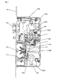
- the first aspect of the present invention relates to a lock (1) having first a lock case (103) with a lock case insert (10301), a bottom (10303) and a ceiling (10305) and a forend associated with the lock case (103) (105). From the lock case (103) out a latch bolt (107) is resiliently biased.
- the lock (1) further comprises a two-piece nut (109) with a cover-nut half (108a) and a bottom nut half (109b) and a spring-loaded, adjustable nut coupling (111).
- a motor-driven adjusting device (113) is provided which has an electric motor (11301) with a motor control (11305).
- the lock (1) comprises an electronic radio module (115) and an energy source (117) for the adjusting device (113) and the radio module (115).
- the lock (1) is particularly characterized in that the motor-operated adjusting device (113) has a bell-shaped actuator (11303) which is in frictional contact with the nut coupling (111) via its end face arranged at right angles to its axis of rotation, wherein the bell-shaped Actuator (11303) has an end face contour (11303a) shaped to hold the nut coupling (111) in at least one coupling position or in at least one disengaged position of the cover side nut half (109a) and the nut half (109b).
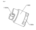
- the bell-shaped actuator (11303) according to the invention, which in a preferred embodiment in FIG. 2 Is shown, is cylindrical with a centrally located pivot axis. It is in its rear, or our part non-positively connected to the axis of the motor-operated adjusting device (113).
- the front or upper Tell remains free.
- an end-face contour (11303a) is formed, which by their non-positive contact with the nut coupling (111) the placement of the nut coupling (111), ie the coupling or decoupling the ceiling-side nut half (109a) and the bottom-side nut half (109b).
- the lock (1) according to the invention has the advantage that for coupling the cover-side nut half (109a) and the bottom nut half (109b) by means of the electric motor-driven nut coupling (111) via the bell-shaped actuator (11303) according to the invention the motor-operated adjusting device (113) has to move only small loads.
- the end face with its end-face contour (11303a) is used on the one hand to set the nut coupling (111) and not, as is common in the prior art, the lateral surface of a conventional adjusting device.
- the travel paths to be managed by the motor-operated adjusting device (113) are short, so that their running times are low.
- the lock case (103) is a standard lock case (mortise lock for rebated doors) according to DIN 18 251, Part 1 (as of September 2014), so that the lock according to the invention can in principle be used in any door with Norming. Inventive alternatives will be described below.
- the latch bolt (107) of the lock (1) according to the invention can be extended by 20 mm from the lock case (103) and preferably provided with molded plastic inserts, which ensure a low-noise and low-wear closing.
- the electronic radio module (115) preferably forms part of a key and access system comprising an antenna and the engine controller (11305) in addition to the radio module (115).
- the frequency used for the radio module (115) is 868 MHz.
- the energy source (117) is embodied according to the invention as a battery or as a rechargeable battery. Preferably, space-saving, thin button cells are used. Since the lock (1) according to the invention is battery-operated, no wiring of the lock (1), or of the lock (1) receiving door is necessary. In principle, each door can therefore be retrofitted with the lock (1) according to the invention.
- the lock (1) according to the invention comprises a capacitor which is designed to bridge the resulting dead time when changing the energy source (117).
- the nut coupling (111) has a projection directed in the direction of the bell-shaped actuator (11303), which engages in the end-face contour (11303a) of the bell-shaped actuator (11303).
- the transition from the coupling-out position into the coupling-in position as an inclined plane and the transition from the coupling-in position into the coupling-out position are carried out as a substantially vertical edge
- the lock (1) comprises at least a first microswitch (119a) which is in frictional contact with the cover-side nut half (109a) and is electrically connected to the motor control (11305) and the radio module (115), and at least one second microswitch (119b) in frictional contact with the bottom nut half (109b) and electrically connected to the engine controller (11305) and the wireless module (115).
- the nut coupling (111) can only be actuated by means of the adjusting device (113) if the first microswitch (119a) and / or second microswitch (119b) detect the rest position of the cover-side nut half (109a) and the nut half (109b).
- the bell-shaped actuator (11303) has a device for interrogating the position.
- this device is designed to query the position as mantelflambalge contour (11303b), which is located on the end face of the contour (11303a) opposite end of the bell-shaped actuator (11303).
- the corresponding microswitch (119a, 119b), the coupled or the disengaged position of the nut coupling (111) is displayed to stop the rotation of the motor-operated adjusting device (113) when the respective position is reached. This prevents the motor-operated adjusting device (113) from “locking up” and thus generating power load peaks.
- the load which the respective microswitch (119a, 119b) applies to the lateral surface contour (11303b) is so small that the significantly reduced energy consumption according to the invention is not noticeably impaired.
- the lock (1) according to the invention further comprises a mechanical lock cylinder (121) for the mechanical actuation of the nut coupling (111).
- the positioning lug of the lock cylinder (121) takes over the function of the motor-operated adjusting device (113) when it is actuated and couples the nut halves (109a, 109b).
- the lock (1) according to the invention further comprises a battery compartment (123) which is received in the lock case (103) and accessible through an opening in the forend (105), the battery compartment (123) being completely removed from the lock case (103). 103) is removable.
- the battery compartment (123) is preferably located at the location of the latch of a conventional lock. To this Welse is a simple change of batteries allows, as by the complete removal of the battery compartment (123) no cables are available. The electrical connection is rather ensured within the lock case (103) by contact connections.
- the battery compartment (123) can also be used to hold batteries.
- high capacity button cells are used in the present invention.
- the battery compartment (123) is spring-mounted in the lock case (103) and to be extendable and removable only by actuating the mechanical lock cylinder (121).
- a pin is attached to the battery compartment (123) according to the invention, which protrudes into a slide for the emergency release described above.
- the lock cylinder (121) By actuating the lock cylinder (121) (as with an emergency release), the pin and thus the battery compartment (123) is released.
- the battery compartment is not unintentionally opened in an emergency release and pushed out by the spring load, An additional closure is provided from the face side.
- the distance measure between 72 mm and 94 mm can be mounted to any desired degree.
- even old doors that have no conventional distance measure can be equipped with the modern lock according to the invention (1) with relatively little effort.
- the distance measure can be mounted on 72 mm, 88 mm or 92 mm. While distance measurements of 72 mm or 92 mm are common in Germany, a distance measurement of 88 mm is frequently used in Austria.
- the cuff (105), shelves (10303) and blankets (10305) can be held in the appropriate dimensions and easily assembled by screw connections. Due to the geometric simplicity of the cuff (105), shelves (10303) and blankets (10305), these can be made with little effort in individual pieces or small series.
- a second aspect of the present invention is an electronic locking system comprising the above-described lock (1) according to the invention, at least one radio lock (3) and at least one mechanical key (5),
- the locking system according to the invention has substantially the same advantages as the lock according to the invention (1). In addition, it is possible to release up to 100 radio keys (3) for a lock (1) according to the invention.
- FIG. 1 gives a schematic overview of the lock 1 according to the invention again, from which all important elements are recognizable.
- the lock 1 according to the invention and the electronic locking system can also be referred to simply as "radio lock".
- the radio lock has an integrated access system due to the electronic radio module 115 (as transmitting and receiving module).
- the lock 1 By means of an authorized remote key 3 (transponder, handheld transmitter), which must be previously released electronically (lock-in) at the lock 1, to a To obtain access authorization, the lock 1 can be controlled in the manner and catfish described below.
- the cover-half nut half 109a and the bottom-half nut half 109b are decoupled from one another.
- the nut half 109a, 109b arranged on a first side (in particular on the inside) of a door can be actuated by a pusher and, by virtue of its rotational movement, pulls the latching rug 107 back to open the door. From the first page, the door can be opened at any time. In particular, a panic function of the door is ensured.
- the nut half 109a, 108b arranged on the second side (in particular on the outside) of the door is idle, so that the actuation of a pusher connected to it does not open the door,
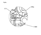
- the spring-mounted, adjustable nut coupling 11 is in the basic position of the lock 1 according to the invention in its rest position in a position in which the cover-side half of the nut 109a and the bottom half of the nut 109b are decoupled from each other (cf. Fig. 3a ).
- the spring bearing causes (supported by gravity) holding the nut coupling 111 in the rest position.
- the spring force is low, so that while the nut coupling 111 is securely held in its rest position, but for the deflection of which no large forces are necessary.
- the cover-side nut half 109a and the bottom nut half 109b must be coupled together, which is achieved by the deflection of the nut coupling 111 in such a way that a latching nose of the nut coupling 111 into corresponding mutually matching recesses of the nut halves 109a, 109b is pushed and so the nut half 109a, 109b coupled together (see. Fig. 4a ).
- the motor-operated adjusting device 113 is set by the electronic radio module 116 in operation, if this receives the release by pressing a remote key 3.
- FIG. 2 It represents an embodiment of the bell-shaped actuator 11303, it sits on the shaft of a motor, which is part of the motor-driven actuator 113.
- a kind of "up-and-down lane" is provided, which in this embodiment has two coupling positions and two coupling positions, such that the bell-shaped actuator 11303 only has to rotate through 90 ° about the coupling position ("Mountain") or the decoupling position ("valley”). This achieves an extremely short motorized tents.
- the nut coupling 111 has a projection which slides on the end-face contour 11303a.
- the previously idle nut half 109a, 109b can be actuated by means of the pusher connected to it and the door can also be opened from the second side.
- the launch position is maintained by default for 5 seconds after the remote key 3 is actuated, then the nut halves 109a, 109b are automatically decoupled.
- the system has the ability to maintain the launch position for a period of time to be determined, i. to unlock the launch position for any period.
- Each nut half 109a, 109b actuates upon reaching their basic position a separate slide, which in turn actuates a respective microswitch 119a, 119b, which thus transmits the information about the basic position to the motor-operated adjusting device 113. Only with this information about the basic position, the motor-driven actuator 113 can be put into operation at all. Thus, blockages and unnecessary power consumption are avoided, for Example because the remote control key 3 is operated while the pusher is already lightly pressed.
- the angle of rotation of the nut halves 109a, 109b is about 30 °, so that the lock 1 according to the invention is compatible, for example, with the panic bars of the applicants.
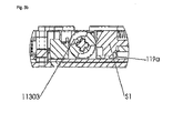
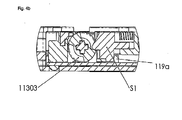
- FIGS. 3b and 4b show a further embodiment of the invention.
- a slider S1 is provided, which is spring-loaded aligned with the fulcrum of the bell-shaped actuator 11303. At its end facing away from the bell-shaped actuator 11303, it is in contact with a microswitch 119a.
- FIG. 3b If the slide S1 through a second lateral surface contour 11303b in the lower region of in FIG. 2 retracted illustrated bell-shaped actuator 11303 and are via the microswitch 119a the feedback that the nut coupling 111 is decoupled.
- the slider S1 is extended and the microswitch 119a gives the feedback that the nut coupling 111 is coupled.
Landscapes
- Engineering & Computer Science (AREA)
- Structural Engineering (AREA)
- Lock And Its Accessories (AREA)
Priority Applications (1)
| Application Number | Priority Date | Filing Date | Title |
|---|---|---|---|
| PL15002717T PL2998487T3 (pl) | 2014-09-22 | 2015-09-21 | Zamek i elektroniczny system zamykania |
Applications Claiming Priority (1)
| Application Number | Priority Date | Filing Date | Title |
|---|---|---|---|
| DE102014113621.7A DE102014113621A1 (de) | 2014-09-22 | 2014-09-22 | Schloss und elektronisches Schließsystem |
Publications (4)
| Publication Number | Publication Date |
|---|---|
| EP2998487A2 true EP2998487A2 (fr) | 2016-03-23 |
| EP2998487A3 EP2998487A3 (fr) | 2016-06-22 |
| EP2998487B1 EP2998487B1 (fr) | 2017-03-29 |
| EP2998487B8 EP2998487B8 (fr) | 2017-07-19 |
Family
ID=54185819
Family Applications (1)
| Application Number | Title | Priority Date | Filing Date |
|---|---|---|---|
| EP15002717.5A Active EP2998487B8 (fr) | 2014-09-22 | 2015-09-21 | Serrure et systeme de fermeture electronique |
Country Status (3)
| Country | Link |
|---|---|
| EP (1) | EP2998487B8 (fr) |
| DE (1) | DE102014113621A1 (fr) |
| PL (1) | PL2998487T3 (fr) |
Cited By (3)
| Publication number | Priority date | Publication date | Assignee | Title |
|---|---|---|---|---|
| WO2021023278A1 (fr) * | 2019-08-06 | 2021-02-11 | 云丁网络技术(北京)有限公司 | Système de protection intelligent |
| EP3593673B1 (fr) * | 2018-07-10 | 2021-12-22 | King Slide Works Co., Ltd. | Système de meuble |
| US12428874B2 (en) | 2021-12-17 | 2025-09-30 | Assa Abloy Americas Residential Inc. | Electronic lock with mortise insert |
Families Citing this family (2)
| Publication number | Priority date | Publication date | Assignee | Title |
|---|---|---|---|---|
| DE102016118119A1 (de) | 2016-09-26 | 2018-03-29 | Assa Abloy (Schweiz) Ag | Modulares Schloss |
| DE102023125116B3 (de) * | 2023-09-18 | 2024-12-19 | Carl Fuhr GmbH & Co. KG. | Schloss, Schließanlage und Verfahren zum Betrieb eines Schlosses oder einer Schließanlage |
Citations (2)
| Publication number | Priority date | Publication date | Assignee | Title |
|---|---|---|---|---|
| DE202010006954U1 (de) | 2010-05-11 | 2010-08-05 | Bks Gmbh | Schließvorrichtung mit motorischer Antriebseinrichtung |
| DE102010046494A1 (de) | 2010-09-24 | 2012-03-29 | Bks Gmbh | Schließeinrichtung und Betriebsverfahren hierfür |
Family Cites Families (10)
| Publication number | Priority date | Publication date | Assignee | Title |
|---|---|---|---|---|
| GB2206638B (en) * | 1987-05-22 | 1991-03-20 | Pickersgill Kaye Ltd | Electromechanical lock |
| US5862692A (en) * | 1996-10-11 | 1999-01-26 | C.L. Industries, Inc. | Safe door lock with servo motor operated cam |
| DE29818458U1 (de) * | 1998-10-15 | 1999-01-07 | HEWI Heinrich Wilke GmbH, 34454 Bad Arolsen | Schaltmechanismus |
| US6094953A (en) * | 1998-11-10 | 2000-08-01 | Mas-Hamilton Group, Inc. | Electrically controlled slidebolt lock |
| AT408468B (de) * | 1999-10-08 | 2001-12-27 | Kaba Gege Gmbh | Schloss |
| AT408119B (de) * | 1999-11-03 | 2001-09-25 | Kaba Gege Gmbh | Geteilter dorn |
| WO2002057575A1 (fr) * | 2001-01-22 | 2002-07-25 | Richard Wendl | Dispositif de fermeture a commande electronique |
| DE202006005337U1 (de) * | 2006-04-03 | 2006-06-08 | Hewi Heinrich Wilke Gmbh | Einsteckschloss |
| DE202011108234U1 (de) * | 2011-11-24 | 2011-12-12 | ASTRA Gesellschaft für Asset Management mbH & Co. KG | Selbstverriegelndes Fallenschloss |
| DE102012010786A1 (de) * | 2012-06-01 | 2013-12-05 | Assa Abloy Sicherheitstechnik Gmbh | Panikschloss mit Selektionseinrichtung im Schlosskasten |
-
2014
- 2014-09-22 DE DE102014113621.7A patent/DE102014113621A1/de not_active Withdrawn
-
2015
- 2015-09-21 EP EP15002717.5A patent/EP2998487B8/fr active Active
- 2015-09-21 PL PL15002717T patent/PL2998487T3/pl unknown
Patent Citations (2)
| Publication number | Priority date | Publication date | Assignee | Title |
|---|---|---|---|---|
| DE202010006954U1 (de) | 2010-05-11 | 2010-08-05 | Bks Gmbh | Schließvorrichtung mit motorischer Antriebseinrichtung |
| DE102010046494A1 (de) | 2010-09-24 | 2012-03-29 | Bks Gmbh | Schließeinrichtung und Betriebsverfahren hierfür |
Cited By (5)
| Publication number | Priority date | Publication date | Assignee | Title |
|---|---|---|---|---|
| EP3593673B1 (fr) * | 2018-07-10 | 2021-12-22 | King Slide Works Co., Ltd. | Système de meuble |
| US11692374B2 (en) | 2018-07-10 | 2023-07-04 | King Slide Works Co., Ltd. | Lock mechanism for objects movable relative to each other |
| WO2021023278A1 (fr) * | 2019-08-06 | 2021-02-11 | 云丁网络技术(北京)有限公司 | Système de protection intelligent |
| US11746564B2 (en) | 2019-08-06 | 2023-09-05 | Yunding Network Technology (Beijing) Co., Ltd. | Systems for smart security |
| US12428874B2 (en) | 2021-12-17 | 2025-09-30 | Assa Abloy Americas Residential Inc. | Electronic lock with mortise insert |
Also Published As
| Publication number | Publication date |
|---|---|
| PL2998487T3 (pl) | 2017-10-31 |
| DE102014113621A1 (de) | 2016-03-24 |
| EP2998487A3 (fr) | 2016-06-22 |
| EP2998487B8 (fr) | 2017-07-19 |
| EP2998487B1 (fr) | 2017-03-29 |
Similar Documents
| Publication | Publication Date | Title |
|---|---|---|
| EP2201535B1 (fr) | Dispositif de verrouillage | |
| EP2998487B1 (fr) | Serrure et systeme de fermeture electronique | |
| DE112007001299B4 (de) | Nockenschloss mit rückziehbarem Dorn | |
| EP1292747B1 (fr) | Serrure a verrouillage automatique et systeme de fermeture comportant une telle serrure | |
| EP2909402B1 (fr) | Système d'actionnement d'une serrure | |
| DE102014112122B4 (de) | Verfahren zum Sperren und Freigeben eines Türblatts und Türanordnung | |
| EP2050902A1 (fr) | Fermeture de meuble mécatronique | |
| DE102016104779A1 (de) | Anti-Panikdruckstange mit Antriebseinrichtung | |
| DE102004046778B4 (de) | Schließzylinder mit erhöhter Eingriffssicherheit | |
| DE102008057034B4 (de) | Vorrichtung zum Öffnen einer Tür | |
| EP2463460B1 (fr) | Verrou de porte électrique doté d'un mécanisme d'arrêt de porte | |
| EP1229192A2 (fr) | Système de verrouillage pour porte | |
| EP1160399B1 (fr) | Serrure commandée électriquement | |
| DE102014104128B4 (de) | Zuhaltung | |
| EP3045623B1 (fr) | Dispositif de sécurisation de porte | |
| EP3516138B1 (fr) | Serrure de porte | |
| EP3126597A1 (fr) | Serrure pour porte ou fenêtre | |
| DE102015000611B4 (de) | Verriegelungsvorrichtung für eine Tür | |
| DE202013005488U1 (de) | Türschloss | |
| DE102015119233B4 (de) | Sicherungsvorrichtung für eine Tür | |
| DE202017107457U1 (de) | Türschloss mit einem elektromotorischen Antrieb und Türschlossanordnung | |
| EP2385193A2 (fr) | Dispositif de fermeture pour une porte | |
| EP3032004B1 (fr) | Système de verrouillage pour une porte ou pour une fenêtre et procédé de fabrication d'un système de verrouillage | |
| DE60201351T2 (de) | Autonome motorantriebseinheit für ein schiebetor | |
| EP3626917A1 (fr) | Poignée de commande pourvue de système de contrôle d'accès |
Legal Events
| Date | Code | Title | Description |
|---|---|---|---|
| PUAI | Public reference made under article 153(3) epc to a published international application that has entered the european phase |
Free format text: ORIGINAL CODE: 0009012 |
|
| AK | Designated contracting states |
Kind code of ref document: A2 Designated state(s): AL AT BE BG CH CY CZ DE DK EE ES FI FR GB GR HR HU IE IS IT LI LT LU LV MC MK MT NL NO PL PT RO RS SE SI SK SM TR |
|
| AX | Request for extension of the european patent |
Extension state: BA ME |
|
| PUAL | Search report despatched |
Free format text: ORIGINAL CODE: 0009013 |
|
| AK | Designated contracting states |
Kind code of ref document: A3 Designated state(s): AL AT BE BG CH CY CZ DE DK EE ES FI FR GB GR HR HU IE IS IT LI LT LU LV MC MK MT NL NO PL PT RO RS SE SI SK SM TR |
|
| AX | Request for extension of the european patent |
Extension state: BA ME |
|
| RIC1 | Information provided on ipc code assigned before grant |
Ipc: E05B 47/06 20060101ALI20160518BHEP Ipc: E05B 63/16 20060101AFI20160518BHEP |
|
| 17P | Request for examination filed |
Effective date: 20160728 |
|
| RBV | Designated contracting states (corrected) |
Designated state(s): AL AT BE BG CH CY CZ DE DK EE ES FI FR GB GR HR HU IE IS IT LI LT LU LV MC MK MT NL NO PL PT RO RS SE SI SK SM TR |
|
| GRAP | Despatch of communication of intention to grant a patent |
Free format text: ORIGINAL CODE: EPIDOSNIGR1 |
|
| INTG | Intention to grant announced |
Effective date: 20161017 |
|
| GRAS | Grant fee paid |
Free format text: ORIGINAL CODE: EPIDOSNIGR3 |
|
| GRAA | (expected) grant |
Free format text: ORIGINAL CODE: 0009210 |
|
| AK | Designated contracting states |
Kind code of ref document: B1 Designated state(s): AL AT BE BG CH CY CZ DE DK EE ES FI FR GB GR HR HU IE IS IT LI LT LU LV MC MK MT NL NO PL PT RO RS SE SI SK SM TR |
|
| REG | Reference to a national code |
Ref country code: GB Ref legal event code: FG4D Free format text: NOT ENGLISH |
|
| REG | Reference to a national code |
Ref country code: CH Ref legal event code: EP |
|
| GRAT | Correction requested after decision to grant or after decision to maintain patent in amended form |
Free format text: ORIGINAL CODE: EPIDOSNCDEC |
|
| REG | Reference to a national code |
Ref country code: AT Ref legal event code: REF Ref document number: 879925 Country of ref document: AT Kind code of ref document: T Effective date: 20170415 |
|
| REG | Reference to a national code |
Ref country code: IE Ref legal event code: FG4D Free format text: LANGUAGE OF EP DOCUMENT: GERMAN |
|
| REG | Reference to a national code |
Ref country code: DE Ref legal event code: R096 Ref document number: 502015000759 Country of ref document: DE |
|
| RAP2 | Party data changed (patent owner data changed or rights of a patent transferred) |
Owner name: SUED-METALL SCHLIESSSYSTEME LEIPZIG GMBH |
|
| RAP4 | Party data changed (patent owner data changed or rights of a patent transferred) |
Owner name: SUED-METALL SCHLIESSSYSTEME LEIPZIG GMBH |
|
| PG25 | Lapsed in a contracting state [announced via postgrant information from national office to epo] |
Ref country code: FI Free format text: LAPSE BECAUSE OF FAILURE TO SUBMIT A TRANSLATION OF THE DESCRIPTION OR TO PAY THE FEE WITHIN THE PRESCRIBED TIME-LIMIT Effective date: 20170329 Ref country code: HR Free format text: LAPSE BECAUSE OF FAILURE TO SUBMIT A TRANSLATION OF THE DESCRIPTION OR TO PAY THE FEE WITHIN THE PRESCRIBED TIME-LIMIT Effective date: 20170329 Ref country code: LT Free format text: LAPSE BECAUSE OF FAILURE TO SUBMIT A TRANSLATION OF THE DESCRIPTION OR TO PAY THE FEE WITHIN THE PRESCRIBED TIME-LIMIT Effective date: 20170329 Ref country code: GR Free format text: LAPSE BECAUSE OF FAILURE TO SUBMIT A TRANSLATION OF THE DESCRIPTION OR TO PAY THE FEE WITHIN THE PRESCRIBED TIME-LIMIT Effective date: 20170630 Ref country code: NO Free format text: LAPSE BECAUSE OF FAILURE TO SUBMIT A TRANSLATION OF THE DESCRIPTION OR TO PAY THE FEE WITHIN THE PRESCRIBED TIME-LIMIT Effective date: 20170629 |
|
| REG | Reference to a national code |
Ref country code: NL Ref legal event code: MP Effective date: 20170329 |
|
| REG | Reference to a national code |
Ref country code: AT Ref legal event code: HC Ref document number: 879925 Country of ref document: AT Kind code of ref document: T Owner name: SUED-METALL SCHLIESSSYSTEME LEIPZIG GMBH, DE Effective date: 20170703 |
|
| PG25 | Lapsed in a contracting state [announced via postgrant information from national office to epo] |
Ref country code: SE Free format text: LAPSE BECAUSE OF FAILURE TO SUBMIT A TRANSLATION OF THE DESCRIPTION OR TO PAY THE FEE WITHIN THE PRESCRIBED TIME-LIMIT Effective date: 20170329 Ref country code: BG Free format text: LAPSE BECAUSE OF FAILURE TO SUBMIT A TRANSLATION OF THE DESCRIPTION OR TO PAY THE FEE WITHIN THE PRESCRIBED TIME-LIMIT Effective date: 20170629 Ref country code: LV Free format text: LAPSE BECAUSE OF FAILURE TO SUBMIT A TRANSLATION OF THE DESCRIPTION OR TO PAY THE FEE WITHIN THE PRESCRIBED TIME-LIMIT Effective date: 20170329 Ref country code: RS Free format text: LAPSE BECAUSE OF FAILURE TO SUBMIT A TRANSLATION OF THE DESCRIPTION OR TO PAY THE FEE WITHIN THE PRESCRIBED TIME-LIMIT Effective date: 20170329 |
|
| REG | Reference to a national code |
Ref country code: FR Ref legal event code: PLFP Year of fee payment: 3 |
|
| PG25 | Lapsed in a contracting state [announced via postgrant information from national office to epo] |
Ref country code: NL Free format text: LAPSE BECAUSE OF FAILURE TO SUBMIT A TRANSLATION OF THE DESCRIPTION OR TO PAY THE FEE WITHIN THE PRESCRIBED TIME-LIMIT Effective date: 20170329 |
|
| PG25 | Lapsed in a contracting state [announced via postgrant information from national office to epo] |
Ref country code: SK Free format text: LAPSE BECAUSE OF FAILURE TO SUBMIT A TRANSLATION OF THE DESCRIPTION OR TO PAY THE FEE WITHIN THE PRESCRIBED TIME-LIMIT Effective date: 20170329 Ref country code: EE Free format text: LAPSE BECAUSE OF FAILURE TO SUBMIT A TRANSLATION OF THE DESCRIPTION OR TO PAY THE FEE WITHIN THE PRESCRIBED TIME-LIMIT Effective date: 20170329 Ref country code: ES Free format text: LAPSE BECAUSE OF FAILURE TO SUBMIT A TRANSLATION OF THE DESCRIPTION OR TO PAY THE FEE WITHIN THE PRESCRIBED TIME-LIMIT Effective date: 20170329 Ref country code: RO Free format text: LAPSE BECAUSE OF FAILURE TO SUBMIT A TRANSLATION OF THE DESCRIPTION OR TO PAY THE FEE WITHIN THE PRESCRIBED TIME-LIMIT Effective date: 20170329 Ref country code: CZ Free format text: LAPSE BECAUSE OF FAILURE TO SUBMIT A TRANSLATION OF THE DESCRIPTION OR TO PAY THE FEE WITHIN THE PRESCRIBED TIME-LIMIT Effective date: 20170329 Ref country code: IT Free format text: LAPSE BECAUSE OF FAILURE TO SUBMIT A TRANSLATION OF THE DESCRIPTION OR TO PAY THE FEE WITHIN THE PRESCRIBED TIME-LIMIT Effective date: 20170329 |
|
| REG | Reference to a national code |
Ref country code: NL Ref legal event code: NE Effective date: 20170906 |
|
| PG25 | Lapsed in a contracting state [announced via postgrant information from national office to epo] |
Ref country code: IS Free format text: LAPSE BECAUSE OF FAILURE TO SUBMIT A TRANSLATION OF THE DESCRIPTION OR TO PAY THE FEE WITHIN THE PRESCRIBED TIME-LIMIT Effective date: 20170729 Ref country code: SM Free format text: LAPSE BECAUSE OF FAILURE TO SUBMIT A TRANSLATION OF THE DESCRIPTION OR TO PAY THE FEE WITHIN THE PRESCRIBED TIME-LIMIT Effective date: 20170329 |
|
| REG | Reference to a national code |
Ref country code: DE Ref legal event code: R097 Ref document number: 502015000759 Country of ref document: DE |
|
| PG25 | Lapsed in a contracting state [announced via postgrant information from national office to epo] |
Ref country code: DK Free format text: LAPSE BECAUSE OF FAILURE TO SUBMIT A TRANSLATION OF THE DESCRIPTION OR TO PAY THE FEE WITHIN THE PRESCRIBED TIME-LIMIT Effective date: 20170329 |
|
| PLBE | No opposition filed within time limit |
Free format text: ORIGINAL CODE: 0009261 |
|
| STAA | Information on the status of an ep patent application or granted ep patent |
Free format text: STATUS: NO OPPOSITION FILED WITHIN TIME LIMIT |
|
| 26N | No opposition filed |
Effective date: 20180103 |
|
| PG25 | Lapsed in a contracting state [announced via postgrant information from national office to epo] |
Ref country code: SI Free format text: LAPSE BECAUSE OF FAILURE TO SUBMIT A TRANSLATION OF THE DESCRIPTION OR TO PAY THE FEE WITHIN THE PRESCRIBED TIME-LIMIT Effective date: 20170329 Ref country code: MC Free format text: LAPSE BECAUSE OF FAILURE TO SUBMIT A TRANSLATION OF THE DESCRIPTION OR TO PAY THE FEE WITHIN THE PRESCRIBED TIME-LIMIT Effective date: 20170329 |
|
| REG | Reference to a national code |
Ref country code: IE Ref legal event code: MM4A |
|
| REG | Reference to a national code |
Ref country code: BE Ref legal event code: MM Effective date: 20170930 |
|
| PG25 | Lapsed in a contracting state [announced via postgrant information from national office to epo] |
Ref country code: LU Free format text: LAPSE BECAUSE OF NON-PAYMENT OF DUE FEES Effective date: 20170921 |
|
| PG25 | Lapsed in a contracting state [announced via postgrant information from national office to epo] |
Ref country code: IE Free format text: LAPSE BECAUSE OF NON-PAYMENT OF DUE FEES Effective date: 20170921 |
|
| PG25 | Lapsed in a contracting state [announced via postgrant information from national office to epo] |
Ref country code: BE Free format text: LAPSE BECAUSE OF NON-PAYMENT OF DUE FEES Effective date: 20170930 |
|
| REG | Reference to a national code |
Ref country code: FR Ref legal event code: PLFP Year of fee payment: 4 |
|
| PG25 | Lapsed in a contracting state [announced via postgrant information from national office to epo] |
Ref country code: MT Free format text: LAPSE BECAUSE OF FAILURE TO SUBMIT A TRANSLATION OF THE DESCRIPTION OR TO PAY THE FEE WITHIN THE PRESCRIBED TIME-LIMIT Effective date: 20170329 |
|
| PG25 | Lapsed in a contracting state [announced via postgrant information from national office to epo] |
Ref country code: HU Free format text: LAPSE BECAUSE OF FAILURE TO SUBMIT A TRANSLATION OF THE DESCRIPTION OR TO PAY THE FEE WITHIN THE PRESCRIBED TIME-LIMIT; INVALID AB INITIO Effective date: 20150921 |
|
| PG25 | Lapsed in a contracting state [announced via postgrant information from national office to epo] |
Ref country code: CY Free format text: LAPSE BECAUSE OF FAILURE TO SUBMIT A TRANSLATION OF THE DESCRIPTION OR TO PAY THE FEE WITHIN THE PRESCRIBED TIME-LIMIT Effective date: 20170329 |
|
| PG25 | Lapsed in a contracting state [announced via postgrant information from national office to epo] |
Ref country code: MK Free format text: LAPSE BECAUSE OF FAILURE TO SUBMIT A TRANSLATION OF THE DESCRIPTION OR TO PAY THE FEE WITHIN THE PRESCRIBED TIME-LIMIT Effective date: 20170329 |
|
| PG25 | Lapsed in a contracting state [announced via postgrant information from national office to epo] |
Ref country code: TR Free format text: LAPSE BECAUSE OF FAILURE TO SUBMIT A TRANSLATION OF THE DESCRIPTION OR TO PAY THE FEE WITHIN THE PRESCRIBED TIME-LIMIT Effective date: 20170329 |
|
| PG25 | Lapsed in a contracting state [announced via postgrant information from national office to epo] |
Ref country code: PT Free format text: LAPSE BECAUSE OF FAILURE TO SUBMIT A TRANSLATION OF THE DESCRIPTION OR TO PAY THE FEE WITHIN THE PRESCRIBED TIME-LIMIT Effective date: 20170329 |
|
| PG25 | Lapsed in a contracting state [announced via postgrant information from national office to epo] |
Ref country code: AL Free format text: LAPSE BECAUSE OF FAILURE TO SUBMIT A TRANSLATION OF THE DESCRIPTION OR TO PAY THE FEE WITHIN THE PRESCRIBED TIME-LIMIT Effective date: 20170329 |
|
| REG | Reference to a national code |
Ref country code: CH Ref legal event code: U11 Free format text: ST27 STATUS EVENT CODE: U-0-0-U10-U11 (AS PROVIDED BY THE NATIONAL OFFICE) Effective date: 20251001 |
|
| PGFP | Annual fee paid to national office [announced via postgrant information from national office to epo] |
Ref country code: DE Payment date: 20250919 Year of fee payment: 11 |
|
| PGFP | Annual fee paid to national office [announced via postgrant information from national office to epo] |
Ref country code: PL Payment date: 20250905 Year of fee payment: 11 |
|
| PGFP | Annual fee paid to national office [announced via postgrant information from national office to epo] |
Ref country code: GB Payment date: 20250923 Year of fee payment: 11 |
|
| PGFP | Annual fee paid to national office [announced via postgrant information from national office to epo] |
Ref country code: FR Payment date: 20250922 Year of fee payment: 11 Ref country code: AT Payment date: 20250918 Year of fee payment: 11 |
|
| PGFP | Annual fee paid to national office [announced via postgrant information from national office to epo] |
Ref country code: CH Payment date: 20251001 Year of fee payment: 11 |