EP2999320A1 - Dispositif de transfert de chaleur - Google Patents
Dispositif de transfert de chaleur Download PDFInfo
- Publication number
- EP2999320A1 EP2999320A1 EP14185527.0A EP14185527A EP2999320A1 EP 2999320 A1 EP2999320 A1 EP 2999320A1 EP 14185527 A EP14185527 A EP 14185527A EP 2999320 A1 EP2999320 A1 EP 2999320A1
- Authority
- EP
- European Patent Office
- Prior art keywords
- heat
- wedges
- wedge
- conducting bodies
- conducting body
- Prior art date
- Legal status (The legal status is an assumption and is not a legal conclusion. Google has not performed a legal analysis and makes no representation as to the accuracy of the status listed.)
- Withdrawn
Links
Images

Classifications
-
- F—MECHANICAL ENGINEERING; LIGHTING; HEATING; WEAPONS; BLASTING
- F28—HEAT EXCHANGE IN GENERAL
- F28F—DETAILS OF HEAT-EXCHANGE AND HEAT-TRANSFER APPARATUS, OF GENERAL APPLICATION
- F28F5/00—Elements specially adapted for movement
-
- H—ELECTRICITY
- H05—ELECTRIC TECHNIQUES NOT OTHERWISE PROVIDED FOR
- H05K—PRINTED CIRCUITS; CASINGS OR CONSTRUCTIONAL DETAILS OF ELECTRIC APPARATUS; MANUFACTURE OF ASSEMBLAGES OF ELECTRICAL COMPONENTS
- H05K7/00—Constructional details common to different types of electric apparatus
- H05K7/20—Modifications to facilitate cooling, ventilating, or heating
- H05K7/2039—Modifications to facilitate cooling, ventilating, or heating characterised by the heat transfer by conduction from the heat generating element to a dissipating body
- H05K7/20436—Inner thermal coupling elements in heat dissipating housings, e.g. protrusions or depressions integrally formed in the housing
- H05K7/20445—Inner thermal coupling elements in heat dissipating housings, e.g. protrusions or depressions integrally formed in the housing the coupling element being an additional piece, e.g. thermal standoff
-
- H—ELECTRICITY
- H10—SEMICONDUCTOR DEVICES; ELECTRIC SOLID-STATE DEVICES NOT OTHERWISE PROVIDED FOR
- H10W—GENERIC PACKAGES, INTERCONNECTIONS, CONNECTORS OR OTHER CONSTRUCTIONAL DETAILS OF DEVICES COVERED BY CLASS H10
- H10W40/00—Arrangements for thermal protection or thermal control
- H10W40/70—Fillings or auxiliary members in containers or in encapsulations for thermal protection or control
- H10W40/77—Auxiliary members characterised by their shape
- H10W40/774—Pistons, e.g. spring-loaded members
Definitions
- the invention relates to a device for transferring heat between a heat source and a heat sink by heat conduction.
- a heat exchanger is used in particular in industrial electronics to derive the power loss of electronic components.
- Modern multi-core processors with a high clock rate have such a high thermal power loss that they require targeted cooling for safe operation. This is usually done by means of a heat sink, which is placed on the planar surface of the processor and a Having a plurality of cooling fins, so that the waste heat from a large area can be dissipated by convection to the surrounding air.
- the electronic components of a device must be enclosed in a housing to protect it against dust, moisture, and radiated emissions.
- the housing may have air inlet and outlet openings and / or be equipped with an electric fan, which blows cooling air through the housing.
- a completely enclosed housing is required to meet increased requirements for dust and moisture protection.
- Enclosures for electronic devices, especially industrial computers, with higher IP protection class are sealed all around, so that no cooling air can be passed through the housing. Instead, such closed housing on their outsides large heat sink, which are designed for example as extruded profile body. It raises the problem here, the electronic components inside the housing, so in particular the processor or processors to thermally connect to the heat sinks on the outside of the housing, so that the heat loss transported by conduction to the heat sinks and there by convection and / or heat radiation can be delivered to the environment.
- US 2007/0030656 A1 describes a variable height heat transfer device.
- the device comprises two intermeshing bodies, of which the first body has contact with a heat-emitting component and the second body is displaceable in the vertical direction with respect to the first body. Between the two bodies sits a spring, which presses the upper body up against the inside of a lid of a housing. The spring pressure thus ensures that the upper body always has contact with the housing cover, even if its relative height to the housing bottom varies, for example because of manufacturing tolerances.
- the lower heat conducting body is formed in the manner of a piston and the upper heat conducting body in the manner of a cylinder which can slide up and down in the piston.
- the object is to provide an improved heat conducting device, which can compensate for a relatively large tolerance range and is still characterized by maximum thermal conductivity.
- the heat exchanger according to the invention has two massive heat conducting body, which are arranged vertically one above the other at a variable distance. Between the two bodies sitting at least one spreading element comprising two horizontally movable wedges. The wedge points point in opposite directions. Between the wedges at least one spring is arranged, which presses apart the wedges along a horizontal axis.
- the sauceleit emotions have on their sides facing each other corresponding sliding surfaces, which are arranged in pairs. The wedge surfaces slide on the sliding surfaces of the heat conducting body such that a movement of the wedges in the horizontal direction is converted into a vertical movement of the heat conducting body. The wedge surfaces always run parallel to the sliding surfaces.
- the force of the spring which is compensated by pressure on the upper heat-conducting body, ensures that the wedge surfaces always rest without any appreciable gap on the sliding surfaces of the heat-conducting body. Nevertheless, the vertical distance between the two soupleitoasan is variable, so that the height of the heat transfer device automatically adapts to the structural conditions, for example, to compensate for different levels of processors or manufacturing tolerances of the housing.
- the spring also ensures that the wedges are pressed onto the sliding surfaces of the rondleitschreib, so that a good heat transfer between wedges and perennialleit stressesn is guaranteed. Heat-conducting bodies and wedges complement each other to form an almost completely solid body with minimal thermal resistance between the outer contact surfaces.
- the wedges have a cross section in which the wedge surfaces lie on the legs of an isosceles triangle.
- the shape of the wedges is thus symmetrical with respect to a horizontal axis which is transverse to the direction of movement of the heat conducting body. This results in a double stroke in the vertical direction than would be the case with the use of wedges with only one inclined wedge surface.
- other cross-sectional shapes for the wedges are conceivable, for example, the shape of a transverse rectangular triangle, in which then one, preferably the upper wedge surface obliquely and the other wedge surface is parallel to the horizontal.
- the wedge surfaces In order to achieve a long stroke in the vertical direction on a short horizontal path, it is expedient to arrange the wedge surfaces at an obtuse angle. This is possible here because the weights to be moved and thus the frictional forces between wedge surfaces and sliding surfaces are relatively small. However, should the device have larger dimensions, placement of the wedge surfaces at an angle of less than 90 degrees could be advantageous.
- the arranged between the wedges spring is preferably formed as a helical spring, wherein the spring axis lies in a horizontal plane through the wedge tip.
- two or more springs will be arranged side by side in parallel to prevent tilting of the wedges. If the wedges and the wedge surfaces are arranged symmetrically on both sides of the same horizontal plane, this results in an overall symmetrical arrangement which offers advantages with regard to kinematics, in particular to an automatic centering of the wedges in the bearings jointly formed by a respective sliding surface of the two heat conducting bodies. Tilting of the heat-conducting body is thereby prevented.
- the heat-conducting body can be connected to each other by a guide so that they are substantially only movable in the vertical direction against each other, but can not escape laterally.
- This vertical guide can advantageously have a stop which limits the maximum mutual displacement of the heat conducting body. Even with completely relaxed Spring, so the maximum possible distance of the heat-conducting body from each other, thereby a falling apart of the device is prevented, the assembly is simplified.
- the two cherriesleitaires each have two pairs of V-shaped sliding surfaces on which slide the wedges each one of the two expansion elements.
- the arrangement of two equal expansion elements is advantageous because it automatically ensures a constant tension of the two heat-conducting body to each other.
- the heat-conducting body are preferably produced in one piece as an extruded profile.
- the material is preferably a metal with very good thermal conductivity, in particular aluminum or copper.
- the wedges can be made in one piece as an extruded profile of the same material.
- the two heat conducting body are made of the same extruded profile is particularly advantageous.
- the upper heat-conducting body then differs from the lower heat-conducting body only in that it is arranged rotated by 180 degrees. Since the wedges are the same design, the entire device can be composed essentially of only three different parts, namely two identical heat conducting bodies, at least two identical wedges and a spring or more identical springs.
- the vertical guide for the heat conducting together with stop can be formed by integrally formed on the heat conducting body webs, so that no further parts must be made for this purpose.
- processors of computers are usually installed in a housing so that their upper side, from which the heat has to be dissipated, is actually oriented approximately horizontally in the room, and that insofar the two heat-conducting bodies of the device according to the invention are also arranged approximately vertically above one another , Protection is claimed at least for heat transfer devices in which, for example, the heat conduction along a horizontal axis face each other and, accordingly, the wedges of the at least one expansion element along a vertical axis - and thus perpendicular or transversely to the direction of movement of the heat conducting body - are movable, so that a Movement of the wedges in the vertical direction is converted into a horizontal movement of the heat conducting body.
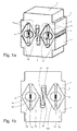
- FIG. 1a shows a heat exchanger with a first heat-conducting body 1 and a second, spaced vertically above the heat-conducting body 2.
- the two heat-conducting body 1, 2 have substantially the shape of a rectangular parallelepiped, the narrow end faces have a gradation 3, so that the width of the heat-conducting body 1, 2 is slightly reduced in the region of their opposite ends.
- the underside of the lower heat conducting body 1 forms a first planar contact surface 4, the upper side of the upper heat conducting body 2 a second planar contact surface 5.
- These contact surfaces 4, 5 are used to produce a planar contact to a (not shown) component from which heat is to be dissipated , or to a device, such as a housing cover that can absorb heat.
- the thermal gradient along the vertical axis of the heat exchanger causes a heat flow between the two contact surfaces 4, 5 from bottom to top or in the opposite direction, ie from top to bottom.
- each of the contact surfaces 4, 5 opposite sides of the heat conducting body 1, 2 are each two pairs of sliding surfaces 6a, 6b and 7a, 7b formed.
- the sliding surfaces 6a, 6b of the lower bathleit stresses are arranged in the form of a V; the sliding surfaces 7a, 7b of the upper réelleleit stressess are also arranged V-shaped, the V however is upside down.
- the sliding surfaces 6a, 6b, 7a, 7b are arranged on the legs of a total of four isosceles triangles, wherein the Points of two triangles point in opposite directions, so that a total of two diamonds are formed.
- FIGS. 1a, 1b left spreader 8 comprises two wedges 10a, 10b with wedge tips facing away from each other and a spring 11 arranged between the wedges.
- the second spreader element 9 of the same design (in FIG. 1b right) also comprises two wedges 12a, 12b with diverging tips and an intermediate spring 13.
- the springs 11, 13 designed as helical springs push apart the associated wedges 10a, 10 or 12a, 12b in the horizontal direction.
- the wedge surfaces 14 slide on the respectively associated sliding surfaces 6a, 6b of the lower heat conducting body 1 or on the sliding surfaces 7a, 7b of the upper heat conducting body 2.
- the wedge surfaces 14 and the associated sliding surfaces 6a, 6b and 7a, 7b run parallel, the means that they lie on the entire surface and almost no gap on each other.
- the wedges have 10a, 10b, 12a, 12b at their opposite the wedge tips backsides semi-circular grooves 15 in which strips 16 sit, whose cross section is also semicircular.
- the springs 11, 13 are supported against the flat tops of the strips 16.
- the strips 16 can twist slightly in the grooves 15 and thus compensate for a not exactly horizontal orientation of the heat-conducting body 1 and 2 against each other.
- the heat conducting body 1, 2 have at their mutually facing inner sides mirror-image shaped, but laterally offset slightly arranged guide webs 17, 18, which form a vertical guide for the heat conducting body 1, 2. At their free ends, the guide webs 17, 18 are angled outwards, whereby horizontal stops 19 and 20 are formed. These stops 19, 20 limit the way that the upper heat conducting body 2 can move away from the lower heat conducting body 1 in the vertical direction, wherein the guide webs 17, 18 move parallel and thus pretend a purely vertical displacement of the heat conducting body 1, 2 against each other.
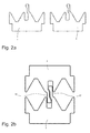
- FIG. 2a the two heat-conducting bodies 1, 2 are shown separately. They are manufactured in one piece from the same extruded profile.
- FIG. 2a are the two heat-conducting body 1, 2 arranged side by side, whereas FIG. 2b show the two heat-conducting body 1 and 2 pushed together.
- the upper heat conducting body 2 was rotated by 180 degrees on the lower heat conducting body 1 is pushed.
- FIG. 3 illustrates the function of the heat exchanger described above.
- the two heat-conducting bodies 1, 2 almost abut each other, so have a minimum distance, so that the entire device has minimal height.
- the two heat-conducting bodies 1, 2 have a maximum distance from each other in the vertical direction, so that the device has maximum height.
- the difference between minimum and maximum height gives the variable distance between two components (not shown) that can be connected by the device for the purpose of transferring heat.
- the springs 11, 13 ensure that a movement of the wedges 10a, 10b and 12a, 12b in the horizontal direction is converted into a vertical movement of the heat conducting body 1, 2 in the vertical direction against each other.
- the springs 11, 13 are maximally compressed, while they are almost completely relaxed in the left figure.
- the stops 19, 20 on the guide webs 17, 18 limit the vertical movement of the upper heat conducting body 2 relative to the lower heat conducting body. 1
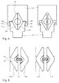
- FIG. 4 show a second alternative embodiment of the heat exchanger.
- This device also comprises a lower heat-conducting body 1 and an upper heat-conducting body 2, which is arranged vertically above the first heat-conducting body 1 at a variable distance.
- the lower heat conducting body 1 is slightly narrower than the upper heat conducting body 2.
- a single expansion element 108 which is arranged between the two planteleit stresses 101, 102 and two horizontally movable wedges 110a, 110b, the wedge tips facing in opposite directions.
- FIG. 4 In the embodiment according to FIG. 4 are on the upper heat conducting body 2 right and left guide webs 118a, 118b integrally formed, which surround the lower heat-conducting body 1 laterally a piece.
- the guide webs 118a, 118b have at their free ends inwardly directed bends, which form stops 119a, 119b. These interact with counter-stops 120a, 120b on the lower heat-conducting body 101.
- the expansion element 108 is in principle the same design as the two expansion elements 8, 9 of the first embodiment of the heat exchanger (see. FIG. 1a, 1b ).
- the expansion element 108 comprises, in addition to the wedges 110a, 110b, a spring (not illustrated here) which presses the wedges 110a, 110b apart in the horizontal direction.
- FIG. 5 show a modified version of the spreading elements 8, 9 and 108.
- the wedges 210a, 210b have grooves here, which do not have a semicircular cross-section, but have a cross section in the form of an isosceles triangle with rounded tip.
- the ridges 216 seated in the grooves 215 also have a cross-section in the shape of an isosceles triangle, with the angle subtended by the legs of this triangle being slightly smaller than the corresponding angle of the grooves 215.
- the strips 216 can tilt by a corresponding angle. Thereby, a height offset between the left wedge 210a and the right wedge 210b can be compensated.
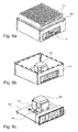
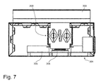
- FIGS. 6a, 6b and 6c illustrate the use of a heat transfer device 300 of the type previously described.
- FIG. 6a shows a closed housing 301 for installation of electronic components, in particular a Mini-ITX single board computer.
- the top of the cover 302 of the housing 301 is almost completely occupied by a heat sink 303, which has a plurality of cooling fins and thus has a large cooling surface.
- FIG. 6b the heat sink 303 is removed, so that the view into the interior of the housing 301 is free.
- FIG. 6c In addition, the side walls 304 are omitted, so that the motherboard 305 can be seen.
- a processor 306 the heat loss has to be dissipated.
- the heat transfer device 300 is mounted on the flat top of the processor 306.
- the lower heat-conducting body of the device 300 is covered by a mounting adapter 307. The movement of the upper heat-conducting body with respect to the lower heat-conducting body, which is firmly connected to the processor 306, is not obstructed by the mounting adapter 307.
Landscapes
- Engineering & Computer Science (AREA)
- Physics & Mathematics (AREA)
- Thermal Sciences (AREA)
- Microelectronics & Electronic Packaging (AREA)
- Mechanical Engineering (AREA)
- General Engineering & Computer Science (AREA)
- Cooling Or The Like Of Electrical Apparatus (AREA)
Priority Applications (4)
| Application Number | Priority Date | Filing Date | Title |
|---|---|---|---|
| EP14185527.0A EP2999320A1 (fr) | 2014-09-19 | 2014-09-19 | Dispositif de transfert de chaleur |
| EP15158736.7A EP2999322B1 (fr) | 2014-09-19 | 2015-03-12 | Dispositif de transfert de chaleur |
| US14/857,127 US9863717B2 (en) | 2014-09-19 | 2015-09-17 | Heat transferring device |
| CN201510596712.9A CN105451514B (zh) | 2014-09-19 | 2015-09-18 | 热量传递设备 |
Applications Claiming Priority (1)
| Application Number | Priority Date | Filing Date | Title |
|---|---|---|---|
| EP14185527.0A EP2999320A1 (fr) | 2014-09-19 | 2014-09-19 | Dispositif de transfert de chaleur |
Publications (1)
| Publication Number | Publication Date |
|---|---|
| EP2999320A1 true EP2999320A1 (fr) | 2016-03-23 |
Family
ID=51584990
Family Applications (2)
| Application Number | Title | Priority Date | Filing Date |
|---|---|---|---|
| EP14185527.0A Withdrawn EP2999320A1 (fr) | 2014-09-19 | 2014-09-19 | Dispositif de transfert de chaleur |
| EP15158736.7A Active EP2999322B1 (fr) | 2014-09-19 | 2015-03-12 | Dispositif de transfert de chaleur |
Family Applications After (1)
| Application Number | Title | Priority Date | Filing Date |
|---|---|---|---|
| EP15158736.7A Active EP2999322B1 (fr) | 2014-09-19 | 2015-03-12 | Dispositif de transfert de chaleur |
Country Status (3)
| Country | Link |
|---|---|
| US (1) | US9863717B2 (fr) |
| EP (2) | EP2999320A1 (fr) |
| CN (1) | CN105451514B (fr) |
Cited By (3)
| Publication number | Priority date | Publication date | Assignee | Title |
|---|---|---|---|---|
| US20170363371A1 (en) * | 2016-06-15 | 2017-12-21 | Mellanox Technologies Ltd. | Self-adjusting cooling module |
| CN111442683A (zh) * | 2020-04-15 | 2020-07-24 | 苏州众志新环冷却设备有限公司 | 一种具有降低气流涡流结构的空冷器风室 |
| US12360323B2 (en) | 2022-10-18 | 2025-07-15 | Mellanox Technologies, Ltd | Mechanical thermal interface for improved heat dissipation in network transceivers |
Families Citing this family (6)
| Publication number | Priority date | Publication date | Assignee | Title |
|---|---|---|---|---|
| CN107087377B (zh) * | 2017-04-28 | 2019-04-26 | 华为技术有限公司 | 散热装置、散热器、电子设备及散热控制的方法 |
| CN108415525B (zh) * | 2018-03-23 | 2019-12-31 | 温岭市志创网络科技有限公司 | 改良结构的计算机机壳 |
| CN115692975B (zh) * | 2021-07-30 | 2025-03-07 | 比亚迪股份有限公司 | 散热装置和电池包 |
| CN116193646B (zh) * | 2021-11-26 | 2025-08-26 | 广州联动万物科技有限公司 | 一种发热模块 |
| TWI824910B (zh) * | 2023-01-03 | 2023-12-01 | 凌華科技股份有限公司 | 應用於電子裝置之彈性導熱構件 |
| US12328846B2 (en) * | 2023-02-24 | 2025-06-10 | Adlink Technology Inc. | Elastic heat conduction mechanism for electronic devices |
Citations (4)
| Publication number | Priority date | Publication date | Assignee | Title |
|---|---|---|---|---|
| US20070019384A1 (en) * | 2005-07-19 | 2007-01-25 | Bae Systems Information | Cold plate cooling apparatus for a rack mounted electronic module |
| US20070030656A1 (en) | 2005-08-08 | 2007-02-08 | Verifone Holdings, Inc. | Thermal transfer device |
| US20090229808A1 (en) * | 2008-03-17 | 2009-09-17 | Chung-Jun Chu | Heat-conducting assembly |
| WO2013135595A1 (fr) * | 2012-03-15 | 2013-09-19 | Ecrin Systems | Calculateur et radiateur pour ce calculateur |
Family Cites Families (9)
| Publication number | Priority date | Publication date | Assignee | Title |
|---|---|---|---|---|
| JPH063831B2 (ja) * | 1987-04-08 | 1994-01-12 | 株式会社日立製作所 | 冷却装置及びそれを用いた半導体装置 |
| EP0354722A3 (fr) * | 1988-08-08 | 1991-04-03 | Hitachi, Ltd. | Système de transport de chaleur, en particulier pour refroidir des dispositifs semi-conducteurs |
| US5184281A (en) * | 1992-03-03 | 1993-02-02 | Digital Equipment Corporation | Heat dissipation apparatus |
| DE69401040T2 (de) * | 1993-07-12 | 1997-06-05 | Nippon Electric Co | Gehäusestruktur für Mikrowellenschaltung |
| US6985359B2 (en) * | 2003-04-21 | 2006-01-10 | Hewlett-Packard Development Company, L.P. | Variable-wedge thermal-interface device |
| US7120023B2 (en) * | 2003-08-25 | 2006-10-10 | Hewlett-Packard Development Company, L.P. | Method of assembly of a wedge thermal interface to allow expansion after assembly |
| CN101193536A (zh) * | 2006-11-29 | 2008-06-04 | 英业达股份有限公司 | 散热器结构及其组装治具 |
| CN102131371B (zh) * | 2010-11-11 | 2014-03-26 | 华为技术有限公司 | 一种导热装置及其应用的电子装置 |
| CN103620335B (zh) * | 2011-05-31 | 2016-01-13 | 阿威德热合金有限公司 | 使散热器可定位的散热器支座 |
-
2014
- 2014-09-19 EP EP14185527.0A patent/EP2999320A1/fr not_active Withdrawn
-
2015
- 2015-03-12 EP EP15158736.7A patent/EP2999322B1/fr active Active
- 2015-09-17 US US14/857,127 patent/US9863717B2/en active Active
- 2015-09-18 CN CN201510596712.9A patent/CN105451514B/zh not_active Expired - Fee Related
Patent Citations (4)
| Publication number | Priority date | Publication date | Assignee | Title |
|---|---|---|---|---|
| US20070019384A1 (en) * | 2005-07-19 | 2007-01-25 | Bae Systems Information | Cold plate cooling apparatus for a rack mounted electronic module |
| US20070030656A1 (en) | 2005-08-08 | 2007-02-08 | Verifone Holdings, Inc. | Thermal transfer device |
| US20090229808A1 (en) * | 2008-03-17 | 2009-09-17 | Chung-Jun Chu | Heat-conducting assembly |
| WO2013135595A1 (fr) * | 2012-03-15 | 2013-09-19 | Ecrin Systems | Calculateur et radiateur pour ce calculateur |
Cited By (4)
| Publication number | Priority date | Publication date | Assignee | Title |
|---|---|---|---|---|
| US20170363371A1 (en) * | 2016-06-15 | 2017-12-21 | Mellanox Technologies Ltd. | Self-adjusting cooling module |
| US10054375B2 (en) * | 2016-06-15 | 2018-08-21 | Mellanox Technologies, Ltd. | Self-adjusting cooling module |
| CN111442683A (zh) * | 2020-04-15 | 2020-07-24 | 苏州众志新环冷却设备有限公司 | 一种具有降低气流涡流结构的空冷器风室 |
| US12360323B2 (en) | 2022-10-18 | 2025-07-15 | Mellanox Technologies, Ltd | Mechanical thermal interface for improved heat dissipation in network transceivers |
Also Published As
| Publication number | Publication date |
|---|---|
| CN105451514B (zh) | 2018-05-08 |
| EP2999322A1 (fr) | 2016-03-23 |
| US20160084590A1 (en) | 2016-03-24 |
| US9863717B2 (en) | 2018-01-09 |
| EP2999322B1 (fr) | 2016-11-23 |
| CN105451514A (zh) | 2016-03-30 |
Similar Documents
| Publication | Publication Date | Title |
|---|---|---|
| EP2999322B1 (fr) | Dispositif de transfert de chaleur | |
| DE102017129357B4 (de) | Kühlkörper | |
| DE102013015179B4 (de) | Wärmetauscheranordnung und Herstellungsverfahren | |
| DE112017005498B4 (de) | Halbleiterbauelement und Verfahren zur Herstellung desselben | |
| DE112011101941B4 (de) | Verfahren zum Aufbauen eines Wärmetauschers sowie Wärmetauschervorrichtung | |
| DE112022004158T5 (de) | Halbleitervorrichtung | |
| DE102011079508B4 (de) | Kühlstruktur für ein Halbleiterelement | |
| EP4090145B1 (fr) | Dispositif de refroidissement permettant d'éliminer la chaleur | |
| DE102007003821A1 (de) | Transistorklemmvorrichtung | |
| DE20304781U1 (de) | CPU Kühlbasis | |
| DE202014104475U1 (de) | Vorrichtung zur Übertragung von Wärme | |
| DE102018120657A1 (de) | Kühlstruktur für einen robotermotor | |
| EP3230673B1 (fr) | Élément de compensation par transfert de chaleur et véhicule à propulsion électrique pourvu d'un tel élément de compensation | |
| AT520072B1 (de) | Kühlkörper und Fahrzeugscheinwerfer | |
| EP3223998B1 (fr) | Dispositif pour l'usinage d'une pièce plane | |
| DE102017216598A1 (de) | Kühlkörper und Verfahren zur Herstellung eines Kühlkörpers | |
| EP3468845A1 (fr) | Dispositif d'actionnement électrohydraulique doté de modules de refroidissement | |
| WO2024056772A1 (fr) | Échangeur de chaleur pour le refroidissement de composants | |
| AT526741B1 (de) | Wärmestrahler | |
| EP3113220B1 (fr) | Dissipateur thermique | |
| DE3219571A1 (de) | Gehaeuse fuer elektronische schaltungen | |
| DE102005035387B4 (de) | Kühlkörper für ein in einen Einsteckplatz in einer Rechenanlage einsteckbares Modul sowie Modul, System und Rechenanlage mit demselben und Verfahren zur Kühlung eines Moduls | |
| DE102015204915A1 (de) | Wärmeleitkörper mit einer Koppeloberfläche mit Vertiefung und Wärmetransfervorrichtung | |
| EP1750302B1 (fr) | Arrangement des éléments électriques | |
| DE102010030460A1 (de) | Elektronisches Gerät mit Gehäuse aus Profilmaterial |
Legal Events
| Date | Code | Title | Description |
|---|---|---|---|
| PUAI | Public reference made under article 153(3) epc to a published international application that has entered the european phase |
Free format text: ORIGINAL CODE: 0009012 |
|
| AK | Designated contracting states |
Kind code of ref document: A1 Designated state(s): AL AT BE BG CH CY CZ DE DK EE ES FI FR GB GR HR HU IE IS IT LI LT LU LV MC MK MT NL NO PL PT RO RS SE SI SK SM TR |
|
| AX | Request for extension of the european patent |
Extension state: BA ME |
|
| STAA | Information on the status of an ep patent application or granted ep patent |
Free format text: STATUS: THE APPLICATION IS DEEMED TO BE WITHDRAWN |
|
| 18D | Application deemed to be withdrawn |
Effective date: 20160924 |