EP1750302B1 - Arrangement des éléments électriques - Google Patents
Arrangement des éléments électriques Download PDFInfo
- Publication number
- EP1750302B1 EP1750302B1 EP06015827A EP06015827A EP1750302B1 EP 1750302 B1 EP1750302 B1 EP 1750302B1 EP 06015827 A EP06015827 A EP 06015827A EP 06015827 A EP06015827 A EP 06015827A EP 1750302 B1 EP1750302 B1 EP 1750302B1
- Authority
- EP
- European Patent Office
- Prior art keywords
- spring
- clamping
- heat dissipation
- electric components
- dissipation device
- Prior art date
- Legal status (The legal status is an assumption and is not a legal conclusion. Google has not performed a legal analysis and makes no representation as to the accuracy of the status listed.)
- Not-in-force
Links
Images

Classifications
-
- H—ELECTRICITY
- H10—SEMICONDUCTOR DEVICES; ELECTRIC SOLID-STATE DEVICES NOT OTHERWISE PROVIDED FOR
- H10W—GENERIC PACKAGES, INTERCONNECTIONS, CONNECTORS OR OTHER CONSTRUCTIONAL DETAILS OF DEVICES COVERED BY CLASS H10
- H10W40/00—Arrangements for thermal protection or thermal control
- H10W40/60—Securing means for detachable heating or cooling arrangements, e.g. clamps
- H10W40/641—Snap-on arrangements, e.g. clips
-
- H—ELECTRICITY
- H10—SEMICONDUCTOR DEVICES; ELECTRIC SOLID-STATE DEVICES NOT OTHERWISE PROVIDED FOR
- H10W—GENERIC PACKAGES, INTERCONNECTIONS, CONNECTORS OR OTHER CONSTRUCTIONAL DETAILS OF DEVICES COVERED BY CLASS H10
- H10W40/00—Arrangements for thermal protection or thermal control
- H10W40/20—Arrangements for cooling
- H10W40/22—Arrangements for cooling characterised by their shape, e.g. having conical or cylindrical projections
- H10W40/226—Arrangements for cooling characterised by their shape, e.g. having conical or cylindrical projections characterised by projecting parts, e.g. fins to increase surface area
Definitions
- the invention relates to an electrical component arrangement according to the preamble of claim 1.
- Such an electrical component arrangement is made DE 195 43 260 A1 known.
- the known component arrangement includes a plurality of electrical components, which are designed as power components, which are pressed by means of a spring comb against a surface of a heat dissipation device. Due to the heat-conductive contact, the electrical components have with the surface of the heat dissipation device, heat is dissipated during operation of the electrical components.
- the spring comb designed as a spring is fixed between two opposite housing surfaces. One of the two surfaces forms the surface to which the respective electrical component is pressed with heat-conducting contact.
- the publication US 6081424 A discloses a U-shaped metal clip for improving heat dissipation in electrical components which is to be secured to a projection and to be guided through a housing opening for mounting, the projection being outside the housing in which the electrical components to be cooled are housed.
- the publication US 5274193 A discloses two components for heat dissipation by exerting a force on components via spring elements, wherein the spring elements are biased by a terminal block.
- the spring elements are provided side by side in series on a component which is hooked on an edge of a heat dissipation housing and partially protruding from the housing.
- the object of the invention is to provide an electrical component arrangement of the type mentioned, in which with reduced effort, the spring with which the heat-conducting contact between the respective electrical component and the heat dissipation device is made fixed.
- the spring has at least two clamping regions, which are pressed with a force applied by the force of the spring clamping seat on opposite surfaces of the fastening device.
- the clamping seat is preferably formed by tilting the two clamping areas on the opposite surfaces of the fastening device.
- the fastening device may be designed as at least one projection provided on the heat dissipation device.
- the opposing surfaces formed on the fastening device, in particular on the projection may be flat or curved, wherein the two clamping regions, which clamping surfaces or clamping edges may be on the spring, are adapted to the shape of the surfaces of the fastening device.
- the clamping seat is preferably formed by acting on the two clamping areas substantially oppositely acting force components that arise due to the tilting of the clamping regions of the fastening device.
- a lever arm can be effective.
- the spring may be formed as a spring comb, with which a plurality of electrical components are held in heat-conducting contact with the heat dissipation device.
- the tongue formed as a spring comb has a plurality of spring elements, which are connected to one another by means of a connecting strip.
- the clamping regions, with which the spring is fixed to the fastening device, are preferably located on the connecting strip.
- the electrical components are preferably electrical power components, in particular power semiconductors. These can be arranged by means of the invention in a compact arrangement on the heat transfer surface of the cooling acting heat dissipation device.
- the fastening device formed from one or more projections may in fact be provided on the heat dissipation device above the electrical components when the electrical components are arranged vertically.
- the heat dissipation device may preferably be formed as extruded part or diecast part, for example in trough shape. Since no additional securing is required in the fixation of the spring, a simple assembly results in the production of the heat transfer between the respective electrical component and the cooling acting heat dissipation device.
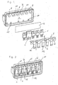
- the exemplary embodiment of an electrical component arrangement illustrated in the figures includes a heat dissipation device 4, which is of trough-shaped design.
- the heat dissipation device may be formed as extruded part or diecast part, in particular made of metal.
- An electrical component or, as shown in the exemplary embodiment, a plurality of electrical components, in particular power components 1, are pressed by means of a spring 2 with heat-conducting contact against a flat surface 3 on the heat dissipation device 4. Between the electrical components 1 and the surface 3 is an insulating film thirteenth
- the spring 2 is designed as a spring comb and has a plurality of finger-shaped spring elements 12, which are connected to one another via a connecting bar 11 with each other.
- the comb-shaped spring 2 is fastened to a fastening device 7 on the heat dissipation device 4.
- the fastening device 7 consists of a plurality of projections 10, which protrude from the surface 3 in the upper region.
- the fixation of the spring 2 is effected by a press fit, which is in each case made in the region of the connecting strip 11 to the projections 10 of the fastening device 7.
- 11 clamping areas 5 and 6 are provided on the spring 2 in the region of the connection bar.
- each projection 10 of the fastening device 7 are each assigned two clamping regions 5 and 6 on the spring 2 in the region of the connecting strip 11.
- the clamping areas 5 and 6 abut opposite surfaces 8 and 9 of a respective projection 10 of the fastening device 7.
- the clamping region 5 is located on an upper surface 8, and the clamping portion 6 abuts a lower surface 9 of a respective projection 10 of the fastening device 7.
- the one below Clamping region 6 is formed on the spring as a clamping edge.
- the upper clamping region 5 is formed flat on the spring and is of edges, in particular a continuous inner edge, as shown in Fig. 1 can be seen limited.
- the two clamping regions 5 and 6 are tilted, in particular between the continuous inner boundary edge of the upper planar clamping region 5 and the lower clamping edge 6.
- This tilting with a guide length L (FIG. Fig. 4 ) is maintained by the spring force of the spring 2.
- the guide length L corresponds to the distance of the clamping seat, which cause the tilting, parallel to the median plane between the two Klemmsitzstellen. Due to this tilting results in a respective clamping seat, with which the spring 2 is fixed to the projections of the fastening device 7.
- This clamping fit also forms the abutment with which the spring elements 12 press on the respective components 1, so that the heat-conducting contact to the surface 3 is made on the heat dissipation device 4.
- the projections 10 of the fastening device 7 are above the juxtaposed components 1.
- recesses 15 may be provided, are plugged into the corresponding projections of a printed circuit board 14, as is made Fig. 3 can be seen.
- the electrical components 1 and additional components may be contacted on the printed circuit board 14.
Landscapes
- Cooling Or The Like Of Electrical Apparatus (AREA)
- Cooling Or The Like Of Semiconductors Or Solid State Devices (AREA)
Claims (3)
- Ensemble d'éléments électriques, comprenant plusieurs éléments électriques fixés sur un dispositif dissipateur de chaleur au moyen d'un ressort (2) réalisé en forme de peigne à ressort qui présente une barrette de liaison (11) au moyen de laquelle des éléments de ressort (12) sont reliés les uns aux autres à leurs extrémités, le ressort (2) étant fixé dans la zone de la barrette de liaison (11) à plusieurs emplacements de fixation au dispositif dissipateur de chaleur et les éléments électriques étant comprimés par les éléments de ressort contre une surface du dispositif dissipateur de chaleur, caractérisé en ce qu'il est prévu à chacun desdits emplacements de fixation une saillie (10) sur la face du dispositif dissipateur de chaleur (4) contre laquelle les éléments électriques (1) sont comprimés, et en ce qu'il est prévu sur la barrette de liaison (11) des bords de serrage repliés (5, 6), avec une longueur de guidage (L) déterminée, qui sont comprimés par une portée de serrage précontrainte par la force du ressort (2) à des emplacements de portées de serrage (5, 6) contre des surfaces opposées (8, 9) de la saillie (10) correspondante, la longueur de guidage étant donnée par la relation L > 2 aµ, où a représente un bras de levier entre un plan médian entre les deux emplacements de portées de serrage (5, 6) et un emplacement d'attaque auquel un élément de ressort (12) correspondant est en prise avec l'élément (1) et µ représente le coefficient de frottement entre les bords de serrage (5, 6) et la saillie (10) correspondante.
- Ensemble d'éléments électriques selon la revendication 1, caractérisé en ce que les éléments de ressort (12) sont en appui sur des éléments électriques (1) disposés les uns à côté des autres.
- Ensemble d'éléments électriques selon la revendication 1 ou la revendication 2, caractérisé en ce que les éléments électriques (1) sont disposés les uns à côté des autres selon une disposition verticale, et en ce que le dispositif de fixation (7) servant à fixer le ressort (2) au moyen de la portée de serrage est disposé au-dessus des éléments électriques (1).
Applications Claiming Priority (1)
| Application Number | Priority Date | Filing Date | Title |
|---|---|---|---|
| DE102005036966A DE102005036966A1 (de) | 2005-08-05 | 2005-08-05 | Elektrische Bauelementanordnung |
Publications (3)
| Publication Number | Publication Date |
|---|---|
| EP1750302A2 EP1750302A2 (fr) | 2007-02-07 |
| EP1750302A3 EP1750302A3 (fr) | 2008-06-25 |
| EP1750302B1 true EP1750302B1 (fr) | 2011-12-21 |
Family
ID=37026999
Family Applications (1)
| Application Number | Title | Priority Date | Filing Date |
|---|---|---|---|
| EP06015827A Not-in-force EP1750302B1 (fr) | 2005-08-05 | 2006-07-28 | Arrangement des éléments électriques |
Country Status (2)
| Country | Link |
|---|---|
| EP (1) | EP1750302B1 (fr) |
| DE (1) | DE102005036966A1 (fr) |
Cited By (1)
| Publication number | Priority date | Publication date | Assignee | Title |
|---|---|---|---|---|
| US11856738B2 (en) * | 2016-01-08 | 2023-12-26 | Lg Innotek Co., Ltd. | Power conversion device having a clip to fix a plurality of switches |
Families Citing this family (1)
| Publication number | Priority date | Publication date | Assignee | Title |
|---|---|---|---|---|
| DE202014002060U1 (de) | 2014-03-06 | 2015-04-08 | HKR Seuffer Automotive GmbH & Co. KG | Kühleinrichtung und Kühlanordnung mit der Kühleinrichtung |
Family Cites Families (13)
| Publication number | Priority date | Publication date | Assignee | Title |
|---|---|---|---|---|
| GB2131623B (en) * | 1982-09-27 | 1985-12-04 | Otter Controls Ltd | Mounting arrangement and spring retainer clip for electronic thermostat |
| DE8606346U1 (de) * | 1986-03-07 | 1986-06-19 | Siemens AG, 1000 Berlin und 8000 München | Kühlkörper zum Ableiten der in mindestens einem thermisch hochbelasteten, auf einer Leiterplatte angeordneten Bauelement anfallenden Verlustwärme an eine gekühlte Gehäusewand |
| US4845590A (en) * | 1987-11-02 | 1989-07-04 | Chrysler Motors Corporation | Heat sink for electrical components |
| US4964198A (en) * | 1988-09-21 | 1990-10-23 | Avvid Engineering, Inc. | V-shaped clip for attaching a semiconductor device to a heat sink |
| US5274153A (en) * | 1991-03-25 | 1993-12-28 | Ethyl Corporation | Continuous process for preparing aluminum alkyls and linear 1-olefins from internal olefins |
| US5274193A (en) | 1992-04-24 | 1993-12-28 | Chrysler Corporation | Heat sink spring and wedge assembly |
| DE19538642A1 (de) * | 1995-10-17 | 1997-04-24 | Kd Ingenieurtechnik Gmbh | Kühl- und Montageanordnung für eine Reihe von Halbleiter-Bauelementen |
| DE19543260C2 (de) * | 1995-11-20 | 2001-09-20 | Robert Seuffer Gmbh & Co | Elektrische Bauelementeanordnung mit mehreren in einem Gehäuse angeordneten elektrischen Bauelementen |
| IT1292590B1 (it) * | 1997-05-30 | 1999-02-08 | El Bo Mec S R L | Dissipatore di calore, in particolare per componenti elettronici. |
| US6081424A (en) * | 1998-05-19 | 2000-06-27 | Chrysler Corporation | Mechanism for removing heat from electronic components |
| FR2780456A1 (fr) * | 1998-06-30 | 1999-12-31 | Valeo Electronique | Dispositif de blocage mecanique d'un element electrique ou electronique sur un support |
| DE20014739U1 (de) * | 2000-08-28 | 2000-12-14 | Fischer-Elektronik GmbH & Co. KG, 58511 Lüdenscheid | Vorrichtung zur Halterung von elektronischen Bauteilen |
| DE10225993A1 (de) * | 2002-06-12 | 2003-12-24 | Bosch Gmbh Robert | Kühlkörper |
-
2005
- 2005-08-05 DE DE102005036966A patent/DE102005036966A1/de not_active Ceased
-
2006
- 2006-07-28 EP EP06015827A patent/EP1750302B1/fr not_active Not-in-force
Cited By (1)
| Publication number | Priority date | Publication date | Assignee | Title |
|---|---|---|---|---|
| US11856738B2 (en) * | 2016-01-08 | 2023-12-26 | Lg Innotek Co., Ltd. | Power conversion device having a clip to fix a plurality of switches |
Also Published As
| Publication number | Publication date |
|---|---|
| EP1750302A2 (fr) | 2007-02-07 |
| EP1750302A3 (fr) | 2008-06-25 |
| DE102005036966A1 (de) | 2007-02-22 |
Similar Documents
| Publication | Publication Date | Title |
|---|---|---|
| EP2010500B1 (fr) | Dispositif de contact de semi-conducteurs de puissance sur une surface réfrigérante | |
| EP1777720B1 (fr) | Élément électrique, notamment support de relais, avec borne élastique et procédé de fabrication | |
| EP2330865B1 (fr) | Dispositif de chauffage électrique | |
| EP1403968B1 (fr) | Borne de raccordement | |
| DE102013109640B4 (de) | Federkraftanschlussklemme und Klemmenbauelement | |
| DE102017129357B4 (de) | Kühlkörper | |
| EP2337425A1 (fr) | Dispositif de chauffage électrique et élément produisant de la chaleur d'un dispositif de chauffage électrique | |
| EP2019268A2 (fr) | Chauffage électrique | |
| DE10340571B3 (de) | Klemme zum Halten von flachen Gegenständen | |
| EP1536519A1 (fr) | Borne de raccordement pour conducteur | |
| EP3843221A1 (fr) | Cadre de support pour un connecteur | |
| EP2242327A1 (fr) | Dispositif de chauffage électrique | |
| EP0928504B1 (fr) | Organe de contact par raccord a double dispositif perce-isolant | |
| EP2297820B1 (fr) | Dispositif métallique de connexion d un conducteur de protection | |
| WO2008077858A1 (fr) | Support | |
| EP1750302B1 (fr) | Arrangement des éléments électriques | |
| DE102010008354A1 (de) | Elektrische Anschlussklemme | |
| DE202012102073U1 (de) | Kontaktleiste | |
| DE19543260A1 (de) | Elektrische Bauelementeanordnung mit mehreren in einem Gehäuse angeordneten elektrischen Bauelementen | |
| EP1248318B1 (fr) | Contact électrique ainsi qu'une douille de lampe et une borne de connexion utilisant un tel contact | |
| DE202023101050U1 (de) | Leiteranschlussklemme | |
| EP1784895A1 (fr) | Module de connexion electrique | |
| EP1926347B1 (fr) | Dispositif de chauffage électrique, en particulier pour un véhicule automobile | |
| EP1905130B1 (fr) | Ressort de contact dans un cadre de support d'un amplificateur d'antenne d'un vehicule | |
| DE10037191C2 (de) | Klemme mit einem Isoliergehäuse |
Legal Events
| Date | Code | Title | Description |
|---|---|---|---|
| PUAI | Public reference made under article 153(3) epc to a published international application that has entered the european phase |
Free format text: ORIGINAL CODE: 0009012 |
|
| AK | Designated contracting states |
Kind code of ref document: A2 Designated state(s): AT BE BG CH CY CZ DE DK EE ES FI FR GB GR HU IE IS IT LI LT LU LV MC NL PL PT RO SE SI SK TR |
|
| AX | Request for extension of the european patent |
Extension state: AL BA HR MK YU |
|
| PUAL | Search report despatched |
Free format text: ORIGINAL CODE: 0009013 |
|
| AK | Designated contracting states |
Kind code of ref document: A3 Designated state(s): AT BE BG CH CY CZ DE DK EE ES FI FR GB GR HU IE IS IT LI LT LU LV MC NL PL PT RO SE SI SK TR |
|
| AX | Request for extension of the european patent |
Extension state: AL BA HR MK RS |
|
| RTI1 | Title (correction) |
Free format text: ARRANGEMENT OF ELECTRICAL ELEMENTS |
|
| 17P | Request for examination filed |
Effective date: 20081103 |
|
| RIN1 | Information on inventor provided before grant (corrected) |
Inventor name: BRAND, MATTHIAS |
|
| AKX | Designation fees paid |
Designated state(s): FR IT |
|
| 17Q | First examination report despatched |
Effective date: 20090205 |
|
| RIN1 | Information on inventor provided before grant (corrected) |
Inventor name: BRAND, MATTHIAS |
|
| REG | Reference to a national code |
Ref country code: DE Ref legal event code: 8566 |
|
| GRAP | Despatch of communication of intention to grant a patent |
Free format text: ORIGINAL CODE: EPIDOSNIGR1 |
|
| GRAS | Grant fee paid |
Free format text: ORIGINAL CODE: EPIDOSNIGR3 |
|
| GRAA | (expected) grant |
Free format text: ORIGINAL CODE: 0009210 |
|
| AK | Designated contracting states |
Kind code of ref document: B1 Designated state(s): FR IT |
|
| PLBE | No opposition filed within time limit |
Free format text: ORIGINAL CODE: 0009261 |
|
| STAA | Information on the status of an ep patent application or granted ep patent |
Free format text: STATUS: NO OPPOSITION FILED WITHIN TIME LIMIT |
|
| 26N | No opposition filed |
Effective date: 20120924 |
|
| PGFP | Annual fee paid to national office [announced via postgrant information from national office to epo] |
Ref country code: IT Payment date: 20120725 Year of fee payment: 7 Ref country code: FR Payment date: 20120803 Year of fee payment: 7 |
|
| REG | Reference to a national code |
Ref country code: FR Ref legal event code: ST Effective date: 20140331 |
|
| PG25 | Lapsed in a contracting state [announced via postgrant information from national office to epo] |
Ref country code: IT Free format text: LAPSE BECAUSE OF NON-PAYMENT OF DUE FEES Effective date: 20130728 Ref country code: FR Free format text: LAPSE BECAUSE OF NON-PAYMENT OF DUE FEES Effective date: 20130731 |