EP2999875B1 - Kraftstoffeinspritzventil - Google Patents
Kraftstoffeinspritzventil Download PDFInfo
- Publication number
- EP2999875B1 EP2999875B1 EP14800450.0A EP14800450A EP2999875B1 EP 2999875 B1 EP2999875 B1 EP 2999875B1 EP 14800450 A EP14800450 A EP 14800450A EP 2999875 B1 EP2999875 B1 EP 2999875B1
- Authority
- EP
- European Patent Office
- Prior art keywords
- control
- control valve
- fuel
- fuel injector
- valve member
- Prior art date
- Legal status (The legal status is an assumption and is not a legal conclusion. Google has not performed a legal analysis and makes no representation as to the accuracy of the status listed.)
- Active
Links
Images



Classifications
-
- F—MECHANICAL ENGINEERING; LIGHTING; HEATING; WEAPONS; BLASTING
- F02—COMBUSTION ENGINES; HOT-GAS OR COMBUSTION-PRODUCT ENGINE PLANTS
- F02M—SUPPLYING COMBUSTION ENGINES IN GENERAL WITH COMBUSTIBLE MIXTURES OR CONSTITUENTS THEREOF
- F02M61/00—Fuel-injectors not provided for in groups F02M39/00 - F02M57/00 or F02M67/00
- F02M61/04—Fuel-injectors not provided for in groups F02M39/00 - F02M57/00 or F02M67/00 having valves, e.g. having a plurality of valves in series
- F02M61/10—Other injectors with elongated valve bodies, i.e. of needle-valve type
-
- F—MECHANICAL ENGINEERING; LIGHTING; HEATING; WEAPONS; BLASTING
- F02—COMBUSTION ENGINES; HOT-GAS OR COMBUSTION-PRODUCT ENGINE PLANTS
- F02F—CYLINDERS, PISTONS OR CASINGS, FOR COMBUSTION ENGINES; ARRANGEMENTS OF SEALINGS IN COMBUSTION ENGINES
- F02F1/00—Cylinders; Cylinder heads
- F02F1/24—Cylinder heads
- F02F1/242—Arrangement of spark plugs or injectors
-
- F—MECHANICAL ENGINEERING; LIGHTING; HEATING; WEAPONS; BLASTING
- F02—COMBUSTION ENGINES; HOT-GAS OR COMBUSTION-PRODUCT ENGINE PLANTS
- F02M—SUPPLYING COMBUSTION ENGINES IN GENERAL WITH COMBUSTIBLE MIXTURES OR CONSTITUENTS THEREOF
- F02M43/00—Fuel-injection apparatus operating simultaneously on two or more fuels, or on a liquid fuel and another liquid, e.g. the other liquid being an anti-knock additive
- F02M43/04—Injectors peculiar thereto
-
- F—MECHANICAL ENGINEERING; LIGHTING; HEATING; WEAPONS; BLASTING
- F02—COMBUSTION ENGINES; HOT-GAS OR COMBUSTION-PRODUCT ENGINE PLANTS
- F02M—SUPPLYING COMBUSTION ENGINES IN GENERAL WITH COMBUSTIBLE MIXTURES OR CONSTITUENTS THEREOF
- F02M45/00—Fuel-injection apparatus characterised by having a cyclic delivery of specific time/pressure or time/quantity relationship
-
- F—MECHANICAL ENGINEERING; LIGHTING; HEATING; WEAPONS; BLASTING
- F02—COMBUSTION ENGINES; HOT-GAS OR COMBUSTION-PRODUCT ENGINE PLANTS
- F02M—SUPPLYING COMBUSTION ENGINES IN GENERAL WITH COMBUSTIBLE MIXTURES OR CONSTITUENTS THEREOF
- F02M45/00—Fuel-injection apparatus characterised by having a cyclic delivery of specific time/pressure or time/quantity relationship
- F02M45/02—Fuel-injection apparatus characterised by having a cyclic delivery of specific time/pressure or time/quantity relationship with each cyclic delivery being separated into two or more parts
- F02M45/04—Fuel-injection apparatus characterised by having a cyclic delivery of specific time/pressure or time/quantity relationship with each cyclic delivery being separated into two or more parts with a small initial part, e.g. initial part for partial load and initial and main part for full load
- F02M45/08—Injectors peculiar thereto
- F02M45/086—Having more than one injection-valve controlling discharge orifices
-
- F—MECHANICAL ENGINEERING; LIGHTING; HEATING; WEAPONS; BLASTING
- F02—COMBUSTION ENGINES; HOT-GAS OR COMBUSTION-PRODUCT ENGINE PLANTS
- F02M—SUPPLYING COMBUSTION ENGINES IN GENERAL WITH COMBUSTIBLE MIXTURES OR CONSTITUENTS THEREOF
- F02M45/00—Fuel-injection apparatus characterised by having a cyclic delivery of specific time/pressure or time/quantity relationship
- F02M45/02—Fuel-injection apparatus characterised by having a cyclic delivery of specific time/pressure or time/quantity relationship with each cyclic delivery being separated into two or more parts
- F02M45/10—Other injectors with multiple-part delivery, e.g. with vibrating valves
-
- F—MECHANICAL ENGINEERING; LIGHTING; HEATING; WEAPONS; BLASTING
- F02—COMBUSTION ENGINES; HOT-GAS OR COMBUSTION-PRODUCT ENGINE PLANTS
- F02M—SUPPLYING COMBUSTION ENGINES IN GENERAL WITH COMBUSTIBLE MIXTURES OR CONSTITUENTS THEREOF
- F02M47/00—Fuel-injection apparatus operated cyclically with fuel-injection valves actuated by fluid pressure
- F02M47/02—Fuel-injection apparatus operated cyclically with fuel-injection valves actuated by fluid pressure of accumulator-injector type, i.e. having fuel pressure of accumulator tending to open, and fuel pressure in other chamber tending to close, injection valves and having means for periodically releasing that closing pressure
- F02M47/027—Electrically actuated valves draining the chamber to release the closing pressure
-
- F—MECHANICAL ENGINEERING; LIGHTING; HEATING; WEAPONS; BLASTING
- F02—COMBUSTION ENGINES; HOT-GAS OR COMBUSTION-PRODUCT ENGINE PLANTS
- F02M—SUPPLYING COMBUSTION ENGINES IN GENERAL WITH COMBUSTIBLE MIXTURES OR CONSTITUENTS THEREOF
- F02M61/00—Fuel-injectors not provided for in groups F02M39/00 - F02M57/00 or F02M67/00
- F02M61/04—Fuel-injectors not provided for in groups F02M39/00 - F02M57/00 or F02M67/00 having valves, e.g. having a plurality of valves in series
- F02M61/042—The valves being provided with fuel passages
- F02M61/045—The valves being provided with fuel discharge orifices
-
- F—MECHANICAL ENGINEERING; LIGHTING; HEATING; WEAPONS; BLASTING
- F02—COMBUSTION ENGINES; HOT-GAS OR COMBUSTION-PRODUCT ENGINE PLANTS
- F02M—SUPPLYING COMBUSTION ENGINES IN GENERAL WITH COMBUSTIBLE MIXTURES OR CONSTITUENTS THEREOF
- F02M61/00—Fuel-injectors not provided for in groups F02M39/00 - F02M57/00 or F02M67/00
- F02M61/04—Fuel-injectors not provided for in groups F02M39/00 - F02M57/00 or F02M67/00 having valves, e.g. having a plurality of valves in series
- F02M61/08—Fuel-injectors not provided for in groups F02M39/00 - F02M57/00 or F02M67/00 having valves, e.g. having a plurality of valves in series the valves opening in direction of fuel flow
-
- F—MECHANICAL ENGINEERING; LIGHTING; HEATING; WEAPONS; BLASTING
- F02—COMBUSTION ENGINES; HOT-GAS OR COMBUSTION-PRODUCT ENGINE PLANTS
- F02M—SUPPLYING COMBUSTION ENGINES IN GENERAL WITH COMBUSTIBLE MIXTURES OR CONSTITUENTS THEREOF
- F02M61/00—Fuel-injectors not provided for in groups F02M39/00 - F02M57/00 or F02M67/00
- F02M61/16—Details not provided for in, or of interest apart from, the apparatus of groups F02M61/02 - F02M61/14
- F02M61/18—Injection nozzles, e.g. having valve seats; Details of valve member seated ends, not otherwise provided for
- F02M61/1806—Injection nozzles, e.g. having valve seats; Details of valve member seated ends, not otherwise provided for characterised by the arrangement of discharge orifices, e.g. orientation or size
- F02M61/182—Discharge orifices being situated in different transversal planes with respect to valve member direction of movement
-
- F—MECHANICAL ENGINEERING; LIGHTING; HEATING; WEAPONS; BLASTING
- F02—COMBUSTION ENGINES; HOT-GAS OR COMBUSTION-PRODUCT ENGINE PLANTS
- F02M—SUPPLYING COMBUSTION ENGINES IN GENERAL WITH COMBUSTIBLE MIXTURES OR CONSTITUENTS THEREOF
- F02M63/00—Other fuel-injection apparatus having pertinent characteristics not provided for in groups F02M39/00 - F02M57/00 or F02M67/00; Details, component parts, or accessories of fuel-injection apparatus, not provided for in, or of interest apart from, the apparatus of groups F02M39/00 - F02M61/00 or F02M67/00; Combination of fuel pump with other devices, e.g. lubricating oil pump
- F02M63/0012—Valves
- F02M63/0059—Arrangements of valve actuators
- F02M63/0064—Two or more actuators acting on two or more valve bodies
-
- F—MECHANICAL ENGINEERING; LIGHTING; HEATING; WEAPONS; BLASTING
- F02—COMBUSTION ENGINES; HOT-GAS OR COMBUSTION-PRODUCT ENGINE PLANTS
- F02D—CONTROLLING COMBUSTION ENGINES
- F02D19/00—Controlling engines characterised by their use of non-liquid fuels, pluralities of fuels, or non-fuel substances added to the combustible mixtures
- F02D19/06—Controlling engines characterised by their use of non-liquid fuels, pluralities of fuels, or non-fuel substances added to the combustible mixtures peculiar to engines working with pluralities of fuels, e.g. alternatively with light and heavy fuel oil, other than engines indifferent to the fuel consumed
- F02D19/0663—Details on the fuel supply system, e.g. tanks, valves, pipes, pumps, rails, injectors or mixers
- F02D19/0686—Injectors
- F02D19/0694—Injectors operating with a plurality of fuels
-
- F—MECHANICAL ENGINEERING; LIGHTING; HEATING; WEAPONS; BLASTING
- F02—COMBUSTION ENGINES; HOT-GAS OR COMBUSTION-PRODUCT ENGINE PLANTS
- F02D—CONTROLLING COMBUSTION ENGINES
- F02D41/00—Electrical control of supply of combustible mixture or its constituents
- F02D41/0025—Controlling engines characterised by use of non-liquid fuels, pluralities of fuels, or non-fuel substances added to the combustible mixtures
-
- F—MECHANICAL ENGINEERING; LIGHTING; HEATING; WEAPONS; BLASTING
- F02—COMBUSTION ENGINES; HOT-GAS OR COMBUSTION-PRODUCT ENGINE PLANTS
- F02D—CONTROLLING COMBUSTION ENGINES
- F02D41/00—Electrical control of supply of combustible mixture or its constituents
- F02D41/0025—Controlling engines characterised by use of non-liquid fuels, pluralities of fuels, or non-fuel substances added to the combustible mixtures
- F02D41/0027—Controlling engines characterised by use of non-liquid fuels, pluralities of fuels, or non-fuel substances added to the combustible mixtures the fuel being gaseous
-
- F—MECHANICAL ENGINEERING; LIGHTING; HEATING; WEAPONS; BLASTING
- F02—COMBUSTION ENGINES; HOT-GAS OR COMBUSTION-PRODUCT ENGINE PLANTS
- F02M—SUPPLYING COMBUSTION ENGINES IN GENERAL WITH COMBUSTIBLE MIXTURES OR CONSTITUENTS THEREOF
- F02M2200/00—Details of fuel-injection apparatus, not otherwise provided for
- F02M2200/21—Fuel-injection apparatus with piezoelectric or magnetostrictive elements
-
- F—MECHANICAL ENGINEERING; LIGHTING; HEATING; WEAPONS; BLASTING
- F02—COMBUSTION ENGINES; HOT-GAS OR COMBUSTION-PRODUCT ENGINE PLANTS
- F02M—SUPPLYING COMBUSTION ENGINES IN GENERAL WITH COMBUSTIBLE MIXTURES OR CONSTITUENTS THEREOF
- F02M2200/00—Details of fuel-injection apparatus, not otherwise provided for
- F02M2200/46—Valves, e.g. injectors, with concentric valve bodies
-
- F—MECHANICAL ENGINEERING; LIGHTING; HEATING; WEAPONS; BLASTING
- F02—COMBUSTION ENGINES; HOT-GAS OR COMBUSTION-PRODUCT ENGINE PLANTS
- F02M—SUPPLYING COMBUSTION ENGINES IN GENERAL WITH COMBUSTIBLE MIXTURES OR CONSTITUENTS THEREOF
- F02M2547/00—Special features for fuel-injection valves actuated by fluid pressure
- F02M2547/003—Valve inserts containing control chamber and valve piston
-
- Y—GENERAL TAGGING OF NEW TECHNOLOGICAL DEVELOPMENTS; GENERAL TAGGING OF CROSS-SECTIONAL TECHNOLOGIES SPANNING OVER SEVERAL SECTIONS OF THE IPC; TECHNICAL SUBJECTS COVERED BY FORMER USPC CROSS-REFERENCE ART COLLECTIONS [XRACs] AND DIGESTS
- Y02—TECHNOLOGIES OR APPLICATIONS FOR MITIGATION OR ADAPTATION AGAINST CLIMATE CHANGE
- Y02T—CLIMATE CHANGE MITIGATION TECHNOLOGIES RELATED TO TRANSPORTATION
- Y02T10/00—Road transport of goods or passengers
- Y02T10/10—Internal combustion engine [ICE] based vehicles
- Y02T10/30—Use of alternative fuels, e.g. biofuels
Definitions
- the present invention relates to a fuel injector suitable for controlling the delivery of two different fuels into an internal combustion engine.
- the invention relates to a fuel injector suitable for injecting a gaseous fuel and a liquid fuel.
- Natural gas can be used in place of diesel to fuel a compression-ignition engine, in which combustion of the fuel occurs as a result of compression of the air-fuel mixture in the cylinder.
- natural gas has a higher auto-ignition temperature than diesel, it can be necessary to initiate combustion with a pilot injection of diesel fuel before introducing the natural gas to the combustion chamber.
- both natural gas and diesel are injected directly into the combustion chamber. Due to the space constraints in an engine cylinder head, it is desirable to inject both fuels using one fuel injector per cylinder. This requires a fuel injector that is specially adapted to keep the two fuels separate within the injector, and to deliver independently the respective fuel at the appropriate time.
- HPDI high-pressure direct injection
- a fuel injector with a concentric twin nozzle arrangement is provided.
- Inner and outer valve needles are engageable at their lower ends with respective valve seats to control the flow of fuel through respective inner and outer sets of outlets.
- the outer valve needle controls the injection of natural gas through the outer set of outlets, and the inner valve needle controls the injection of diesel through the inner set of outlets.
- the outer valve needle is tubular to accommodate the inner valve needle, and the inner set of outlets is formed at a tip of the outer valve needle.
- the inner and outer valve needles are controlled independently by two electromagnetic control valves, which are configured to control the pressure of a control fluid (normally diesel fuel) within respective control chambers for the inner and outer valve needles.
- the control chambers receive the upper ends of the respective needles, so that changing the pressure of the control fluid in each control chamber changes the downward (closing) force on the corresponding needle.
- Gas or diesel fuel pressure acts on downwardly-facing thrust surfaces of the respective needles to generate an upward (opening) force on the needle.
- the pressure of the control fluid in a control chamber is relatively high, the downward force is greater than the upward force and the respective needle remains seated, and when the pressure of the control fluid is relatively low, the upward force overcomes the downward force and the respective needle opens to permit fuel injection through the respective set of outlets.
- Each control chamber is connected to a source of control fluid at relatively high pressure.
- Each control valve is operable to connect the respective control chamber to a low-pressure drain for the control fluid. In this way, opening of each control valve causes a reduction in the pressure of the control fluid in the corresponding control chamber, resulting in opening of the corresponding valve needle.
- the injector is mounted in a bore in the cylinder head of the engine.
- a main body of the injector extends through the bore, so that the tip of the injector protrudes into the respective combustion chamber.
- the maximum diameter of the cylinder head bore, and hence the diameter of the main body of the injector, is constrained by the limited space available in the cylinder head.
- the electromagnetic actuators used to actuate the control valves are generally too large to be accommodated in the main body of the injector. Instead, the actuators and control valves are typically mounted in a side-by-side configuration at the top of the fuel injector, so that they protrude above the cylinder head.
- Injectors of this type therefore have a relatively bulky top end, which takes up space in the region above the cylinder head. It would be desirable to reduce the amount of space taken up by the injectors above the cylinder head, for to create extra space for fuel rails and other engine components. It is against this background that the present invention has been devised.
- US6340121 discloses a fuel injector comprising a nozzle body defining a first bore and an inwardly opening valve member slidable within the first bore, the valve member being engageable with a first seating to control fuel delivery through a first outlet opening provided in the nozzle body.
- WO2012/171119 describes a dual fuel injection valve with concentric needles comprises an inner needle and an outer needle surrounding the inner needle, both needles being located inside the injection valve body.
- the present invention resides in a fuel injector as recited in claim 1.
- a fuel injector 10 is generally elongate in form.
- the fuel injector 10 comprises an injector body 12, also known as a nozzle holder, and a nozzle body 14.
- the injector body 12 and the nozzle body 14 are held together in an end-to-end configuration by a cap nut 16, which is in threaded engagement with the lower end of an injector cap part 17.
- a tip region 18 of the nozzle body 14 includes an outer set of outlets 20 and an inner outlet 22.
- injection of a first fuel through the outer set of outlets 20 is controlled by a first or outer valve needle (not shown in Figures 1 and 2 )
- injection of a second fuel through the inner outlet 22 is controlled by a second or inner valve needle (not shown in Figures 1 and 2 ).
- the injector body 12 is generally cylindrical.
- the injector body 12 comprises a control valve assembly 24, which is shown in more detail and in isolation in Figures 3 and 4 .
- the control valve assembly 24 comprises a first control valve, indicated generally at 26, and a second control valve, indicated generally at 28.
- the first and second control valves 26, 28 are both electromagnetically actuated, and share a common solenoid core member 30.
- the core member 30 is shaped to form a first generally tubular pole piece 32 and a second generally tubular pole piece 34.
- the first and second pole pieces 32, 34 extend in opposite directions from an annular outwardly-directed flange 36.
- a first solenoid coil 38 is disposed around the first pole piece 32, and a second solenoid coil 40 is disposed around the second pole piece 34.
- the core member 30 and the first and second coils 38, 40 are housed within a generally tubular intermediate injector body part 42.
- the intermediate injector body part 42 is closed at its upper end by an upper, generally cylindrical, injector body part 44, and at its lower end by a lower injector body part 46.
- the lower injector body part 46 has a frustoconical upper region and a cylindrical lower region.
- the first control valve 26 includes a control valve member 48 (known hereafter as the first control valve member) that is slidably received in a bore 49 in the upper injector body part 44.
- the first control valve member 48 is attached to a disc-shaped armature 50 that is housed in a recess 52 in the lower face of the upper injector body part 44. In this way, the armature 50 is disposed adjacent to the upper end of the first pole piece 32 of the core member 30.
- a pole ring 54 is disposed around the periphery of the first coil 38, such that the pole ring 54 serves as an outer pole of the first control valve 26.
- the first control valve member 48 is biased into a first position, known as a filling position, by a first biasing spring 56.
- the first biasing spring 56 is engaged with the control valve member 48 at one end, and is supported at its other end by a web 58 of the core member 30 that separates the bores of the first and second pole pieces 32, 34.
- the armature 50 moves towards the first pole piece 32, drawing the first control valve member 48 into a second position, known as a drain position.
- the first control valve member 48 moves downwards, towards the core member 30, as it switches from the filling position to the drain position.
- the second control valve 28 also includes a control valve member 60 (known hereafter as the second control valve member) that is slidably received in a bore 62 in the lower injector body part 46.
- the second control valve member 60 is attached to a disc-shaped armature 64 that is housed in a recess 66 in the upper face of the lower injector body part 46.
- the armature 64 is therefore disposed adjacent to the lower end of the second pole piece 34 of the core member 30.
- the armature 64 of the second control valve 28 has a diameter similar to the diameter of the second pole piece 34, and no outer pole is provided in the second control valve 28.
- the second control valve member 60 is biased into a first position, known as a filling position, by a second biasing spring 68.
- the second biasing spring 68 is engaged with the second control valve member 60 at one end, and is supported at its other end by the web 58 of the core member 30.
- the armature 64 of the second control valve 28 moves towards the second pole piece 34, drawing the second control valve member 60 into a second position, known as a drain position.
- the first and second control valve members 48, 60 are arranged along a common axis, known as a control valve axis. As shown most clearly in Figure 2 , the control valve axis is radially offset from the axis of the nozzle body 14, and hence the axis along which the inner and outer valve needles (not shown in Figure 2 ) are movable.
- the first and second coils 38, 40 are controlled independently by an electronic control unit (not shown). Electrical connections to each of the coils 38, 40 are made through an internal connector 70 housed alongside the core member 30 in the intermediate injector body part 42.
- a bore 72 extends through the upper injector body part 44 and the intermediate injector body part 42 to receive an electrical connector (not shown). The bore 72 extends through relatively thick parts of the walls of the intermediate injector body part 42 and the upper injector body part 44 that are created as a result of the offset position of the control valve axis.
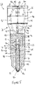
- Figure 5 is a schematic illustration of the fluid connections between the control valve assembly 24, the components within the nozzle body 14, and the external connections in an injector according to another embodiment of the invention. For clarity, many features of the control valve assembly 24 are omitted from Figure 5 ; only the first and second control valve members 48, 60 are shown.
- the injector of Figure 5 is generally similar to the injector described with reference to Figures 1 to 4 , and reference should be made to the above description for an explanation of features not further described below.
- the tip region 18 of the nozzle body 14 comprises a circular aperture 18a through which the tubular outer valve needle 80 protrudes.
- the outer valve needle 80 is engageable with a seating region 82 to control the flow of a first fuel through an outer set of outlets (not shown) downstream of the seating region 82.
- an annular accumulator volume 84 for the first fuel is disposed around the outer valve needle 80.
- the first fuel is supplied to the accumulator volume 84 by way of a supply passage 86 in the wall of the nozzle body 14.
- a supply passage 86 registers with a gallery in the cylinder head from which the first fuel is supplied to the injector.
- Movement of the outer valve needle 80 is controlled hydraulically, by varying the pressure of a control fluid in a first control chamber 88.
- the first control chamber is disposed in the nozzle body 14 at the upper end of the outer valve needle 80. An upper surface of the outer valve needle 80 is exposed to fluid pressure in the first control chamber 88.
- Control fluid is admitted to the first control chamber 88 through a first control fluid inlet passage 90.
- the first control fluid inlet passage 90 includes a restricted orifice or throttle 90a, which serves to limit the flow rate of the control fluid as it flows into the first control chamber 88.
- the first control chamber 88 is connected to the first control valve 26 by way of a first service pathway 92, which comprises a series of interconnecting drillings that extend through the nozzle body 14, the lower injector body part 46, the intermediate injector body part 42 and the upper injector body part 44.
- the service pathway 92 is connected with an annular valve chamber 93 disposed around the upper end 98 of the first control valve 48.
- a control fluid supply pathway 94 comprises a further series of interconnecting drillings that extend through the nozzle body 14, the lower injector body part 46, the intermediate injector body part 42 and the upper injector body part 44.
- the control fluid supply pathway 94 is connected to a second control fluid inlet passage 96 in the nozzle body 14.
- the first and second control fluid inlet passages 90, 96 receive control fluid at relatively high pressure from a gallery in the cylinder head bore (not shown) when the injector is installed.
- a branch 94a of the control fluid supply pathway 94 supplies control fluid to a gallery associated with the first control valve member 48.
- the first control valve member 48 includes a shoulder (not shown) that is engageable with a seating region (not shown) of the first control valve bore 49 to form a first seat of the first control valve member 48.
- the end 98 of the first control valve member 48 is engageable with a seating region defined on the lower surface of the injector cap part 17 (see additionally Figures 1 and 4 ) to form a second seat of the first control valve member 48.
- a drain passage (indicated at 95 in Figure 3 ), formed in the injector cap part 17, is provided downstream of the second seat. The drain passage is connected to a low-pressure drain for the control fluid.
- the shoulder When the first control valve member 48 is in its filling position, the shoulder is disengaged from its seating region, allowing control fluid to flow past the first seat from the gallery into the annular chamber 93 and to the first control chamber 88, through the first service pathway 92. At the same time, the end 98 of the first control valve member 48 is engaged with its seating region, so that control fluid cannot flow from the annular chamber 93 into the drain passage 95 past the second seat. In this way, the control chamber 88 is filled with control fluid at relatively high pressure. The resulting force that acts on the outer valve needle 80 is sufficient to keep the outer valve needle 80 seated, thereby to prevent injection of the first fuel from the injector.
- the shoulder engages with its seating region to stop the flow of control fluid into the first service pathway 92 at the first seat.
- the end 98 of the first control valve member 48 disengages from its seating region to allow control fluid in the first service pathway 92 to flow to the low-pressure drain.
- the rate of outflow of control fluid from the first control chamber 88 to drain exceeds the rate of inflow of control fluid into the first control chamber 88 from the first control fluid inlet passage 90, by virtue of the throttle 90a. In this way, the pressure of control fluid in the first control chamber 88 decreases, allowing the outer valve needle 80 to lift from its seating so as to cause the first fuel in the accumulator volume 84 to be injected through the outer set of outlets.
- the first coil 38 is de-energised so that the first control valve member 48 moves back into its filling position.
- the pressure of the control fluid in the first control chamber 88 rises once again, forcing the outer valve needle 80 into its closed position.
- a return spring 99 is housed in the first control chamber 88 to provide an additional closing force to the outer valve needle 80 that keeps the outer valve needle 80 seated when the injector is not operating.
- the inner valve needle 100 is housed within the bore of the tubular outer valve needle 80, so that the inner and outer valve needles 100, 80 are arranged along a common valve needle axis.
- the inner valve needle 100 is engageable with a seating region 80a at the tip of the outer valve needle 80 to control the flow of a second fuel through an inner orifice or set of orifices (not shown) in the tip of the outer valve needle 80.
- An annular accumulator volume 102 for the second fuel is disposed between the inner valve needle 100 and the outer valve needle 80.
- fuel flow from the accumulator volume 102 through the orifices is prevented, and when the inner valve needle 100 is lifted from its seating region 80a, fuel can pass from the accumulator volume 102 through the orifices for injection into the combustion chamber of the engine.
- the second fuel is supplied to the accumulator volume 102 by way of a supply passage 104 in the wall of the nozzle body 14, which connects with an annular gallery 106 that extends around the outside of the outer valve needle 80.
- a plurality of radial drillings 108 permit the second fuel to flow from the annular gallery 106 through the outer valve needle 80 and into the accumulator volume 102.
- the annular gallery 106 acts as a fluid seal to guard against leakage of the first fuel in the accumulator volume 84 into the first and second control chambers 88, 110. Accordingly, the pressure of the second fuel in the gallery 106 can be maintained at a higher level than the pressure of the first fuel in the accumulator volume 84.
- Movement of the inner valve needle 100 is controlled hydraulically, by varying the pressure of a control fluid in a second control chamber 110.
- the second control chamber 110 is defined at the upper end of the bore of the outer valve needle 80.
- An upper surface of the inner valve needle 100 is exposed to fluid pressure in the second control chamber 110, and an enlarged-diameter piston region 112 of the inner valve needle 100 separates the second control chamber 110 from the accumulator volume 102 for the second fuel.
- Control fluid is admitted to the second control chamber 110 through a third control fluid inlet passage 114.
- the third control fluid inlet passage 114 includes a restricted orifice or throttle 114a, which serves to limit the flow rate of the control fluid as it flows into the second control chamber 110.
- the third control fluid inlet passage 114 receives control fluid at relatively high pressure from the gallery in the cylinder head bore (not shown) when the injector is installed.
- the second control chamber 110 is connected to the second control valve 28 by way of a second service pathway 116, which is formed by drillings that extend through the nozzle body 14 and into the lower injector body part 46.
- a plurality of radial drillings 117 in the outer valve needle 80 are provided to permit fluid communication between the second control chamber 110 and the third control fluid inlet passage 114 and the second service pathway 116.
- a branch 94b of the control fluid supply pathway 94 supplies control fluid to a gallery 94c associated with the second control valve member 60.
- the second control valve member 60 includes a shoulder (not shown) that is engageable with a seating region (not shown) of the second control valve bore 62 to form a first seat of the second control valve member 60.
- the end 118 of the second control valve member 60 is engageable with a seating region defined on the upper surface of the nozzle body 14 to form a second seat of the second control valve member 60.
- a drain passage 120, formed in the nozzle body 14, is provided downstream of the second seat. The drain passage 120 is connected to a low-pressure drain for the control fluid.
- the operation of the second valve needle 100 is similar to the operation of the first valve needle 80.
- the shoulder is disengaged from its seating region, allowing control fluid to flow past the first seat from the gallery 94c to the second control chamber 110, through the second service pathway 116.
- the end 118 of the second control valve member 60 is engaged with its seating region, so that control fluid cannot flow into the drain passage 120 past the second seat.
- the second control chamber 110 is filled with control fluid at relatively high pressure.
- the resulting force that acts on the inner valve needle 100 is sufficient to keep the inner valve needle 100 seated, thereby to prevent injection of the second fuel from the injector.
- the shoulder engages with its seating region to stop the flow of control fluid from the gallery 84c into the second service pathway 116 at the first seat.
- the end 118 of the second control valve member 60 disengages from its seating region to allow control fluid in the second service pathway 116 to flow to the low-pressure drain by way of the drain passage 120.
- the rate of outflow of control fluid from the second control chamber 110 to drain exceeds the rate of inflow of control fluid into the first control chamber 110 from the third control fluid inlet passage 114, by virtue of the throttle 114a. In this way, the pressure of control fluid in the second control chamber 110 decreases, allowing the inner valve needle 100 to lift from its seating 80a so as to cause the second fuel in the accumulator volume 102 to be injected through the orifices.
- the second coil 40 is de-energised so that the second control valve member 60 moves back into its filling position.
- the pressure of the control fluid in the second control chamber 110 rises once again, forcing the inner valve needle 100 into its closed position.
- a return spring 122 is housed in the second control chamber 110 to provide an additional closing force to the inner valve needle 100 that keeps the inner valve needle 100 seated when the injector is not operating.
- the first control valve member 48 has a larger diameter than the second control valve member 60. As a result, a higher rate of flow of control fluid is possible through the first control valve 26 in each position than through the second control valve 28. This reflects the relative volumes of the first and second control chambers 88, 110.
- first and second control valve members 48, 60 are arranged along a common control valve axis that is offset from the common valve needle axis along an offset direction that lies normal to the plane of the figure.
- first and second control valves By arranging the first and second control valves such that the first and second control valve members lie along a common control valve axis, and by providing a common core member for both valves, the valves can be housed within the injector body in a space-efficient manner.
- the use of a common core member also facilitates the use of an internal integrated electrical connector.
- the first and second control valves are of the "balanced valve” type.
- the first and second control valve members 48, 60 are configured such that the forces that act on the valve members due to the control fluid are substantially hydraulically balanced.
- the first control valve member 48 comprises a through-bore 48a, as shown most clearly in Figure 3 .
- the through bore 48a communicates with the low-pressure drain passage 95, so that low-pressure control fluid is admitted to the bores of the first and second pole pieces 32, 34.
- both ends of the first control valve member 48 are exposed to control fluid at low pressure.
- the end 98 of the first control valve member 48 is shaped to expose a frustoconical surface with a projected area in a plane normal to the control valve axis that is equal to the area presented in the same plane by the opposite (lower) end of the first control valve member 48. Equal pressures therefore act on equal areas of the first control valve member 48, and no net hydraulic force is generated when the first control valve member 48 is in its filling position.
- both ends of the second control valve member 60 are exposed to low-pressure drain fluid.
- An aperture (not shown) in the web 58 admits low-pressure control fluid to the bore of the second pole piece 34 to act on the upper end of the second control valve member 60.
- the lower end of the second control valve member 60 is exposed to control fluid at the same low pressure in the drain passage 120 (see Figure 5 ), and again the projected areas of each end of the second control valve member 60 are equal so that no net hydraulic force acts on the second control valve member 60 when it is in its filling position.
- valves can be packaged within the diametric envelope of the injector body and therefore housed within the cylinder head bore in use. This significantly reduces the amount of space occupied by the injector in the congested region above the cylinder head, giving more room to house the valve train and other engine components.
- control valves can be mounted relatively close to their associated control chambers, which minimises the hydraulic volume of the control circuit and therefore helps to achieve good needle response and control.
- hydraulically balanced valves are not sensitive to the pressure of the control fluid. This means that they remain operable over a wide range of flow rates and operating pressures, and that the same design of control valve assembly can be used in multiple applications.
- both the first control valve 26 and the second control valve 28 are "three-way" valves.
- each control valve 26, 28 serves to connect the respective control chamber 88, 110 to a low-pressure drain when in the drain position, and to connect the respective control chamber 88, 110 to a high-pressure source of control fluid when in the filling position.
- This flow of control fluid into the control chambers 88, 110 augments the flow of control fluid into the control chambers through the first and third control fluid inlet passages 90, 114, leading to rapid needle closure.
- one or both of the first and second control valves 26, 28 may be configured as "two-way" valves.
- the valve serves only to connect the respective control chamber 88, 110 to the low-pressure drain and does not provide a connection to a source of high-pressure control fluid. Instead, re-filling of the respective control chamber 88, 110 occurs only through the first or the third control fluid inlet passages 90, 114.
- Figure 6 illustrates schematically the control valve assemblies used in three possible variations of the invention.
- Figure 6(a) shows the control valve assembly of the embodiment of Figure 5 , in which both the first control valve 26 and the second control valve 28 are of the three-way type. As explained above, in this configuration it is necessary to provide a control fluid supply passage 94 that extends through the whole of the control valve assembly 24.
- Figure 6(b) shows a control valve assembly 224 in which the first control valve 226 is of the two-way type, and the second control valve 228 is of the three-way type.
- the control fluid supply passage 294 extends only within the lower body housing 246, where it supplies control fluid to the second control valve member 260 by way of a branch 294b.
- the control fluid supply passage 294 does not extend into the intermediate body housing 242 or the upper body housing 244, thereby reducing the steps involved in manufacturing the injector, and creating more space for other components in the injector body.
- the variant of Figure 6(b) can be useful, therefore, when it is desirable to maintain optimum control of the injection duration for the second fuel but when it is acceptable to compromise control of the injection duration for the first fuel to reduce manufacturing costs or to make use of the space saving.
- Figure 6(c) shows a control valve assembly 324 in which both the first control valve 326 and the second control valve 328 are of the two-way type. In this configuration, there is no need for a control fluid supply passage. Accordingly, compared to the variant of Figure 6(c) , the variant of 6(a) is considerably simpler and cheaper to manufacture and offers more space in the lower, intermediate and upper injector body components 346, 342, 344.
- control valves used in the above-described embodiments of the invention can be of any suitable type.
- Examples of control valve assemblies with a common core member suitable for adaptation for use in the present invention can be found in, for example, the Applicant's European Patents EP 0987431 and EP 1670005 .
- Examples of balanced three-way control valves suitable for use in the present invention can be found in, for example, the Applicant's European Patents EP 1541860 , EP 1604104 , EP 1988276 and EP 2290219 .
- balanced two-way control valves suitable for use in the present invention can be found in, for example, the Applicant's European Patents EP 0740068 , EP 0957262 and EP 1835171 .
- the first control valve has a relatively large-diameter armature and an outer pole
- the second control valve has a relatively small-diameter armature and no outer pole. It will be appreciated that the first control valve could instead have a relatively small-diameter armature and no outer pole, and/or the second control valve could have a relatively large-diameter armature with an outer pole.
- first and second control valves could have separate core members.
- the first and second control valves could be axially spaced apart along the length of the fuel injector.
- the first control valve is mounted at an upper end of the injector, remote from the nozzle body, and the second control valve is mounted in the injector body close to the nozzle body. In this configuration, the first control is housed outside the cylinder head bore when the injector is installed in the engine.
- the present invention finds particular application when the first fuel is a gaseous fuel, such as natural gas, and the second fuel is a liquid fuel, such as diesel.
- the first or second fuel may also be used as the control fluid.
- the second fuel is diesel and is used as the control fluid.
Landscapes
- Engineering & Computer Science (AREA)
- Chemical & Material Sciences (AREA)
- Combustion & Propulsion (AREA)
- Mechanical Engineering (AREA)
- General Engineering & Computer Science (AREA)
- Physics & Mathematics (AREA)
- Fluid Mechanics (AREA)
- Fuel-Injection Apparatus (AREA)
Claims (14)
- Kraftstoffeinspritzventil (10), das ausgelegt ist, um zwei Kraftstoffe innerhalb des Kraftstoffeinspritzventils getrennt zu halten und den jeweiligen Kraftstoff separat in einen Verbrennungsmotor abzugeben, umfassend:eine erste Ventilnadel (80) mit einer Bohrung zum Aufnehmen einer zweiten Ventilnadel (100), wobei die erste Ventilnadel angeordnet ist, um die Einspritzung eines ersten Kraftstoffs zu steuern, der über einen ersten Kraftstoffversorgungskanal (86) innerhalb des Kraftstoffeinspritzventils zugeführt wird, und die zweite Ventilnadel (100) angeordnet ist, um die Einspritzung eines zweiten Kraftstoffs zu steuern, der über einen zweiten Kraftstoffversorgungskanal (104) innerhalb des Kraftstoffeinspritzventils getrennt von dem ersten Kraftstoffversorgungskanal zugeführt wird;eine erste und zweite Steuerkammer (88, 110), die der ersten bzw. zweiten Ventilnadel (80, 100) zugeordnet sind;ein erstes Steuerventil (26), das ein erstes Steuerventilelement (48) umfasst und angeordnet ist, um den Druck eines Steuerfluids in der ersten Steuerkammer (88) zu verändern, um eine Öffnungs- und Schließbewegung der ersten Ventilnadel (80) zu bewirken; undein zweites Steuerventil (28), das ein zweites Steuerventilelement (60) umfasst und angeordnet ist, um den Steuerfluiddruck in der zweiten Steuerkammer (110) zu verändern, um eine Öffnungs- und Schließbewegung der zweiten Ventilnadel (100) zu bewirken;wobei sowohl das erste als auch das zweite Steuerventil (26, 28) in einem allgemein zylindrischen Körperabschnitt (42, 44, 46) des Einspritzventils (10) untergebracht sind, unddadurch gekennzeichnet, dass das erste und zweite Steuerventilelement (48, 60) für eine lineare Bewegung entlang einer gemeinsamen Steuerventilachse angeordnet sind, die von einer Mittelachse des Einspritzventilkörperabschnitts (42, 44, 46) versetzt und parallel zu dieser ist.
- Kraftstoffeinspritzventil nach Anspruch 1, wobei der erste Kraftstoff ein gasförmiger Kraftstoff ist und wobei der zweite Kraftstoff ein flüssiger Kraftstoff ist.
- Kraftstoffeinspritzventil nach Anspruch 2, wobei das Steuerfluid der zweite Kraftstoff ist.
- Kraftstoffeinspritzventil nach einem der vorhergehenden Ansprüche, wobei der Körperabschnitt (42, 44, 46) des Einspritzventils (10) angeordnet ist, um im Einsatz in eine Zylinderkopfbohrung des Motors zu passen.
- Kraftstoffeinspritzventil nach einem der vorhergehenden Ansprüche, wobei die Steuerventilelemente (48, 60) im Wesentlichen hydraulisch ausgeglichen sind.
- Kraftstoffeinspritzventil nach einem der vorhergehenden Ansprüche, wobei die erste und die zweite Ventilnadel (80, 100) entlang einer gemeinsamen Ventilnadelachse bewegbar sind.
- Kraftstoffeinspritzventil nach Anspruch 6, wobei die Steuerventilachse von der Ventilnadelachse versetzt und parallel zu dieser ist.
- Kraftstoffeinspritzventil nach einem der vorhergehenden Ansprüche, umfassend eine Steuerventilbaugruppe (24), die ein gemeinsames Kernelement (30), eine erste Magnetspule (38) zum Betätigen des ersten Steuerventils (26) und eine zweite Magnetspule (40) zum Betätigen des zweiten Steuerventils (28) beinhaltet.
- Kraftstoffeinspritzventil nach Anspruch 8, ferner umfassend einen inneren Verbinder (70), der zumindest teilweise in dem allgemein zylindrischen Körperabschnitt (42, 44, 46) des Einspritzventils (10) neben dem gemeinsamen Kernelement (30) untergebracht ist, um die erste und zweite Magnetspule (38, 40) mit einer elektrischen Steuereinheit elektrisch zu verbinden.
- Kraftstoffeinspritzventil nach einem der vorhergehenden Ansprüche, wobei das erste Steuerventilelement (48) und das zweite Steuerventilelement (60) jeweils zwischen einer Füllposition, in der das jeweilige Steuerventilelement (48, 60) auf einem Ventilsitz aufliegt, um eine Verbindung zwischen der jeweiligen Steuerkammer (88, 110) und einem Niederdruckablauf für das Steuerfluid zu verhindern, und einer Ablaufposition, in der das jeweilige Steuerventilelement (48, 60) von dem Ventilsitz abgehoben ist, um eine Verbindung zwischen der jeweiligen Steuerkammer (88, 110) und dem Niederdruckablauf zuzulassen, bewegbar sind.
- Kraftstoffeinspritzventil nach Anspruch 10, wobei das erste Ventilelement (48) von seiner Füllposition zu seiner Ablaufposition in einer ersten Richtung bewegbar ist und wobei das zweite Ventilelement (60) von seiner Füllposition zu seiner Ablaufposition in einer zweiten Richtung entgegengesetzt zur ersten Richtung bewegbar ist.
- Kraftstoffeinspritzventil nach Anspruch 10 oder Anspruch 11, wobei das erste Steuerventilelement (48) einen größeren Durchmesser als das zweite Steuerventilelement (60) aufweist.
- Kraftstoffeinspritzventil nach einem der Ansprüche 10 bis 12, wobei das erste Steuerventil (26) angeordnet ist, um einen Fluidstrom von einer Steuerfluidquelle zu der ersten Steuerkammer (88) zu regeln, sodass, wenn das erste Steuerventilelement (48) in seiner Füllposition ist, ein Fluidfluss von der Steuerfluidquelle zu der ersten Steuerkammer (88) zugelassen ist, und wenn sich das erste Steuerventilelement (48) in seiner Ablaufposition befindet, ein Fluidfluss von der Steuerfluidquelle zu der ersten Steuerkammer (88) verhindert ist.
- Kraftstoffeinspritzventil nach einem der Ansprüche 10 bis 13, wobei das zweite Steuerventil (28) angeordnet ist, um einen Fluidstrom von einer Steuerfluidquelle zu der zweiten Steuerkammer (110) zu regeln, sodass, wenn das zweite Steuerventilelement (60) in seiner Füllposition ist, ein Fluidfluss von der Steuerfluidquelle zu der zweiten Steuerkammer (110) zugelassen ist, und wenn sich das zweite Steuerventilelement (60) in seiner Ablaufposition befindet, ein Fluidfluss von der Steuerfluidquelle zu der zweiten Steuerkammer (110) verhindert ist.
Applications Claiming Priority (2)
| Application Number | Priority Date | Filing Date | Title |
|---|---|---|---|
| GBGB1309118.6A GB201309118D0 (en) | 2013-05-21 | 2013-05-21 | Fuel Injector |
| PCT/CA2014/050468 WO2014186891A1 (en) | 2013-05-21 | 2014-05-21 | Fuel injector |
Publications (3)
| Publication Number | Publication Date |
|---|---|
| EP2999875A1 EP2999875A1 (de) | 2016-03-30 |
| EP2999875A4 EP2999875A4 (de) | 2016-11-16 |
| EP2999875B1 true EP2999875B1 (de) | 2022-07-06 |
Family
ID=48747083
Family Applications (1)
| Application Number | Title | Priority Date | Filing Date |
|---|---|---|---|
| EP14800450.0A Active EP2999875B1 (de) | 2013-05-21 | 2014-05-21 | Kraftstoffeinspritzventil |
Country Status (6)
| Country | Link |
|---|---|
| US (1) | US10294908B2 (de) |
| EP (1) | EP2999875B1 (de) |
| JP (1) | JP6336045B2 (de) |
| CN (1) | CN105229295B (de) |
| GB (1) | GB201309118D0 (de) |
| WO (1) | WO2014186891A1 (de) |
Families Citing this family (13)
| Publication number | Priority date | Publication date | Assignee | Title |
|---|---|---|---|---|
| EP3061951A1 (de) | 2015-02-25 | 2016-08-31 | AVL MTC Motortestcenter AB | Kraftstoffeinspritzeinheit |
| CN105526024B (zh) * | 2016-01-13 | 2017-10-20 | 西华大学 | 一种适用于缸内直喷气体燃料的喷射器 |
| GB2554359B (en) * | 2016-09-21 | 2020-03-18 | Delphi Tech Ip Ltd | Dual fuel injector |
| GB2559560B (en) * | 2017-02-08 | 2020-06-17 | Delphi Tech Ip Ltd | Control valve arrangement for a dual fuel injector |
| GB2569627B (en) * | 2017-12-21 | 2020-04-15 | Delphi Tech Ip Ltd | Fuel injector with a 3-way valve assembly for filling or draining a control chamber through first and second throttles |
| JP2020139435A (ja) | 2019-02-27 | 2020-09-03 | 株式会社デンソー | 流体噴射装置 |
| JP2020159333A (ja) | 2019-03-28 | 2020-10-01 | 株式会社デンソー | 流体噴射装置及び流体噴射システム |
| USD934298S1 (en) | 2020-01-29 | 2021-10-26 | Caterpillar Inc. | Injector |
| USD934299S1 (en) | 2020-01-29 | 2021-10-26 | Caterpillar Inc. | Injector |
| JP2024539423A (ja) * | 2021-11-20 | 2024-10-28 | クワントロジック コーポレーション | デュアル燃料燃焼のための噴射器、方法及びシステム |
| CN114233545B (zh) * | 2022-01-06 | 2022-10-11 | 一汽解放汽车有限公司 | 一种双燃料喷射器及发动机 |
| GB2628376B (en) * | 2023-03-21 | 2025-04-23 | Phinia Delphi Luxembourg Sarl | Dual-fuel injector |
| WO2025039074A1 (en) * | 2023-08-18 | 2025-02-27 | Hpdi Technology Limited Partnership | Fuel injector |
Family Cites Families (25)
| Publication number | Priority date | Publication date | Assignee | Title |
|---|---|---|---|---|
| US5722373A (en) * | 1993-02-26 | 1998-03-03 | Paul; Marius A. | Fuel injector system with feed-back control |
| GB9508623D0 (en) | 1995-04-28 | 1995-06-14 | Lucas Ind Plc | "Fuel injection nozzle" |
| GB9810208D0 (en) | 1998-05-13 | 1998-07-08 | Lucas Ind Plc | Fuel injector |
| US6073862A (en) | 1998-09-16 | 2000-06-13 | Westport Research Inc. | Gaseous and liquid fuel injector |
| US6761325B2 (en) * | 1998-09-16 | 2004-07-13 | Westport Research Inc. | Dual fuel injection valve and method of operating a dual fuel injection valve |
| GB9820237D0 (en) | 1998-09-18 | 1998-11-11 | Lucas Ind Plc | Fuel injector |
| GB9922408D0 (en) * | 1999-09-23 | 1999-11-24 | Lucas Ind Plc | Fuel injector |
| US6598584B2 (en) * | 2001-02-23 | 2003-07-29 | Clean Air Partners, Inc. | Gas-fueled, compression ignition engine with maximized pilot ignition intensity |
| GB0215490D0 (en) | 2002-07-04 | 2002-08-14 | Delphi Tech Inc | Control valve arrangement |
| ATE366359T1 (de) | 2003-12-12 | 2007-07-15 | Delphi Tech Inc | Einspritzventil mit steuerungsventil, das den druck im steuerungsraum steuert |
| DE102004017305A1 (de) * | 2004-04-08 | 2005-10-27 | Robert Bosch Gmbh | Kraftstoffeinspritzeinrichtung für Brennkraftmaschinen mit direkt ansteuerbaren Düsennadeln |
| JP2006170206A (ja) | 2004-12-13 | 2006-06-29 | Delphi Technologies Inc | 燃料噴射装置に用いられるアクチュエータ装置 |
| US7219649B2 (en) | 2005-08-10 | 2007-05-22 | Caterpillar Inc | Engine system and method of operating same over multiple engine load ranges |
| JP4535037B2 (ja) | 2006-02-08 | 2010-09-01 | 株式会社デンソー | インジェクタおよび燃料噴射装置 |
| ATE390554T1 (de) | 2006-03-15 | 2008-04-15 | Delphi Tech Inc | Verbesserte steuerventilanordnung |
| GB0801997D0 (en) | 2007-05-01 | 2008-03-12 | Delphi Tech Inc | Fuel injector |
| JP4725564B2 (ja) | 2007-08-31 | 2011-07-13 | トヨタ自動車株式会社 | 内燃機関の燃料噴射装置及びその燃料噴射弁 |
| ATE556216T1 (de) | 2007-10-18 | 2012-05-15 | Delphi Tech Holding Sarl | Kraftstoffeinspritzdüse |
| EP2060774A1 (de) | 2007-11-16 | 2009-05-20 | Delphi Technologies, Inc. | Kraftstoffeinspritzdüse |
| CA2633846C (en) | 2008-06-27 | 2009-12-29 | Westport Power Inc. | Fuel injection valve and method for co-injecting a liquid and a gaseous fuel into the combustion chamber of an internal combustion engine |
| EP2290219B1 (de) | 2009-08-26 | 2013-01-23 | Delphi Technologies Holding S.à.r.l. | Dreiwege-Steuerventil |
| US8967502B2 (en) * | 2011-05-11 | 2015-03-03 | Caterpillar Inc. | Dual fuel injector and engine using same |
| CA2743043C (en) * | 2011-06-14 | 2012-09-18 | Westport Power Inc. | Dual fuel injection valve |
| US8944027B2 (en) | 2011-06-21 | 2015-02-03 | Caterpillar Inc. | Dual fuel injection compression ignition engine and method of operating same |
| US9453483B2 (en) | 2011-08-30 | 2016-09-27 | Caterpillar Inc. | Fuel injector for dual fuel common rail system |
-
2013
- 2013-05-21 GB GBGB1309118.6A patent/GB201309118D0/en not_active Ceased
-
2014
- 2014-05-21 WO PCT/CA2014/050468 patent/WO2014186891A1/en not_active Ceased
- 2014-05-21 CN CN201480029000.2A patent/CN105229295B/zh active Active
- 2014-05-21 JP JP2016514226A patent/JP6336045B2/ja active Active
- 2014-05-21 US US14/892,978 patent/US10294908B2/en active Active
- 2014-05-21 EP EP14800450.0A patent/EP2999875B1/de active Active
Also Published As
| Publication number | Publication date |
|---|---|
| EP2999875A1 (de) | 2016-03-30 |
| JP6336045B2 (ja) | 2018-06-06 |
| JP2016519249A (ja) | 2016-06-30 |
| EP2999875A4 (de) | 2016-11-16 |
| WO2014186891A1 (en) | 2014-11-27 |
| US10294908B2 (en) | 2019-05-21 |
| US20160115924A1 (en) | 2016-04-28 |
| CN105229295A (zh) | 2016-01-06 |
| CN105229295B (zh) | 2019-05-31 |
| GB201309118D0 (en) | 2013-07-03 |
Similar Documents
| Publication | Publication Date | Title |
|---|---|---|
| EP2999875B1 (de) | Kraftstoffeinspritzventil | |
| EP2999876B1 (de) | Kraftstoffeinspritzventil | |
| US10767611B2 (en) | Fuel injector | |
| EP2304218B1 (de) | Einspritzventil und verfahren zur gemeinsamen injektion einer flüssigkeit und eines gasförmigen kraftstoffes in die brennkammer eines verbrennungsmotors | |
| EP1448884B1 (de) | Einspritzventil für zwei kraftstoffe und verfahren zu dessen steuerung | |
| US6557779B2 (en) | Variable spray hole fuel injector with dual actuators | |
| US9624845B2 (en) | Dual fuel injector and engine using same | |
| CN103925133B (zh) | 缸内动态气体混合燃料喷射器和双燃料发动机以及操作发动机的方法 | |
| EP3268600B1 (de) | Hydraulisch betätigter injektor für gasförmigen brennstoff | |
| EP2999874B1 (de) | Kraftstoffeinspritzventil | |
| EP2386745B1 (de) | Kraftstoffinjektor für Verbrennungsmotoren | |
| CN105545525B (zh) | 用于气体燃料的端口喷射系统 | |
| US20230024509A1 (en) | Injector apparatus |
Legal Events
| Date | Code | Title | Description |
|---|---|---|---|
| PUAI | Public reference made under article 153(3) epc to a published international application that has entered the european phase |
Free format text: ORIGINAL CODE: 0009012 |
|
| 17P | Request for examination filed |
Effective date: 20151203 |
|
| AK | Designated contracting states |
Kind code of ref document: A1 Designated state(s): AL AT BE BG CH CY CZ DE DK EE ES FI FR GB GR HR HU IE IS IT LI LT LU LV MC MK MT NL NO PL PT RO RS SE SI SK SM TR |
|
| AX | Request for extension of the european patent |
Extension state: BA ME |
|
| DAX | Request for extension of the european patent (deleted) | ||
| A4 | Supplementary search report drawn up and despatched |
Effective date: 20161018 |
|
| RIC1 | Information provided on ipc code assigned before grant |
Ipc: F02M 61/18 20060101ALI20161012BHEP Ipc: F02M 45/00 20060101ALI20161012BHEP Ipc: F02M 63/00 20060101ALI20161012BHEP Ipc: F02M 43/04 20060101AFI20161012BHEP Ipc: F02M 45/10 20060101ALI20161012BHEP Ipc: F02M 61/04 20060101ALI20161012BHEP Ipc: F02D 19/08 20060101ALI20161012BHEP Ipc: F02M 25/00 20060101ALI20161012BHEP Ipc: F02M 61/08 20060101ALI20161012BHEP Ipc: F02D 41/38 20060101ALI20161012BHEP Ipc: F02M 43/00 20060101ALI20161012BHEP |
|
| RAP1 | Party data changed (applicant data changed or rights of an application transferred) |
Owner name: WESTPORT POWER INC. Owner name: DELPHI TECHNOLOGIES IP LIMITED |
|
| STAA | Information on the status of an ep patent application or granted ep patent |
Free format text: STATUS: EXAMINATION IS IN PROGRESS |
|
| 17Q | First examination report despatched |
Effective date: 20190719 |
|
| GRAJ | Information related to disapproval of communication of intention to grant by the applicant or resumption of examination proceedings by the epo deleted |
Free format text: ORIGINAL CODE: EPIDOSDIGR1 |
|
| GRAP | Despatch of communication of intention to grant a patent |
Free format text: ORIGINAL CODE: EPIDOSNIGR1 |
|
| STAA | Information on the status of an ep patent application or granted ep patent |
Free format text: STATUS: GRANT OF PATENT IS INTENDED |
|
| GRAJ | Information related to disapproval of communication of intention to grant by the applicant or resumption of examination proceedings by the epo deleted |
Free format text: ORIGINAL CODE: EPIDOSDIGR1 |
|
| GRAP | Despatch of communication of intention to grant a patent |
Free format text: ORIGINAL CODE: EPIDOSNIGR1 |
|
| GRAC | Information related to communication of intention to grant a patent modified |
Free format text: ORIGINAL CODE: EPIDOSCIGR1 |
|
| RAP3 | Party data changed (applicant data changed or rights of an application transferred) |
Owner name: DELPHI TECHNOLOGIES IP LIMITED Owner name: WESTPORT FUEL SYSTEMS CANADA INC. |
|
| INTG | Intention to grant announced |
Effective date: 20210107 |
|
| INTG | Intention to grant announced |
Effective date: 20220107 |
|
| GRAS | Grant fee paid |
Free format text: ORIGINAL CODE: EPIDOSNIGR3 |
|
| GRAA | (expected) grant |
Free format text: ORIGINAL CODE: 0009210 |
|
| STAA | Information on the status of an ep patent application or granted ep patent |
Free format text: STATUS: THE PATENT HAS BEEN GRANTED |
|
| AK | Designated contracting states |
Kind code of ref document: B1 Designated state(s): AL AT BE BG CH CY CZ DE DK EE ES FI FR GB GR HR HU IE IS IT LI LT LU LV MC MK MT NL NO PL PT RO RS SE SI SK SM TR |
|
| REG | Reference to a national code |
Ref country code: GB Ref legal event code: FG4D |
|
| REG | Reference to a national code |
Ref country code: AT Ref legal event code: REF Ref document number: 1503035 Country of ref document: AT Kind code of ref document: T Effective date: 20220715 Ref country code: CH Ref legal event code: EP |
|
| REG | Reference to a national code |
Ref country code: DE Ref legal event code: R096 Ref document number: 602014084241 Country of ref document: DE |
|
| REG | Reference to a national code |
Ref country code: IE Ref legal event code: FG4D |
|
| REG | Reference to a national code |
Ref country code: LT Ref legal event code: MG9D |
|
| REG | Reference to a national code |
Ref country code: NL Ref legal event code: MP Effective date: 20220706 |
|
| PG25 | Lapsed in a contracting state [announced via postgrant information from national office to epo] |
Ref country code: SE Free format text: LAPSE BECAUSE OF FAILURE TO SUBMIT A TRANSLATION OF THE DESCRIPTION OR TO PAY THE FEE WITHIN THE PRESCRIBED TIME-LIMIT Effective date: 20220706 Ref country code: RS Free format text: LAPSE BECAUSE OF FAILURE TO SUBMIT A TRANSLATION OF THE DESCRIPTION OR TO PAY THE FEE WITHIN THE PRESCRIBED TIME-LIMIT Effective date: 20220706 Ref country code: PT Free format text: LAPSE BECAUSE OF FAILURE TO SUBMIT A TRANSLATION OF THE DESCRIPTION OR TO PAY THE FEE WITHIN THE PRESCRIBED TIME-LIMIT Effective date: 20221107 Ref country code: NO Free format text: LAPSE BECAUSE OF FAILURE TO SUBMIT A TRANSLATION OF THE DESCRIPTION OR TO PAY THE FEE WITHIN THE PRESCRIBED TIME-LIMIT Effective date: 20221006 Ref country code: NL Free format text: LAPSE BECAUSE OF FAILURE TO SUBMIT A TRANSLATION OF THE DESCRIPTION OR TO PAY THE FEE WITHIN THE PRESCRIBED TIME-LIMIT Effective date: 20220706 Ref country code: LV Free format text: LAPSE BECAUSE OF FAILURE TO SUBMIT A TRANSLATION OF THE DESCRIPTION OR TO PAY THE FEE WITHIN THE PRESCRIBED TIME-LIMIT Effective date: 20220706 Ref country code: LT Free format text: LAPSE BECAUSE OF FAILURE TO SUBMIT A TRANSLATION OF THE DESCRIPTION OR TO PAY THE FEE WITHIN THE PRESCRIBED TIME-LIMIT Effective date: 20220706 Ref country code: FI Free format text: LAPSE BECAUSE OF FAILURE TO SUBMIT A TRANSLATION OF THE DESCRIPTION OR TO PAY THE FEE WITHIN THE PRESCRIBED TIME-LIMIT Effective date: 20220706 Ref country code: ES Free format text: LAPSE BECAUSE OF FAILURE TO SUBMIT A TRANSLATION OF THE DESCRIPTION OR TO PAY THE FEE WITHIN THE PRESCRIBED TIME-LIMIT Effective date: 20220706 |
|
| REG | Reference to a national code |
Ref country code: AT Ref legal event code: MK05 Ref document number: 1503035 Country of ref document: AT Kind code of ref document: T Effective date: 20220706 |
|
| PG25 | Lapsed in a contracting state [announced via postgrant information from national office to epo] |
Ref country code: PL Free format text: LAPSE BECAUSE OF FAILURE TO SUBMIT A TRANSLATION OF THE DESCRIPTION OR TO PAY THE FEE WITHIN THE PRESCRIBED TIME-LIMIT Effective date: 20220706 Ref country code: IS Free format text: LAPSE BECAUSE OF FAILURE TO SUBMIT A TRANSLATION OF THE DESCRIPTION OR TO PAY THE FEE WITHIN THE PRESCRIBED TIME-LIMIT Effective date: 20221106 Ref country code: HR Free format text: LAPSE BECAUSE OF FAILURE TO SUBMIT A TRANSLATION OF THE DESCRIPTION OR TO PAY THE FEE WITHIN THE PRESCRIBED TIME-LIMIT Effective date: 20220706 Ref country code: GR Free format text: LAPSE BECAUSE OF FAILURE TO SUBMIT A TRANSLATION OF THE DESCRIPTION OR TO PAY THE FEE WITHIN THE PRESCRIBED TIME-LIMIT Effective date: 20221007 |
|
| REG | Reference to a national code |
Ref country code: DE Ref legal event code: R097 Ref document number: 602014084241 Country of ref document: DE |
|
| REG | Reference to a national code |
Ref country code: FR Ref legal event code: PLFP Year of fee payment: 10 |
|
| PG25 | Lapsed in a contracting state [announced via postgrant information from national office to epo] |
Ref country code: SM Free format text: LAPSE BECAUSE OF FAILURE TO SUBMIT A TRANSLATION OF THE DESCRIPTION OR TO PAY THE FEE WITHIN THE PRESCRIBED TIME-LIMIT Effective date: 20220706 Ref country code: RO Free format text: LAPSE BECAUSE OF FAILURE TO SUBMIT A TRANSLATION OF THE DESCRIPTION OR TO PAY THE FEE WITHIN THE PRESCRIBED TIME-LIMIT Effective date: 20220706 Ref country code: DK Free format text: LAPSE BECAUSE OF FAILURE TO SUBMIT A TRANSLATION OF THE DESCRIPTION OR TO PAY THE FEE WITHIN THE PRESCRIBED TIME-LIMIT Effective date: 20220706 Ref country code: CZ Free format text: LAPSE BECAUSE OF FAILURE TO SUBMIT A TRANSLATION OF THE DESCRIPTION OR TO PAY THE FEE WITHIN THE PRESCRIBED TIME-LIMIT Effective date: 20220706 Ref country code: AT Free format text: LAPSE BECAUSE OF FAILURE TO SUBMIT A TRANSLATION OF THE DESCRIPTION OR TO PAY THE FEE WITHIN THE PRESCRIBED TIME-LIMIT Effective date: 20220706 |
|
| PLBE | No opposition filed within time limit |
Free format text: ORIGINAL CODE: 0009261 |
|
| STAA | Information on the status of an ep patent application or granted ep patent |
Free format text: STATUS: NO OPPOSITION FILED WITHIN TIME LIMIT |
|
| PG25 | Lapsed in a contracting state [announced via postgrant information from national office to epo] |
Ref country code: SK Free format text: LAPSE BECAUSE OF FAILURE TO SUBMIT A TRANSLATION OF THE DESCRIPTION OR TO PAY THE FEE WITHIN THE PRESCRIBED TIME-LIMIT Effective date: 20220706 Ref country code: EE Free format text: LAPSE BECAUSE OF FAILURE TO SUBMIT A TRANSLATION OF THE DESCRIPTION OR TO PAY THE FEE WITHIN THE PRESCRIBED TIME-LIMIT Effective date: 20220706 |
|
| 26N | No opposition filed |
Effective date: 20230411 |
|
| PG25 | Lapsed in a contracting state [announced via postgrant information from national office to epo] |
Ref country code: AL Free format text: LAPSE BECAUSE OF FAILURE TO SUBMIT A TRANSLATION OF THE DESCRIPTION OR TO PAY THE FEE WITHIN THE PRESCRIBED TIME-LIMIT Effective date: 20220706 |
|
| P01 | Opt-out of the competence of the unified patent court (upc) registered |
Effective date: 20230613 |
|
| PG25 | Lapsed in a contracting state [announced via postgrant information from national office to epo] |
Ref country code: SI Free format text: LAPSE BECAUSE OF FAILURE TO SUBMIT A TRANSLATION OF THE DESCRIPTION OR TO PAY THE FEE WITHIN THE PRESCRIBED TIME-LIMIT Effective date: 20220706 |
|
| REG | Reference to a national code |
Ref country code: CH Ref legal event code: PL |
|
| PG25 | Lapsed in a contracting state [announced via postgrant information from national office to epo] |
Ref country code: MC Free format text: LAPSE BECAUSE OF FAILURE TO SUBMIT A TRANSLATION OF THE DESCRIPTION OR TO PAY THE FEE WITHIN THE PRESCRIBED TIME-LIMIT Effective date: 20220706 |
|
| REG | Reference to a national code |
Ref country code: BE Ref legal event code: MM Effective date: 20230531 |
|
| PG25 | Lapsed in a contracting state [announced via postgrant information from national office to epo] |
Ref country code: MC Free format text: LAPSE BECAUSE OF FAILURE TO SUBMIT A TRANSLATION OF THE DESCRIPTION OR TO PAY THE FEE WITHIN THE PRESCRIBED TIME-LIMIT Effective date: 20220706 Ref country code: LU Free format text: LAPSE BECAUSE OF NON-PAYMENT OF DUE FEES Effective date: 20230521 Ref country code: LI Free format text: LAPSE BECAUSE OF NON-PAYMENT OF DUE FEES Effective date: 20230531 Ref country code: IT Free format text: LAPSE BECAUSE OF FAILURE TO SUBMIT A TRANSLATION OF THE DESCRIPTION OR TO PAY THE FEE WITHIN THE PRESCRIBED TIME-LIMIT Effective date: 20220706 Ref country code: CH Free format text: LAPSE BECAUSE OF NON-PAYMENT OF DUE FEES Effective date: 20230531 |
|
| REG | Reference to a national code |
Ref country code: IE Ref legal event code: MM4A |
|
| PG25 | Lapsed in a contracting state [announced via postgrant information from national office to epo] |
Ref country code: IE Free format text: LAPSE BECAUSE OF NON-PAYMENT OF DUE FEES Effective date: 20230521 |
|
| REG | Reference to a national code |
Ref country code: DE Ref legal event code: R081 Ref document number: 602014084241 Country of ref document: DE Owner name: HPDI TECHNOLOGY LIMITED PARTNERSHIP, VANCOUVER, CA Free format text: FORMER OWNERS: DELPHI TECHNOLOGIES IP LIMITED, ST. MICHAEL, BB; WESTPORT FUEL SYSTEMS CANADA INC., VANCOUVER, BC, CA Ref country code: DE Ref legal event code: R081 Ref document number: 602014084241 Country of ref document: DE Owner name: WESTPORT FUEL SYSTEMS CANADA INC., VANCOUVER, CA Free format text: FORMER OWNERS: DELPHI TECHNOLOGIES IP LIMITED, ST. MICHAEL, BB; WESTPORT FUEL SYSTEMS CANADA INC., VANCOUVER, BC, CA Ref country code: DE Ref legal event code: R081 Ref document number: 602014084241 Country of ref document: DE Owner name: PHINIA DELPHI LUXEMBOURG SARL, LU Free format text: FORMER OWNERS: DELPHI TECHNOLOGIES IP LIMITED, ST. MICHAEL, BB; WESTPORT FUEL SYSTEMS CANADA INC., VANCOUVER, BC, CA |
|
| PG25 | Lapsed in a contracting state [announced via postgrant information from national office to epo] |
Ref country code: IE Free format text: LAPSE BECAUSE OF NON-PAYMENT OF DUE FEES Effective date: 20230521 |
|
| PG25 | Lapsed in a contracting state [announced via postgrant information from national office to epo] |
Ref country code: BE Free format text: LAPSE BECAUSE OF NON-PAYMENT OF DUE FEES Effective date: 20230531 |
|
| REG | Reference to a national code |
Ref country code: GB Ref legal event code: 732E Free format text: REGISTERED BETWEEN 20240801 AND 20240807 |
|
| REG | Reference to a national code |
Ref country code: DE Ref legal event code: R082 Ref document number: 602014084241 Country of ref document: DE Representative=s name: VON ROHR PATENTANWAELTE PARTNERSCHAFT MBB, DE Ref country code: DE Ref legal event code: R081 Ref document number: 602014084241 Country of ref document: DE Owner name: PHINIA DELPHI LUXEMBOURG SARL, LU Free format text: FORMER OWNERS: PHINIA DELPHI LUXEMBOURG SARL, BELVAUX, LU; WESTPORT FUEL SYSTEMS CANADA INC., VANCOUVER, BC, CA Ref country code: DE Ref legal event code: R081 Ref document number: 602014084241 Country of ref document: DE Owner name: HPDI TECHNOLOGY LIMITED PARTNERSHIP, VANCOUVER, CA Free format text: FORMER OWNERS: PHINIA DELPHI LUXEMBOURG SARL, BELVAUX, LU; WESTPORT FUEL SYSTEMS CANADA INC., VANCOUVER, BC, CA |
|
| PG25 | Lapsed in a contracting state [announced via postgrant information from national office to epo] |
Ref country code: BG Free format text: LAPSE BECAUSE OF FAILURE TO SUBMIT A TRANSLATION OF THE DESCRIPTION OR TO PAY THE FEE WITHIN THE PRESCRIBED TIME-LIMIT Effective date: 20220706 |
|
| PG25 | Lapsed in a contracting state [announced via postgrant information from national office to epo] |
Ref country code: BG Free format text: LAPSE BECAUSE OF FAILURE TO SUBMIT A TRANSLATION OF THE DESCRIPTION OR TO PAY THE FEE WITHIN THE PRESCRIBED TIME-LIMIT Effective date: 20220706 |
|
| PGFP | Annual fee paid to national office [announced via postgrant information from national office to epo] |
Ref country code: DE Payment date: 20250409 Year of fee payment: 12 |
|
| PGFP | Annual fee paid to national office [announced via postgrant information from national office to epo] |
Ref country code: FR Payment date: 20250409 Year of fee payment: 12 |
|
| PG25 | Lapsed in a contracting state [announced via postgrant information from national office to epo] |
Ref country code: CY Free format text: LAPSE BECAUSE OF FAILURE TO SUBMIT A TRANSLATION OF THE DESCRIPTION OR TO PAY THE FEE WITHIN THE PRESCRIBED TIME-LIMIT; INVALID AB INITIO Effective date: 20140521 |
|
| PG25 | Lapsed in a contracting state [announced via postgrant information from national office to epo] |
Ref country code: HU Free format text: LAPSE BECAUSE OF FAILURE TO SUBMIT A TRANSLATION OF THE DESCRIPTION OR TO PAY THE FEE WITHIN THE PRESCRIBED TIME-LIMIT; INVALID AB INITIO Effective date: 20140521 |
|
| PG25 | Lapsed in a contracting state [announced via postgrant information from national office to epo] |
Ref country code: TR Free format text: LAPSE BECAUSE OF FAILURE TO SUBMIT A TRANSLATION OF THE DESCRIPTION OR TO PAY THE FEE WITHIN THE PRESCRIBED TIME-LIMIT Effective date: 20220706 |
|
| PGFP | Annual fee paid to national office [announced via postgrant information from national office to epo] |
Ref country code: GB Payment date: 20260320 Year of fee payment: 13 |