EP3000418A1 - Appareil à chocs mécaniques pour le traitement du corps humain ou animal - Google Patents
Appareil à chocs mécaniques pour le traitement du corps humain ou animal Download PDFInfo
- Publication number
- EP3000418A1 EP3000418A1 EP14186613.7A EP14186613A EP3000418A1 EP 3000418 A1 EP3000418 A1 EP 3000418A1 EP 14186613 A EP14186613 A EP 14186613A EP 3000418 A1 EP3000418 A1 EP 3000418A1
- Authority
- EP
- European Patent Office
- Prior art keywords
- applicator
- impact
- curvature
- concave
- projectile
- Prior art date
- Legal status (The legal status is an assumption and is not a legal conclusion. Google has not performed a legal analysis and makes no representation as to the accuracy of the status listed.)
- Granted
Links
Images

Classifications
-
- A—HUMAN NECESSITIES
- A61—MEDICAL OR VETERINARY SCIENCE; HYGIENE
- A61B—DIAGNOSIS; SURGERY; IDENTIFICATION
- A61B17/00—Surgical instruments, devices or methods
- A61B17/22—Implements for squeezing-off ulcers or the like on inner organs of the body; Implements for scraping-out cavities of body organs, e.g. bones; for invasive removal or destruction of calculus using mechanical vibrations; for removing obstructions in blood vessels, not otherwise provided for
- A61B17/22004—Implements for squeezing-off ulcers or the like on inner organs of the body; Implements for scraping-out cavities of body organs, e.g. bones; for invasive removal or destruction of calculus using mechanical vibrations; for removing obstructions in blood vessels, not otherwise provided for using mechanical vibrations, e.g. ultrasonic shock waves
-
- A—HUMAN NECESSITIES
- A61—MEDICAL OR VETERINARY SCIENCE; HYGIENE
- A61B—DIAGNOSIS; SURGERY; IDENTIFICATION
- A61B17/00—Surgical instruments, devices or methods
- A61B17/22—Implements for squeezing-off ulcers or the like on inner organs of the body; Implements for scraping-out cavities of body organs, e.g. bones; for invasive removal or destruction of calculus using mechanical vibrations; for removing obstructions in blood vessels, not otherwise provided for
- A61B17/225—Implements for squeezing-off ulcers or the like on inner organs of the body; Implements for scraping-out cavities of body organs, e.g. bones; for invasive removal or destruction of calculus using mechanical vibrations; for removing obstructions in blood vessels, not otherwise provided for for extracorporeal shock wave lithotripsy [ESWL], e.g. by using ultrasonic waves
- A61B17/2251—Implements for squeezing-off ulcers or the like on inner organs of the body; Implements for scraping-out cavities of body organs, e.g. bones; for invasive removal or destruction of calculus using mechanical vibrations; for removing obstructions in blood vessels, not otherwise provided for for extracorporeal shock wave lithotripsy [ESWL], e.g. by using ultrasonic waves characterised by coupling elements between the apparatus, e.g. shock wave apparatus or locating means, and the patient, e.g. details of bags, pressure control of bag on patient
-
- A—HUMAN NECESSITIES
- A61—MEDICAL OR VETERINARY SCIENCE; HYGIENE
- A61H—PHYSICAL THERAPY APPARATUS, e.g. DEVICES FOR LOCATING OR STIMULATING REFLEX POINTS IN THE BODY; ARTIFICIAL RESPIRATION; MASSAGE; BATHING DEVICES FOR SPECIAL THERAPEUTIC OR HYGIENIC PURPOSES OR SPECIFIC PARTS OF THE BODY
- A61H9/00—Pneumatic or hydraulic massage
- A61H9/005—Pneumatic massage
-
- A—HUMAN NECESSITIES
- A61—MEDICAL OR VETERINARY SCIENCE; HYGIENE
- A61B—DIAGNOSIS; SURGERY; IDENTIFICATION
- A61B17/00—Surgical instruments, devices or methods
- A61B17/56—Surgical instruments or methods for treatment of bones or joints; Devices specially adapted therefor
-
- A—HUMAN NECESSITIES
- A61—MEDICAL OR VETERINARY SCIENCE; HYGIENE
- A61H—PHYSICAL THERAPY APPARATUS, e.g. DEVICES FOR LOCATING OR STIMULATING REFLEX POINTS IN THE BODY; ARTIFICIAL RESPIRATION; MASSAGE; BATHING DEVICES FOR SPECIAL THERAPEUTIC OR HYGIENIC PURPOSES OR SPECIFIC PARTS OF THE BODY
- A61H23/00—Percussion or vibration massage, e.g. using supersonic vibration; Suction-vibration massage; Massage with moving diaphragms
- A61H23/008—Percussion or vibration massage, e.g. using supersonic vibration; Suction-vibration massage; Massage with moving diaphragms using shock waves
-
- A—HUMAN NECESSITIES
- A61—MEDICAL OR VETERINARY SCIENCE; HYGIENE
- A61B—DIAGNOSIS; SURGERY; IDENTIFICATION
- A61B90/00—Instruments, implements or accessories specially adapted for surgery or diagnosis and not covered by any of the groups A61B1/00 - A61B50/00, e.g. for luxation treatment or for protecting wound edges
- A61B90/08—Accessories or related features not otherwise provided for
- A61B2090/0817—Spatulas or spatula like extensions
-
- A—HUMAN NECESSITIES
- A61—MEDICAL OR VETERINARY SCIENCE; HYGIENE
- A61H—PHYSICAL THERAPY APPARATUS, e.g. DEVICES FOR LOCATING OR STIMULATING REFLEX POINTS IN THE BODY; ARTIFICIAL RESPIRATION; MASSAGE; BATHING DEVICES FOR SPECIAL THERAPEUTIC OR HYGIENIC PURPOSES OR SPECIFIC PARTS OF THE BODY
- A61H2201/00—Characteristics of apparatus not provided for in the preceding codes
- A61H2201/01—Constructive details
- A61H2201/0157—Constructive details portable
-
- A—HUMAN NECESSITIES
- A61—MEDICAL OR VETERINARY SCIENCE; HYGIENE
- A61H—PHYSICAL THERAPY APPARATUS, e.g. DEVICES FOR LOCATING OR STIMULATING REFLEX POINTS IN THE BODY; ARTIFICIAL RESPIRATION; MASSAGE; BATHING DEVICES FOR SPECIAL THERAPEUTIC OR HYGIENIC PURPOSES OR SPECIFIC PARTS OF THE BODY
- A61H2201/00—Characteristics of apparatus not provided for in the preceding codes
- A61H2201/50—Control means thereof
-
- A—HUMAN NECESSITIES
- A61—MEDICAL OR VETERINARY SCIENCE; HYGIENE
- A61H—PHYSICAL THERAPY APPARATUS, e.g. DEVICES FOR LOCATING OR STIMULATING REFLEX POINTS IN THE BODY; ARTIFICIAL RESPIRATION; MASSAGE; BATHING DEVICES FOR SPECIAL THERAPEUTIC OR HYGIENIC PURPOSES OR SPECIFIC PARTS OF THE BODY
- A61H2205/00—Devices for specific parts of the body
- A61H2205/06—Arms
- A61H2205/062—Shoulders
-
- A—HUMAN NECESSITIES
- A61—MEDICAL OR VETERINARY SCIENCE; HYGIENE
- A61H—PHYSICAL THERAPY APPARATUS, e.g. DEVICES FOR LOCATING OR STIMULATING REFLEX POINTS IN THE BODY; ARTIFICIAL RESPIRATION; MASSAGE; BATHING DEVICES FOR SPECIAL THERAPEUTIC OR HYGIENIC PURPOSES OR SPECIFIC PARTS OF THE BODY
- A61H2205/00—Devices for specific parts of the body
- A61H2205/08—Trunk
Definitions
- the present invention relates to an apparatus for treating the human or animal body by exerting impacts on the body surface.
- the following is spoken of the body of a patient, who is preferably human.
- the DE 197 25 477 C describes, for example, such a device in which a pressure wave is triggered by the collision of a pneumatically accelerated striker or projectile with an initially stationary baffle or applicator, which can be coupled into the body of the patient that an applicator front surface at the time of the collision on the Patient body is hung up.
- This type of device is derived in its history from Lithotripsie fürn from where such pressure waves z. B. on a long rod-shaped probe on the front surface of the applicator on a kidney stone or the like can be transferred to disintegrate it.
- the focus in the presentation is in any case on the pressure wave generated by the collision, which should more or less resemble an actual shock wave, as they are classic lithotripsy devices z. B. with piezoelectric or inductive actuators and focus on a stone.
- Such pressure waves may have leading edges with a width in the range of a few ⁇ s and an amplitude in the low two-digit MPa range (eg 2 ⁇ s and 15 MPa measured 1 cm in front of the front surface).
- the physically inherently unavoidable macroscopic center of gravity movement of the applicator should be kept as small as possible, because it is regarded as disturbing.
- the DE 20 2004 011 323 U and, with very similar content, the US 2011/0054367 A1 directed.
- a similar device with respect to the technical structure is described in which, however, inter alia, the elastic suspension of the applicator in the housing is designed for larger center-of-gravity movements of the applicator ("strokes").
- strokes center-of-gravity movements of the applicator
- the present invention is generally directed to devices of this type of construction, both in terms of the application of pressure waves and the application of "macroscopic shocks" of the applicator to the body surface.
- the invention has the object to further develop such a device with regard to further applications.
- the applicator is bent-flat and has according to the bend on a concave and an oppositely disposed convex side surface. These side surfaces correspond in shape to the extent that the applicator has a limited thickness therebetween, that is to say "flat”, which is substantiated to a limit of at most 1/3 of the applicator extension along the concave and the convex side surface.
- the length (in a straight line, not curved in the curve below) of the applicator from the beginning to the end of the described curved shape is about 30 mm, for example, as in the exemplary embodiment, the thickness between the convex and the concave side surface should be at most 10 mm, preferably at most 1/4 or even at most 1/5 thereof, ie at most in the example 7.5 or at most 6 mm.
- thicker areas of the applicator are not fundamentally excluded, for example in the vicinity of its mounting section to connect to the rest of the device. However, they do not reckon with the shape according to the invention and preferably they are not provided distally, but at most proximally thereof (the terms proximal and distal refer to the direction of impact).
- the invention has proven itself in the treatment of muscles within the scapula; Again, the therapist can grip around the shoulder blade with the applicator.
- the convex side is at the same time as an inclined surface for stroking movements on the body surface with oblique attitude of the device relative to the body surface. Then the device gets better and can be guided over the body surface in a more controllable and comfortable way for the therapist.
- tissue sections under the skin can be massaged in parallel and / or pushed to a certain extent in front of the device, whereby they are acted on simultaneously with the shocks and (in a different case by case measure) pressure waves.
- the conventionally known devices with more or less flat front surfaces of the applicators are relatively poorly suited because they are on the skin surface can be held only at more or less vertical position of the device relative to the body surface.
- the mechanism for generating the shocks of the applicator is in this context conceivable in a wide variety of embodiments, in particular by direct application of the applicator by means of an electromagnetic mechanism or a pressure fluid pulse.
- an accelerated projectile for collision with the applicator which is already known from the cited documents is preferred, whereby relatively fast and (in the sense of the applicator speed) rapid impacts can be realized and also the simultaneous or even main use of pressure waves is possible.
- the projectile in turn, can also be accelerated in different ways, in particular also electromagnetically, in which case a pneumatic application of the projectile according to the cited documents is also preferred.
- the term "applicator” does not necessarily mean an integral part here. It is conceivable and application-dependent also preferred that the projectile z. B. strikes a first part that transmits the shock and / or the pressure wave to a second applicator, which in turn is in contact with the skin of the patient. The prior art also occasionally mentions an intermediate piece between the applicator and the projectile; Here is then spoken of a multi-part applicator, wherein the two Applikatormaschine can be firmly connected, but need not be.
- the device is preferably designed so that strokes over 1 mm can be achieved, as already in the US 2011/0054367 A1 executed.
- the applicator according to the invention has exactly the one curvature curve described, that is to say no other with a different curvature, approximately opposite or in a significantly different level of curvature.
- Such a simple applicator is not only advantageous in terms of manufacturability, but also practical and complication-free in the application.
- the convex and the concave side surface are preferably such that a sectional plane in which the respective curvature is particularly pronounced, contains the impact direction and the occurring centers of curvature with respect to the impact direction are located laterally next to the applicator.
- the applicator form bends so that the convex side surface is toward one side (and not forward or backward with respect to the impact direction) and the concave side surface toward the opposite side with respect to the impact direction.
- one end of this banana is proximal and the other distal to the device and is not, for example, the center of the banana Proximal to the device and point the two ends away from it.
- the curvature is preferably more pronounced in the proximal region of the applicator than in the distal one, ie the respective radii of curvature increase with increasing distance from the device, to which reference may also be made to the exemplary embodiment.
- a further preferred characterization relates to a dimension not hitherto mentioned, namely the width perpendicular to the direction of impact and to the plane in which the curvature is shown.
- the applicator is at least as wide as the addressed (term “shallow” underlying) thickness, preferably at least 1 1/2 times as wide, or even at least 2 times, 2 1/2 times, or even 3 times as wide. Preference is therefore given to "flat-wide” and not rod-like geometries (which is why the above comparison with the banana refers to a cut).
- the applicator especially in its front region, specifically in the distal half (with respect to the longitudinal extent in the direction of impact), is "edge-free" in the sense of minimum radii of curvature of 1.5 mm in at least one sectional plane, preferably that in which the described one Curvature shows, and particularly preferably still in a second sectional plane perpendicular thereto, cf.
- the applicator is "edge-free" in the sense of minimum radii of curvature of 1.5 mm in at least one sectional plane, preferably that in which the described one Curvature shows, and particularly preferably still in a second sectional plane perpendicular thereto, cf.
- the length is preferably greater than 10 mm, 20 mm, 30 mm or even 35 mm and preferably less than 100 mm, 90 mm, 80 mm, 70 mm, 65 mm or even 60 mm. In the embodiment, it is about 50 mm. In this case, the length of the actual flat-curved portion in the embodiment is about 32 mm (in the impact direction), and more preferably more than 5 mm, 10 mm, 15 mm or even 20 mm, and preferably less than 60 mm, 50 mm, or even 40 mm ,
- the width is preferably above 5 mm, 10 mm or even 15 mm and on the other hand preferably below 80 mm, 60 mm, 40 mm or even 30 mm and in the embodiment 20 mm.
- the thickness is preferably at least 2 mm, 3 mm or even 3.5 mm and preferably less than 10 mm, 9 mm, 8 mm or even 7 mm and in the exemplary embodiment 5 mm.
- the foremost part should have an angle of at least 20 ° or even 25 ° and at most 80 °, 70 ° or even 60 ° with respect to the direction of movement. In the embodiment, it is in the last section about 40 °.
- this angle is achieved via a curvature, which also preferably flattens from the proximal section to the distal section (the radius of curvature thus increases).
- a preferred radius of curvature may typically be above 15mm, 20mm or even 25mm and below 80mm, 75mm, 70mm, 65mm, 60mm or even 55mm; In the embodiment, the radius of curvature is 40 mm there. On the other hand, it lies in the embodiment in the proximal section at only 5 mm and increases from there starting.
- the distal end of the applicator preferably lies approximately centrally with respect to the impact direction, preferably within 15 mm, or even only 5 mm, about a central longitudinal axis of the device.
- Previously known applicators were usually made of stainless steel.
- metals including stainless steel, into consideration.
- aluminum and titanium are to be mentioned as metallic materials, both of which have a relatively low mass density and thus enable relatively light applicators. This can have the advantage of allowing for a given geometry, a greater acceleration and thus larger stroke deflection of the applicator, which may be desired in the present case.
- Titanium is also characterized by a particularly high mechanical strength, so it is particularly suitable for applications with comparatively high projectile speeds and / or projectile masses, but not only for this purpose. Often, the low density and / or good physiological compatibility is crucial. Also suitable are ceramics, cf.
- FIG. 1 shows a first embodiment of the invention. It is a device for coupling shocks and unfocused (so-called radial) mechanical pressure waves in the human or animal body.
- the Zu Kunststoffkappe 2 contains a compressed air connection 4 for a pneumatic supply.
- a valve controlled by a control unit in particular a solenoid valve, is connected to this compressed air connection 4 via a pneumatic supply line, which injects compressed air pulses via the compressed air connection in a constant iterative cycle between approximately 1 Hz and 50 Hz.
- the valve is not shown and may also be installed in the illustrated device itself.
- the apparatus is designed as a device to be held by the hand of an operator, which is connected via the aforementioned pneumatic line to a base station, not shown, with the drive unit and the compressor and can be placed manually on the patient. It is particularly suitable for the treatment of body parts behind the body's own obstacles such as ribs or shoulder blades.
- a guide tube 6 is held in the housing via an insert 5, the end of which, in use, terminates in the inlet air cap 2 and communicates there with the compressed air connection 4.
- the body-side end of the guide tube 6 terminates in a part of the insert 5 which projects into the applicator cap 3, shortly before the end of the insert 5 and an interior 7 in the applicator cap 3.
- a first and in Fig. 1 hatched part of an applicator 9 was added. This is supported via an elastic hose member 10 made of an elastomer on a radial shoulder. A directed to the distal side and the impact surface-containing end 15 of the applicator 9 is supported via an O-ring 12 on the insert 5, on an end of the insert 5 already mentioned surrounding the end face. In this case, the O-ring 12 is located between this end face and a shoulder of the applicator 9.
- the applicator opening 8 serves to guide the applicator 9, which is displaceable in the longitudinal direction, and fixes it transversely to the longitudinal direction.
- the Axialverschieb sadness is limited only by the flexibility of the elastomeric element 10 and can also lie well above 1 mm in a device operated in air relative to the remainder of the device.
- the applicator 9 has, as a second part, the non-hatched element 11, which forms the actual applicator to be applied to the skin.
- the applicator 9 is exchangeable by unscrewing the applicator cap 3.
- FIG. 1 In the adjacent region of the guide tube 6 is an in FIG. 1 projectile 13 in contact with the applicator 9 is inserted.
- the projectile 13 can by pressure differences of the air column in the guide tube 6 in front of and behind him (ie in FIG. 1 right and left of the projectile 13) are reciprocated in the guide tube and in particular to the applicator 9 to be accelerated.
- it is from a starting position (not shown) in FIG. 1 accelerated on the left by a compressed air surge through the compressed air port 4 and strikes with its applicator 9 facing the front surface on the applicator 9, on a body facing away baffle surface 15 thereof.
- the return movement of the projectile 13 is carried out in addition to a rebounding after the collision by a backflow of air from a guide tube 6 surrounding the insert 5 stowage chamber 14.
- the air is displaced in the acceleration of the projectile 13 in the direction of the baffle body 9 and so that compresses there.
- the solenoid valve shuts off the pressure while venting the space behind the projectile, the projectile 13 is returned to its original position.
- this can also be done by an additional or alternative pressurization of the storage chamber 14 or another volume of air on the body side of the projectile 13.
- the distal end of the guide tube 6 in the application ends in a magnet holder for the projectile 13.
- the applicator 9 would be particularly suitable for the vertical placement on the body surface of the patient.
- the applicator 9 is now supplemented in the direction of the patient's body, namely around the non-hatched part 11. This has seen in a direction perpendicular to the longitudinal direction in FIG. 1 specified form and in the second direction perpendicular to the first and the L jossricntung in FIG. 2b illustrated form. In this case, the applicator 9 in FIG. 1 approximately in the correct proportion to the rest of the device shown in FIG. 2 but enlarged.
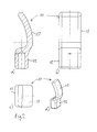
- FIG. 2a A longitudinal section through the front applicator part 11 is shown.
- a hollow receptacle is shown on the device-facing (proximal) side, which can serve for connection to the rest of the applicator, but does not play a significant role here.
- proximal proximal
- the flat-curved mold 13 starts from the pedestal with an inner radius of curvature of 5 mm, which gradually increases to the top of the flat-curved mold 13 up to 40 mm, the point itself being rounded with a radius of 2.5 mm is. This tip is tilted by 40 ° with respect to the impact direction.
- the radius of curvature on the outside of the flat-curved mold 13 is about 45 mm and the in Fig. 2a on average recognizable material thickness 5 mm. In the Fig. 2b visible width, however, is 20 mm over the entire area of the flat-curved mold 13, with only the corners are rounded.
- Fig. 2c shows a plan view, so a view in the direction of impact
- Fig. 2d a perspective view, wherein the concave side facing the rear left and the convex forward right. It can be seen that the tip lies in an area about 5 mm on both sides about the longitudinal axis (in the direction of impact).
- FIGS. 1 . 2a and 2d show that the front part 11 of the applicator 9 exactly a curvature with a concave side surface (in FIG. 2a to the left) and a convex (to the right), wherein the FIG. 2a also shows that in the local section plane the centers of curvature of the concavity and convexity are laterally adjacent to the applicator 9 and 11, namely, to the left. Furthermore, it can be seen that the curvature decreases from a proximal to a distal region.
Landscapes
- Health & Medical Sciences (AREA)
- Life Sciences & Earth Sciences (AREA)
- Surgery (AREA)
- Public Health (AREA)
- Veterinary Medicine (AREA)
- Animal Behavior & Ethology (AREA)
- General Health & Medical Sciences (AREA)
- Engineering & Computer Science (AREA)
- Orthopedic Medicine & Surgery (AREA)
- Biomedical Technology (AREA)
- Molecular Biology (AREA)
- Medical Informatics (AREA)
- Nuclear Medicine, Radiotherapy & Molecular Imaging (AREA)
- Heart & Thoracic Surgery (AREA)
- Vascular Medicine (AREA)
- Epidemiology (AREA)
- Rehabilitation Therapy (AREA)
- Pain & Pain Management (AREA)
- Physical Education & Sports Medicine (AREA)
- Mechanical Engineering (AREA)
- Surgical Instruments (AREA)
- Percussion Or Vibration Massage (AREA)
Priority Applications (3)
| Application Number | Priority Date | Filing Date | Title |
|---|---|---|---|
| EP14186613.7A EP3000418B1 (fr) | 2014-09-26 | 2014-09-26 | Appareil à chocs mécaniques pour le traitement du corps humain ou animal |
| US14/865,847 US20160089297A1 (en) | 2014-09-26 | 2015-09-25 | Apparatus for treating the human or animal body with mechanical strokes |
| CN201510859495.8A CN105534568B (zh) | 2014-09-26 | 2015-09-28 | 利用机械冲击处置人或动物身体的设备 |
Applications Claiming Priority (1)
| Application Number | Priority Date | Filing Date | Title |
|---|---|---|---|
| EP14186613.7A EP3000418B1 (fr) | 2014-09-26 | 2014-09-26 | Appareil à chocs mécaniques pour le traitement du corps humain ou animal |
Publications (2)
| Publication Number | Publication Date |
|---|---|
| EP3000418A1 true EP3000418A1 (fr) | 2016-03-30 |
| EP3000418B1 EP3000418B1 (fr) | 2016-11-09 |
Family
ID=51619045
Family Applications (1)
| Application Number | Title | Priority Date | Filing Date |
|---|---|---|---|
| EP14186613.7A Active EP3000418B1 (fr) | 2014-09-26 | 2014-09-26 | Appareil à chocs mécaniques pour le traitement du corps humain ou animal |
Country Status (3)
| Country | Link |
|---|---|
| US (1) | US20160089297A1 (fr) |
| EP (1) | EP3000418B1 (fr) |
| CN (1) | CN105534568B (fr) |
Families Citing this family (5)
| Publication number | Priority date | Publication date | Assignee | Title |
|---|---|---|---|---|
| US11484724B2 (en) | 2015-09-30 | 2022-11-01 | Btl Medical Solutions A.S. | Methods and devices for tissue treatment using mechanical stimulation and electromagnetic field |
| US12220380B2 (en) | 2015-09-30 | 2025-02-11 | Btl Medical Solutions A.S. | Methods and devices for tissue treatment using mechanical stimulation and electromagnetic field |
| CN107811832A (zh) * | 2017-11-28 | 2018-03-20 | 广东美的安川服务机器人有限公司 | 冲击波治疗装置 |
| US11779514B2 (en) * | 2019-09-02 | 2023-10-10 | Moon Pool Llc | Personal use extracorporeal low intensity acoustic or shock wave mechanical tip and methods of use |
| US20210283000A1 (en) * | 2020-03-14 | 2021-09-16 | Kusha Karvandi | Apparatus and method for relieving tightness in the hip flexor muscles |
Citations (7)
| Publication number | Priority date | Publication date | Assignee | Title |
|---|---|---|---|---|
| DE19725477A1 (de) * | 1997-06-17 | 1998-12-24 | Ferton Holding | Medizinisches Instrument zur Behandlung von biologischem Gewebe |
| US20020082532A1 (en) * | 2000-12-26 | 2002-06-27 | Tucek Kevin B. | Chiropractic adjustor apparatus having housing configured for enhanced heat dissipation and symmetrical force-transmitting shaft support |
| US20030009116A1 (en) * | 2001-07-03 | 2003-01-09 | Luettgen Harold A. | Vibrating personal massager |
| DE202004011323U1 (de) | 2004-07-09 | 2005-09-22 | Storz Medical Ag | Instrument zum Applizieren von Vibrationen auf dem menschlichen Körper |
| US20060064864A1 (en) * | 2004-09-27 | 2006-03-30 | Ferton Holding S.A. | Device and method for removing tooth applications such as brackets |
| EP2095843A1 (fr) | 2008-02-29 | 2009-09-02 | Storz Medical Ag | Dispositif de traitement de substances corporelles biologiques à l'aide d'ondes de pression mécaniques |
| US20110054367A1 (en) | 2004-07-09 | 2011-03-03 | Manfred Schulz | Instrument For Applying Vibrations To The Human Body |
Family Cites Families (12)
| Publication number | Priority date | Publication date | Assignee | Title |
|---|---|---|---|---|
| US2134133A (en) * | 1936-06-05 | 1938-10-25 | Joseph N Landau | Massage device |
| US5239985A (en) * | 1987-04-28 | 1993-08-31 | Medicuba | Electrode to destroy renal stones |
| CN1062650A (zh) * | 1990-12-29 | 1992-07-15 | 中国科学院电工研究所 | 体外冲击波碎石机放电电机 |
| US5885301A (en) * | 1993-03-26 | 1999-03-23 | Orthosonics, Ltd. | Tool bit for use in ultrasonic removal of plastics embedment of an osteal prostheses |
| US6010467A (en) * | 1997-08-22 | 2000-01-04 | William Arthur Smith | Back trigger-point instrument |
| US6856199B2 (en) * | 2000-10-10 | 2005-02-15 | California Institute Of Technology | Reconfigurable distributed active transformers |
| GB0116676D0 (en) * | 2001-07-07 | 2001-08-29 | Eaton Corp | Synchronizer |
| WO2010110823A1 (fr) * | 2009-03-27 | 2010-09-30 | Bing Innovations, Llc | Appareil et méthode de diminution de la douleur durant des procédures de ponction cutanée |
| CN1329007C (zh) * | 2004-12-28 | 2007-08-01 | 王华林 | 弹道碎石机用三通真空阀气路控制系统 |
| KR20140105744A (ko) * | 2011-11-10 | 2014-09-02 | 호메이욘 에이치. 자데흐 | 압전 골 수술용 개선된 수술 팁 |
| US9474682B2 (en) * | 2012-09-05 | 2016-10-25 | Star Generation Limited Taiwan Branch | Light guide type pain reliever |
| CN105407855A (zh) * | 2013-06-04 | 2016-03-16 | 西格玛仪器控股有限责任公司 | 诊断性和治疗性处理装置以及利用这种装置的相关系统和方法 |
-
2014
- 2014-09-26 EP EP14186613.7A patent/EP3000418B1/fr active Active
-
2015
- 2015-09-25 US US14/865,847 patent/US20160089297A1/en not_active Abandoned
- 2015-09-28 CN CN201510859495.8A patent/CN105534568B/zh active Active
Patent Citations (8)
| Publication number | Priority date | Publication date | Assignee | Title |
|---|---|---|---|---|
| DE19725477A1 (de) * | 1997-06-17 | 1998-12-24 | Ferton Holding | Medizinisches Instrument zur Behandlung von biologischem Gewebe |
| DE19725477C2 (de) | 1997-06-17 | 1999-10-21 | Ferton Holding | Medizinisches Instrument zur Behandlung von biologischem Gewebe |
| US20020082532A1 (en) * | 2000-12-26 | 2002-06-27 | Tucek Kevin B. | Chiropractic adjustor apparatus having housing configured for enhanced heat dissipation and symmetrical force-transmitting shaft support |
| US20030009116A1 (en) * | 2001-07-03 | 2003-01-09 | Luettgen Harold A. | Vibrating personal massager |
| DE202004011323U1 (de) | 2004-07-09 | 2005-09-22 | Storz Medical Ag | Instrument zum Applizieren von Vibrationen auf dem menschlichen Körper |
| US20110054367A1 (en) | 2004-07-09 | 2011-03-03 | Manfred Schulz | Instrument For Applying Vibrations To The Human Body |
| US20060064864A1 (en) * | 2004-09-27 | 2006-03-30 | Ferton Holding S.A. | Device and method for removing tooth applications such as brackets |
| EP2095843A1 (fr) | 2008-02-29 | 2009-09-02 | Storz Medical Ag | Dispositif de traitement de substances corporelles biologiques à l'aide d'ondes de pression mécaniques |
Also Published As
| Publication number | Publication date |
|---|---|
| US20160089297A1 (en) | 2016-03-31 |
| EP3000418B1 (fr) | 2016-11-09 |
| CN105534568A (zh) | 2016-05-04 |
| CN105534568B (zh) | 2019-09-03 |
Similar Documents
| Publication | Publication Date | Title |
|---|---|---|
| EP3388003B1 (fr) | Appareil d'onde de pression | |
| EP3000418B1 (fr) | Appareil à chocs mécaniques pour le traitement du corps humain ou animal | |
| DE69030262T2 (de) | Chirurgisches instrument mit wandler für die eingangsleistung | |
| DE202015005257U1 (de) | Gerät zur Behandlung des menschlichen oder tierischen Körpers mit mechanischen Stößen | |
| EP2996585B1 (fr) | Instrument chirurgical | |
| EP2213273A1 (fr) | Réglage des paramètres d'un appareil de traitement des ondes de pression | |
| EP2529679B1 (fr) | Manchon d'amortissement du bruit à mettre en place sur un appareil à ondes de pression | |
| DE102010050337A1 (de) | Vorrichtung zum Schneiden und Absaugen von Gewebe | |
| DE3542667A1 (de) | Vorrichtung zur entfernung von koerpersteinen | |
| DE102015103750A1 (de) | Spritze mit einem ersten und zweiten Spritzenzylinder | |
| DE69936509T2 (de) | Stossgedämpftes biopsie gerät | |
| EP3124004B1 (fr) | Appareil de traitement du corps humain ou animal a l'aide de chocs mécaniques | |
| DE202014007693U1 (de) | Gerät zur Behandlung des menschlichen oder tierischen Körpers mit mechanischen Stößen | |
| DE202014007692U1 (de) | Gerät zur Behandlung des menschlichen oder tierischen Körpers mit mechanischen Stößen | |
| EP3624709A1 (fr) | Dispositif d'élimination des selles dures | |
| CH704384A2 (de) | Chirurgisches Schneidinstrument. | |
| EP3000419B1 (fr) | Appareil à chocs mécaniques pour le traitement du corps humain ou animal | |
| DE202014010463U1 (de) | Gerät zur Behandlung des menschlichen oder tierischen Körpers mit mechanischen Stößen | |
| DE202007007922U1 (de) | Medizinisches Gerät zur Behandlung des menschlichen oder tierischen Körpers mit mechanischen Druck- oder Stoßwellen | |
| EP3852699A2 (fr) | Instrument d'opération intraoculaire | |
| EP3173036A1 (fr) | Dispositif destine au retrait d'os{j}ou de tissu conjonctif, en particulier destine a supprimer la compression sur la moelle epiniere en cas de stenose spinale | |
| EP3518800B1 (fr) | Outil à percussion pour l'usinage d'os lors d'opérations de la hanche | |
| DE102019206871B4 (de) | Vorrichtung zum Schneiden und Absaugen von Gewebe aus dem menschlichen oder tierischen Auge | |
| DE202014010461U1 (de) | Gerät zur Behandlung des menschlichen oder tierischen Körpers mit mechanischen Stößen | |
| DE202017001951U1 (de) | Druckwellengerät |
Legal Events
| Date | Code | Title | Description |
|---|---|---|---|
| PUAI | Public reference made under article 153(3) epc to a published international application that has entered the european phase |
Free format text: ORIGINAL CODE: 0009012 |
|
| 17P | Request for examination filed |
Effective date: 20160121 |
|
| AK | Designated contracting states |
Kind code of ref document: A1 Designated state(s): AL AT BE BG CH CY CZ DE DK EE ES FI FR GB GR HR HU IE IS IT LI LT LU LV MC MK MT NL NO PL PT RO RS SE SI SK SM TR |
|
| AX | Request for extension of the european patent |
Extension state: BA ME |
|
| GRAP | Despatch of communication of intention to grant a patent |
Free format text: ORIGINAL CODE: EPIDOSNIGR1 |
|
| INTG | Intention to grant announced |
Effective date: 20160614 |
|
| GRAS | Grant fee paid |
Free format text: ORIGINAL CODE: EPIDOSNIGR3 |
|
| GRAA | (expected) grant |
Free format text: ORIGINAL CODE: 0009210 |
|
| AK | Designated contracting states |
Kind code of ref document: B1 Designated state(s): AL AT BE BG CH CY CZ DE DK EE ES FI FR GB GR HR HU IE IS IT LI LT LU LV MC MK MT NL NO PL PT RO RS SE SI SK SM TR |
|
| REG | Reference to a national code |
Ref country code: GB Ref legal event code: FG4D Free format text: NOT ENGLISH |
|
| REG | Reference to a national code |
Ref country code: AT Ref legal event code: REF Ref document number: 843142 Country of ref document: AT Kind code of ref document: T Effective date: 20161115 Ref country code: CH Ref legal event code: EP |
|
| REG | Reference to a national code |
Ref country code: IE Ref legal event code: FG4D Free format text: LANGUAGE OF EP DOCUMENT: GERMAN |
|
| REG | Reference to a national code |
Ref country code: DE Ref legal event code: R096 Ref document number: 502014001915 Country of ref document: DE |
|
| PG25 | Lapsed in a contracting state [announced via postgrant information from national office to epo] |
Ref country code: LV Free format text: LAPSE BECAUSE OF FAILURE TO SUBMIT A TRANSLATION OF THE DESCRIPTION OR TO PAY THE FEE WITHIN THE PRESCRIBED TIME-LIMIT Effective date: 20161109 |
|
| REG | Reference to a national code |
Ref country code: LT Ref legal event code: MG4D |
|
| REG | Reference to a national code |
Ref country code: NL Ref legal event code: MP Effective date: 20161109 |
|
| PG25 | Lapsed in a contracting state [announced via postgrant information from national office to epo] |
Ref country code: NO Free format text: LAPSE BECAUSE OF FAILURE TO SUBMIT A TRANSLATION OF THE DESCRIPTION OR TO PAY THE FEE WITHIN THE PRESCRIBED TIME-LIMIT Effective date: 20170209 Ref country code: GR Free format text: LAPSE BECAUSE OF FAILURE TO SUBMIT A TRANSLATION OF THE DESCRIPTION OR TO PAY THE FEE WITHIN THE PRESCRIBED TIME-LIMIT Effective date: 20170210 Ref country code: NL Free format text: LAPSE BECAUSE OF FAILURE TO SUBMIT A TRANSLATION OF THE DESCRIPTION OR TO PAY THE FEE WITHIN THE PRESCRIBED TIME-LIMIT Effective date: 20161109 Ref country code: SE Free format text: LAPSE BECAUSE OF FAILURE TO SUBMIT A TRANSLATION OF THE DESCRIPTION OR TO PAY THE FEE WITHIN THE PRESCRIBED TIME-LIMIT Effective date: 20161109 Ref country code: LT Free format text: LAPSE BECAUSE OF FAILURE TO SUBMIT A TRANSLATION OF THE DESCRIPTION OR TO PAY THE FEE WITHIN THE PRESCRIBED TIME-LIMIT Effective date: 20161109 |
|
| PG25 | Lapsed in a contracting state [announced via postgrant information from national office to epo] |
Ref country code: ES Free format text: LAPSE BECAUSE OF FAILURE TO SUBMIT A TRANSLATION OF THE DESCRIPTION OR TO PAY THE FEE WITHIN THE PRESCRIBED TIME-LIMIT Effective date: 20161109 Ref country code: HR Free format text: LAPSE BECAUSE OF FAILURE TO SUBMIT A TRANSLATION OF THE DESCRIPTION OR TO PAY THE FEE WITHIN THE PRESCRIBED TIME-LIMIT Effective date: 20161109 Ref country code: IS Free format text: LAPSE BECAUSE OF FAILURE TO SUBMIT A TRANSLATION OF THE DESCRIPTION OR TO PAY THE FEE WITHIN THE PRESCRIBED TIME-LIMIT Effective date: 20170309 Ref country code: RS Free format text: LAPSE BECAUSE OF FAILURE TO SUBMIT A TRANSLATION OF THE DESCRIPTION OR TO PAY THE FEE WITHIN THE PRESCRIBED TIME-LIMIT Effective date: 20161109 Ref country code: FI Free format text: LAPSE BECAUSE OF FAILURE TO SUBMIT A TRANSLATION OF THE DESCRIPTION OR TO PAY THE FEE WITHIN THE PRESCRIBED TIME-LIMIT Effective date: 20161109 Ref country code: PT Free format text: LAPSE BECAUSE OF FAILURE TO SUBMIT A TRANSLATION OF THE DESCRIPTION OR TO PAY THE FEE WITHIN THE PRESCRIBED TIME-LIMIT Effective date: 20170309 Ref country code: PL Free format text: LAPSE BECAUSE OF FAILURE TO SUBMIT A TRANSLATION OF THE DESCRIPTION OR TO PAY THE FEE WITHIN THE PRESCRIBED TIME-LIMIT Effective date: 20161109 |
|
| PG25 | Lapsed in a contracting state [announced via postgrant information from national office to epo] |
Ref country code: RO Free format text: LAPSE BECAUSE OF FAILURE TO SUBMIT A TRANSLATION OF THE DESCRIPTION OR TO PAY THE FEE WITHIN THE PRESCRIBED TIME-LIMIT Effective date: 20161109 Ref country code: CZ Free format text: LAPSE BECAUSE OF FAILURE TO SUBMIT A TRANSLATION OF THE DESCRIPTION OR TO PAY THE FEE WITHIN THE PRESCRIBED TIME-LIMIT Effective date: 20161109 Ref country code: EE Free format text: LAPSE BECAUSE OF FAILURE TO SUBMIT A TRANSLATION OF THE DESCRIPTION OR TO PAY THE FEE WITHIN THE PRESCRIBED TIME-LIMIT Effective date: 20161109 Ref country code: DK Free format text: LAPSE BECAUSE OF FAILURE TO SUBMIT A TRANSLATION OF THE DESCRIPTION OR TO PAY THE FEE WITHIN THE PRESCRIBED TIME-LIMIT Effective date: 20161109 Ref country code: SK Free format text: LAPSE BECAUSE OF FAILURE TO SUBMIT A TRANSLATION OF THE DESCRIPTION OR TO PAY THE FEE WITHIN THE PRESCRIBED TIME-LIMIT Effective date: 20161109 |
|
| REG | Reference to a national code |
Ref country code: DE Ref legal event code: R097 Ref document number: 502014001915 Country of ref document: DE |
|
| PG25 | Lapsed in a contracting state [announced via postgrant information from national office to epo] |
Ref country code: SM Free format text: LAPSE BECAUSE OF FAILURE TO SUBMIT A TRANSLATION OF THE DESCRIPTION OR TO PAY THE FEE WITHIN THE PRESCRIBED TIME-LIMIT Effective date: 20161109 Ref country code: BG Free format text: LAPSE BECAUSE OF FAILURE TO SUBMIT A TRANSLATION OF THE DESCRIPTION OR TO PAY THE FEE WITHIN THE PRESCRIBED TIME-LIMIT Effective date: 20170209 |
|
| PLBE | No opposition filed within time limit |
Free format text: ORIGINAL CODE: 0009261 |
|
| STAA | Information on the status of an ep patent application or granted ep patent |
Free format text: STATUS: NO OPPOSITION FILED WITHIN TIME LIMIT |
|
| REG | Reference to a national code |
Ref country code: FR Ref legal event code: PLFP Year of fee payment: 4 |
|
| 26N | No opposition filed |
Effective date: 20170810 |
|
| PG25 | Lapsed in a contracting state [announced via postgrant information from national office to epo] |
Ref country code: SI Free format text: LAPSE BECAUSE OF FAILURE TO SUBMIT A TRANSLATION OF THE DESCRIPTION OR TO PAY THE FEE WITHIN THE PRESCRIBED TIME-LIMIT Effective date: 20161109 |
|
| REG | Reference to a national code |
Ref country code: CH Ref legal event code: PL |
|
| PG25 | Lapsed in a contracting state [announced via postgrant information from national office to epo] |
Ref country code: MC Free format text: LAPSE BECAUSE OF FAILURE TO SUBMIT A TRANSLATION OF THE DESCRIPTION OR TO PAY THE FEE WITHIN THE PRESCRIBED TIME-LIMIT Effective date: 20161109 |
|
| REG | Reference to a national code |
Ref country code: IE Ref legal event code: MM4A |
|
| REG | Reference to a national code |
Ref country code: BE Ref legal event code: MM Effective date: 20170930 |
|
| PG25 | Lapsed in a contracting state [announced via postgrant information from national office to epo] |
Ref country code: LU Free format text: LAPSE BECAUSE OF NON-PAYMENT OF DUE FEES Effective date: 20170926 |
|
| PG25 | Lapsed in a contracting state [announced via postgrant information from national office to epo] |
Ref country code: LI Free format text: LAPSE BECAUSE OF NON-PAYMENT OF DUE FEES Effective date: 20170930 Ref country code: IE Free format text: LAPSE BECAUSE OF NON-PAYMENT OF DUE FEES Effective date: 20170926 Ref country code: CH Free format text: LAPSE BECAUSE OF NON-PAYMENT OF DUE FEES Effective date: 20170930 |
|
| PG25 | Lapsed in a contracting state [announced via postgrant information from national office to epo] |
Ref country code: BE Free format text: LAPSE BECAUSE OF NON-PAYMENT OF DUE FEES Effective date: 20170930 |
|
| REG | Reference to a national code |
Ref country code: FR Ref legal event code: PLFP Year of fee payment: 5 |
|
| PG25 | Lapsed in a contracting state [announced via postgrant information from national office to epo] |
Ref country code: MT Free format text: LAPSE BECAUSE OF FAILURE TO SUBMIT A TRANSLATION OF THE DESCRIPTION OR TO PAY THE FEE WITHIN THE PRESCRIBED TIME-LIMIT Effective date: 20161109 |
|
| PG25 | Lapsed in a contracting state [announced via postgrant information from national office to epo] |
Ref country code: HU Free format text: LAPSE BECAUSE OF FAILURE TO SUBMIT A TRANSLATION OF THE DESCRIPTION OR TO PAY THE FEE WITHIN THE PRESCRIBED TIME-LIMIT; INVALID AB INITIO Effective date: 20140926 |
|
| PG25 | Lapsed in a contracting state [announced via postgrant information from national office to epo] |
Ref country code: CY Free format text: LAPSE BECAUSE OF FAILURE TO SUBMIT A TRANSLATION OF THE DESCRIPTION OR TO PAY THE FEE WITHIN THE PRESCRIBED TIME-LIMIT Effective date: 20161109 |
|
| PG25 | Lapsed in a contracting state [announced via postgrant information from national office to epo] |
Ref country code: MK Free format text: LAPSE BECAUSE OF FAILURE TO SUBMIT A TRANSLATION OF THE DESCRIPTION OR TO PAY THE FEE WITHIN THE PRESCRIBED TIME-LIMIT Effective date: 20161109 |
|
| PG25 | Lapsed in a contracting state [announced via postgrant information from national office to epo] |
Ref country code: TR Free format text: LAPSE BECAUSE OF FAILURE TO SUBMIT A TRANSLATION OF THE DESCRIPTION OR TO PAY THE FEE WITHIN THE PRESCRIBED TIME-LIMIT Effective date: 20161109 |
|
| PG25 | Lapsed in a contracting state [announced via postgrant information from national office to epo] |
Ref country code: AL Free format text: LAPSE BECAUSE OF FAILURE TO SUBMIT A TRANSLATION OF THE DESCRIPTION OR TO PAY THE FEE WITHIN THE PRESCRIBED TIME-LIMIT Effective date: 20161109 |
|
| REG | Reference to a national code |
Ref country code: AT Ref legal event code: MM01 Ref document number: 843142 Country of ref document: AT Kind code of ref document: T Effective date: 20190926 |
|
| PG25 | Lapsed in a contracting state [announced via postgrant information from national office to epo] |
Ref country code: AT Free format text: LAPSE BECAUSE OF NON-PAYMENT OF DUE FEES Effective date: 20190926 |
|
| P01 | Opt-out of the competence of the unified patent court (upc) registered |
Effective date: 20230504 |
|
| REG | Reference to a national code |
Ref country code: DE Ref legal event code: R082 Ref document number: 502014001915 Country of ref document: DE Representative=s name: SZYNKA SMORODIN PATENTANWAELTE PARTNERSCHAFT M, DE |
|
| PGFP | Annual fee paid to national office [announced via postgrant information from national office to epo] |
Ref country code: DE Payment date: 20250919 Year of fee payment: 12 |
|
| PGFP | Annual fee paid to national office [announced via postgrant information from national office to epo] |
Ref country code: IT Payment date: 20250924 Year of fee payment: 12 |
|
| PGFP | Annual fee paid to national office [announced via postgrant information from national office to epo] |
Ref country code: GB Payment date: 20250918 Year of fee payment: 12 |
|
| PGFP | Annual fee paid to national office [announced via postgrant information from national office to epo] |
Ref country code: FR Payment date: 20250922 Year of fee payment: 12 |