EP3124004B1 - Appareil de traitement du corps humain ou animal a l'aide de chocs mécaniques - Google Patents
Appareil de traitement du corps humain ou animal a l'aide de chocs mécaniques Download PDFInfo
- Publication number
- EP3124004B1 EP3124004B1 EP15178506.0A EP15178506A EP3124004B1 EP 3124004 B1 EP3124004 B1 EP 3124004B1 EP 15178506 A EP15178506 A EP 15178506A EP 3124004 B1 EP3124004 B1 EP 3124004B1
- Authority
- EP
- European Patent Office
- Prior art keywords
- applicator
- rotation
- rotatable
- impact
- axis
- Prior art date
- Legal status (The legal status is an assumption and is not a legal conclusion. Google has not performed a legal analysis and makes no representation as to the accuracy of the status listed.)
- Active
Links
Images

Classifications
-
- A—HUMAN NECESSITIES
- A61—MEDICAL OR VETERINARY SCIENCE; HYGIENE
- A61H—PHYSICAL THERAPY APPARATUS, e.g. DEVICES FOR LOCATING OR STIMULATING REFLEX POINTS IN THE BODY; ARTIFICIAL RESPIRATION; MASSAGE; BATHING DEVICES FOR SPECIAL THERAPEUTIC OR HYGIENIC PURPOSES OR SPECIFIC PARTS OF THE BODY
- A61H23/00—Percussion or vibration massage, e.g. using supersonic vibration; Suction-vibration massage; Massage with moving diaphragms
- A61H23/008—Percussion or vibration massage, e.g. using supersonic vibration; Suction-vibration massage; Massage with moving diaphragms using shock waves
-
- A—HUMAN NECESSITIES
- A61—MEDICAL OR VETERINARY SCIENCE; HYGIENE
- A61H—PHYSICAL THERAPY APPARATUS, e.g. DEVICES FOR LOCATING OR STIMULATING REFLEX POINTS IN THE BODY; ARTIFICIAL RESPIRATION; MASSAGE; BATHING DEVICES FOR SPECIAL THERAPEUTIC OR HYGIENIC PURPOSES OR SPECIFIC PARTS OF THE BODY
- A61H15/00—Massage by means of rollers, balls, e.g. inflatable, chains, or roller chains
- A61H15/0078—Massage by means of rollers, balls, e.g. inflatable, chains, or roller chains power-driven
- A61H15/0085—Massage by means of rollers, balls, e.g. inflatable, chains, or roller chains power-driven hand-held
-
- A—HUMAN NECESSITIES
- A61—MEDICAL OR VETERINARY SCIENCE; HYGIENE
- A61H—PHYSICAL THERAPY APPARATUS, e.g. DEVICES FOR LOCATING OR STIMULATING REFLEX POINTS IN THE BODY; ARTIFICIAL RESPIRATION; MASSAGE; BATHING DEVICES FOR SPECIAL THERAPEUTIC OR HYGIENIC PURPOSES OR SPECIFIC PARTS OF THE BODY
- A61H23/00—Percussion or vibration massage, e.g. using supersonic vibration; Suction-vibration massage; Massage with moving diaphragms
- A61H23/04—Percussion or vibration massage, e.g. using supersonic vibration; Suction-vibration massage; Massage with moving diaphragms with hydraulic or pneumatic drive
-
- A—HUMAN NECESSITIES
- A61—MEDICAL OR VETERINARY SCIENCE; HYGIENE
- A61B—DIAGNOSIS; SURGERY; IDENTIFICATION
- A61B17/00—Surgical instruments, devices or methods
- A61B17/22—Implements for squeezing-off ulcers or the like on inner organs of the body; Implements for scraping-out cavities of body organs, e.g. bones; for invasive removal or destruction of calculus using mechanical vibrations; for removing obstructions in blood vessels, not otherwise provided for
- A61B17/225—Implements for squeezing-off ulcers or the like on inner organs of the body; Implements for scraping-out cavities of body organs, e.g. bones; for invasive removal or destruction of calculus using mechanical vibrations; for removing obstructions in blood vessels, not otherwise provided for for extracorporeal shock wave lithotripsy [ESWL], e.g. by using ultrasonic waves
- A61B17/2251—Implements for squeezing-off ulcers or the like on inner organs of the body; Implements for scraping-out cavities of body organs, e.g. bones; for invasive removal or destruction of calculus using mechanical vibrations; for removing obstructions in blood vessels, not otherwise provided for for extracorporeal shock wave lithotripsy [ESWL], e.g. by using ultrasonic waves characterised by coupling elements between the apparatus, e.g. shock wave apparatus or locating means, and the patient, e.g. details of bags, pressure control of bag on patient
-
- A—HUMAN NECESSITIES
- A61—MEDICAL OR VETERINARY SCIENCE; HYGIENE
- A61B—DIAGNOSIS; SURGERY; IDENTIFICATION
- A61B17/00—Surgical instruments, devices or methods
- A61B2017/00535—Surgical instruments, devices or methods pneumatically or hydraulically operated
- A61B2017/00544—Surgical instruments, devices or methods pneumatically or hydraulically operated pneumatically
-
- A—HUMAN NECESSITIES
- A61—MEDICAL OR VETERINARY SCIENCE; HYGIENE
- A61H—PHYSICAL THERAPY APPARATUS, e.g. DEVICES FOR LOCATING OR STIMULATING REFLEX POINTS IN THE BODY; ARTIFICIAL RESPIRATION; MASSAGE; BATHING DEVICES FOR SPECIAL THERAPEUTIC OR HYGIENIC PURPOSES OR SPECIFIC PARTS OF THE BODY
- A61H15/00—Massage by means of rollers, balls, e.g. inflatable, chains, or roller chains
- A61H2015/0007—Massage by means of rollers, balls, e.g. inflatable, chains, or roller chains with balls or rollers rotating about their own axis
- A61H2015/0014—Massage by means of rollers, balls, e.g. inflatable, chains, or roller chains with balls or rollers rotating about their own axis cylinder-like, i.e. rollers
-
- A—HUMAN NECESSITIES
- A61—MEDICAL OR VETERINARY SCIENCE; HYGIENE
- A61H—PHYSICAL THERAPY APPARATUS, e.g. DEVICES FOR LOCATING OR STIMULATING REFLEX POINTS IN THE BODY; ARTIFICIAL RESPIRATION; MASSAGE; BATHING DEVICES FOR SPECIAL THERAPEUTIC OR HYGIENIC PURPOSES OR SPECIFIC PARTS OF THE BODY
- A61H15/00—Massage by means of rollers, balls, e.g. inflatable, chains, or roller chains
- A61H2015/0007—Massage by means of rollers, balls, e.g. inflatable, chains, or roller chains with balls or rollers rotating about their own axis
- A61H2015/0028—Massage by means of rollers, balls, e.g. inflatable, chains, or roller chains with balls or rollers rotating about their own axis disc-like, i.e. diameter substantially greater than width
-
- A—HUMAN NECESSITIES
- A61—MEDICAL OR VETERINARY SCIENCE; HYGIENE
- A61H—PHYSICAL THERAPY APPARATUS, e.g. DEVICES FOR LOCATING OR STIMULATING REFLEX POINTS IN THE BODY; ARTIFICIAL RESPIRATION; MASSAGE; BATHING DEVICES FOR SPECIAL THERAPEUTIC OR HYGIENIC PURPOSES OR SPECIFIC PARTS OF THE BODY
- A61H23/00—Percussion or vibration massage, e.g. using supersonic vibration; Suction-vibration massage; Massage with moving diaphragms
- A61H2023/002—Percussion or vibration massage, e.g. using supersonic vibration; Suction-vibration massage; Massage with moving diaphragms having a percussion element combined with a passive spacer element for bearing against the skin
-
- A—HUMAN NECESSITIES
- A61—MEDICAL OR VETERINARY SCIENCE; HYGIENE
- A61H—PHYSICAL THERAPY APPARATUS, e.g. DEVICES FOR LOCATING OR STIMULATING REFLEX POINTS IN THE BODY; ARTIFICIAL RESPIRATION; MASSAGE; BATHING DEVICES FOR SPECIAL THERAPEUTIC OR HYGIENIC PURPOSES OR SPECIFIC PARTS OF THE BODY
- A61H2201/00—Characteristics of apparatus not provided for in the preceding codes
- A61H2201/01—Constructive details
- A61H2201/0119—Support for the device
- A61H2201/0153—Support for the device hand-held
-
- A—HUMAN NECESSITIES
- A61—MEDICAL OR VETERINARY SCIENCE; HYGIENE
- A61H—PHYSICAL THERAPY APPARATUS, e.g. DEVICES FOR LOCATING OR STIMULATING REFLEX POINTS IN THE BODY; ARTIFICIAL RESPIRATION; MASSAGE; BATHING DEVICES FOR SPECIAL THERAPEUTIC OR HYGIENIC PURPOSES OR SPECIFIC PARTS OF THE BODY
- A61H2201/00—Characteristics of apparatus not provided for in the preceding codes
- A61H2201/16—Physical interface with patient
- A61H2201/1657—Movement of interface, i.e. force application means
- A61H2201/1671—Movement of interface, i.e. force application means rotational
-
- A—HUMAN NECESSITIES
- A61—MEDICAL OR VETERINARY SCIENCE; HYGIENE
- A61H—PHYSICAL THERAPY APPARATUS, e.g. DEVICES FOR LOCATING OR STIMULATING REFLEX POINTS IN THE BODY; ARTIFICIAL RESPIRATION; MASSAGE; BATHING DEVICES FOR SPECIAL THERAPEUTIC OR HYGIENIC PURPOSES OR SPECIFIC PARTS OF THE BODY
- A61H2201/00—Characteristics of apparatus not provided for in the preceding codes
- A61H2201/16—Physical interface with patient
- A61H2201/1683—Surface of interface
- A61H2201/1685—Surface of interface interchangeable
Definitions
- the present invention relates to an apparatus for treating the human or animal body by striking the body surface.
- the following describes the body of a patient who is preferably human.
- the DE 197 25 477 C describes, for example, such a device in which a pressure wave is triggered by the collision of a pneumatically accelerated impact part or projectile with an initially stationary impact body or applicator, which pressure wave can be coupled into the patient's body such that an applicator front surface is at the time of the collision Patient's body is placed.
- This type of device is derived in its history of lithotripsy devices, in which such pressure waves z. B. can be transferred to a kidney stone or the like via a long rod-shaped probe on the front surface of the applicator in order to disintegrate it.
- the focus in the display is in any case on the pressure wave generated by the collision, which should more or less resemble an actual shock wave, as used by classic, usually focusing lithotripsy devices such.
- Such pressure waves can have rising edges with a width in the range of a few ⁇ s and an amplitude in the low double-digit MPa range (eg 2 ⁇ s and 15 MPa measured 1 cm in front of the front surface).
- the cited document emphasizes that the physically inevitable macroscopic movement of the center of gravity of the applicator should be kept as small as possible because it is considered to be disruptive.
- a device is described which is similar in terms of its technical structure, but in which, among other things, the elastic suspension of the applicator in the housing is designed for larger movements of the center of gravity of the applicator (“strokes”).
- strokes the center of gravity of the applicator
- the therapeutic effect can also, or mainly, be seen in the actual macroscopic shocks (i.e. as a result of the stroke), which also depends on the indication.
- the present invention is generally directed to devices of this type, both with regard to the application of pressure waves and with regard to the application of "macroscopic impacts" of the applicator to the body surface.
- the object of the invention is to develop such a device with regard to further possible uses on the surface of the patient's body.
- a rotatable applicator part is provided. So there is a pivot bearing, in particular a shaft bearing with an axle pin but z. B. also a ball bearing (ball guided in pan) or a more complex bearing such. B. a gimbal. Via this bearing, the rotatable applicator part can be rotated relative to the rest of the device about at least one axis of rotation, this axis of rotation not being parallel, ie angled, to the direction of the impacts to be carried out by the device. The axis of rotation is preferably perpendicular to the direction of impact.
- the rotatable applicator part should be accessible in such a way that the device can be placed on the body in the corresponding manner. In other words, the rotatable applicator part should be exposed.
- An arrangement at the distal end of a is preferred corresponding handpiece, which is supplied at the other (proximal) end via a line from a base device.
- tissue sections under the skin can be massaged in parallel and / or pushed to a certain extent in front of the device, whereby they are simultaneously subjected to the impacts and (in a measure that varies from case to case) pressure waves.
- the conventionally known devices with fixed and more or less flat front surfaces of the applicators are relatively unsuitable for this because they can only be held on the skin surface with the device in a more or less vertical position relative to the body surface and are difficult to move in this position.
- the device according to the invention can be rolled over the surface and thus moved easily and gently, even when a certain contact pressure is exerted.
- the mechanism for generating the bumps of the applicator is conceivable in a wide variety of configurations, in particular also by direct application of the applicator by means of an electromagnetic mechanism or a pressure fluid pulse.
- an accelerated projectile for collision with the applicator which is already known from the cited documents, is preferred, with which relatively violent and (in the sense of the applicator speed) rapid impacts can be realized and the simultaneous or even main use of pressure waves is possible.
- the projectile in turn, can also be accelerated in various ways, in particular also electromagnetically, with a pneumatic action on the projectile being preferred according to the cited documents.
- the term "applicator” does not necessarily mean a one-piece part, apart from the rotatability. It is conceivable and, depending on the application, also preferred that the projectile e.g. B. strikes a first part that transmits the shock and / or the pressure wave to a second applicator part, which in turn is in contact with the patient's skin. In the prior art there is occasionally talk of an intermediate piece between the applicator and the projectile; this is then referred to as a multi-part applicator, the two applicator parts being able to be firmly connected, but not necessarily.
- a relatively large stroke of the applicator may well be desired, with the device in the present context preferably being designed in such a way that strokes over 1 mm can be reached, as already in FIG US 2011/0054367 A1 executed.
- the rotatable applicator part is preferably rotationally symmetrical with respect to the axis of rotation as an axis of symmetry in order to be able to roll particularly well.
- This rotational symmetry affects the rough shape, i.e. an envelope, so to speak, and does not conflict with superficial structures, such as grooves for massage purposes.
- the rotatable applicator part is also preferably mirror-symmetrical, specifically with respect to a plane of symmetry perpendicular to the axis of rotation. As a rule, this simplifies the application and, if the rotatable applicator part is suitably positioned relative to the rest of the device or handpiece, also permits appropriate use “from two sides”.
- the rotatable mounting is preferably carried out on both sides, in particular with a continuous bearing pin.
- Such a construction is simple and at the same time stable.
- a preferred shape is a barrel shape, that is to say an essentially cylindrical shape with a thickened central region, that is to say a convex outer profile in relation to a cutting plane containing the axis of rotation.
- a barrel shape that is to say an essentially cylindrical shape with a thickened central region, that is to say a convex outer profile in relation to a cutting plane containing the axis of rotation.
- Another preferred form has at least two regions which project radially with respect to the axis of rotation and are each designed for contact with the body surface.
- Such a shape can e.g. B. be inexpensive to be able to drive alongside on both sides next to an area that is not to be treated or to be spared, for example. To the right and left of a patient's spine.
- Previously known applicators were usually made of stainless steel.
- metals such as stainless steel, are also considered in principle.
- aluminum and titanium can be mentioned as metallic materials, both of which have a relatively low mass density and thus enable relatively light applicators. This can have the advantage of allowing greater acceleration and thus greater stroke deflection of the applicator for a given geometry, which can be desirable in the present case.
- Titan is also characterized by a particularly high mechanical strength, so it is particularly suitable for applications with comparatively high projectile speeds and / or projectile masses. Since titanium is also characterized by a particularly good physiological tolerance, it can also be an advantage as an applicator material, regardless of its resilience.
- the applicator is held in a releasable coupling, so that at least one distal applicator part (with the rotatable applicator part) can be pulled out of the device towards the front.
- proximal and distal are used here from the perspective of a user of the device; in other words, “distal” means a position facing the patient and “proximal” an opposite. In the same sense, the distal direction is referred to as "forward”, ie towards the patient.
- the inventors have found that the optimization of the applicator properties with regard to certain treatments, for example the change between an applicator according to the invention and a conventional or between different applicators with rotatable applicator parts, can advantageously be carried out on a case-by-case basis with the device remaining unchanged.
- an applicator can be constructed in several parts, with the removability primarily relating to a distal part. This distal part of the applicator can then be exchanged for other corresponding distal applicator parts, for example because the applicator part has a limited lifespan, because it is to be cleaned or sterilized or because another type of this distal applicator part (or the entire applicator) is to be used . In particular, it is possible to use differently shaped rotatable applicator parts, possibly also made of different materials, in their distal part.
- the exchange is very simple and quick, preferably completely without tools and also preferably without dismantling another device part, for example a screw-on cap in conventional devices of this type.
- the applicator was usually in one piece and a little thicker inside the device housing (perpendicular to the direction of impact) than a front opening. Removal was therefore possible, but only after the housing had been partially disassembled, namely by unscrewing a screw cap and not by loosening a coupling provided for changing the applicator.
- a preferred embodiment provides protection against rotation of the applicator in the device (not necessarily in the coupling).
- the coupling itself can, for example, provide security against rotation, or security against rotation can be created by inserting a correspondingly designed area of the applicator into a corresponding receptacle, particularly preferably by means of a polygonal pin on the applicator side and a suitable receptacle on the device side, for example by a hexagonal form fit .
- the anti-rotation device preferably also relates to at least one receptacle that is independent of the clutch itself (relating to the movement in the direction of impact) in order to improve the possibilities for absorbing force.
- at least one receptacle that is independent of the clutch itself (relating to the movement in the direction of impact) in order to improve the possibilities for absorbing force.
- the coupling can preferably also work with a form fit that does not necessarily have to match the form fit for the anti-rotation device.
- a clamping sleeve can be provided, which is displaceable (preferably in the direction of impact) and thereby presses at least one form-locking element into a corresponding receptacle on the applicator or releases it when it is released.
- a housing part of the device can be displaceable against a spring force and can have or also move the clamping sleeve.
- a ball can be considered as a positive-locking element, at least two balls preferably being provided. The balls or other positive locking elements can be acted upon by an inclined surface on the inside of the clamping sleeve.
- Figure 1 shows a longitudinal section through a front housing part of a device according to the invention with an applicator coupling.
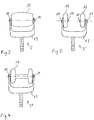
- FIGS. 2-4 show variants of the applicator according to the invention.
- a pneumatically operated pressure wave device on which the exemplary embodiment is based is well known, for which reference can be made to the prior art cited at the beginning. It has a base station with a pneumatic supply, an outgoing supply line and at the end of the supply line a mobile handpiece that can be handled by hand, which is referred to here as the device.
- the pneumatic supply is connected via the line and a corresponding switching valve to an acceleration tube, the left end of which is shown in the figure and numbered 1 in the figure.
- the pneumatic connection is located at the right end of the same tube 1, not shown, and in the tube 1, a projectile, not shown and filling the cross-section of the tube, can be moved, which can impact the right end face of a proximal applicator part 2 at the end of its movement distance.
- This proximal applicator part 2 has a largely conventional shape in comparison to the prior art and is supported with a radially enlarged flange and its distal shoulder side on an elastomer tube piece 3 which is deformable in the event of collisions and a movement of the proximal applicator part 2 can allow in the range over a millimeter. It is also responsible for the reset and decouples the blows from the device housing.
- this proximal applicator part 2 ends in a cylindrical pin which passes through a guide sleeve 4 and protrudes slightly beyond it on the distal side.
- this pin In conventional devices, the distal end face of this pin would be the contact surface of the applicator with the patient and the guide sleeve 4 in a (or as) unscrewable cap. You would have to remove the cap and do a partial disassembly before you can remove the applicator (in this case the proximal applicator part 2).
- the figure further shows that the left end face of the proximal applicator part 2 is in contact with the right end face of a distal applicator part 5.
- This distal applicator part 5 is based on the Figures 2-4 discussed in more detail. It is guided in a receptacle 6, namely positively, for. B hexagonal, and thus secured against rotation relative to this receiving piece 6.
- the receptacle 6, for its part must be held in the other housing in such a way that it is secured against rotation, for which purpose corresponding end faces pointing to the right in the figure or outwardly facing jacket surfaces can be coated in a friction-enhancing form or surface-structured.
- appropriate material combinations can be used, for example stainless steel on the applicator side and bronze, high-strength plastic (for example PEEK) or ceramic on the receiving side.
- the figure also shows that openings for form-locking balls 7 are provided in the receptacle 6 (above and below in the figure), which engage inward in corresponding outer grooves on the distal applicator part 5. These grooves are longer than necessary to the right in the figure, so that the entire applicator 5 and 6 can move to the left in one impact.
- the positive connection between the balls 7 and the associated grooves prevents the distal applicator part from falling out or shooting out of the housing. Rather, the distal applicator part can, for example, simply be pushed back into its drawn original position simply by being pressed onto the patient after an impact.
- a clamping sleeve 8 Radially outside the balls 7, a clamping sleeve 8 can be seen, which has an inner inclined surface at its left end. If this clamping sleeve 8 is moved to the right out of the position shown, the balls 7 can give way radially outwards and the distal applicator part 5 can simply be pulled out of the housing to the left. This displacement of the clamping sleeve 8 is ensured by manual (to the right) pushing in of an externally accessible housing part 9, a helical spring 10 pressing against it or ensuring the return movement, and this displaceable housing part 9 being displaceable in a further part 11 of the housing and by an O -Ring is guided. This part 11 encompasses and also holds the receiving piece 6 already mentioned.
- the balls 7 are not themselves subjected to force in the radial direction, but are displaced when the user pulls out the distal applicator part 5. Since there are only two (or in other cases, for example, three, four or six) balls for which separate grooves are provided, they also help to prevent rotation; However, the described polygonal positive-locking design of parts 5a on the outside and 6 on the inside is essential for securing against rotation.
- a projectile impact pushes the entire applicator to the left, resulting in a corresponding impact movement of the not shown distal end of the applicator (far left) against the patient's body, with the coupling of an actual pressure wave occurring in parallel, but in many cases is not essential at all.
- the pressure wave is generated in the proximal applicator part 2 and transmitted into the body via this and the distal applicator part 5.
- the proximal applicator part 2 automatically returns to the right as a result of the force exerted by the elastomer tube piece 3; for the distal applicator part 5, this follows from the pressure application on the patient's body.
- the distal applicator part 5 If the distal applicator part 5 is to be changed, the user pushes the displaceable housing part 9 to the right and thus also the clamping sleeve 4, so that the balls 7 can reach radially outwards. Incidentally, the openings in the receiving piece 6 for the balls 7 are too narrow radially on the inside, so that the balls cannot fall out.
- the housing part 9 When inserting another corresponding distal applicator part, the housing part 9 must be pushed to the right again in order to be able to displace the balls outwards. When the distal applicator part 5 is fully inserted, the housing part 9 can be released and the coupling locked.
- the Figures 2-4 show the configuration of the applicator or specifically the distal applicator part 5 in further details.
- the respective, here hexagonal rod for receiving in the receiving piece 6 with the grooves on the outside for the positive locking balls 7 can be seen.
- This rod leads to a fork-like widening 13, which in all three variants of the Figures 2-4 is identical and in their direction of impact (in the Figures 2-4 up and in Figure 1 ends or fork tines pointing to the left) have supports for bearing pins.
- FIG. 2 there is a continuous bearing pin defining the dash-dotted axis of rotation, the larger flattened ends 14 of which can be seen;
- Figure 4 there are two bearing pins with also flattened ends 14, one bearing pin per fork arm.
- Rotatable applicator parts namely a continuous convex barrel-shaped rotatable applicator part 15 in, are held on the bearing pins Figure 2 , two wheel-like applicator parts 16 in. each provided with a convex outer surface Figure 3 and a dumbbell-like rotatable applicator part 17 in Figure 4 , which is similar to the two applicator parts 16 Figure 3 , but is designed with a radially much smaller connection.
- the rotatability reduces the stress on the skin and facilitates the work of the therapist. It is also possible (but not mandatory) to hold the handpiece at an angle to the body surface (e.g. inclined about the respective axis of rotation so that the rotatable applicator part rolls in front of the handpiece), for example with an angle of rotation between 30% and 60%.
- a therapist can search for so-called trigger points along the body surface and carry out treatments with the combined effect of the pressure waves described, the actual impacts of the device and the massage effect.
- the front applicator parts can be used according to the Figures 2-4 interchange with each other, e.g. B. to with the examples from the Figures 3 and 4 to work along the spine so that the protruding areas of the rotatable applicator parts 16 and 17 roll on both sides of the spine.
- the parts can be made according to the Figures 2-4 can also be exchanged for conventional or differently shaped applicator parts.
- the fork and the hexagonal locating pin are made of metal, e.g. B. stainless steel or aluminum, which also applies to the bearing pins.
- the rotatable applicator parts 15-17 can consist of the materials mentioned above, for example also of plastic.
Landscapes
- Health & Medical Sciences (AREA)
- Epidemiology (AREA)
- Pain & Pain Management (AREA)
- Physical Education & Sports Medicine (AREA)
- Rehabilitation Therapy (AREA)
- Life Sciences & Earth Sciences (AREA)
- Animal Behavior & Ethology (AREA)
- General Health & Medical Sciences (AREA)
- Public Health (AREA)
- Veterinary Medicine (AREA)
- Surgical Instruments (AREA)
- Percussion Or Vibration Massage (AREA)
Claims (12)
- Appareil de traitement du corps humain ou animal, comportant:- un applicateur (2, 5, 5', 5") destiné à être appliqué par voie externe sur le corps,- un boîtier (9, 11, 12) dans lequel est retenu l'applicateur (2, 5, 5', 5"), et- un mécanisme permettant la production d'impacts par l'applicateur (2, 5, 5', 5") relativement au boîtier (9, 11, 12) selon une direction d'impact de manière que les impacts puissent être couplés dans le corps lors de l'application;ledit applicateur (2, 5, 5', 5") présentant un palier tournant (14) retenant en rotation une partie rotative (15, 16, 17) de l'applicateur (2, 5, 5', 5") destinée à être disposée sur le corps à traiter, et
une rotation de la partie d'applicateur rotative (15, 16, 17) étant possible sur un axe de rotation qui est à un certain angle par rapport à la direction d'impact,
caractérisé en ce que le mécanisme de production d'impacts présente un projectile et un dispositif pneumatique permettant d'accélérer le projectile de telle manière que le projectile frappe l'applicateur (2, 5, 5', 5") pour ainsi produire l'impact,
ledit applicateur (2, 5, 5', 5") étant retenu immobile en rotation dans l'appareil par complémentarité de forme, en ce qui concerne des rotations sur un axe parallèle à la direction d'impact. - Appareil selon la revendication 1, dans lequel l'axe de rotation est perpendiculaire à la direction d'impact.
- Appareil selon la revendication 1 ou 2, dans lequel la partie d'applicateur rotative (15, 16, 17) est symétrique en rotation sur l'axe de rotation.
- Appareil selon l'une des revendications précédentes, dans lequel la partie d'applicateur rotative (15, 16, 17) est en symétrie spéculaire par rapport à un plan perpendiculaire à l'axe de rotation.
- Appareil selon l'une des revendications précédentes, dans lequel la partie d'applicateur rotative (15, 17) est retenue rotative sur deux côtés opposés, en étant notamment traversée par une tige axiale définissant l'axe de rotation.
- Appareil selon l'une des revendications précédentes, dans lequel la partie d'applicateur rotative (15, 16, 17) présente des bords arrondis, sur l'extérieur, dont le rayon de courbure est d'au moins 1 mm.
- Appareil selon la revendication 3, également en conjonction avec une des revendications 4 à 6, dans lequel la partie d'applicateur rotative (15) présente une forme de tonneau cylindrique à profil extérieur convexe dans un plan de coupe contenant l'axe de rotation.
- Appareil selon l'une des revendications 1 à 6, dans lequel la partie d'applicateur rotative (17) présente au moins deux zones faisant radialement saillie par rapport à l'axe de rotation et conçues pour venir au contact du corps à traiter.
- Appareil selon l'une des revendications précédentes, dans lequel l'applicateur (2, 5, 5', 5") se compose de métal, notamment d'aluminium ou de titane, de plastique, de céramique ou de bois, dans sa partie rotative (15, 16, 17) destinée à être appliquée.
- Appareil selon l'une des revendications précédentes, conçu pour une course d'impact dans la direction d'impact par rapport au boîtier (9, 11, 12) qui est d'au moins 1 mm.
- Appareil selon l'une des revendications précédentes, dans lequel l'applicateur (2, 5, 5', 5") est retenu dans le boîtier (9, 11, 12) dans un dispositif d'accouplement (7, 8, 9, 10), au moins une partie d'applicateur distale (5) présentant la partie d'applicateur rotative (15, 16, 17) pouvant être retirée du boîtier (9, 11, 12) dans la direction distale après que le dispositif d'accouplement (7, 8, 9, 10) a été débloqué.
- Appareil selon l'une des revendications précédentes, dans lequel l'applicateur (2, 5, 5', 5") se compose d'au moins deux pièces, une partie d'applicateur distale (5, 5', 5") pouvant être retirée après qu'un dispositif d'accouplement (7, 8, 9, 10) a été débloqué tandis qu'une partie d'applicateur proximale (2) demeure dans le boîtier, ladite partie d'applicateur proximale (2) transmettant l'impact à la partie d'applicateur distale (5, 5', 5").
Priority Applications (1)
| Application Number | Priority Date | Filing Date | Title |
|---|---|---|---|
| EP15178506.0A EP3124004B1 (fr) | 2015-07-27 | 2015-07-27 | Appareil de traitement du corps humain ou animal a l'aide de chocs mécaniques |
Applications Claiming Priority (1)
| Application Number | Priority Date | Filing Date | Title |
|---|---|---|---|
| EP15178506.0A EP3124004B1 (fr) | 2015-07-27 | 2015-07-27 | Appareil de traitement du corps humain ou animal a l'aide de chocs mécaniques |
Publications (2)
| Publication Number | Publication Date |
|---|---|
| EP3124004A1 EP3124004A1 (fr) | 2017-02-01 |
| EP3124004B1 true EP3124004B1 (fr) | 2020-03-18 |
Family
ID=53762014
Family Applications (1)
| Application Number | Title | Priority Date | Filing Date |
|---|---|---|---|
| EP15178506.0A Active EP3124004B1 (fr) | 2015-07-27 | 2015-07-27 | Appareil de traitement du corps humain ou animal a l'aide de chocs mécaniques |
Country Status (1)
| Country | Link |
|---|---|
| EP (1) | EP3124004B1 (fr) |
Families Citing this family (3)
| Publication number | Priority date | Publication date | Assignee | Title |
|---|---|---|---|---|
| US12220380B2 (en) | 2015-09-30 | 2025-02-11 | Btl Medical Solutions A.S. | Methods and devices for tissue treatment using mechanical stimulation and electromagnetic field |
| US11484724B2 (en) | 2015-09-30 | 2022-11-01 | Btl Medical Solutions A.S. | Methods and devices for tissue treatment using mechanical stimulation and electromagnetic field |
| EP3388003B1 (fr) * | 2017-04-12 | 2020-07-22 | Storz Medical Ag | Appareil d'onde de pression |
Citations (2)
| Publication number | Priority date | Publication date | Assignee | Title |
|---|---|---|---|---|
| EP2181730A1 (fr) * | 2008-10-31 | 2010-05-05 | Ferton Holding SA | Instrument destiné au traitement de tissus biologiques et procédé de production d'ondes de pression de type ondes de choc dans un tel instrument |
| DE202010007860U1 (de) * | 2010-06-11 | 2011-09-27 | Storz Medical Ag | Druckwellengerät mit pneumatischem Antrieb |
Family Cites Families (10)
| Publication number | Priority date | Publication date | Assignee | Title |
|---|---|---|---|---|
| DE589285C (de) * | 1930-03-22 | 1934-03-24 | Max Schneidinger | Vibrations- und Rollmassageapparat |
| DE29512015U1 (de) * | 1995-07-25 | 1995-09-14 | Dr. Frenkel GmbH Geräte mit natürlicher Wirkweise, 72514 Inzigkofen | Massageroller als Zusatzteil für ein Handmassagegerät |
| DE19725477C2 (de) | 1997-06-17 | 1999-10-21 | Ferton Holding | Medizinisches Instrument zur Behandlung von biologischem Gewebe |
| US20020107459A1 (en) * | 2001-02-05 | 2002-08-08 | Chang Horng Jiun | Massage device having eccentric vibrating mechanism |
| US6503211B2 (en) * | 2001-05-25 | 2003-01-07 | Bruce A. Frye | Pneumatic spinal and extremity manipulator |
| US6758826B2 (en) * | 2001-07-03 | 2004-07-06 | Water Pik, Inc. | Vibrating personal massager |
| DE202004011323U1 (de) | 2004-07-09 | 2005-09-22 | Storz Medical Ag | Instrument zum Applizieren von Vibrationen auf dem menschlichen Körper |
| US8500665B2 (en) | 2004-07-09 | 2013-08-06 | Storz Medical Ag | Instrument for applying vibrations to the human body |
| ES2355962T3 (es) | 2008-02-29 | 2011-04-01 | Storz Medical Ag | Dispositivo de tratamiento de sustancias corporales biológicas con ondas de presión mecánicas. |
| BE1020090A5 (fr) * | 2012-01-20 | 2013-04-02 | M D Concept | Appareil pour le traitement extracorporel par ondes de choc. |
-
2015
- 2015-07-27 EP EP15178506.0A patent/EP3124004B1/fr active Active
Patent Citations (2)
| Publication number | Priority date | Publication date | Assignee | Title |
|---|---|---|---|---|
| EP2181730A1 (fr) * | 2008-10-31 | 2010-05-05 | Ferton Holding SA | Instrument destiné au traitement de tissus biologiques et procédé de production d'ondes de pression de type ondes de choc dans un tel instrument |
| DE202010007860U1 (de) * | 2010-06-11 | 2011-09-27 | Storz Medical Ag | Druckwellengerät mit pneumatischem Antrieb |
Also Published As
| Publication number | Publication date |
|---|---|
| EP3124004A1 (fr) | 2017-02-01 |
Similar Documents
| Publication | Publication Date | Title |
|---|---|---|
| DE202015005257U1 (de) | Gerät zur Behandlung des menschlichen oder tierischen Körpers mit mechanischen Stößen | |
| EP3388003B1 (fr) | Appareil d'onde de pression | |
| EP3000420B1 (fr) | Appareil de traitement du corps humain ou animal a l'aide de chocs mecaniques | |
| EP2497432B1 (fr) | Outil d'insertion médical | |
| EP2996585B1 (fr) | Instrument chirurgical | |
| DE102012106336A1 (de) | Knochenschraube und Knochenfixierungssystem | |
| DE202011101571U1 (de) | Schalldämpfungshülse zum Aufsetzen auf ein Druckwellengerät | |
| EP1883361A1 (fr) | Outil a percussion, en particulier pour application chirurgicale | |
| EP0928602A2 (fr) | Outil pour cisaillement d'implants | |
| EP2086429B1 (fr) | Appareil médical manuel | |
| EP3124004A1 (fr) | Appareil de traitement du corps humain ou animal a l'aide de chocs mecaniques | |
| EP3000418B1 (fr) | Appareil à chocs mécaniques pour le traitement du corps humain ou animal | |
| EP1099900B1 (fr) | Support articulé | |
| DE102014113634A1 (de) | Modulares chirurgisches Instrument der Ein-Wege-Bauart | |
| EP3250133B1 (fr) | Instrument d'arbre pour buts chirurgicals | |
| DE202004001504U1 (de) | Vorrichtung zum Einspannen von Knochenfixationsmitteln | |
| EP1954203B1 (fr) | Instrument chirurgical de guidage | |
| DE19949385C2 (de) | Vorrichtung zum Knochenverdichten für zahnärztlichimplantologische Zwecke | |
| DE19948031C2 (de) | Chirurgisches Rohrschaftinstrument | |
| DE202014010958U1 (de) | Werkzeug zum Aufbringen kleiner Schlagimpulse | |
| DE102014107173A1 (de) | Werkzeug und Verfahren zum Aufbringen kleiner Schlagimpulse | |
| DE202014007692U1 (de) | Gerät zur Behandlung des menschlichen oder tierischen Körpers mit mechanischen Stößen | |
| EP3494912A1 (fr) | Dispositif de desserrage de vis, en particulier soudées à froid, en orthopédie ainsi que insert d'outil | |
| DE202017001951U1 (de) | Druckwellengerät | |
| EP3000419B1 (fr) | Appareil à chocs mécaniques pour le traitement du corps humain ou animal |
Legal Events
| Date | Code | Title | Description |
|---|---|---|---|
| PUAI | Public reference made under article 153(3) epc to a published international application that has entered the european phase |
Free format text: ORIGINAL CODE: 0009012 |
|
| STAA | Information on the status of an ep patent application or granted ep patent |
Free format text: STATUS: REQUEST FOR EXAMINATION WAS MADE |
|
| 17P | Request for examination filed |
Effective date: 20160415 |
|
| AK | Designated contracting states |
Kind code of ref document: A1 Designated state(s): AL AT BE BG CH CY CZ DE DK EE ES FI FR GB GR HR HU IE IS IT LI LT LU LV MC MK MT NL NO PL PT RO RS SE SI SK SM TR |
|
| AX | Request for extension of the european patent |
Extension state: BA ME |
|
| RBV | Designated contracting states (corrected) |
Designated state(s): AL AT BE BG CH CY CZ DE DK EE ES FI FR GB GR HR HU IE IS IT LI LT LU LV MC MK MT NL NO PL PT RO RS SE SI SK SM TR |
|
| STAA | Information on the status of an ep patent application or granted ep patent |
Free format text: STATUS: EXAMINATION IS IN PROGRESS |
|
| 17Q | First examination report despatched |
Effective date: 20171129 |
|
| GRAP | Despatch of communication of intention to grant a patent |
Free format text: ORIGINAL CODE: EPIDOSNIGR1 |
|
| STAA | Information on the status of an ep patent application or granted ep patent |
Free format text: STATUS: GRANT OF PATENT IS INTENDED |
|
| INTG | Intention to grant announced |
Effective date: 20191024 |
|
| GRAS | Grant fee paid |
Free format text: ORIGINAL CODE: EPIDOSNIGR3 |
|
| GRAA | (expected) grant |
Free format text: ORIGINAL CODE: 0009210 |
|
| STAA | Information on the status of an ep patent application or granted ep patent |
Free format text: STATUS: THE PATENT HAS BEEN GRANTED |
|
| AK | Designated contracting states |
Kind code of ref document: B1 Designated state(s): AL AT BE BG CH CY CZ DE DK EE ES FI FR GB GR HR HU IE IS IT LI LT LU LV MC MK MT NL NO PL PT RO RS SE SI SK SM TR |
|
| REG | Reference to a national code |
Ref country code: GB Ref legal event code: FG4D Free format text: NOT ENGLISH |
|
| REG | Reference to a national code |
Ref country code: DE Ref legal event code: R096 Ref document number: 502015012023 Country of ref document: DE |
|
| REG | Reference to a national code |
Ref country code: AT Ref legal event code: REF Ref document number: 1245075 Country of ref document: AT Kind code of ref document: T Effective date: 20200415 Ref country code: IE Ref legal event code: FG4D Free format text: LANGUAGE OF EP DOCUMENT: GERMAN |
|
| REG | Reference to a national code |
Ref country code: CH Ref legal event code: NV Representative=s name: TR-IP CONSULTING LLC, CH |
|
| PG25 | Lapsed in a contracting state [announced via postgrant information from national office to epo] |
Ref country code: NO Free format text: LAPSE BECAUSE OF FAILURE TO SUBMIT A TRANSLATION OF THE DESCRIPTION OR TO PAY THE FEE WITHIN THE PRESCRIBED TIME-LIMIT Effective date: 20200618 Ref country code: FI Free format text: LAPSE BECAUSE OF FAILURE TO SUBMIT A TRANSLATION OF THE DESCRIPTION OR TO PAY THE FEE WITHIN THE PRESCRIBED TIME-LIMIT Effective date: 20200318 Ref country code: RS Free format text: LAPSE BECAUSE OF FAILURE TO SUBMIT A TRANSLATION OF THE DESCRIPTION OR TO PAY THE FEE WITHIN THE PRESCRIBED TIME-LIMIT Effective date: 20200318 |
|
| REG | Reference to a national code |
Ref country code: NL Ref legal event code: MP Effective date: 20200318 |
|
| PG25 | Lapsed in a contracting state [announced via postgrant information from national office to epo] |
Ref country code: HR Free format text: LAPSE BECAUSE OF FAILURE TO SUBMIT A TRANSLATION OF THE DESCRIPTION OR TO PAY THE FEE WITHIN THE PRESCRIBED TIME-LIMIT Effective date: 20200318 Ref country code: GR Free format text: LAPSE BECAUSE OF FAILURE TO SUBMIT A TRANSLATION OF THE DESCRIPTION OR TO PAY THE FEE WITHIN THE PRESCRIBED TIME-LIMIT Effective date: 20200619 Ref country code: BG Free format text: LAPSE BECAUSE OF FAILURE TO SUBMIT A TRANSLATION OF THE DESCRIPTION OR TO PAY THE FEE WITHIN THE PRESCRIBED TIME-LIMIT Effective date: 20200618 Ref country code: LV Free format text: LAPSE BECAUSE OF FAILURE TO SUBMIT A TRANSLATION OF THE DESCRIPTION OR TO PAY THE FEE WITHIN THE PRESCRIBED TIME-LIMIT Effective date: 20200318 Ref country code: SE Free format text: LAPSE BECAUSE OF FAILURE TO SUBMIT A TRANSLATION OF THE DESCRIPTION OR TO PAY THE FEE WITHIN THE PRESCRIBED TIME-LIMIT Effective date: 20200318 |
|
| REG | Reference to a national code |
Ref country code: LT Ref legal event code: MG4D |
|
| PG25 | Lapsed in a contracting state [announced via postgrant information from national office to epo] |
Ref country code: NL Free format text: LAPSE BECAUSE OF FAILURE TO SUBMIT A TRANSLATION OF THE DESCRIPTION OR TO PAY THE FEE WITHIN THE PRESCRIBED TIME-LIMIT Effective date: 20200318 |
|
| PG25 | Lapsed in a contracting state [announced via postgrant information from national office to epo] |
Ref country code: PT Free format text: LAPSE BECAUSE OF FAILURE TO SUBMIT A TRANSLATION OF THE DESCRIPTION OR TO PAY THE FEE WITHIN THE PRESCRIBED TIME-LIMIT Effective date: 20200812 Ref country code: LT Free format text: LAPSE BECAUSE OF FAILURE TO SUBMIT A TRANSLATION OF THE DESCRIPTION OR TO PAY THE FEE WITHIN THE PRESCRIBED TIME-LIMIT Effective date: 20200318 Ref country code: EE Free format text: LAPSE BECAUSE OF FAILURE TO SUBMIT A TRANSLATION OF THE DESCRIPTION OR TO PAY THE FEE WITHIN THE PRESCRIBED TIME-LIMIT Effective date: 20200318 Ref country code: SM Free format text: LAPSE BECAUSE OF FAILURE TO SUBMIT A TRANSLATION OF THE DESCRIPTION OR TO PAY THE FEE WITHIN THE PRESCRIBED TIME-LIMIT Effective date: 20200318 Ref country code: RO Free format text: LAPSE BECAUSE OF FAILURE TO SUBMIT A TRANSLATION OF THE DESCRIPTION OR TO PAY THE FEE WITHIN THE PRESCRIBED TIME-LIMIT Effective date: 20200318 Ref country code: CZ Free format text: LAPSE BECAUSE OF FAILURE TO SUBMIT A TRANSLATION OF THE DESCRIPTION OR TO PAY THE FEE WITHIN THE PRESCRIBED TIME-LIMIT Effective date: 20200318 Ref country code: SK Free format text: LAPSE BECAUSE OF FAILURE TO SUBMIT A TRANSLATION OF THE DESCRIPTION OR TO PAY THE FEE WITHIN THE PRESCRIBED TIME-LIMIT Effective date: 20200318 Ref country code: IS Free format text: LAPSE BECAUSE OF FAILURE TO SUBMIT A TRANSLATION OF THE DESCRIPTION OR TO PAY THE FEE WITHIN THE PRESCRIBED TIME-LIMIT Effective date: 20200718 |
|
| PGFP | Annual fee paid to national office [announced via postgrant information from national office to epo] |
Ref country code: GB Payment date: 20200728 Year of fee payment: 6 Ref country code: DE Payment date: 20200723 Year of fee payment: 6 Ref country code: FR Payment date: 20200722 Year of fee payment: 6 |
|
| PGFP | Annual fee paid to national office [announced via postgrant information from national office to epo] |
Ref country code: IT Payment date: 20200731 Year of fee payment: 6 Ref country code: CH Payment date: 20200728 Year of fee payment: 6 |
|
| REG | Reference to a national code |
Ref country code: DE Ref legal event code: R097 Ref document number: 502015012023 Country of ref document: DE |
|
| PLBE | No opposition filed within time limit |
Free format text: ORIGINAL CODE: 0009261 |
|
| STAA | Information on the status of an ep patent application or granted ep patent |
Free format text: STATUS: NO OPPOSITION FILED WITHIN TIME LIMIT |
|
| PG25 | Lapsed in a contracting state [announced via postgrant information from national office to epo] |
Ref country code: ES Free format text: LAPSE BECAUSE OF FAILURE TO SUBMIT A TRANSLATION OF THE DESCRIPTION OR TO PAY THE FEE WITHIN THE PRESCRIBED TIME-LIMIT Effective date: 20200318 Ref country code: DK Free format text: LAPSE BECAUSE OF FAILURE TO SUBMIT A TRANSLATION OF THE DESCRIPTION OR TO PAY THE FEE WITHIN THE PRESCRIBED TIME-LIMIT Effective date: 20200318 |
|
| 26N | No opposition filed |
Effective date: 20201221 |
|
| PG25 | Lapsed in a contracting state [announced via postgrant information from national office to epo] |
Ref country code: MC Free format text: LAPSE BECAUSE OF FAILURE TO SUBMIT A TRANSLATION OF THE DESCRIPTION OR TO PAY THE FEE WITHIN THE PRESCRIBED TIME-LIMIT Effective date: 20200318 Ref country code: PL Free format text: LAPSE BECAUSE OF FAILURE TO SUBMIT A TRANSLATION OF THE DESCRIPTION OR TO PAY THE FEE WITHIN THE PRESCRIBED TIME-LIMIT Effective date: 20200318 |
|
| REG | Reference to a national code |
Ref country code: BE Ref legal event code: MM Effective date: 20200731 |
|
| PG25 | Lapsed in a contracting state [announced via postgrant information from national office to epo] |
Ref country code: LU Free format text: LAPSE BECAUSE OF NON-PAYMENT OF DUE FEES Effective date: 20200727 |
|
| PG25 | Lapsed in a contracting state [announced via postgrant information from national office to epo] |
Ref country code: BE Free format text: LAPSE BECAUSE OF NON-PAYMENT OF DUE FEES Effective date: 20200731 Ref country code: SI Free format text: LAPSE BECAUSE OF FAILURE TO SUBMIT A TRANSLATION OF THE DESCRIPTION OR TO PAY THE FEE WITHIN THE PRESCRIBED TIME-LIMIT Effective date: 20200318 |
|
| PG25 | Lapsed in a contracting state [announced via postgrant information from national office to epo] |
Ref country code: IE Free format text: LAPSE BECAUSE OF NON-PAYMENT OF DUE FEES Effective date: 20200727 |
|
| REG | Reference to a national code |
Ref country code: AT Ref legal event code: MM01 Ref document number: 1245075 Country of ref document: AT Kind code of ref document: T Effective date: 20200727 |
|
| PG25 | Lapsed in a contracting state [announced via postgrant information from national office to epo] |
Ref country code: AT Free format text: LAPSE BECAUSE OF NON-PAYMENT OF DUE FEES Effective date: 20200727 |
|
| REG | Reference to a national code |
Ref country code: DE Ref legal event code: R119 Ref document number: 502015012023 Country of ref document: DE |
|
| REG | Reference to a national code |
Ref country code: CH Ref legal event code: PL |
|
| GBPC | Gb: european patent ceased through non-payment of renewal fee |
Effective date: 20210727 |
|
| PG25 | Lapsed in a contracting state [announced via postgrant information from national office to epo] |
Ref country code: LI Free format text: LAPSE BECAUSE OF NON-PAYMENT OF DUE FEES Effective date: 20210731 Ref country code: GB Free format text: LAPSE BECAUSE OF NON-PAYMENT OF DUE FEES Effective date: 20210727 Ref country code: DE Free format text: LAPSE BECAUSE OF NON-PAYMENT OF DUE FEES Effective date: 20220201 Ref country code: CH Free format text: LAPSE BECAUSE OF NON-PAYMENT OF DUE FEES Effective date: 20210731 |
|
| PG25 | Lapsed in a contracting state [announced via postgrant information from national office to epo] |
Ref country code: TR Free format text: LAPSE BECAUSE OF FAILURE TO SUBMIT A TRANSLATION OF THE DESCRIPTION OR TO PAY THE FEE WITHIN THE PRESCRIBED TIME-LIMIT Effective date: 20200318 Ref country code: MT Free format text: LAPSE BECAUSE OF FAILURE TO SUBMIT A TRANSLATION OF THE DESCRIPTION OR TO PAY THE FEE WITHIN THE PRESCRIBED TIME-LIMIT Effective date: 20200318 Ref country code: FR Free format text: LAPSE BECAUSE OF NON-PAYMENT OF DUE FEES Effective date: 20210731 Ref country code: CY Free format text: LAPSE BECAUSE OF FAILURE TO SUBMIT A TRANSLATION OF THE DESCRIPTION OR TO PAY THE FEE WITHIN THE PRESCRIBED TIME-LIMIT Effective date: 20200318 |
|
| PG25 | Lapsed in a contracting state [announced via postgrant information from national office to epo] |
Ref country code: MK Free format text: LAPSE BECAUSE OF FAILURE TO SUBMIT A TRANSLATION OF THE DESCRIPTION OR TO PAY THE FEE WITHIN THE PRESCRIBED TIME-LIMIT Effective date: 20200318 Ref country code: AL Free format text: LAPSE BECAUSE OF FAILURE TO SUBMIT A TRANSLATION OF THE DESCRIPTION OR TO PAY THE FEE WITHIN THE PRESCRIBED TIME-LIMIT Effective date: 20200318 |
|
| PG25 | Lapsed in a contracting state [announced via postgrant information from national office to epo] |
Ref country code: IT Free format text: LAPSE BECAUSE OF NON-PAYMENT OF DUE FEES Effective date: 20210727 |
|
| REG | Reference to a national code |
Ref country code: CH Ref legal event code: R17 Free format text: ST27 STATUS EVENT CODE: U-0-0-R10-R17 (AS PROVIDED BY THE NATIONAL OFFICE) Effective date: 20251022 |