EP3000420B2 - Appareil de traitement du corps humain ou animal a l'aide de chocs mecaniques - Google Patents
Appareil de traitement du corps humain ou animal a l'aide de chocs mecaniques Download PDFInfo
- Publication number
- EP3000420B2 EP3000420B2 EP15020170.5A EP15020170A EP3000420B2 EP 3000420 B2 EP3000420 B2 EP 3000420B2 EP 15020170 A EP15020170 A EP 15020170A EP 3000420 B2 EP3000420 B2 EP 3000420B2
- Authority
- EP
- European Patent Office
- Prior art keywords
- applicator
- housing
- coupling
- form closure
- housing part
- Prior art date
- Legal status (The legal status is an assumption and is not a legal conclusion. Google has not performed a legal analysis and makes no representation as to the accuracy of the status listed.)
- Active
Links
Images


Classifications
-
- A—HUMAN NECESSITIES
- A61—MEDICAL OR VETERINARY SCIENCE; HYGIENE
- A61B—DIAGNOSIS; SURGERY; IDENTIFICATION
- A61B17/00—Surgical instruments, devices or methods
- A61B17/22—Implements for squeezing-off ulcers or the like on inner organs of the body; Implements for scraping-out cavities of body organs, e.g. bones; for invasive removal or destruction of calculus using mechanical vibrations; for removing obstructions in blood vessels, not otherwise provided for
- A61B17/22004—Implements for squeezing-off ulcers or the like on inner organs of the body; Implements for scraping-out cavities of body organs, e.g. bones; for invasive removal or destruction of calculus using mechanical vibrations; for removing obstructions in blood vessels, not otherwise provided for using mechanical vibrations, e.g. ultrasonic shock waves
-
- A—HUMAN NECESSITIES
- A61—MEDICAL OR VETERINARY SCIENCE; HYGIENE
- A61B—DIAGNOSIS; SURGERY; IDENTIFICATION
- A61B17/00—Surgical instruments, devices or methods
- A61B2017/0046—Surgical instruments, devices or methods with a releasable handle; with handle and operating part separable
- A61B2017/00473—Distal part, e.g. tip or head
-
- A—HUMAN NECESSITIES
- A61—MEDICAL OR VETERINARY SCIENCE; HYGIENE
- A61B—DIAGNOSIS; SURGERY; IDENTIFICATION
- A61B17/00—Surgical instruments, devices or methods
- A61B2017/00477—Coupling
Definitions
- DE 197 25 477 C describes, for example, such a device in which a pressure wave is triggered by the collision of a pneumatically accelerated impact part or projectile with an initially stationary impact body or applicator, which can be coupled into the patient's body by placing an applicator front surface on the patient's body at the time of the collision.
- the history of this type of device is derived from lithotripsy devices in which such pressure waves can be transmitted to a kidney stone or similar, for example via a long rod-shaped probe on the front surface of the applicator, in order to disintegrate it.
- an elastic element for absorbing impact movements can be provided on the distal side of the first applicator part, in particular an elastomer tube piece or an O-ring, which is also responsible for returning the applicator part to its original position.
- This elastic element is then not a hindrance during removal because the applicator is divided into at least two parts.
- the coupling for the applicator described so far can also be removed from the (remaining) device.
- it is part of a housing part, namely on a side of the device facing the body to be treated, which can accordingly be removed from the rest of the housing.
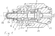
- the detachable connection provided for this purpose between this housing part and the rest of the housing can, for example, be a thread, as shown in the first embodiment.
- left-hand threads and/or threads with a special shape, e.g. round threads or trapezoidal threads, and/or multi-start threads are conceivable here. It can be particularly advantageous to use a very specific, somewhat unusual thread.
- the device also has an applicator cap (without coupling).
- an applicator cap (without coupling).
- This can then be used in exchange for the removable housing part, for example, to carry out treatments for which applicators that are difficult to mount with the coupling are suitable.
- the exemplary embodiment shows that the proximal applicator part mentioned above can be used after removing the removable housing part and the distal applicator part and then after applying a known applicator cap to the thread, namely with its distal end, i.e. the flat front surface.
- other applicators could of course also be used instead of the proximal applicator part and used in the known manner after screwing on the applicator cap.
- applicator caps without applicator coupling
- the removable housing part with the applicator coupling
- the pneumatic connection is located at the right end (not shown) of the same tube 1 and a projectile (not shown) filling the cross-section of the tube is movable in the tube 1 and can impact the right end face of a proximal applicator part 2 at the end of its travel path.
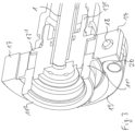
- Figure 2 shows a perspective view of a second embodiment, here without distal applicator part 5.
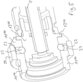
- the first embodiment in Figure 1 The connection, which is realized by the thread 14, which can be a left-hand thread or a thread of another type, is formed by a bayonet mechanism. Otherwise, the embodiments correspond, whereby some reference numerals have been replaced for clarification. Figure 1 are entered. However, the corresponding elements are not explained again.
Landscapes
- Health & Medical Sciences (AREA)
- Surgery (AREA)
- Engineering & Computer Science (AREA)
- Life Sciences & Earth Sciences (AREA)
- Biomedical Technology (AREA)
- Nuclear Medicine, Radiotherapy & Molecular Imaging (AREA)
- Vascular Medicine (AREA)
- Orthopedic Medicine & Surgery (AREA)
- Mechanical Engineering (AREA)
- Heart & Thoracic Surgery (AREA)
- Medical Informatics (AREA)
- Molecular Biology (AREA)
- Animal Behavior & Ethology (AREA)
- General Health & Medical Sciences (AREA)
- Public Health (AREA)
- Veterinary Medicine (AREA)
- Surgical Instruments (AREA)
Claims (15)
- Appareil pour le traitement du corps humain ou animal, comportant:- un applicateur (2, 5) destiné à une application sur ledit corps depuis l'extérieur,- un boîtier (9, 11-11"", 12) destiné à retenir l'applicateur (2, 5), et- un mécanisme (1) permettant à l'applicateur (2, 5) d'exercer des coups par rapport au boîtier (9, 11-11"", 12) dans une direction d'impact, de manière que les coups peuvent être répercutés dans le corps suite à ladite application,ledit applicateur (2, 5) étant retenu dans le boîtier (9, 11-11"", 12) dans un coupleur (7, 8, 9, 10),au moins une partie distale d'applicateur (5) pouvant, après desserrage du coupleur (7, 8, 9, 10), être dégagée vers l'avant hors du coupleur (7, 8, 9, 10) et du boîtier (9, 11-11"", 12) sans devoir démonter une autre partie du boîtier, etledit coupleur (7, 8, 9, 10) pouvant être desserré par déplacement d'une douille de blocage (8), conçue pour retenir l'applicateur (2, 5) sous l'effet d'au moins un élément à complémentarité de forme (7) sollicité vers l'intérieur, sur l'applicateur (2, 5), dans une direction perpendiculaire à la direction d'impact, et conçue pour le libérer en permettant un mouvement de retour de l'élément à complémentarité de forme (7),caractérisé en ce que l'au moins un élément à complémentarité de forme (7) rentre dans une rainure côté applicateur qui laisse de la place à l'élément à complémentarité de forme (7) pour un mouvement d'impact de l'applicateur (2, 5) vers l'avant.
- Appareil pour le traitement du corps humain ou animal, comportant:- un applicateur (2, 5) destiné à une application sur ledit corps depuis l'extérieur,- un boîtier (9, 11-11"", 12) destiné à retenir l'applicateur (2, 5), et- un mécanisme (1) permettant à l'applicateur (2, 5) d'exercer des coups par rapport au boîtier (9, 11-11"", 12) dans une direction d'impact, de manière que les coups peuvent être répercutés dans le corps suite à ladite application,ledit applicateur (2, 5) étant retenu dans le boîtier (9, 11-11"", 12) dans un coupleur (7, 8, 9, 10),au moins une partie distale d'applicateur (5) pouvant, après desserrage du coupleur (7, 8, 9, 10), être dégagée vers l'avant hors du coupleur (7, 8, 9, 10) et du boîtier (9, 11-11"", 12) sans devoir démonter une autre partie du boîtier, etledit applicateur (2, 5) se composant d'au moins deux parties, une partie distale d'applicateur (5) pouvant être dégagée après desserrage du coupleur (7, 8, 9, 10) et une partie proximale d'applicateur (2) demeurant dans le boîtier, la partie proximale d'applicateur (2) transmettant l'impact sur la partie distale d'applicateur (5),caractérisé en ce que le coupleur (7, 8, 9, 10) est prévu dans une partie (7-10, 11-11"", 12) du boîtier qui est tournée vers le corps à traiter, laquelle partie de boîtier (7-10, 11-11"", 12) peut être ôtée du reste du boîtier (13-13"") par desserrage d'un raccord mécanique (15-24) conjointement au coupleur (7, 8, 9, 10), etcaractérisé par un capuchon d'applicateur, comme partie de boîtier, qui est susceptible d'être fixé sur le reste du boîtier (13-13"") à la place de la partie de boîtier (7-10, 11-11"", 12) présentant le coupleur (7, 8, 9, 10), par le biais d'un raccord mécanique correspondant au raccord mécanique (15-24), et qui est conçu, dans cet état de fixation, pour amener la partie proximale d'applicateur (2), ou un applicateur installé à la place de cette dernière, à faire saillie vers l'extérieur dans la direction d'impact en traversant le capuchon d'applicateur et à venir en contact avec ledit corps à traiter.
- Appareil selon la revendication 1 ou 2, dans lequel le mécanisme (1) permettant d'exercer des coups présente un projectile et un dispositif (1) permettant une accélération du projectile de telle manière que le projectile frappe l'applicateur (2, 5) en produisant ainsi ledit coup, s'agissant de préférence d'un dispositif pneumatique d'accélération du projectile.
- Appareil selon l'une quelconque des revendications précédentes, dans lequel l'applicateur (2, 5) est retenu dans l'appareil par complémentarité de forme sans possibilité de rotation, plus précisément sans possibilité de rotation sur un axe de rotation parallèle à la direction d'impact, une goupille polygonale (5a) entrant dans la réalisation de la complémentarité de forme de préférence du côté applicateur, en s'étendant dans la direction d'impact et, de l'autre côté, un évidement (6) qui y est adapté.
- Appareil selon la revendication 2, facultativement en conjonction avec la revendication 3 ou 4, dans lequel le coupleur (7, 8, 9, 10) peut être desserré par déplacement d'une douille de blocage (8), conçue pour retenir l'applicateur (2, 5) sous l'effet d'au moins un élément à complémentarité de forme (7) sollicité vers l'intérieur, sur l'applicateur (2, 5), dans une direction perpendiculaire à la direction d'impact, et conçue pour le libérer en permettant un mouvement de retour de l'élément à complémentarité de forme (7).
- Appareil selon la revendication 5, dans lequel le coupleur (7, 8, 9, 10), en vue du desserrage, peut être manipulé par déplacement d'une partie (9) du boîtier de l'appareil contre une force de ressort, à savoir de préférence à l'encontre de la direction d'impact, et la partie de boîtier (9) déplace ou présente la douille de blocage (8), et la douille de blocage (8) présente de préférence des surfaces inclinées destinées à solliciter l'élément à complémentarité de forme, et dans lequel l'élément à complémentarité de forme (7) comprend de préférence au moins deux billes.
- Appareil selon les revendications 2 et 6, facultativement également en conjonction avec la revendication 3, 4 ou 5, dans lequel l'au moins un élément à complémentarité de forme (7) rentre dans une rainure côté applicateur qui laisse de la place à l'élément à complémentarité de forme (7) pour un mouvement d'impact de l'applicateur (2, 5) vers l'avant.
- Appareil selon la revendication 1, facultativement en conjonction avec l'une des revendications 3 à 7, dans lequel l'applicateur (2, 5) se compose d'au moins deux parties, une partie distale d'applicateur (5) pouvant être dégagée après desserrage du coupleur (7, 8, 9, 10) et une partie proximale d'applicateur (2) demeurant dans le boîtier, la partie proximale d'applicateur (2) transmettant l'impact sur la partie distale d'applicateur (5), en sachant que, de préférence, la partie proximale d'applicateur (2) repose, avant la production d'un impact, contre un élément élastique (3) situé entre cette partie proximale d'applicateur (2) et une autre partie (4) de l'appareil qui limite le mouvement d'impact de la partie proximale d'applicateur (2) et ramène cette dernière dans sa position d'origine.
- Appareil selon l'une quelconque des revendications précédentes, dans lequel le coupleur (7, 8, 9, 10) est prévu dans une partie (7-10, 11', 12) du boîtier tournée vers le corps à traiter, laquelle partie de boîtier (7-10, 11', 12) peut être ôtée du reste du boîtier (13') par desserrage d'un raccord à baïonnette (15, 16) conjointement au coupleur (7, 8, 9, 10).
- Appareil selon l'une quelconque des revendications 1 à 8, dans lequel le coupleur (7, 8, 9, 10) est prévu dans une partie (7-10, 11", 12) du boîtier (9, 11, 12) qui est tournée vers le corps à traiter, laquelle partie de boîtier (7-10, 11", 12) peut être ôtée du reste du boîtier (13") par desserrage d'un raccord à anneau de serrage (17-20) conjointement au coupleur (7, 8, 9, 10), ledit raccord à anneau de serrage (17-20) présentant un anneau de serrage (17-20) qui entoure une zone de chevauchement entre la partie de boîtier (7-10, 11", 12) et le reste du boîtier (13").
- Appareil selon la revendication 10, dans lequel l'anneau de serrage (17-20) peut être serré au moyen d'un levier excentrique (19).
- Appareil selon l'une quelconque des revendications 1 à 8, dans lequel le coupleur (7, 8, 9, 10) est prévu dans une partie (7-10, 11‴, 12) du boîtier qui est tournée vers le corps à traiter, laquelle partie de boîtier (7-10, 11‴, 12) peut être ôtée du reste du boîtier (13'") par desserrage d'un raccord à goupille de verrouillage (21) conjointement au coupleur (7, 8, 9, 10), ledit raccord à goupille de verrouillage (21) présentant au moins une et de préférence deux goupilles de verrouillage (21) mobiles de manière perpendiculaire par rapport à la direction d'impact et conçues pour produire un verrouillage par complémentarité de forme dans une zone de chevauchement entre la partie de boîtier (7-10, 11‴, 12) et le reste du boîtier (13'").
- Appareil selon l'une quelconque des revendications 1 à 8, dans lequel le coupleur (7, 8, 9, 10) est prévu dans une partie (7-10, 11"", 12) du boîtier qui est tournée vers le corps à traiter, laquelle partie de boîtier (7-10, 11"", 12) peut être ôtée du reste du boîtier (13"") par desserrage d'un raccord à complémentarité de forme (22-24) conjointement au coupleur (7, 8, 9, 10), le raccord à complémentarité de forme (22-24) présentant au moins une bille (22) comme élément à complémentarité de forme, laquelle est susceptible d'être mise en mouvement perpendiculairement à la direction d'impact du fait du mouvement d'une douille de manipulation (24) dans une zone de chevauchement de la partie de boîtier (7-10, 11"", 12) et du reste du boîtier (13ʺʺ) en produisant ainsi une complémentarité de forme établie et suspendue par la coopération entre la bille (22) et un évidement adapté.
- Appareil selon la revendication 13, dans lequel la douille de manipulation (24) est mobile dans un sens circonférentiel autour de la direction d'impact et présente, sur une face intérieure, un évidement permettant le mouvement de l'au au moins une bille (22).
- Appareil selon les revendications 1 et 8, dans lequel le coupleur (7, 8, 9, 10) est prévu dans une partie (7-10, 11-11"", 12) du boîtier tournée vers le corps à traiter, laquelle partie de boîtier (7-10, 11-11"", 12) peut être ôtée du reste du boîtier (13-13"") par desserrage d'un raccord mécanique (15-24) conjointement au coupleur (7, 8, 9, 10), ledit raccord mécanique (15-24) correspondant de préférence à l'une des revendications 10 à 14,
et comportant encore, comme partie de boîtier, un capuchon d'applicateur qui est susceptible d'être fixé sur le reste du boîtier (13-13"") à la place de la partie de boîtier (7-10, 11-11"", 12) présentant le coupleur (7, 8, 9, 10), par le biais d'un raccord mécanique correspondant au raccord mécanique (15-24), et qui est conçu, dans cet état de fixation, pour amener la partie proximale d'applicateur (2), ou un applicateur installé à la place de cette dernière, à faire saillie vers l'extérieur dans la direction d'impact en traversant le capuchon d'applicateur et à venir en contact avec ledit corps à traiter.
Applications Claiming Priority (1)
| Application Number | Priority Date | Filing Date | Title |
|---|---|---|---|
| DE202014007694 | 2014-09-26 |
Publications (3)
| Publication Number | Publication Date |
|---|---|
| EP3000420A1 EP3000420A1 (fr) | 2016-03-30 |
| EP3000420B1 EP3000420B1 (fr) | 2016-10-12 |
| EP3000420B2 true EP3000420B2 (fr) | 2024-06-26 |
Family
ID=54207282
Family Applications (1)
| Application Number | Title | Priority Date | Filing Date |
|---|---|---|---|
| EP15020170.5A Active EP3000420B2 (fr) | 2014-09-26 | 2015-09-23 | Appareil de traitement du corps humain ou animal a l'aide de chocs mecaniques |
Country Status (2)
| Country | Link |
|---|---|
| EP (1) | EP3000420B2 (fr) |
| DE (1) | DE202015006596U1 (fr) |
Families Citing this family (6)
| Publication number | Priority date | Publication date | Assignee | Title |
|---|---|---|---|---|
| US12220380B2 (en) | 2015-09-30 | 2025-02-11 | Btl Medical Solutions A.S. | Methods and devices for tissue treatment using mechanical stimulation and electromagnetic field |
| US11484724B2 (en) | 2015-09-30 | 2022-11-01 | Btl Medical Solutions A.S. | Methods and devices for tissue treatment using mechanical stimulation and electromagnetic field |
| DE102019128044A1 (de) * | 2019-10-17 | 2021-04-22 | Karl Storz Se & Co. Kg | Lithotripsievorrichtung |
| DE202021100954U1 (de) | 2021-02-25 | 2022-05-30 | Storz Medical Ag | Gerät zur Behandlung des menschlichen oder tierischen Körpers mit mechanischen Stößen |
| DE102021104566A1 (de) | 2021-02-25 | 2022-08-25 | Storz Medical Ag | Gerät zur Behandlung des menschlichen oder tierischen Körpers mit mechanischen Stößen |
| CN114391956A (zh) * | 2022-01-19 | 2022-04-26 | 北京罗森博特科技有限公司 | 快速安装锁紧装置 |
Citations (5)
| Publication number | Priority date | Publication date | Assignee | Title |
|---|---|---|---|---|
| DE2735563A1 (de) † | 1976-08-09 | 1978-02-16 | American Safety Equip | Chirurgisches geraet mit impulsmotor |
| DE3048293A1 (de) † | 1979-12-29 | 1981-10-15 | Mabuchi Motor Co.,Ltd., Tokyo | "schoenheitsbehandlungsvorrichtung" |
| DE19624446C1 (de) † | 1996-06-19 | 1998-03-26 | Ferton Holding | Chirurgisches Instrument zum mechanischen Entfernen von Knochenzement, sowie Verfahren zum Erzeugen von Stoßwellen |
| DE202010009890U1 (de) † | 2010-07-02 | 2010-10-21 | Meyer, Werner | Luftgepolsteter Zeltfußboden |
| US20120029393A1 (en) † | 2010-07-30 | 2012-02-02 | General Electric Company | Compact ultrasound transducer assembly and methods of making and using the same |
Family Cites Families (7)
| Publication number | Priority date | Publication date | Assignee | Title |
|---|---|---|---|---|
| US5735855A (en) | 1996-10-25 | 1998-04-07 | Bradley; Gary W. | Automatic impact device |
| DE19725477C2 (de) | 1997-06-17 | 1999-10-21 | Ferton Holding | Medizinisches Instrument zur Behandlung von biologischem Gewebe |
| US6213971B1 (en) | 1998-11-04 | 2001-04-10 | James Poole | Power assisted liposuction device |
| DE20317386U1 (de) | 2003-11-07 | 2005-01-13 | Storz Medical Ag | Vorrichtung zum Behandeln von Körpergewebe mit Druck- oder Stoßwellen |
| DE202004011323U1 (de) | 2004-07-09 | 2005-09-22 | Storz Medical Ag | Instrument zum Applizieren von Vibrationen auf dem menschlichen Körper |
| US8500665B2 (en) | 2004-07-09 | 2013-08-06 | Storz Medical Ag | Instrument for applying vibrations to the human body |
| DE202009004616U1 (de) | 2009-04-03 | 2010-08-19 | Storz Medical Ag | Vorrichtung zur Behandlung des menschlichen oder tierischen Körpers durch mechanische Druckwellen mit einem austauschbaren Prallkörper |
-
2015
- 2015-09-23 EP EP15020170.5A patent/EP3000420B2/fr active Active
- 2015-09-23 DE DE202015006596.1U patent/DE202015006596U1/de not_active Expired - Lifetime
Patent Citations (5)
| Publication number | Priority date | Publication date | Assignee | Title |
|---|---|---|---|---|
| DE2735563A1 (de) † | 1976-08-09 | 1978-02-16 | American Safety Equip | Chirurgisches geraet mit impulsmotor |
| DE3048293A1 (de) † | 1979-12-29 | 1981-10-15 | Mabuchi Motor Co.,Ltd., Tokyo | "schoenheitsbehandlungsvorrichtung" |
| DE19624446C1 (de) † | 1996-06-19 | 1998-03-26 | Ferton Holding | Chirurgisches Instrument zum mechanischen Entfernen von Knochenzement, sowie Verfahren zum Erzeugen von Stoßwellen |
| DE202010009890U1 (de) † | 2010-07-02 | 2010-10-21 | Meyer, Werner | Luftgepolsteter Zeltfußboden |
| US20120029393A1 (en) † | 2010-07-30 | 2012-02-02 | General Electric Company | Compact ultrasound transducer assembly and methods of making and using the same |
Also Published As
| Publication number | Publication date |
|---|---|
| EP3000420A1 (fr) | 2016-03-30 |
| DE202015006596U1 (de) | 2016-01-05 |
| EP3000420B1 (fr) | 2016-10-12 |
Similar Documents
| Publication | Publication Date | Title |
|---|---|---|
| EP3000420B1 (fr) | Appareil de traitement du corps humain ou animal a l'aide de chocs mecaniques | |
| DE10311455B3 (de) | Kupplung für ein chirurgisches Drehantriebs-Handstück | |
| DE102007052173B4 (de) | Handhabungswerkzeug für ein medizinisches Implantat | |
| EP3388003B1 (fr) | Appareil d'onde de pression | |
| DE202015005257U1 (de) | Gerät zur Behandlung des menschlichen oder tierischen Körpers mit mechanischen Stößen | |
| EP2846951B1 (fr) | Raccord à serrage rapide | |
| DE102010005706A1 (de) | Spannvorrichtung für chirurgische Elemente | |
| DE3640420A1 (de) | Selbstspannendes spannfutter | |
| EP0928602A2 (fr) | Outil pour cisaillement d'implants | |
| EP3124004B1 (fr) | Appareil de traitement du corps humain ou animal a l'aide de chocs mécaniques | |
| WO2015049037A1 (fr) | Tige d'endoscope | |
| EP3494912B1 (fr) | Dispositif de desserrage de vis, en particulier soudées à froid, en orthopédie | |
| DE102005016869A1 (de) | Medizinisches Handstück mit einer Spannzange | |
| EP2229110B1 (fr) | Dispositif rapporté pour dispositif chirurgical et dispositif chirurgical correspondant pour percer un os | |
| DE102013211368B4 (de) | Endoskopisches Schaftinstrument | |
| DE102022116372B4 (de) | Chirurgisches instrument und verfahren zu dessen zerlegung | |
| DE102011121989A1 (de) | Chirurgisches Instrument | |
| WO2011038845A1 (fr) | Dispositif pour usiner des éléments en forme de barre | |
| DE202017001951U1 (de) | Druckwellengerät | |
| DE2457713A1 (de) | Fraeskopf fuer medizinische zwecke | |
| DE102014114644A1 (de) | Medizinischer Schraubendreher, Adapter und Kanüle für den medizinischen Schraubendreher | |
| DE102016101822A1 (de) | Instrument zum Führen eines Stabs in eine Implantataufnahme | |
| DE102014116776A1 (de) | Knochenschraube und Knochenfixierungssystem | |
| DE3618620A1 (de) | Vorrichtung zum automatischen zufuehren und eindrehen von schrauben | |
| DE102014103345A1 (de) | Schlüssellose medizintechnische Werkzeugkupplung |
Legal Events
| Date | Code | Title | Description |
|---|---|---|---|
| PUAI | Public reference made under article 153(3) epc to a published international application that has entered the european phase |
Free format text: ORIGINAL CODE: 0009012 |
|
| AK | Designated contracting states |
Kind code of ref document: A1 Designated state(s): AL AT BE BG CH CY CZ DE DK EE ES FI FR GB GR HR HU IE IS IT LI LT LU LV MC MK MT NL NO PL PT RO RS SE SI SK SM TR |
|
| AX | Request for extension of the european patent |
Extension state: BA ME |
|
| 17P | Request for examination filed |
Effective date: 20160302 |
|
| GRAP | Despatch of communication of intention to grant a patent |
Free format text: ORIGINAL CODE: EPIDOSNIGR1 |
|
| INTG | Intention to grant announced |
Effective date: 20160615 |
|
| GRAS | Grant fee paid |
Free format text: ORIGINAL CODE: EPIDOSNIGR3 |
|
| GRAA | (expected) grant |
Free format text: ORIGINAL CODE: 0009210 |
|
| AK | Designated contracting states |
Kind code of ref document: B1 Designated state(s): AL AT BE BG CH CY CZ DE DK EE ES FI FR GB GR HR HU IE IS IT LI LT LU LV MC MK MT NL NO PL PT RO RS SE SI SK SM TR |
|
| RBV | Designated contracting states (corrected) |
Designated state(s): AL AT BE BG CH CY CZ DE DK EE ES FI FR GB GR HR HU IE IS IT LI LT LU LV MC MK MT NL NO PL PT RO RS SE SI SK SM TR |
|
| REG | Reference to a national code |
Ref country code: GB Ref legal event code: FG4D Free format text: NOT ENGLISH |
|
| REG | Reference to a national code |
Ref country code: CH Ref legal event code: EP |
|
| REG | Reference to a national code |
Ref country code: AT Ref legal event code: REF Ref document number: 835725 Country of ref document: AT Kind code of ref document: T Effective date: 20161015 |
|
| REG | Reference to a national code |
Ref country code: IE Ref legal event code: FG4D Free format text: LANGUAGE OF EP DOCUMENT: GERMAN |
|
| REG | Reference to a national code |
Ref country code: DE Ref legal event code: R096 Ref document number: 502015000216 Country of ref document: DE |
|
| REG | Reference to a national code |
Ref country code: LT Ref legal event code: MG4D |
|
| REG | Reference to a national code |
Ref country code: NL Ref legal event code: MP Effective date: 20161012 |
|
| PG25 | Lapsed in a contracting state [announced via postgrant information from national office to epo] |
Ref country code: LV Free format text: LAPSE BECAUSE OF FAILURE TO SUBMIT A TRANSLATION OF THE DESCRIPTION OR TO PAY THE FEE WITHIN THE PRESCRIBED TIME-LIMIT Effective date: 20161012 |
|
| PG25 | Lapsed in a contracting state [announced via postgrant information from national office to epo] |
Ref country code: NO Free format text: LAPSE BECAUSE OF FAILURE TO SUBMIT A TRANSLATION OF THE DESCRIPTION OR TO PAY THE FEE WITHIN THE PRESCRIBED TIME-LIMIT Effective date: 20170112 Ref country code: GR Free format text: LAPSE BECAUSE OF FAILURE TO SUBMIT A TRANSLATION OF THE DESCRIPTION OR TO PAY THE FEE WITHIN THE PRESCRIBED TIME-LIMIT Effective date: 20170113 Ref country code: LT Free format text: LAPSE BECAUSE OF FAILURE TO SUBMIT A TRANSLATION OF THE DESCRIPTION OR TO PAY THE FEE WITHIN THE PRESCRIBED TIME-LIMIT Effective date: 20161012 Ref country code: SE Free format text: LAPSE BECAUSE OF FAILURE TO SUBMIT A TRANSLATION OF THE DESCRIPTION OR TO PAY THE FEE WITHIN THE PRESCRIBED TIME-LIMIT Effective date: 20161012 |
|
| PG25 | Lapsed in a contracting state [announced via postgrant information from national office to epo] |
Ref country code: NL Free format text: LAPSE BECAUSE OF FAILURE TO SUBMIT A TRANSLATION OF THE DESCRIPTION OR TO PAY THE FEE WITHIN THE PRESCRIBED TIME-LIMIT Effective date: 20161012 Ref country code: FI Free format text: LAPSE BECAUSE OF FAILURE TO SUBMIT A TRANSLATION OF THE DESCRIPTION OR TO PAY THE FEE WITHIN THE PRESCRIBED TIME-LIMIT Effective date: 20161012 Ref country code: ES Free format text: LAPSE BECAUSE OF FAILURE TO SUBMIT A TRANSLATION OF THE DESCRIPTION OR TO PAY THE FEE WITHIN THE PRESCRIBED TIME-LIMIT Effective date: 20161012 Ref country code: PL Free format text: LAPSE BECAUSE OF FAILURE TO SUBMIT A TRANSLATION OF THE DESCRIPTION OR TO PAY THE FEE WITHIN THE PRESCRIBED TIME-LIMIT Effective date: 20161012 Ref country code: IS Free format text: LAPSE BECAUSE OF FAILURE TO SUBMIT A TRANSLATION OF THE DESCRIPTION OR TO PAY THE FEE WITHIN THE PRESCRIBED TIME-LIMIT Effective date: 20170212 Ref country code: PT Free format text: LAPSE BECAUSE OF FAILURE TO SUBMIT A TRANSLATION OF THE DESCRIPTION OR TO PAY THE FEE WITHIN THE PRESCRIBED TIME-LIMIT Effective date: 20170213 Ref country code: HR Free format text: LAPSE BECAUSE OF FAILURE TO SUBMIT A TRANSLATION OF THE DESCRIPTION OR TO PAY THE FEE WITHIN THE PRESCRIBED TIME-LIMIT Effective date: 20161012 Ref country code: RS Free format text: LAPSE BECAUSE OF FAILURE TO SUBMIT A TRANSLATION OF THE DESCRIPTION OR TO PAY THE FEE WITHIN THE PRESCRIBED TIME-LIMIT Effective date: 20161012 |
|
| REG | Reference to a national code |
Ref country code: DE Ref legal event code: R026 Ref document number: 502015000216 Country of ref document: DE |
|
| PLBI | Opposition filed |
Free format text: ORIGINAL CODE: 0009260 |
|
| PG25 | Lapsed in a contracting state [announced via postgrant information from national office to epo] |
Ref country code: RO Free format text: LAPSE BECAUSE OF FAILURE TO SUBMIT A TRANSLATION OF THE DESCRIPTION OR TO PAY THE FEE WITHIN THE PRESCRIBED TIME-LIMIT Effective date: 20161012 Ref country code: EE Free format text: LAPSE BECAUSE OF FAILURE TO SUBMIT A TRANSLATION OF THE DESCRIPTION OR TO PAY THE FEE WITHIN THE PRESCRIBED TIME-LIMIT Effective date: 20161012 Ref country code: CZ Free format text: LAPSE BECAUSE OF FAILURE TO SUBMIT A TRANSLATION OF THE DESCRIPTION OR TO PAY THE FEE WITHIN THE PRESCRIBED TIME-LIMIT Effective date: 20161012 Ref country code: DK Free format text: LAPSE BECAUSE OF FAILURE TO SUBMIT A TRANSLATION OF THE DESCRIPTION OR TO PAY THE FEE WITHIN THE PRESCRIBED TIME-LIMIT Effective date: 20161012 Ref country code: SK Free format text: LAPSE BECAUSE OF FAILURE TO SUBMIT A TRANSLATION OF THE DESCRIPTION OR TO PAY THE FEE WITHIN THE PRESCRIBED TIME-LIMIT Effective date: 20161012 |
|
| 26 | Opposition filed |
Opponent name: FERTON HOLDING SA Effective date: 20170712 |
|
| PLAX | Notice of opposition and request to file observation + time limit sent |
Free format text: ORIGINAL CODE: EPIDOSNOBS2 |
|
| PG25 | Lapsed in a contracting state [announced via postgrant information from national office to epo] |
Ref country code: SM Free format text: LAPSE BECAUSE OF FAILURE TO SUBMIT A TRANSLATION OF THE DESCRIPTION OR TO PAY THE FEE WITHIN THE PRESCRIBED TIME-LIMIT Effective date: 20161012 Ref country code: BG Free format text: LAPSE BECAUSE OF FAILURE TO SUBMIT A TRANSLATION OF THE DESCRIPTION OR TO PAY THE FEE WITHIN THE PRESCRIBED TIME-LIMIT Effective date: 20170112 |
|
| REG | Reference to a national code |
Ref country code: FR Ref legal event code: PLFP Year of fee payment: 3 |
|
| PG25 | Lapsed in a contracting state [announced via postgrant information from national office to epo] |
Ref country code: SI Free format text: LAPSE BECAUSE OF FAILURE TO SUBMIT A TRANSLATION OF THE DESCRIPTION OR TO PAY THE FEE WITHIN THE PRESCRIBED TIME-LIMIT Effective date: 20161012 |
|
| PLBB | Reply of patent proprietor to notice(s) of opposition received |
Free format text: ORIGINAL CODE: EPIDOSNOBS3 |
|
| PG25 | Lapsed in a contracting state [announced via postgrant information from national office to epo] |
Ref country code: MC Free format text: LAPSE BECAUSE OF FAILURE TO SUBMIT A TRANSLATION OF THE DESCRIPTION OR TO PAY THE FEE WITHIN THE PRESCRIBED TIME-LIMIT Effective date: 20161012 |
|
| REG | Reference to a national code |
Ref country code: IE Ref legal event code: MM4A |
|
| REG | Reference to a national code |
Ref country code: BE Ref legal event code: MM Effective date: 20170930 |
|
| PG25 | Lapsed in a contracting state [announced via postgrant information from national office to epo] |
Ref country code: LU Free format text: LAPSE BECAUSE OF NON-PAYMENT OF DUE FEES Effective date: 20170923 |
|
| PG25 | Lapsed in a contracting state [announced via postgrant information from national office to epo] |
Ref country code: IE Free format text: LAPSE BECAUSE OF NON-PAYMENT OF DUE FEES Effective date: 20170923 |
|
| PG25 | Lapsed in a contracting state [announced via postgrant information from national office to epo] |
Ref country code: BE Free format text: LAPSE BECAUSE OF NON-PAYMENT OF DUE FEES Effective date: 20170930 |
|
| REG | Reference to a national code |
Ref country code: FR Ref legal event code: PLFP Year of fee payment: 4 |
|
| PG25 | Lapsed in a contracting state [announced via postgrant information from national office to epo] |
Ref country code: MT Free format text: LAPSE BECAUSE OF FAILURE TO SUBMIT A TRANSLATION OF THE DESCRIPTION OR TO PAY THE FEE WITHIN THE PRESCRIBED TIME-LIMIT Effective date: 20161012 |
|
| PLAY | Examination report in opposition despatched + time limit |
Free format text: ORIGINAL CODE: EPIDOSNORE2 |
|
| PLBC | Reply to examination report in opposition received |
Free format text: ORIGINAL CODE: EPIDOSNORE3 |
|
| REG | Reference to a national code |
Ref country code: CH Ref legal event code: PL |
|
| PG25 | Lapsed in a contracting state [announced via postgrant information from national office to epo] |
Ref country code: HU Free format text: LAPSE BECAUSE OF FAILURE TO SUBMIT A TRANSLATION OF THE DESCRIPTION OR TO PAY THE FEE WITHIN THE PRESCRIBED TIME-LIMIT; INVALID AB INITIO Effective date: 20150923 |
|
| PG25 | Lapsed in a contracting state [announced via postgrant information from national office to epo] |
Ref country code: LI Free format text: LAPSE BECAUSE OF NON-PAYMENT OF DUE FEES Effective date: 20180930 Ref country code: CH Free format text: LAPSE BECAUSE OF NON-PAYMENT OF DUE FEES Effective date: 20180930 |
|
| APBM | Appeal reference recorded |
Free format text: ORIGINAL CODE: EPIDOSNREFNO |
|
| APBP | Date of receipt of notice of appeal recorded |
Free format text: ORIGINAL CODE: EPIDOSNNOA2O |
|
| APAH | Appeal reference modified |
Free format text: ORIGINAL CODE: EPIDOSCREFNO |
|
| PG25 | Lapsed in a contracting state [announced via postgrant information from national office to epo] |
Ref country code: CY Free format text: LAPSE BECAUSE OF FAILURE TO SUBMIT A TRANSLATION OF THE DESCRIPTION OR TO PAY THE FEE WITHIN THE PRESCRIBED TIME-LIMIT Effective date: 20161012 |
|
| PG25 | Lapsed in a contracting state [announced via postgrant information from national office to epo] |
Ref country code: MK Free format text: LAPSE BECAUSE OF FAILURE TO SUBMIT A TRANSLATION OF THE DESCRIPTION OR TO PAY THE FEE WITHIN THE PRESCRIBED TIME-LIMIT Effective date: 20161012 |
|
| APBQ | Date of receipt of statement of grounds of appeal recorded |
Free format text: ORIGINAL CODE: EPIDOSNNOA3O |
|
| PG25 | Lapsed in a contracting state [announced via postgrant information from national office to epo] |
Ref country code: TR Free format text: LAPSE BECAUSE OF FAILURE TO SUBMIT A TRANSLATION OF THE DESCRIPTION OR TO PAY THE FEE WITHIN THE PRESCRIBED TIME-LIMIT Effective date: 20161012 |
|
| PG25 | Lapsed in a contracting state [announced via postgrant information from national office to epo] |
Ref country code: AL Free format text: LAPSE BECAUSE OF FAILURE TO SUBMIT A TRANSLATION OF THE DESCRIPTION OR TO PAY THE FEE WITHIN THE PRESCRIBED TIME-LIMIT Effective date: 20161012 |
|
| REG | Reference to a national code |
Ref country code: AT Ref legal event code: MM01 Ref document number: 835725 Country of ref document: AT Kind code of ref document: T Effective date: 20200923 |
|
| PG25 | Lapsed in a contracting state [announced via postgrant information from national office to epo] |
Ref country code: AT Free format text: LAPSE BECAUSE OF NON-PAYMENT OF DUE FEES Effective date: 20200923 |
|
| P01 | Opt-out of the competence of the unified patent court (upc) registered |
Effective date: 20230504 |
|
| APBU | Appeal procedure closed |
Free format text: ORIGINAL CODE: EPIDOSNNOA9O |
|
| PUAH | Patent maintained in amended form |
Free format text: ORIGINAL CODE: 0009272 |
|
| STAA | Information on the status of an ep patent application or granted ep patent |
Free format text: STATUS: PATENT MAINTAINED AS AMENDED |
|
| 27A | Patent maintained in amended form |
Effective date: 20240626 |
|
| AK | Designated contracting states |
Kind code of ref document: B2 Designated state(s): AL AT BE BG CH CY CZ DE DK EE ES FI FR GB GR HR HU IE IS IT LI LT LU LV MC MK MT NL NO PL PT RO RS SE SI SK SM TR |
|
| REG | Reference to a national code |
Ref country code: DE Ref legal event code: R102 Ref document number: 502015000216 Country of ref document: DE |
|
| REG | Reference to a national code |
Ref country code: DE Ref legal event code: R082 Ref document number: 502015000216 Country of ref document: DE Representative=s name: SZYNKA SMORODIN PATENTANWAELTE PARTNERSCHAFT M, DE |
|
| PGFP | Annual fee paid to national office [announced via postgrant information from national office to epo] |
Ref country code: DE Payment date: 20250919 Year of fee payment: 11 |
|
| PGFP | Annual fee paid to national office [announced via postgrant information from national office to epo] |
Ref country code: IT Payment date: 20250924 Year of fee payment: 11 |
|
| PGFP | Annual fee paid to national office [announced via postgrant information from national office to epo] |
Ref country code: GB Payment date: 20250918 Year of fee payment: 11 |
|
| PGFP | Annual fee paid to national office [announced via postgrant information from national office to epo] |
Ref country code: FR Payment date: 20250922 Year of fee payment: 11 |