EP3000446A2 - Systeme de catheter et son procede de fabrication - Google Patents
Systeme de catheter et son procede de fabrication Download PDFInfo
- Publication number
- EP3000446A2 EP3000446A2 EP15173651.9A EP15173651A EP3000446A2 EP 3000446 A2 EP3000446 A2 EP 3000446A2 EP 15173651 A EP15173651 A EP 15173651A EP 3000446 A2 EP3000446 A2 EP 3000446A2
- Authority
- EP
- European Patent Office
- Prior art keywords
- catheter system
- functional element
- delivery tube
- tube
- delivery
- Prior art date
- Legal status (The legal status is an assumption and is not a legal conclusion. Google has not performed a legal analysis and makes no representation as to the accuracy of the status listed.)
- Granted
Links
- 238000004519 manufacturing process Methods 0.000 title claims description 10
- 239000004810 polytetrafluoroethylene Substances 0.000 claims abstract description 26
- 229920001343 polytetrafluoroethylene Polymers 0.000 claims abstract description 26
- 238000000034 method Methods 0.000 claims description 12
- 239000000853 adhesive Substances 0.000 claims description 10
- 230000001070 adhesive effect Effects 0.000 claims description 10
- 235000021355 Stearic acid Nutrition 0.000 claims description 9
- QIQXTHQIDYTFRH-UHFFFAOYSA-N octadecanoic acid Chemical compound CCCCCCCCCCCCCCCCCC(O)=O QIQXTHQIDYTFRH-UHFFFAOYSA-N 0.000 claims description 9
- OQCDKBAXFALNLD-UHFFFAOYSA-N octadecanoic acid Natural products CCCCCCCC(C)CCCCCCCCC(O)=O OQCDKBAXFALNLD-UHFFFAOYSA-N 0.000 claims description 9
- 239000008117 stearic acid Substances 0.000 claims description 9
- 235000014113 dietary fatty acids Nutrition 0.000 claims description 8
- 239000000194 fatty acid Substances 0.000 claims description 8
- 229930195729 fatty acid Natural products 0.000 claims description 8
- 150000004665 fatty acids Chemical class 0.000 claims description 7
- 230000008569 process Effects 0.000 claims description 7
- 238000002844 melting Methods 0.000 claims description 4
- 230000008018 melting Effects 0.000 claims description 4
- 239000000654 additive Substances 0.000 claims description 3
- 235000013855 polyvinylpyrrolidone Nutrition 0.000 claims description 3
- 229920000036 polyvinylpyrrolidone Polymers 0.000 claims description 3
- 230000000996 additive effect Effects 0.000 claims description 2
- 239000001267 polyvinylpyrrolidone Substances 0.000 claims description 2
- 102400001284 Vessel dilator Human genes 0.000 claims 1
- 239000002253 acid Substances 0.000 claims 1
- 230000001476 alcoholic effect Effects 0.000 claims 1
- 108010090012 atrial natriuretic factor prohormone (31-67) Proteins 0.000 claims 1
- 230000002708 enhancing effect Effects 0.000 claims 1
- 125000005313 fatty acid group Chemical group 0.000 claims 1
- 239000004615 ingredient Substances 0.000 claims 1
- 239000000463 material Substances 0.000 description 10
- 239000011159 matrix material Substances 0.000 description 5
- 230000008901 benefit Effects 0.000 description 4
- 230000006835 compression Effects 0.000 description 4
- 238000007906 compression Methods 0.000 description 4
- 239000002131 composite material Substances 0.000 description 3
- 238000013461 design Methods 0.000 description 3
- WRIDQFICGBMAFQ-UHFFFAOYSA-N (E)-8-Octadecenoic acid Natural products CCCCCCCCCC=CCCCCCCC(O)=O WRIDQFICGBMAFQ-UHFFFAOYSA-N 0.000 description 2
- LQJBNNIYVWPHFW-UHFFFAOYSA-N 20:1omega9c fatty acid Natural products CCCCCCCCCCC=CCCCCCCCC(O)=O LQJBNNIYVWPHFW-UHFFFAOYSA-N 0.000 description 2
- QSBYPNXLFMSGKH-UHFFFAOYSA-N 9-Heptadecensaeure Natural products CCCCCCCC=CCCCCCCCC(O)=O QSBYPNXLFMSGKH-UHFFFAOYSA-N 0.000 description 2
- ZQPPMHVWECSIRJ-UHFFFAOYSA-N Oleic acid Natural products CCCCCCCCC=CCCCCCCCC(O)=O ZQPPMHVWECSIRJ-UHFFFAOYSA-N 0.000 description 2
- 239000005642 Oleic acid Substances 0.000 description 2
- 238000001816 cooling Methods 0.000 description 2
- 230000032798 delamination Effects 0.000 description 2
- 238000002513 implantation Methods 0.000 description 2
- QXJSBBXBKPUZAA-UHFFFAOYSA-N isooleic acid Natural products CCCCCCCC=CCCCCCCCCC(O)=O QXJSBBXBKPUZAA-UHFFFAOYSA-N 0.000 description 2
- HLXZNVUGXRDIFK-UHFFFAOYSA-N nickel titanium Chemical compound [Ti].[Ti].[Ti].[Ti].[Ti].[Ti].[Ti].[Ti].[Ti].[Ti].[Ti].[Ni].[Ni].[Ni].[Ni].[Ni].[Ni].[Ni].[Ni].[Ni].[Ni].[Ni].[Ni].[Ni].[Ni] HLXZNVUGXRDIFK-UHFFFAOYSA-N 0.000 description 2
- 229910001000 nickel titanium Inorganic materials 0.000 description 2
- ZQPPMHVWECSIRJ-KTKRTIGZSA-N oleic acid Chemical compound CCCCCCCC\C=C/CCCCCCCC(O)=O ZQPPMHVWECSIRJ-KTKRTIGZSA-N 0.000 description 2
- 229920003023 plastic Polymers 0.000 description 2
- 239000004033 plastic Substances 0.000 description 2
- 230000009467 reduction Effects 0.000 description 2
- 239000004830 Super Glue Substances 0.000 description 1
- 230000009471 action Effects 0.000 description 1
- 230000002411 adverse Effects 0.000 description 1
- 150000001336 alkenes Chemical class 0.000 description 1
- 210000004204 blood vessel Anatomy 0.000 description 1
- 230000008859 change Effects 0.000 description 1
- 238000006243 chemical reaction Methods 0.000 description 1
- 238000000748 compression moulding Methods 0.000 description 1
- 239000000470 constituent Substances 0.000 description 1
- 238000010276 construction Methods 0.000 description 1
- 238000007796 conventional method Methods 0.000 description 1
- 230000001419 dependent effect Effects 0.000 description 1
- 238000011161 development Methods 0.000 description 1
- 230000018109 developmental process Effects 0.000 description 1
- 230000005489 elastic deformation Effects 0.000 description 1
- 238000005516 engineering process Methods 0.000 description 1
- 235000004626 essential fatty acids Nutrition 0.000 description 1
- FGBJXOREULPLGL-UHFFFAOYSA-N ethyl cyanoacrylate Chemical compound CCOC(=O)C(=C)C#N FGBJXOREULPLGL-UHFFFAOYSA-N 0.000 description 1
- 239000000835 fiber Substances 0.000 description 1
- 230000002209 hydrophobic effect Effects 0.000 description 1
- 238000005470 impregnation Methods 0.000 description 1
- 230000006872 improvement Effects 0.000 description 1
- 230000000977 initiatory effect Effects 0.000 description 1
- 208000014674 injury Diseases 0.000 description 1
- 238000003780 insertion Methods 0.000 description 1
- 230000037431 insertion Effects 0.000 description 1
- 238000012986 modification Methods 0.000 description 1
- 230000004048 modification Effects 0.000 description 1
- JRZJOMJEPLMPRA-UHFFFAOYSA-N olefin Natural products CCCCCCCC=C JRZJOMJEPLMPRA-UHFFFAOYSA-N 0.000 description 1
- 229920000642 polymer Polymers 0.000 description 1
- 239000002244 precipitate Substances 0.000 description 1
- 238000002360 preparation method Methods 0.000 description 1
- 238000004886 process control Methods 0.000 description 1
- 238000012545 processing Methods 0.000 description 1
- 238000005245 sintering Methods 0.000 description 1
- 230000008733 trauma Effects 0.000 description 1
- 230000000472 traumatic effect Effects 0.000 description 1
Images



Classifications
-
- A—HUMAN NECESSITIES
- A61—MEDICAL OR VETERINARY SCIENCE; HYGIENE
- A61L—METHODS OR APPARATUS FOR STERILISING MATERIALS OR OBJECTS IN GENERAL; DISINFECTION, STERILISATION OR DEODORISATION OF AIR; CHEMICAL ASPECTS OF BANDAGES, DRESSINGS, ABSORBENT PADS OR SURGICAL ARTICLES; MATERIALS FOR BANDAGES, DRESSINGS, ABSORBENT PADS OR SURGICAL ARTICLES
- A61L29/00—Materials for catheters, medical tubing, cannulae, or endoscopes or for coating catheters
- A61L29/04—Macromolecular materials
- A61L29/041—Macromolecular materials obtained by reactions only involving carbon-to-carbon unsaturated bonds
-
- A—HUMAN NECESSITIES
- A61—MEDICAL OR VETERINARY SCIENCE; HYGIENE
- A61F—FILTERS IMPLANTABLE INTO BLOOD VESSELS; PROSTHESES; DEVICES PROVIDING PATENCY TO, OR PREVENTING COLLAPSING OF, TUBULAR STRUCTURES OF THE BODY, e.g. STENTS; ORTHOPAEDIC, NURSING OR CONTRACEPTIVE DEVICES; FOMENTATION; TREATMENT OR PROTECTION OF EYES OR EARS; BANDAGES, DRESSINGS OR ABSORBENT PADS; FIRST-AID KITS
- A61F2/00—Filters implantable into blood vessels; Prostheses, i.e. artificial substitutes or replacements for parts of the body; Appliances for connecting them with the body; Devices providing patency to, or preventing collapsing of, tubular structures of the body, e.g. stents
- A61F2/95—Instruments specially adapted for placement or removal of stents or stent-grafts
- A61F2/962—Instruments specially adapted for placement or removal of stents or stent-grafts having an outer sleeve
- A61F2/966—Instruments specially adapted for placement or removal of stents or stent-grafts having an outer sleeve with relative longitudinal movement between outer sleeve and prosthesis, e.g. using a push rod
-
- A—HUMAN NECESSITIES
- A61—MEDICAL OR VETERINARY SCIENCE; HYGIENE
- A61F—FILTERS IMPLANTABLE INTO BLOOD VESSELS; PROSTHESES; DEVICES PROVIDING PATENCY TO, OR PREVENTING COLLAPSING OF, TUBULAR STRUCTURES OF THE BODY, e.g. STENTS; ORTHOPAEDIC, NURSING OR CONTRACEPTIVE DEVICES; FOMENTATION; TREATMENT OR PROTECTION OF EYES OR EARS; BANDAGES, DRESSINGS OR ABSORBENT PADS; FIRST-AID KITS
- A61F2/00—Filters implantable into blood vessels; Prostheses, i.e. artificial substitutes or replacements for parts of the body; Appliances for connecting them with the body; Devices providing patency to, or preventing collapsing of, tubular structures of the body, e.g. stents
- A61F2/82—Devices providing patency to, or preventing collapsing of, tubular structures of the body, e.g. stents
-
- A—HUMAN NECESSITIES
- A61—MEDICAL OR VETERINARY SCIENCE; HYGIENE
- A61L—METHODS OR APPARATUS FOR STERILISING MATERIALS OR OBJECTS IN GENERAL; DISINFECTION, STERILISATION OR DEODORISATION OF AIR; CHEMICAL ASPECTS OF BANDAGES, DRESSINGS, ABSORBENT PADS OR SURGICAL ARTICLES; MATERIALS FOR BANDAGES, DRESSINGS, ABSORBENT PADS OR SURGICAL ARTICLES
- A61L29/00—Materials for catheters, medical tubing, cannulae, or endoscopes or for coating catheters
- A61L29/04—Macromolecular materials
- A61L29/06—Macromolecular materials obtained otherwise than by reactions only involving carbon-to-carbon unsaturated bonds
-
- A—HUMAN NECESSITIES
- A61—MEDICAL OR VETERINARY SCIENCE; HYGIENE
- A61L—METHODS OR APPARATUS FOR STERILISING MATERIALS OR OBJECTS IN GENERAL; DISINFECTION, STERILISATION OR DEODORISATION OF AIR; CHEMICAL ASPECTS OF BANDAGES, DRESSINGS, ABSORBENT PADS OR SURGICAL ARTICLES; MATERIALS FOR BANDAGES, DRESSINGS, ABSORBENT PADS OR SURGICAL ARTICLES
- A61L29/00—Materials for catheters, medical tubing, cannulae, or endoscopes or for coating catheters
- A61L29/14—Materials characterised by their function or physical properties, e.g. lubricating compositions
- A61L29/146—Porous materials, e.g. foams or sponges
-
- A—HUMAN NECESSITIES
- A61—MEDICAL OR VETERINARY SCIENCE; HYGIENE
- A61L—METHODS OR APPARATUS FOR STERILISING MATERIALS OR OBJECTS IN GENERAL; DISINFECTION, STERILISATION OR DEODORISATION OF AIR; CHEMICAL ASPECTS OF BANDAGES, DRESSINGS, ABSORBENT PADS OR SURGICAL ARTICLES; MATERIALS FOR BANDAGES, DRESSINGS, ABSORBENT PADS OR SURGICAL ARTICLES
- A61L29/00—Materials for catheters, medical tubing, cannulae, or endoscopes or for coating catheters
- A61L29/14—Materials characterised by their function or physical properties, e.g. lubricating compositions
- A61L29/16—Biologically active materials, e.g. therapeutic substances
-
- A—HUMAN NECESSITIES
- A61—MEDICAL OR VETERINARY SCIENCE; HYGIENE
- A61M—DEVICES FOR INTRODUCING MEDIA INTO, OR ONTO, THE BODY; DEVICES FOR TRANSDUCING BODY MEDIA OR FOR TAKING MEDIA FROM THE BODY; DEVICES FOR PRODUCING OR ENDING SLEEP OR STUPOR
- A61M25/00—Catheters; Hollow probes
- A61M25/10—Balloon catheters
-
- A—HUMAN NECESSITIES
- A61—MEDICAL OR VETERINARY SCIENCE; HYGIENE
- A61M—DEVICES FOR INTRODUCING MEDIA INTO, OR ONTO, THE BODY; DEVICES FOR TRANSDUCING BODY MEDIA OR FOR TAKING MEDIA FROM THE BODY; DEVICES FOR PRODUCING OR ENDING SLEEP OR STUPOR
- A61M25/00—Catheters; Hollow probes
- A61M25/10—Balloon catheters
- A61M25/1011—Multiple balloon catheters
-
- A—HUMAN NECESSITIES
- A61—MEDICAL OR VETERINARY SCIENCE; HYGIENE
- A61L—METHODS OR APPARATUS FOR STERILISING MATERIALS OR OBJECTS IN GENERAL; DISINFECTION, STERILISATION OR DEODORISATION OF AIR; CHEMICAL ASPECTS OF BANDAGES, DRESSINGS, ABSORBENT PADS OR SURGICAL ARTICLES; MATERIALS FOR BANDAGES, DRESSINGS, ABSORBENT PADS OR SURGICAL ARTICLES
- A61L2300/00—Biologically active materials used in bandages, wound dressings, absorbent pads or medical devices
- A61L2300/60—Biologically active materials used in bandages, wound dressings, absorbent pads or medical devices characterised by a special physical form
- A61L2300/606—Coatings
-
- A—HUMAN NECESSITIES
- A61—MEDICAL OR VETERINARY SCIENCE; HYGIENE
- A61M—DEVICES FOR INTRODUCING MEDIA INTO, OR ONTO, THE BODY; DEVICES FOR TRANSDUCING BODY MEDIA OR FOR TAKING MEDIA FROM THE BODY; DEVICES FOR PRODUCING OR ENDING SLEEP OR STUPOR
- A61M25/00—Catheters; Hollow probes
- A61M25/01—Introducing, guiding, advancing, emplacing or holding catheters
- A61M25/06—Body-piercing guide needles or the like
- A61M25/0662—Guide tubes
- A61M2025/0681—Systems with catheter and outer tubing, e.g. sheath, sleeve or guide tube
-
- A—HUMAN NECESSITIES
- A61—MEDICAL OR VETERINARY SCIENCE; HYGIENE
- A61M—DEVICES FOR INTRODUCING MEDIA INTO, OR ONTO, THE BODY; DEVICES FOR TRANSDUCING BODY MEDIA OR FOR TAKING MEDIA FROM THE BODY; DEVICES FOR PRODUCING OR ENDING SLEEP OR STUPOR
- A61M25/00—Catheters; Hollow probes
- A61M25/10—Balloon catheters
- A61M2025/1043—Balloon catheters with special features or adapted for special applications
- A61M2025/105—Balloon catheters with special features or adapted for special applications having a balloon suitable for drug delivery, e.g. by using holes for delivery, drug coating or membranes
-
- A—HUMAN NECESSITIES
- A61—MEDICAL OR VETERINARY SCIENCE; HYGIENE
- A61M—DEVICES FOR INTRODUCING MEDIA INTO, OR ONTO, THE BODY; DEVICES FOR TRANSDUCING BODY MEDIA OR FOR TAKING MEDIA FROM THE BODY; DEVICES FOR PRODUCING OR ENDING SLEEP OR STUPOR
- A61M25/00—Catheters; Hollow probes
- A61M25/10—Balloon catheters
- A61M2025/1043—Balloon catheters with special features or adapted for special applications
- A61M2025/1061—Balloon catheters with special features or adapted for special applications having separate inflations tubes, e.g. coaxial tubes or tubes otherwise arranged apart from the catheter tube
-
- A—HUMAN NECESSITIES
- A61—MEDICAL OR VETERINARY SCIENCE; HYGIENE
- A61M—DEVICES FOR INTRODUCING MEDIA INTO, OR ONTO, THE BODY; DEVICES FOR TRANSDUCING BODY MEDIA OR FOR TAKING MEDIA FROM THE BODY; DEVICES FOR PRODUCING OR ENDING SLEEP OR STUPOR
- A61M25/00—Catheters; Hollow probes
- A61M25/10—Balloon catheters
- A61M2025/1043—Balloon catheters with special features or adapted for special applications
- A61M2025/1081—Balloon catheters with special features or adapted for special applications having sheaths or the like for covering the balloon but not forming a permanent part of the balloon, e.g. retractable, dissolvable or tearable sheaths
-
- A—HUMAN NECESSITIES
- A61—MEDICAL OR VETERINARY SCIENCE; HYGIENE
- A61M—DEVICES FOR INTRODUCING MEDIA INTO, OR ONTO, THE BODY; DEVICES FOR TRANSDUCING BODY MEDIA OR FOR TAKING MEDIA FROM THE BODY; DEVICES FOR PRODUCING OR ENDING SLEEP OR STUPOR
- A61M25/00—Catheters; Hollow probes
- A61M25/10—Balloon catheters
- A61M25/1002—Balloon catheters characterised by balloon shape
Definitions
- the invention relates to a catheter system having a functional element at the distal end, a feed tube surrounding the functional element at its distal end, and a sliding element abutting the proximal end of the functional element for advancing the functional element from the delivery tube to facilitate the function of the functional element in the body cause. It further relates to a method for producing such a system.
- a self-expanding stent as a functional element.
- it is generally suitable for catheter systems in which a functional element is surrounded by a delivery tube and pushed out of the delivery tube by means of a sliding element, often referred to as a pusher.
- a functional element come here, for example in mechanically acting catheter systems elements in question, which are adapted to remove tissue samples, remove tissue deposits or penetrate tissue.
- stents that function without a balloon catheter have long been known, and appropriate application systems are in constant clinical use.
- stents are also referred to as "nitinol stents"; they are offered, among others, by the applicant.
- catheter systems for self-expanding stents have become known, including systems without "inner lumen", which can be advantageously realized with a small diameter and allow a reduction of the trauma during catheter intervention and have a particularly high flexibility.
- the stent itself forms the lumen for the guidewire, and the distal tip of the catheter must be connected to the delivery tube or formed as a distal portion thereof.
- the tip is opened by plastic deformation when the stent is pushed distally out of the delivery tube by means of the sliding element.
- the tip must satisfy both the requirements for the delivery of the stent (release) and when retracting the catheter in terms of their mechanical properties.
- such systems only consist of the delivery tube surrounding the self-expanding stent, the sliding element and the guidewire.
- the self-expanding stent is held in its compressed (“crimped") state by the delivery tube.
- the push member pushes the stent out of the delivery tube and expands ("dilates”) into the surrounding blood vessel to expand or support it.
- Such systems relinquish the usual inner tube or inner shaft which forms the guidewire lumen or surrounds the guidewire and carries the self-expanding stent.
- catheter systems of the type described without inner shaft have the advantage that they can be reduced in diameter, which usually higher flexibility is achieved and can be changed to smaller auxiliary elements (insertion guides and / or guide catheter).
- the distal catheter tip In a catheter system of the type mentioned without inner shaft, the distal catheter tip must necessarily be attached to the feed tube.
- the catheter tip completes the delivery tube and ensures that the tissue is not traumatized or injured when the catheter system is inserted and when it is being advanced to the actual site in the body where the functional element is to function. Accordingly, such a tip is said to be deformed by the release of the functional element not be plastically deformed such that it becomes potentially traumatic after deformation, or hinders the retraction of the catheter system from the body.
- An ideal elastic deformation of the catheter tip is desirable, so that the functional element under constant friction must be released by the elastic restoring force of the catheter tip.
- the invention is therefore based on the object to provide a catheter system of the type mentioned, which meets the specific requirements for the mechanical properties of the tip in the various phases of the use of the system in an improved manner. Furthermore, a method for producing such a catheter system is to be specified.
- the tip should have different geometrical configurations and mechanical properties in different phases of use: on delivery, the diameter of the system (especially the delivery tube) should decrease towards the distal end, it should So actually be formed a kind of tip, which also has a sufficient rigidity.
- this tip In the feeding phase, this tip should be deformable and ideally assume a second geometric configuration, such as cylindrical or trumpet-shaped, and then be relatively soft and exert minimal restoring forces on the functional element to be released. In order not to adversely affect an atraumatic return of the catheter system or its withdrawal by any auxiliary systems, should also change the mechanical behavior of the deformed area.
- the mechanical properties of the undeformed tip should be characterized by toughness and flexibility, while the deformed tip should have a significantly increased flexibility and the lowest possible stiffness. In both states, the mechanisehe Integrity of the top. The surface should be low in friction so as not to irritate it on contact with the body vessel.
- the invention includes the idea of forming the distal end portion of the system for the delivery situation in a tip-like and relatively stiff manner in such a manner that upon initiation and during the delivery or release of the functional element, in particular the expansion phase of the stent, as a result of a predetermined material conversion, both the tip configuration and the mechanical rigidity are largely eliminated. Furthermore, the invention includes the consideration to achieve this by means of an e-PTFE layer material, which is known as such and is already used in the medical field.
- E-PTFE is known as a very soft, elastic, low-friction and hydrophobic material. It can be adjusted very well to elastic, plastic as well as strength requirements by the thermal processing technology of the production. The remarkable flexibility compared to strength is due to the microstructure of e-PTFE, which arises during sintering and drafting processes in the manufacturing process.
- This microstructure allows - in contrast to conventional PTFE components - an excellent bondability, if the microstructure of the e-PTFE's can be penetrated by the adhesive. This is an easy to perform and reliable connection of an e-PTFE tube to a connecting hose, such. B. a "release tube” or supply tube of a catheter.
- the distal end portion of the feed tube consists of such a temporarily bonded e-PTFE laminate in a tip configuration that the bonded and bonded by the bonding both in its form and mechanically stiffened composite in the delivery phase (where it is subject to elongation) at least partially delaminated.
- the pre-embossed geometric shape is at least gradually lost, ie the original tip expands, and the desirable cylindrical or trumpet shape mentioned above forms.
- the mechanical rigidity is at least partially lost, so that the desired softness and reduction of restoring forces acting on the stent occurs.
- the tip section of the delivery tube is frusto-conical or compression molded with a rounded distal end.
- the distal end may be spherically shaped, and a conical tip may specifically have a spherical finish.
- the e-PTFE laminate is bonded with an adhesive which has as a functionally essential constituent a fatty acid, in particular stearic acid.
- the adhesive has an oleic acid additive or strength-increasing polymeric additives such as polyvinylpyrrolidone or the like.
- the combination of stearic acid with oleic acid is only to be understood as an example of meaningful combinations of adhesive components for temporary bonding;
- other polymers soluble in the fatty acid matrix besides PVP can contribute to the property improvement of the functionally essential fatty acid.
- the catheter system comprises a stent, which is designed such that, under pushing load, it advances from the supply tube to block.
- a stent which is designed such that individual stent segments do not overlap or are pushed over each other or tilt against each other.
- the length of the tip section will be in the range of 0.3 to 5 times, especially 0.6 to 2 times, the outside diameter of the delivery tube. It should be understood, however, that configurations lying outside of these relations, where the mentioned temporary, By tensile stress selectively destructible bonding of the end portion is present, belong to the invention.
- the tip portion is formed integrally with the delivery tube.
- This design is both technologically particularly easy to implement as well as mechanically strong. In principle, however, a bond between a tip provided with a temporary bond made of a first material and a delivery tube made of a second material is to be regarded as being within the scope of the invention.
- the materials for the long feed tube and the short end section can be selected differentiated and adapted to the respective requirements.
- the conventional methods are essentially suitable, wherein the realization of the temporary and can be reversed by stretching bonding of the feed tube end portion requires a special design.
- the choice of material of the adhesive and whether the end portion is formed integrally with the rest of the feed tube or not results in a variety of basically possible process variants.
- a process control is proposed in which a tube-like preconfigured e-PTFE laminate or e-PTFE component (multilayered) impregnated with a fatty acid (especially stearic acid) containing solution at elevated temperature and then dried. Later, the desired geometric shape of the tip is formed by compression molding, also at elevated temperature, and at the same time causes a compression and thus mechanical compression of the material structure. After cooling, there is a tip section with the properties desired for the delivery situation of the application system.
- the first elevated process temperature is in the range between 60 ° C and 90 ° C, in particular between 70 ° C and 85 ° C and more particularly at 80 ° C and the second process temperature above the melting point of the fatty acid, especially in the range between 70 ° C and 90 ° C and more particularly in the range between 75 ° C and 85 ° C.
- a particular advantage of this method of application is based on the observation that dried out of solution, preferably a crystalline precipitate of stearic acid is obtained. If the e-PTFE is impregnated with this solution, it initially remains relatively flexible. Under pressure and compression, such a soaked tube can be compressed into the shape of a conical tip. From a temperature at the melting point (69 ° C), the stearic acid is melted and, in conjunction with the e-PTFE in principle a "fiber composite material", which is at least very pressure resistant and low friction. Under tensile loading, however, given the low strength of the matrix, a delamination of the matrix takes place, and depending on the load, the "e-PTFE" tube is released again. This almost gets back its flexibility.
- FIG. 1 illustrated embodiment of the invention.
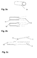
- the Figures 2a-2h show an embodiment of a method for producing a supply tube with such a tip.
- FIG. 1 schematically shows the distal end portion of a catheter system 1 of a self-expanding stent 3.
- the stent 3 is preferably made of nitinol and compressed in the delivery state shown in the figure housed in a distal end portion of a delivery tube 5, in which also - abutting proximal to the proximal end of the stent -
- a flexible push tube 7 is housed as a sliding element for releasing the stent.
- the delivery tube 5 is formed of an e-PTFE laminate, and in a distal end portion 5a, a temporarily adhered, compressed and curved, tapered tip portion is formed by impregnation with a stearic acid-based adhesive and thermocompression treatment in the manner described above.
- This lace area is relatively stiff when delivered. It is claimed during the advancement of the stent 3 by means of the push tube 7 through the stent to strain, and the adhesive matrix is broken and the material composite so far delaminated and reconfigured in a cylindrical to trumpet-shaped release state, which is mechanically much softer compared to the initial state.
- the high lubricity of the e-PTFE additionally facilitates the advancement of the stent, as well as, after its delivery, the withdrawal of the delivery tube from the corresponding vessel.
- FIG. 2a shows a cut piece 51 of an e-PTFE tube, which, as in FIG. 2b shown expanded with a suitable tool 10 (for example, a pair of pliers) on one side.
- the expanded e-PTFE tubing 52 is contacted by a suitable rod 11 with a cyanoacrylate adhesive and pushed onto the end of a delivery tube 5 ( Figures 2e, 2d) such that a delivery tubing tip preform as in FIG. 2f arises.
- This preform made of e-PTFE tube piece 52 and feed tube 5 is immersed in a vessel 12 with a solution 13 containing stearic acid ( Figure 2g ), so that the e-PTFE tube piece 52 is coated with this solution.
- the combination of coated e-PTFE tube piece 52 and feed tube 5 is pushed with a suitable punch 9 in a heatable mold 8 ( FIG. 2h ).
- the combination of e-PTFE tubing 52 and feed tube 5 is heated to above the melting temperature of the olefin matrix (above 76 ° C in this embodiment) and pressed together (compacted).
- such an inventive feeding tube 5 is formed with a distal end portion 5a which is formed as a tip in the context of the invention.
Landscapes
- Health & Medical Sciences (AREA)
- Life Sciences & Earth Sciences (AREA)
- Veterinary Medicine (AREA)
- Public Health (AREA)
- General Health & Medical Sciences (AREA)
- Animal Behavior & Ethology (AREA)
- Engineering & Computer Science (AREA)
- Biomedical Technology (AREA)
- Heart & Thoracic Surgery (AREA)
- Chemical & Material Sciences (AREA)
- Epidemiology (AREA)
- Child & Adolescent Psychology (AREA)
- Hematology (AREA)
- Chemical Kinetics & Catalysis (AREA)
- Anesthesiology (AREA)
- Pulmonology (AREA)
- Biophysics (AREA)
- Vascular Medicine (AREA)
- Transplantation (AREA)
- Cardiology (AREA)
- Oral & Maxillofacial Surgery (AREA)
- Molecular Biology (AREA)
- Medicinal Chemistry (AREA)
- Dispersion Chemistry (AREA)
- Materials For Medical Uses (AREA)
- Media Introduction/Drainage Providing Device (AREA)
Applications Claiming Priority (2)
| Application Number | Priority Date | Filing Date | Title |
|---|---|---|---|
| US201462050211P | 2014-09-15 | 2014-09-15 | |
| US201462050212P | 2014-09-15 | 2014-09-15 |
Publications (3)
| Publication Number | Publication Date |
|---|---|
| EP3000446A2 true EP3000446A2 (fr) | 2016-03-30 |
| EP3000446A3 EP3000446A3 (fr) | 2016-04-20 |
| EP3000446B1 EP3000446B1 (fr) | 2020-02-12 |
Family
ID=53488242
Family Applications (2)
| Application Number | Title | Priority Date | Filing Date |
|---|---|---|---|
| EP15173650.1A Active EP2995339B1 (fr) | 2014-09-15 | 2015-06-24 | Catheter a ballonnet |
| EP15173651.9A Active EP3000446B1 (fr) | 2014-09-15 | 2015-06-24 | Système de catheter et son procédé de fabrication |
Family Applications Before (1)
| Application Number | Title | Priority Date | Filing Date |
|---|---|---|---|
| EP15173650.1A Active EP2995339B1 (fr) | 2014-09-15 | 2015-06-24 | Catheter a ballonnet |
Country Status (2)
| Country | Link |
|---|---|
| US (2) | US20160074632A1 (fr) |
| EP (2) | EP2995339B1 (fr) |
Families Citing this family (1)
| Publication number | Priority date | Publication date | Assignee | Title |
|---|---|---|---|---|
| WO2018067875A1 (fr) * | 2016-10-05 | 2018-04-12 | Microvention, Inc. | Systèmes de cathéter à ballonnet |
Family Cites Families (21)
| Publication number | Priority date | Publication date | Assignee | Title |
|---|---|---|---|---|
| WO2003006096A1 (fr) * | 2001-07-09 | 2003-01-23 | Argmed Kommanditbolag | Catheter de controle de circuit d'ecoulement a structure dilatable en entonnoir a la partie proximale et a structure tubulaire a la partie distale et systeme de perfusion dote d'un tel catheter |
| JP4351832B2 (ja) * | 2002-08-05 | 2009-10-28 | テルモ株式会社 | バルーンカテーテル |
| US7468070B2 (en) * | 2004-01-23 | 2008-12-23 | Boston Scientific Scimed, Inc. | Stent delivery catheter |
| US8308789B2 (en) * | 2004-07-16 | 2012-11-13 | W. L. Gore & Associates, Inc. | Deployment system for intraluminal devices |
| US7892592B1 (en) * | 2004-11-30 | 2011-02-22 | Advanced Cardiovascular Systems, Inc. | Coating abluminal surfaces of stents and other implantable medical devices |
| US7632296B2 (en) * | 2005-03-03 | 2009-12-15 | Boston Scientific Scimed, Inc. | Rolling membrane with hydraulic recapture means for self expanding stent |
| US20080045896A1 (en) * | 2006-08-17 | 2008-02-21 | Abott Laboratories | Catheter having intermediate position markers |
| US8153181B2 (en) * | 2006-11-14 | 2012-04-10 | Boston Scientific Scimed, Inc. | Medical devices and related methods |
| US8690823B2 (en) * | 2007-07-13 | 2014-04-08 | Abbott Cardiovascular Systems Inc. | Drug coated balloon catheter |
| US20110137245A1 (en) * | 2007-09-12 | 2011-06-09 | Cook Medical Technologies Llc | Balloon catheter with embedded rod |
| EP2419167A1 (fr) * | 2009-04-13 | 2012-02-22 | Cook Medical Technologies LLC | Cathéter à ballonnet enduit |
| US9180274B2 (en) * | 2010-09-09 | 2015-11-10 | W. L. G ore & Associates, Inc | Indwelling luminal devices |
| US9327101B2 (en) * | 2010-09-17 | 2016-05-03 | Abbott Cardiovascular Systems Inc. | Length and diameter adjustable balloon catheter |
| EP2450010B1 (fr) * | 2010-11-09 | 2013-11-20 | Biotronik AG | Cathéter à ballonnet, notamment destiné à l'administration de médicaments ou de stents dans la zone d'une sténose |
| EP2709711B8 (fr) * | 2011-05-18 | 2017-03-22 | Vatrix Medical, Inc. | Ballonnets revêtus pour stabilisation des vaisseaux sanguins |
| EP2822635B8 (fr) * | 2012-03-09 | 2018-11-14 | Clearstream Technologies Limited | Ballonnet médical comprenant un identificateur radiopaque pour identifier avec précision la surface de travail |
| CN104968389B (zh) * | 2012-12-31 | 2018-11-06 | 明讯科技有限公司 | 辐射不可透过的球囊导管以及用于方便对齐的导丝 |
| EP2991718B1 (fr) * | 2013-05-03 | 2019-11-13 | C.R. Bard, Inc. | Gaine protectrice pouvant être pelée |
| WO2015059099A1 (fr) * | 2013-10-22 | 2015-04-30 | Tulip Endovascular Innovation Limited | Système et procédé d'administration d'un agent thérapeutique en direction des artères |
| US20150190618A1 (en) * | 2014-01-09 | 2015-07-09 | Medtronic Vascular, Inc. | Balloon Catheter With Elastomeric Sheath and Methods |
| US10569063B2 (en) * | 2014-10-03 | 2020-02-25 | W. L. Gore & Associates, Inc. | Removable covers for drug eluting medical devices |
-
2015
- 2015-06-24 EP EP15173650.1A patent/EP2995339B1/fr active Active
- 2015-06-24 EP EP15173651.9A patent/EP3000446B1/fr active Active
- 2015-08-12 US US14/824,257 patent/US20160074632A1/en not_active Abandoned
- 2015-08-17 US US14/827,871 patent/US20160074187A1/en not_active Abandoned
Non-Patent Citations (1)
| Title |
|---|
| None |
Also Published As
| Publication number | Publication date |
|---|---|
| EP2995339A3 (fr) | 2016-08-31 |
| US20160074632A1 (en) | 2016-03-17 |
| EP3000446B1 (fr) | 2020-02-12 |
| EP3000446A3 (fr) | 2016-04-20 |
| US20160074187A1 (en) | 2016-03-17 |
| EP2995339B1 (fr) | 2020-01-08 |
| EP2995339A2 (fr) | 2016-03-16 |
Similar Documents
| Publication | Publication Date | Title |
|---|---|---|
| EP1893272B1 (fr) | Auxiliaire d'introduction destiné à une trachéostomie percutanée | |
| EP0592726B1 (fr) | Cathéter avec un support vasculaire | |
| EP2496152B1 (fr) | Dispositif pour recanalisation d'un organe tubulaire, kit comprenant un tel dispositif et méthode pour sa fabrication | |
| EP1648313B1 (fr) | Dispositif de mise en place endoscopique de clips medicaux se refermant automatiquement | |
| EP1976466A1 (fr) | Systeme d'insertion de protheses intravasculaires a cinematique de traction-compression | |
| EP3041439B9 (fr) | Système d'insertion et de retrait d'implants | |
| DE202011107781U1 (de) | Prothesenanordnung zur Implantation in oder um ein Hohlorgan | |
| WO2013068127A1 (fr) | Dispositif pour implanter des éléments d'endoprothèse dans ou autour d'un organe creux | |
| EP2775968A1 (fr) | Dispositif pour implanter des éléments d'endoprothèse dans ou autour d'un organe creux | |
| DE102010038975A1 (de) | Zylinder für eine Penisprothese mit entfernbarem Führungsmittel | |
| EP3000446B1 (fr) | Système de catheter et son procédé de fabrication | |
| DE102006033399A1 (de) | Röntgenmarker zur präzisen Implantation von Stents | |
| DE102011054907B4 (de) | Transportdraht und Zufuhrsystem mit einem Transportdraht | |
| EP1529494B1 (fr) | Instrument pour le traitement de portions osseuses humaines ou animales | |
| DE102011121964B4 (de) | Katheter mit steuerbarer Katheterspitze | |
| DE102009060279B4 (de) | Vorrichtung zur Zufuhr eines medizinischen Implantats und Anordnung mit einer derartigen Vorrichtung | |
| DE102021113558B4 (de) | Vorrichtung zum Zuführen eines Implantats in ein Körperhohlgefäß und Anordnung mit einer solchen Vorrichtung | |
| EP1782745B1 (fr) | Marqueur de tissu comprenant un fil préformé fendu distalement | |
| DE102013104565B3 (de) | Pusher-Baugruppe für ein Einführsystem für ein selbstexpandierendes Gefäßimplantat sowie ein entsprechendes Einführsystem | |
| EP2149356A2 (fr) | Procédé et dispositif destinés au chargement d'un applicateur de stent | |
| EP1283025A1 (fr) | Dispositif à ballonets d'occlusion | |
| EP3225218A1 (fr) | Dispositif de catheter comprenant une capsule implantable reliee a la tige externe par des attaches | |
| WO2025194199A1 (fr) | Élément de pénétration | |
| EP2921143B1 (fr) | Instrument de tampon et système comprenant celui-ci destiné à traiter une structure osseuse ou de cartilage | |
| DE102015121545A1 (de) | Kathetersystem |
Legal Events
| Date | Code | Title | Description |
|---|---|---|---|
| PUAL | Search report despatched |
Free format text: ORIGINAL CODE: 0009013 |
|
| PUAI | Public reference made under article 153(3) epc to a published international application that has entered the european phase |
Free format text: ORIGINAL CODE: 0009012 |
|
| AK | Designated contracting states |
Kind code of ref document: A2 Designated state(s): AL AT BE BG CH CY CZ DE DK EE ES FI FR GB GR HR HU IE IS IT LI LT LU LV MC MK MT NL NO PL PT RO RS SE SI SK SM TR |
|
| AX | Request for extension of the european patent |
Extension state: BA ME |
|
| AK | Designated contracting states |
Kind code of ref document: A3 Designated state(s): AL AT BE BG CH CY CZ DE DK EE ES FI FR GB GR HR HU IE IS IT LI LT LU LV MC MK MT NL NO PL PT RO RS SE SI SK SM TR |
|
| AX | Request for extension of the european patent |
Extension state: BA ME |
|
| RIC1 | Information provided on ipc code assigned before grant |
Ipc: A61M 25/10 20060101ALI20160316BHEP Ipc: A61F 2/966 20130101AFI20160316BHEP Ipc: A61L 29/04 20060101ALI20160316BHEP Ipc: A61M 25/06 20060101ALN20160316BHEP |
|
| 17P | Request for examination filed |
Effective date: 20160919 |
|
| RBV | Designated contracting states (corrected) |
Designated state(s): AL AT BE BG CH CY CZ DE DK EE ES FI FR GB GR HR HU IE IS IT LI LT LU LV MC MK MT NL NO PL PT RO RS SE SI SK SM TR |
|
| STAA | Information on the status of an ep patent application or granted ep patent |
Free format text: STATUS: EXAMINATION IS IN PROGRESS |
|
| 17Q | First examination report despatched |
Effective date: 20170823 |
|
| GRAP | Despatch of communication of intention to grant a patent |
Free format text: ORIGINAL CODE: EPIDOSNIGR1 |
|
| STAA | Information on the status of an ep patent application or granted ep patent |
Free format text: STATUS: GRANT OF PATENT IS INTENDED |
|
| RIC1 | Information provided on ipc code assigned before grant |
Ipc: A61M 25/06 20060101ALN20190815BHEP Ipc: A61L 29/04 20060101ALI20190815BHEP Ipc: A61F 2/966 20130101AFI20190815BHEP Ipc: A61M 25/10 20130101ALI20190815BHEP |
|
| INTG | Intention to grant announced |
Effective date: 20190913 |
|
| GRAS | Grant fee paid |
Free format text: ORIGINAL CODE: EPIDOSNIGR3 |
|
| GRAA | (expected) grant |
Free format text: ORIGINAL CODE: 0009210 |
|
| STAA | Information on the status of an ep patent application or granted ep patent |
Free format text: STATUS: THE PATENT HAS BEEN GRANTED |
|
| AK | Designated contracting states |
Kind code of ref document: B1 Designated state(s): AL AT BE BG CH CY CZ DE DK EE ES FI FR GB GR HR HU IE IS IT LI LT LU LV MC MK MT NL NO PL PT RO RS SE SI SK SM TR |
|
| REG | Reference to a national code |
Ref country code: GB Ref legal event code: FG4D Free format text: NOT ENGLISH |
|
| REG | Reference to a national code |
Ref country code: CH Ref legal event code: EP |
|
| REG | Reference to a national code |
Ref country code: AT Ref legal event code: REF Ref document number: 1231128 Country of ref document: AT Kind code of ref document: T Effective date: 20200215 |
|
| REG | Reference to a national code |
Ref country code: IE Ref legal event code: FG4D Free format text: LANGUAGE OF EP DOCUMENT: GERMAN |
|
| REG | Reference to a national code |
Ref country code: DE Ref legal event code: R096 Ref document number: 502015011674 Country of ref document: DE |
|
| REG | Reference to a national code |
Ref country code: NL Ref legal event code: FP |
|
| PG25 | Lapsed in a contracting state [announced via postgrant information from national office to epo] |
Ref country code: FI Free format text: LAPSE BECAUSE OF FAILURE TO SUBMIT A TRANSLATION OF THE DESCRIPTION OR TO PAY THE FEE WITHIN THE PRESCRIBED TIME-LIMIT Effective date: 20200212 Ref country code: RS Free format text: LAPSE BECAUSE OF FAILURE TO SUBMIT A TRANSLATION OF THE DESCRIPTION OR TO PAY THE FEE WITHIN THE PRESCRIBED TIME-LIMIT Effective date: 20200212 Ref country code: NO Free format text: LAPSE BECAUSE OF FAILURE TO SUBMIT A TRANSLATION OF THE DESCRIPTION OR TO PAY THE FEE WITHIN THE PRESCRIBED TIME-LIMIT Effective date: 20200512 |
|
| REG | Reference to a national code |
Ref country code: LT Ref legal event code: MG4D |
|
| PG25 | Lapsed in a contracting state [announced via postgrant information from national office to epo] |
Ref country code: GR Free format text: LAPSE BECAUSE OF FAILURE TO SUBMIT A TRANSLATION OF THE DESCRIPTION OR TO PAY THE FEE WITHIN THE PRESCRIBED TIME-LIMIT Effective date: 20200513 Ref country code: BG Free format text: LAPSE BECAUSE OF FAILURE TO SUBMIT A TRANSLATION OF THE DESCRIPTION OR TO PAY THE FEE WITHIN THE PRESCRIBED TIME-LIMIT Effective date: 20200512 Ref country code: HR Free format text: LAPSE BECAUSE OF FAILURE TO SUBMIT A TRANSLATION OF THE DESCRIPTION OR TO PAY THE FEE WITHIN THE PRESCRIBED TIME-LIMIT Effective date: 20200212 Ref country code: SE Free format text: LAPSE BECAUSE OF FAILURE TO SUBMIT A TRANSLATION OF THE DESCRIPTION OR TO PAY THE FEE WITHIN THE PRESCRIBED TIME-LIMIT Effective date: 20200212 Ref country code: LV Free format text: LAPSE BECAUSE OF FAILURE TO SUBMIT A TRANSLATION OF THE DESCRIPTION OR TO PAY THE FEE WITHIN THE PRESCRIBED TIME-LIMIT Effective date: 20200212 Ref country code: IS Free format text: LAPSE BECAUSE OF FAILURE TO SUBMIT A TRANSLATION OF THE DESCRIPTION OR TO PAY THE FEE WITHIN THE PRESCRIBED TIME-LIMIT Effective date: 20200612 |
|
| PG25 | Lapsed in a contracting state [announced via postgrant information from national office to epo] |
Ref country code: ES Free format text: LAPSE BECAUSE OF FAILURE TO SUBMIT A TRANSLATION OF THE DESCRIPTION OR TO PAY THE FEE WITHIN THE PRESCRIBED TIME-LIMIT Effective date: 20200212 Ref country code: CZ Free format text: LAPSE BECAUSE OF FAILURE TO SUBMIT A TRANSLATION OF THE DESCRIPTION OR TO PAY THE FEE WITHIN THE PRESCRIBED TIME-LIMIT Effective date: 20200212 Ref country code: RO Free format text: LAPSE BECAUSE OF FAILURE TO SUBMIT A TRANSLATION OF THE DESCRIPTION OR TO PAY THE FEE WITHIN THE PRESCRIBED TIME-LIMIT Effective date: 20200212 Ref country code: DK Free format text: LAPSE BECAUSE OF FAILURE TO SUBMIT A TRANSLATION OF THE DESCRIPTION OR TO PAY THE FEE WITHIN THE PRESCRIBED TIME-LIMIT Effective date: 20200212 Ref country code: EE Free format text: LAPSE BECAUSE OF FAILURE TO SUBMIT A TRANSLATION OF THE DESCRIPTION OR TO PAY THE FEE WITHIN THE PRESCRIBED TIME-LIMIT Effective date: 20200212 Ref country code: SM Free format text: LAPSE BECAUSE OF FAILURE TO SUBMIT A TRANSLATION OF THE DESCRIPTION OR TO PAY THE FEE WITHIN THE PRESCRIBED TIME-LIMIT Effective date: 20200212 Ref country code: LT Free format text: LAPSE BECAUSE OF FAILURE TO SUBMIT A TRANSLATION OF THE DESCRIPTION OR TO PAY THE FEE WITHIN THE PRESCRIBED TIME-LIMIT Effective date: 20200212 Ref country code: SK Free format text: LAPSE BECAUSE OF FAILURE TO SUBMIT A TRANSLATION OF THE DESCRIPTION OR TO PAY THE FEE WITHIN THE PRESCRIBED TIME-LIMIT Effective date: 20200212 Ref country code: PT Free format text: LAPSE BECAUSE OF FAILURE TO SUBMIT A TRANSLATION OF THE DESCRIPTION OR TO PAY THE FEE WITHIN THE PRESCRIBED TIME-LIMIT Effective date: 20200705 |
|
| REG | Reference to a national code |
Ref country code: DE Ref legal event code: R097 Ref document number: 502015011674 Country of ref document: DE |
|
| PLBE | No opposition filed within time limit |
Free format text: ORIGINAL CODE: 0009261 |
|
| STAA | Information on the status of an ep patent application or granted ep patent |
Free format text: STATUS: NO OPPOSITION FILED WITHIN TIME LIMIT |
|
| 26N | No opposition filed |
Effective date: 20201113 |
|
| PG25 | Lapsed in a contracting state [announced via postgrant information from national office to epo] |
Ref country code: IT Free format text: LAPSE BECAUSE OF FAILURE TO SUBMIT A TRANSLATION OF THE DESCRIPTION OR TO PAY THE FEE WITHIN THE PRESCRIBED TIME-LIMIT Effective date: 20200212 Ref country code: MC Free format text: LAPSE BECAUSE OF FAILURE TO SUBMIT A TRANSLATION OF THE DESCRIPTION OR TO PAY THE FEE WITHIN THE PRESCRIBED TIME-LIMIT Effective date: 20200212 |
|
| PG25 | Lapsed in a contracting state [announced via postgrant information from national office to epo] |
Ref country code: PL Free format text: LAPSE BECAUSE OF FAILURE TO SUBMIT A TRANSLATION OF THE DESCRIPTION OR TO PAY THE FEE WITHIN THE PRESCRIBED TIME-LIMIT Effective date: 20200212 Ref country code: SI Free format text: LAPSE BECAUSE OF FAILURE TO SUBMIT A TRANSLATION OF THE DESCRIPTION OR TO PAY THE FEE WITHIN THE PRESCRIBED TIME-LIMIT Effective date: 20200212 |
|
| GBPC | Gb: european patent ceased through non-payment of renewal fee |
Effective date: 20200624 |
|
| PG25 | Lapsed in a contracting state [announced via postgrant information from national office to epo] |
Ref country code: LU Free format text: LAPSE BECAUSE OF NON-PAYMENT OF DUE FEES Effective date: 20200624 |
|
| REG | Reference to a national code |
Ref country code: BE Ref legal event code: MM Effective date: 20200630 |
|
| PG25 | Lapsed in a contracting state [announced via postgrant information from national office to epo] |
Ref country code: GB Free format text: LAPSE BECAUSE OF NON-PAYMENT OF DUE FEES Effective date: 20200624 |
|
| PG25 | Lapsed in a contracting state [announced via postgrant information from national office to epo] |
Ref country code: BE Free format text: LAPSE BECAUSE OF NON-PAYMENT OF DUE FEES Effective date: 20200630 |
|
| PGFP | Annual fee paid to national office [announced via postgrant information from national office to epo] |
Ref country code: DE Payment date: 20210625 Year of fee payment: 7 Ref country code: FR Payment date: 20210622 Year of fee payment: 7 Ref country code: NL Payment date: 20210621 Year of fee payment: 7 |
|
| REG | Reference to a national code |
Ref country code: AT Ref legal event code: MM01 Ref document number: 1231128 Country of ref document: AT Kind code of ref document: T Effective date: 20200624 |
|
| PGFP | Annual fee paid to national office [announced via postgrant information from national office to epo] |
Ref country code: CH Payment date: 20210623 Year of fee payment: 7 Ref country code: IE Payment date: 20210622 Year of fee payment: 7 |
|
| PG25 | Lapsed in a contracting state [announced via postgrant information from national office to epo] |
Ref country code: AT Free format text: LAPSE BECAUSE OF NON-PAYMENT OF DUE FEES Effective date: 20200624 |
|
| PG25 | Lapsed in a contracting state [announced via postgrant information from national office to epo] |
Ref country code: TR Free format text: LAPSE BECAUSE OF FAILURE TO SUBMIT A TRANSLATION OF THE DESCRIPTION OR TO PAY THE FEE WITHIN THE PRESCRIBED TIME-LIMIT Effective date: 20200212 Ref country code: MT Free format text: LAPSE BECAUSE OF FAILURE TO SUBMIT A TRANSLATION OF THE DESCRIPTION OR TO PAY THE FEE WITHIN THE PRESCRIBED TIME-LIMIT Effective date: 20200212 Ref country code: CY Free format text: LAPSE BECAUSE OF FAILURE TO SUBMIT A TRANSLATION OF THE DESCRIPTION OR TO PAY THE FEE WITHIN THE PRESCRIBED TIME-LIMIT Effective date: 20200212 |
|
| PG25 | Lapsed in a contracting state [announced via postgrant information from national office to epo] |
Ref country code: MK Free format text: LAPSE BECAUSE OF FAILURE TO SUBMIT A TRANSLATION OF THE DESCRIPTION OR TO PAY THE FEE WITHIN THE PRESCRIBED TIME-LIMIT Effective date: 20200212 Ref country code: AL Free format text: LAPSE BECAUSE OF FAILURE TO SUBMIT A TRANSLATION OF THE DESCRIPTION OR TO PAY THE FEE WITHIN THE PRESCRIBED TIME-LIMIT Effective date: 20200212 |
|
| REG | Reference to a national code |
Ref country code: DE Ref legal event code: R119 Ref document number: 502015011674 Country of ref document: DE |
|
| REG | Reference to a national code |
Ref country code: CH Ref legal event code: PL |
|
| REG | Reference to a national code |
Ref country code: NL Ref legal event code: MM Effective date: 20220701 |
|
| PG25 | Lapsed in a contracting state [announced via postgrant information from national office to epo] |
Ref country code: NL Free format text: LAPSE BECAUSE OF NON-PAYMENT OF DUE FEES Effective date: 20220701 |
|
| PG25 | Lapsed in a contracting state [announced via postgrant information from national office to epo] |
Ref country code: LI Free format text: LAPSE BECAUSE OF NON-PAYMENT OF DUE FEES Effective date: 20220630 Ref country code: IE Free format text: LAPSE BECAUSE OF NON-PAYMENT OF DUE FEES Effective date: 20220624 Ref country code: FR Free format text: LAPSE BECAUSE OF NON-PAYMENT OF DUE FEES Effective date: 20220630 Ref country code: CH Free format text: LAPSE BECAUSE OF NON-PAYMENT OF DUE FEES Effective date: 20220630 |
|
| PG25 | Lapsed in a contracting state [announced via postgrant information from national office to epo] |
Ref country code: DE Free format text: LAPSE BECAUSE OF NON-PAYMENT OF DUE FEES Effective date: 20230103 |