EP3000594A1 - Nanopartikel zur verbesserung der dimensionsstabilität von harzen - Google Patents
Nanopartikel zur verbesserung der dimensionsstabilität von harzen Download PDFInfo
- Publication number
- EP3000594A1 EP3000594A1 EP15186477.4A EP15186477A EP3000594A1 EP 3000594 A1 EP3000594 A1 EP 3000594A1 EP 15186477 A EP15186477 A EP 15186477A EP 3000594 A1 EP3000594 A1 EP 3000594A1
- Authority
- EP
- European Patent Office
- Prior art keywords
- resin
- polymer nanoparticles
- cte
- heat
- resin mixture
- Prior art date
- Legal status (The legal status is an assumption and is not a legal conclusion. Google has not performed a legal analysis and makes no representation as to the accuracy of the status listed.)
- Granted
Links
Images






Classifications
-
- B—PERFORMING OPERATIONS; TRANSPORTING
- B32—LAYERED PRODUCTS
- B32B—LAYERED PRODUCTS, i.e. PRODUCTS BUILT-UP OF STRATA OF FLAT OR NON-FLAT, e.g. CELLULAR OR HONEYCOMB, FORM
- B32B7/00—Layered products characterised by the relation between layers; Layered products characterised by the relative orientation of features between layers, or by the relative values of a measurable parameter between layers, i.e. products comprising layers having different physical, chemical or physicochemical properties; Layered products characterised by the interconnection of layers
- B32B7/03—Layered products characterised by the relation between layers; Layered products characterised by the relative orientation of features between layers, or by the relative values of a measurable parameter between layers, i.e. products comprising layers having different physical, chemical or physicochemical properties; Layered products characterised by the interconnection of layers with respect to the orientation of features
-
- C—CHEMISTRY; METALLURGY
- C08—ORGANIC MACROMOLECULAR COMPOUNDS; THEIR PREPARATION OR CHEMICAL WORKING-UP; COMPOSITIONS BASED THEREON
- C08L—COMPOSITIONS OF MACROMOLECULAR COMPOUNDS
- C08L83/00—Compositions of macromolecular compounds obtained by reactions forming in the main chain of the macromolecule a linkage containing silicon with or without sulfur, nitrogen, oxygen or carbon only; Compositions of derivatives of such polymers
- C08L83/04—Polysiloxanes
-
- B—PERFORMING OPERATIONS; TRANSPORTING
- B32—LAYERED PRODUCTS
- B32B—LAYERED PRODUCTS, i.e. PRODUCTS BUILT-UP OF STRATA OF FLAT OR NON-FLAT, e.g. CELLULAR OR HONEYCOMB, FORM
- B32B27/00—Layered products comprising a layer of synthetic resin
- B32B27/12—Layered products comprising a layer of synthetic resin next to a fibrous or filamentary layer
-
- B—PERFORMING OPERATIONS; TRANSPORTING
- B32—LAYERED PRODUCTS
- B32B—LAYERED PRODUCTS, i.e. PRODUCTS BUILT-UP OF STRATA OF FLAT OR NON-FLAT, e.g. CELLULAR OR HONEYCOMB, FORM
- B32B27/00—Layered products comprising a layer of synthetic resin
- B32B27/28—Layered products comprising a layer of synthetic resin comprising synthetic resins not wholly covered by any one of the sub-groups B32B27/30 - B32B27/42
- B32B27/281—Layered products comprising a layer of synthetic resin comprising synthetic resins not wholly covered by any one of the sub-groups B32B27/30 - B32B27/42 comprising polyimides
-
- B—PERFORMING OPERATIONS; TRANSPORTING
- B32—LAYERED PRODUCTS
- B32B—LAYERED PRODUCTS, i.e. PRODUCTS BUILT-UP OF STRATA OF FLAT OR NON-FLAT, e.g. CELLULAR OR HONEYCOMB, FORM
- B32B27/00—Layered products comprising a layer of synthetic resin
- B32B27/28—Layered products comprising a layer of synthetic resin comprising synthetic resins not wholly covered by any one of the sub-groups B32B27/30 - B32B27/42
- B32B27/285—Layered products comprising a layer of synthetic resin comprising synthetic resins not wholly covered by any one of the sub-groups B32B27/30 - B32B27/42 comprising polyethers
-
- B—PERFORMING OPERATIONS; TRANSPORTING
- B32—LAYERED PRODUCTS
- B32B—LAYERED PRODUCTS, i.e. PRODUCTS BUILT-UP OF STRATA OF FLAT OR NON-FLAT, e.g. CELLULAR OR HONEYCOMB, FORM
- B32B27/00—Layered products comprising a layer of synthetic resin
- B32B27/30—Layered products comprising a layer of synthetic resin comprising vinyl (co)polymers; comprising acrylic (co)polymers
- B32B27/308—Layered products comprising a layer of synthetic resin comprising vinyl (co)polymers; comprising acrylic (co)polymers comprising acrylic (co)polymers
-
- B—PERFORMING OPERATIONS; TRANSPORTING
- B32—LAYERED PRODUCTS
- B32B—LAYERED PRODUCTS, i.e. PRODUCTS BUILT-UP OF STRATA OF FLAT OR NON-FLAT, e.g. CELLULAR OR HONEYCOMB, FORM
- B32B27/00—Layered products comprising a layer of synthetic resin
- B32B27/32—Layered products comprising a layer of synthetic resin comprising polyolefins
-
- B—PERFORMING OPERATIONS; TRANSPORTING
- B32—LAYERED PRODUCTS
- B32B—LAYERED PRODUCTS, i.e. PRODUCTS BUILT-UP OF STRATA OF FLAT OR NON-FLAT, e.g. CELLULAR OR HONEYCOMB, FORM
- B32B27/00—Layered products comprising a layer of synthetic resin
- B32B27/34—Layered products comprising a layer of synthetic resin comprising polyamides
-
- B—PERFORMING OPERATIONS; TRANSPORTING
- B32—LAYERED PRODUCTS
- B32B—LAYERED PRODUCTS, i.e. PRODUCTS BUILT-UP OF STRATA OF FLAT OR NON-FLAT, e.g. CELLULAR OR HONEYCOMB, FORM
- B32B27/00—Layered products comprising a layer of synthetic resin
- B32B27/36—Layered products comprising a layer of synthetic resin comprising polyesters
-
- B—PERFORMING OPERATIONS; TRANSPORTING
- B32—LAYERED PRODUCTS
- B32B—LAYERED PRODUCTS, i.e. PRODUCTS BUILT-UP OF STRATA OF FLAT OR NON-FLAT, e.g. CELLULAR OR HONEYCOMB, FORM
- B32B27/00—Layered products comprising a layer of synthetic resin
- B32B27/40—Layered products comprising a layer of synthetic resin comprising polyurethanes
-
- B—PERFORMING OPERATIONS; TRANSPORTING
- B32—LAYERED PRODUCTS
- B32B—LAYERED PRODUCTS, i.e. PRODUCTS BUILT-UP OF STRATA OF FLAT OR NON-FLAT, e.g. CELLULAR OR HONEYCOMB, FORM
- B32B5/00—Layered products characterised by the non- homogeneity or physical structure, i.e. comprising a fibrous, filamentary, particulate or foam layer; Layered products characterised by having a layer differing constitutionally or physically in different parts
- B32B5/02—Layered products characterised by the non- homogeneity or physical structure, i.e. comprising a fibrous, filamentary, particulate or foam layer; Layered products characterised by having a layer differing constitutionally or physically in different parts characterised by structural features of a fibrous or filamentary layer
- B32B5/024—Woven fabric
-
- B—PERFORMING OPERATIONS; TRANSPORTING
- B32—LAYERED PRODUCTS
- B32B—LAYERED PRODUCTS, i.e. PRODUCTS BUILT-UP OF STRATA OF FLAT OR NON-FLAT, e.g. CELLULAR OR HONEYCOMB, FORM
- B32B5/00—Layered products characterised by the non- homogeneity or physical structure, i.e. comprising a fibrous, filamentary, particulate or foam layer; Layered products characterised by having a layer differing constitutionally or physically in different parts
- B32B5/22—Layered products characterised by the non- homogeneity or physical structure, i.e. comprising a fibrous, filamentary, particulate or foam layer; Layered products characterised by having a layer differing constitutionally or physically in different parts characterised by the presence of two or more layers which are next to each other and are fibrous, filamentary, formed of particles or foamed
- B32B5/24—Layered products characterised by the non- homogeneity or physical structure, i.e. comprising a fibrous, filamentary, particulate or foam layer; Layered products characterised by having a layer differing constitutionally or physically in different parts characterised by the presence of two or more layers which are next to each other and are fibrous, filamentary, formed of particles or foamed one layer being a fibrous or filamentary layer
- B32B5/26—Layered products characterised by the non- homogeneity or physical structure, i.e. comprising a fibrous, filamentary, particulate or foam layer; Layered products characterised by having a layer differing constitutionally or physically in different parts characterised by the presence of two or more layers which are next to each other and are fibrous, filamentary, formed of particles or foamed one layer being a fibrous or filamentary layer another layer next to it also being fibrous or filamentary
-
- C—CHEMISTRY; METALLURGY
- C08—ORGANIC MACROMOLECULAR COMPOUNDS; THEIR PREPARATION OR CHEMICAL WORKING-UP; COMPOSITIONS BASED THEREON
- C08J—WORKING-UP; GENERAL PROCESSES OF COMPOUNDING; AFTER-TREATMENT NOT COVERED BY SUBCLASSES C08B, C08C, C08F, C08G or C08H
- C08J5/00—Manufacture of articles or shaped materials containing macromolecular substances
- C08J5/005—Reinforced macromolecular compounds with nanosized materials, e.g. nanoparticles, nanofibres, nanotubes, nanowires, nanorods or nanolayered materials
-
- C—CHEMISTRY; METALLURGY
- C08—ORGANIC MACROMOLECULAR COMPOUNDS; THEIR PREPARATION OR CHEMICAL WORKING-UP; COMPOSITIONS BASED THEREON
- C08L—COMPOSITIONS OF MACROMOLECULAR COMPOUNDS
- C08L23/00—Compositions of homopolymers or copolymers of unsaturated aliphatic hydrocarbons having only one carbon-to-carbon double bond; Compositions of derivatives of such polymers
- C08L23/02—Compositions of homopolymers or copolymers of unsaturated aliphatic hydrocarbons having only one carbon-to-carbon double bond; Compositions of derivatives of such polymers not modified by chemical after-treatment
- C08L23/04—Homopolymers or copolymers of ethene
- C08L23/06—Polyethylene
-
- C—CHEMISTRY; METALLURGY
- C08—ORGANIC MACROMOLECULAR COMPOUNDS; THEIR PREPARATION OR CHEMICAL WORKING-UP; COMPOSITIONS BASED THEREON
- C08L—COMPOSITIONS OF MACROMOLECULAR COMPOUNDS
- C08L23/00—Compositions of homopolymers or copolymers of unsaturated aliphatic hydrocarbons having only one carbon-to-carbon double bond; Compositions of derivatives of such polymers
- C08L23/02—Compositions of homopolymers or copolymers of unsaturated aliphatic hydrocarbons having only one carbon-to-carbon double bond; Compositions of derivatives of such polymers not modified by chemical after-treatment
- C08L23/10—Homopolymers or copolymers of propene
- C08L23/12—Polypropene
-
- C—CHEMISTRY; METALLURGY
- C08—ORGANIC MACROMOLECULAR COMPOUNDS; THEIR PREPARATION OR CHEMICAL WORKING-UP; COMPOSITIONS BASED THEREON
- C08L—COMPOSITIONS OF MACROMOLECULAR COMPOUNDS
- C08L33/00—Compositions of homopolymers or copolymers of compounds having one or more unsaturated aliphatic radicals, each having only one carbon-to-carbon double bond, and only one being terminated by only one carboxyl radical, or of salts, anhydrides, esters, amides, imides or nitriles thereof; Compositions of derivatives of such polymers
-
- C—CHEMISTRY; METALLURGY
- C08—ORGANIC MACROMOLECULAR COMPOUNDS; THEIR PREPARATION OR CHEMICAL WORKING-UP; COMPOSITIONS BASED THEREON
- C08L—COMPOSITIONS OF MACROMOLECULAR COMPOUNDS
- C08L61/00—Compositions of condensation polymers of aldehydes or ketones; Compositions of derivatives of such polymers
- C08L61/04—Condensation polymers of aldehydes or ketones with phenols only
- C08L61/16—Condensation polymers of aldehydes or ketones with phenols only of ketones with phenols
-
- C—CHEMISTRY; METALLURGY
- C08—ORGANIC MACROMOLECULAR COMPOUNDS; THEIR PREPARATION OR CHEMICAL WORKING-UP; COMPOSITIONS BASED THEREON
- C08L—COMPOSITIONS OF MACROMOLECULAR COMPOUNDS
- C08L63/00—Compositions of epoxy resins; Compositions of derivatives of epoxy resins
-
- C—CHEMISTRY; METALLURGY
- C08—ORGANIC MACROMOLECULAR COMPOUNDS; THEIR PREPARATION OR CHEMICAL WORKING-UP; COMPOSITIONS BASED THEREON
- C08L—COMPOSITIONS OF MACROMOLECULAR COMPOUNDS
- C08L67/00—Compositions of polyesters obtained by reactions forming a carboxylic ester link in the main chain; Compositions of derivatives of such polymers
-
- C—CHEMISTRY; METALLURGY
- C08—ORGANIC MACROMOLECULAR COMPOUNDS; THEIR PREPARATION OR CHEMICAL WORKING-UP; COMPOSITIONS BASED THEREON
- C08L—COMPOSITIONS OF MACROMOLECULAR COMPOUNDS
- C08L69/00—Compositions of polycarbonates; Compositions of derivatives of polycarbonates
-
- C—CHEMISTRY; METALLURGY
- C08—ORGANIC MACROMOLECULAR COMPOUNDS; THEIR PREPARATION OR CHEMICAL WORKING-UP; COMPOSITIONS BASED THEREON
- C08L—COMPOSITIONS OF MACROMOLECULAR COMPOUNDS
- C08L71/00—Compositions of polyethers obtained by reactions forming an ether link in the main chain; Compositions of derivatives of such polymers
-
- C—CHEMISTRY; METALLURGY
- C08—ORGANIC MACROMOLECULAR COMPOUNDS; THEIR PREPARATION OR CHEMICAL WORKING-UP; COMPOSITIONS BASED THEREON
- C08L—COMPOSITIONS OF MACROMOLECULAR COMPOUNDS
- C08L75/00—Compositions of polyureas or polyurethanes; Compositions of derivatives of such polymers
- C08L75/04—Polyurethanes
-
- C—CHEMISTRY; METALLURGY
- C08—ORGANIC MACROMOLECULAR COMPOUNDS; THEIR PREPARATION OR CHEMICAL WORKING-UP; COMPOSITIONS BASED THEREON
- C08L—COMPOSITIONS OF MACROMOLECULAR COMPOUNDS
- C08L77/00—Compositions of polyamides obtained by reactions forming a carboxylic amide link in the main chain; Compositions of derivatives of such polymers
-
- C—CHEMISTRY; METALLURGY
- C08—ORGANIC MACROMOLECULAR COMPOUNDS; THEIR PREPARATION OR CHEMICAL WORKING-UP; COMPOSITIONS BASED THEREON
- C08L—COMPOSITIONS OF MACROMOLECULAR COMPOUNDS
- C08L81/00—Compositions of macromolecular compounds obtained by reactions forming in the main chain of the macromolecule a linkage containing sulfur with or without nitrogen, oxygen or carbon only; Compositions of polysulfones; Compositions of derivatives of such polymers
- C08L81/04—Polysulfides
-
- C—CHEMISTRY; METALLURGY
- C08—ORGANIC MACROMOLECULAR COMPOUNDS; THEIR PREPARATION OR CHEMICAL WORKING-UP; COMPOSITIONS BASED THEREON
- C08L—COMPOSITIONS OF MACROMOLECULAR COMPOUNDS
- C08L81/00—Compositions of macromolecular compounds obtained by reactions forming in the main chain of the macromolecule a linkage containing sulfur with or without nitrogen, oxygen or carbon only; Compositions of polysulfones; Compositions of derivatives of such polymers
- C08L81/06—Polysulfones; Polyethersulfones
-
- H—ELECTRICITY
- H01—ELECTRIC ELEMENTS
- H01B—CABLES; CONDUCTORS; INSULATORS; SELECTION OF MATERIALS FOR THEIR CONDUCTIVE, INSULATING OR DIELECTRIC PROPERTIES
- H01B1/00—Conductors or conductive bodies characterised by the conductive materials; Selection of materials as conductors
- H01B1/06—Conductors or conductive bodies characterised by the conductive materials; Selection of materials as conductors mainly consisting of other non-metallic substances
- H01B1/12—Conductors or conductive bodies characterised by the conductive materials; Selection of materials as conductors mainly consisting of other non-metallic substances organic substances
- H01B1/124—Intrinsically conductive polymers
- H01B1/128—Intrinsically conductive polymers comprising six-membered aromatic rings in the main chain, e.g. polyanilines, polyphenylenes
-
- B—PERFORMING OPERATIONS; TRANSPORTING
- B32—LAYERED PRODUCTS
- B32B—LAYERED PRODUCTS, i.e. PRODUCTS BUILT-UP OF STRATA OF FLAT OR NON-FLAT, e.g. CELLULAR OR HONEYCOMB, FORM
- B32B2255/00—Coating on the layer surface
- B32B2255/26—Polymeric coating
-
- B—PERFORMING OPERATIONS; TRANSPORTING
- B32—LAYERED PRODUCTS
- B32B—LAYERED PRODUCTS, i.e. PRODUCTS BUILT-UP OF STRATA OF FLAT OR NON-FLAT, e.g. CELLULAR OR HONEYCOMB, FORM
- B32B2260/00—Layered product comprising an impregnated, embedded, or bonded layer wherein the layer comprises an impregnation, embedding, or binder material
- B32B2260/02—Composition of the impregnated, bonded or embedded layer
- B32B2260/021—Fibrous or filamentary layer
-
- B—PERFORMING OPERATIONS; TRANSPORTING
- B32—LAYERED PRODUCTS
- B32B—LAYERED PRODUCTS, i.e. PRODUCTS BUILT-UP OF STRATA OF FLAT OR NON-FLAT, e.g. CELLULAR OR HONEYCOMB, FORM
- B32B2260/00—Layered product comprising an impregnated, embedded, or bonded layer wherein the layer comprises an impregnation, embedding, or binder material
- B32B2260/04—Impregnation, embedding, or binder material
- B32B2260/046—Synthetic resin
-
- B—PERFORMING OPERATIONS; TRANSPORTING
- B32—LAYERED PRODUCTS
- B32B—LAYERED PRODUCTS, i.e. PRODUCTS BUILT-UP OF STRATA OF FLAT OR NON-FLAT, e.g. CELLULAR OR HONEYCOMB, FORM
- B32B2262/00—Composition or structural features of fibres which form a fibrous or filamentary layer or are present as additives
- B32B2262/10—Inorganic fibres
- B32B2262/101—Glass fibres
-
- B—PERFORMING OPERATIONS; TRANSPORTING
- B32—LAYERED PRODUCTS
- B32B—LAYERED PRODUCTS, i.e. PRODUCTS BUILT-UP OF STRATA OF FLAT OR NON-FLAT, e.g. CELLULAR OR HONEYCOMB, FORM
- B32B2262/00—Composition or structural features of fibres which form a fibrous or filamentary layer or are present as additives
- B32B2262/10—Inorganic fibres
- B32B2262/103—Metal fibres
-
- B—PERFORMING OPERATIONS; TRANSPORTING
- B32—LAYERED PRODUCTS
- B32B—LAYERED PRODUCTS, i.e. PRODUCTS BUILT-UP OF STRATA OF FLAT OR NON-FLAT, e.g. CELLULAR OR HONEYCOMB, FORM
- B32B2262/00—Composition or structural features of fibres which form a fibrous or filamentary layer or are present as additives
- B32B2262/10—Inorganic fibres
- B32B2262/105—Ceramic fibres
-
- B—PERFORMING OPERATIONS; TRANSPORTING
- B32—LAYERED PRODUCTS
- B32B—LAYERED PRODUCTS, i.e. PRODUCTS BUILT-UP OF STRATA OF FLAT OR NON-FLAT, e.g. CELLULAR OR HONEYCOMB, FORM
- B32B2264/00—Composition or properties of particles which form a particulate layer or are present as additives
- B32B2264/02—Synthetic macromolecular particles
-
- C—CHEMISTRY; METALLURGY
- C08—ORGANIC MACROMOLECULAR COMPOUNDS; THEIR PREPARATION OR CHEMICAL WORKING-UP; COMPOSITIONS BASED THEREON
- C08J—WORKING-UP; GENERAL PROCESSES OF COMPOUNDING; AFTER-TREATMENT NOT COVERED BY SUBCLASSES C08B, C08C, C08F, C08G or C08H
- C08J2300/00—Characterised by the use of unspecified polymers
- C08J2300/24—Thermosetting resins
Definitions
- tougheners often increase the viscosity of the resin which may impair manufacturability and thus effectively limit the amount of toughener that can be added to the resin.
- Advanced thermoset resins typically require relatively high cure temperatures (e.g., 350-600°F) to fully cure the thermoset resin/composite. Such high cure temperatures may result in increased thermally-induced stresses and strains due to the differential CTE between the fibers and resin.
- the above-noted needs associated with resins are specifically addressed by the present disclosure which provides a composition that may include a plurality of polymer nanoparticles in a resin to form a resin mixture.
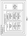
- the resin may have a resin coefficient of thermal expansion (CTE), a resin cure shrinkage, and/or a resin heat of reaction.
- the polymer nanoparticles may have a nanoparticle cure shrinkage that may be less than the resin cure shrinkage, a nanoparticle CTE that is different than the resin CTE, and/or a nanoparticle heat of reaction that is less than the resin heat of reaction.
- an increase in temperature of the resin 116 may result in an increase in the volume of the resin 116.
- a decrease in the temperature of the resin 116 may result in a decrease in the volume of the resin 116.
- the resin cure shrinkage 120 may be described as the shrinking of the resin volume during the cross-linking reaction or polymerization of the resin 116 as the resin 116 cures and changes from a liquid to a solid. Cure shrinkage of the resin 116 may be a linear function of the degree of cure.
- the resin heat of reaction 126 may be described as the energy or heat that is released from the resin 116 during the cross-linking or polymerization of the resin 116 during the curing process.
- resin cure shrinkage 120 and/or resin-fiber CTE mismatch may result in internal stresses in the resin 116 ( Figure 1 ) of a cured composite structure 100.
- Such internal stresses may result in undesirable effects including, but not limited to, microcracking in the resin 116, shape distortion 102 ( Figure 6A ) or warpage of the cured composite structure 100, a reduction in the mechanical properties of the composite structure 100, and other effects.
- internal stress in the resin 116 may compromise the integrity of the composite structure 100 during mechanical loading and/or thermal cycling of the composite structure 100.
- Excessive resin heat of reaction 126 during curing of the resin 116 may increase the temperature the resin 116 beyond predetermined resin temperature limits.
- excessive heat release by the resin 116 ( Figure 1 ) during curing may result in thicker sections of a composite layup 106 getting hotter than thinner section due to the increased volume of resin 116 in the thicker sections.
- Differential heating of the composite layup 106 ( Figure 2 ) may result in distortion or warpage of the composite structure 100 during cool down from an elevated curing temperature.
- excessive resin heat of reaction 126 ( Figure 1 ) may result in changes in the extent of resin cure following the curing cycle.
- excessive resin heat of reaction 126 may cause overheating of the resin 116 which may result in a reduction in the mechanical strength and performance of the composite structure 100.
- excessive heat of reaction during resin cure may result in the resin 116 exceeding its combustion temperature which may result in the combustion (e.g., fire) of the resin 116 or composite layup 106 and surrounding equipment, and which may be accompanied by the release of undesirable organics.
- the present disclosure may advantageously include the addition of a plurality of polymer nanoparticles 200 to the resin 116 to form a resin mixture 128.
- the polymer nanoparticles 200 may be selected to alter the resin properties and avoid one or more undesirable effects associated with unmodified resin.
- unmodified resin may be described as resin not containing polymer nanoparticles 200.
- the polymer nanoparticles 200 may be a least partially solidified and/or pre-cured prior to curing the resin 116 which may ensure the stability of the polymer nanoparticles 200 in the resin 116.
- the polymer nanoparticles 200 may be completely or substantially solidified and/or substantially cured prior to curing the resin 116.
- Polymer nanoparticles 200 that are partially pre-cured prior to mixing with the resin 116 may be post-cured during the resin curing or solidification cycle.
- Polymer nanoparticles 200 may be added to thermosetting resins and to thermoplastic resins to tailor the properties of the resins.
- the polymer nanoparticles 200 may be provided in a broad spectrum of materials which may facilitate the ability to tailor a wide range or resin properties over a wide range of property values.
- a resin mixture 128 may include polymer nanoparticles 200 that have a nanoparticle cure shrinkage 204 (e.g., during the resin cure cycle) that is less than the resin cure shrinkage 120 ( Figure 1 ). As described in greater detail below, by adding polymer nanoparticles 200 that have a lower cure shrinkage 204 than the resin cure shrinkage 120, the cure shrinkage 132 ( Figure 7A ) of the resin mixture 128 may be reduced relative to the cure shrinkage of resin not containing polymer nanoparticles 200 (e.g., unmodified resin).
- a resin mixture 128 may include polymer nanoparticles 200 that have a nanoparticle CTE 206 ( Figure 1 ) that may be different than the resin CTE 122.
- polymer nanoparticles 200 may be added to resin 116 wherein the polymer nanoparticles 200 have a nanoparticle CTE 206 that is lower than the resin CTE 122.
- the lower nanoparticle CTE 206 may effectively reduce the resin mixture CTE 134 ( Figure 1 ), and may thereby reduce the CTE mismatch between the resin mixture 128 and the reinforcing fibers 150 ( Figure 1 ) of a composite layup 106.
- a resin mixture 128 may include polymer nanoparticles 200 that have a nanoparticle heat of reaction 210 that may be less than the resin heat of reaction 126.
- a low nanoparticle heat of reaction 210 ( Figure 14A ) may result in an effective reduction in the heat of reaction 138 ( Figure 14A ) of a resin mixture 128 containing the polymer nanoparticles 200.
- the reduced heat of reaction 210 of the polymer nanoparticles 200 ( Figure 1 ) may be exhibited during the resin cure cycle and, in particular, during the peak reaction time of the resin 116 ( Figure 1 ) during the cure cycle.
- a resin mixture 128 of polymer nanoparticles 200 and resin 116 may be implemented in other applications including, but not limited to, adhesives, coatings, injection moldable plastics, and any one of a variety of other applications.
- the polymer nanoparticles 200 may be added to thermosetting resins 116 ( Figure 1 ) and to thermoplastic resins 116 for both prepreg systems and resin infusion systems.
- the polymer nanoparticles 200 may be added to tailor the properties of the resin 116 and improve the processing, manufacturability, and performance of a composite structure.
- a composite structure 100 may be formed of composite plies 108 that may be pre-impregnated with resin 116 (e.g., prepreg composite plies 108) containing polymer nanoparticles 200 ( Figure 1 ).
- resin 116 e.g., prepreg composite plies 108
- one or more composite plies 108 of a composite structure 100 may be formed of prepreg fiber tows 150 ( Figure 2 ), prepreg unidirectional tape 154 ( Figure 2 ), prepreg woven fabric, braided prepregs (not shown), and other forms of prepreg.
- the composite structure 100 may be laid up with composite plies 108 that may be pre-impregnated with unmodified resin 116, after which polymer nanoparticles 200 may be applied to one or more locations of the composite layup 106.
- a composite structure 100 may be formed as one or more dry fiber preforms 156 which may be infused with resin 116.
- a composite structure 100 may be formed by laying up dry fiber tows 150, dry unidirectional tape 154 ( Figure 2 ), dry fiber sheets (not shown), dry woven fabric (not shown), and/or other forms of dry fiber.
- the dry fiber preforms 156 may be arranged in a stack of composite plies 108 into which resin 116 may be infused in a wet layup process.
- unmodified resin 116 may be infused into a dry fiber preform 156 ( Figure 2 ), after which polymer nanoparticles 200 may be applied to one or more locations of the composite layup 106 ( Figure 2 ).
- polymer nanoparticles 200 may be applied to resin-rich pockets (not shown) of a composite layup 106.
- a resin mixture 128 containing polymer nanoparticles 200 may be infused into a dry fiber preform 156 resulting in the polymer nanoparticles 200 distributed in bulk throughout the composite layup 106.
- the resin 116 may be formed from thermoplastic material or thermosetting material.
- Thermoplastic material may include at least one of the following: acrylics, fluorocarbons, polyamides, polyethylenes, polyesters, polypropylenes, polycarbonates, polyurethanes, polyaryletherketones, and polyetherimides.
- Thermosetting material may include at least one of the following: polyurethanes, phenolics, polyimides, bismaleimides, polyesters, benzoxazines, condensation polymers, cyanate esters, siloxanes, epoxies, thiols, and phenolics.
- the reinforcing filaments 152 or fibers 150 may be formed from materials such as carbons, silicon carbide, boron, ceramic, and metallic material.
- the reinforcing filaments 152 or fibers 150 may also be formed from glass such as E-glass (alumino-borosilicate glass), S-glass (alumino silicate glass), pure silica, borosilicate glass, optical glass, and other glass compositions.
- the polymer nanoparticles 200 may be formed of any one of the above-described thermosetting materials or thermoplastic materials.
- the polymer nanoparticles 200 may be formed of bismaleimides, polyesters, polyurethanes, polyimides, benzoxazines, condensation polymers, cyanate esters, siloxanes, epoxies, thiols, and phenolics.
- the polymer nanoparticles 200 may also be formed of polyaryletherketones including, but not limited to, polyetheretherketone (PEEK), polyetherketoneketone (PEKK), and polyetherketoneetherketone (PEKEK).
- the polymer nanoparticles 200 may be provided in a cross-sectional width 202 ( Figure 7 ) or particle diameter of 10-200 nanometers. In some examples, the polymer nanoparticles 200 may have a cross-sectional width 202 of between 10-100 nanometers. However, in other examples, the polymer nanoparticles 200 ( Figure 3 ) may have a cross-sectional width 202 of up to 2 microns. Providing the polymer nanoparticles 200 in a relatively small cross-sectional width 202 may prevent or reduce filtering out of overly-large nanoparticles during prepregging operations or during resin infusion. In this regard, an overly-large nanoparticle may prevent passage of the nanoparticle between adjacent reinforcing fibers 150 ( Figure 2 ) or tows.
- the polymer nanoparticles 200 may also be provided in one or more geometric shapes.
- the polymer nanoparticles 200 may have a generally spherical or rounded outer shape to avoid increasing the resin 116 ( Figure 1 ) viscosity.
- the polymer nanoparticles 200 may be provided as a solid sphere, a hollow sphere, and/or as a core-sheath nanoparticle (not shown).
- Core-sheath nanoparticles may include a spherical sheath encapsulating a core which may be formed of a different material than the sheath.
- the sheath may be formed of thermoplastic material and the core may be formed of silica or the core may be a carbon nanotube having an anisotropic CTE or a directional CTE that may be oriented in a specific direction similar to that which is shown in Figures 9-11 and described below.
- Polymer nanoparticles 200 may optionally be provided in non-spherical shapes that may be shaped to minimize the effect on of the resin 116.
- the polymer nanoparticles 200 may be provided in generally rounded shapes such as oblong or elliptical shapes, or as a three-dimensional faceted shapes including, but not limited to, cubes, rectangles, pyramids, and other shapes.
- the relatively small cross-sectional width 202 ( Figure 7 ) and/or the generally rounded shape (e.g., spherical) of the polymer nanoparticles 200 may allow for a relatively high concentration of polymer nanoparticles 200 within the resin 116 ( Figure 1 ) with a relatively small increase in resin viscosity.
- the polymer nanoparticles 200 may constitute up to 75 percent by volume of a resin mixture 128 containing resin 116 and polymer nanoparticles 200.
- the polymer nanoparticles 200 may constitute a minimum of 10 percent by volume of a resin mixture 128 as the low end of a range of volumetric percentage of polymer nanoparticles 200.
- polymer nanoparticles 200 it may be desirable to provide the polymer nanoparticles 200 at a maximum of 65 percent by volume of a resin mixture 128 as a high end of a range of percentage by volume of polymer nanoparticles 200.
- the polymer nanoparticles 200 may constitute no more than 50 percent by volume as the high end of the range.
- polymer nanoparticles 200 may be provided in any combination of the above-mentioned low end and high end of the range of volumetric percentage of polymer nanoparticles 200 of a resin mixture 128.
- Figure 3 shows a cross-section of a portion of the composite structure 100 of Figure 2 and illustrating the reinforcing filaments 152 that make up the unidirectional composite plies 108.
- one or more of the composite plies 108 may be formed of unidirectional tape 154.
- the fibers 150 in one of the composite plies 108 may be oriented non-parallel to the fibers 150 in other composite plies 108.
- any one or more of the composite plies 108 may have a fiber orientation that is parallel to the fibers 150 in an adjacent composite ply 108.
- the reinforcing filaments 152 in the uppermost and lowermost composite plies 108 are oriented along a direction perpendicular to the plane of the paper.
- a resin mixture 128 ( Figure 2 ) containing polymer nanoparticles 200 may be used to pre-impregnate any one of a variety of different fiber forms including, but not limited to, fiber tows, unidirectional tape, unidirectional sheet, woven fabric, braided fibers, and any one of a variety of other crimp and non-crimp fiber forms.
- the viscosity of the resin 116 in the prepreg plies may be reduced by applying heat to the resin 116 and/or the composite layup 106 and which may allow the polymer-nanoparticle-entrained resin 116 in the composite plies 108 to flow and intermingle.
- the polymer nanoparticles 200 may become uniformly distributed throughout the composite layup 106, after which heat and/or pressure may be applied to consolidate and/or cure the composite layup 106 to form the final composite structure 100.
- a composite layup 106 may be fabricated using dry fiber preforms such as dry unidirectional tape, dry unidirectional sheet, dry woven fabric, dry braided fibers, etc.
- a liquid resin mixture 128 ( Figure 2 ) containing polymer nanoparticles 200 may be infused into a composite layup 106 after which heat and/or pressure may be applied to consolidate and/or cure the composite layup 106.
- a composite layup 106 may be formed of composite plies 108 ( Figure 4 ) that may be pre-impregnated with unmodified resin 116.
- polymer nanoparticles 200 may be selectively applied to target locations in the composite layup 106 such as by applying and/or spraying a solution containing polymer nanoparticles 200 into resin-rich pockets (not shown) of the composite layup 106.
- a resin-rich pocket may be described as a high-resin-content location in the composite layup 106 or composite structure 100, or a location that has a large volume of resin 116 relative to the volume of fibers 150 ( Figure 3 ) at the specific location.
- Placement of polymer nanoparticles 200 at one or more locations of a composite layup 106 may be performed manually and/or by using a robotic device (not shown).
- Polymer nanoparticles 200 may be applied onto reinforcing filaments 152 and/or to fiber tows 150 during manufacturing of the reinforcing filaments 152 and/or to fiber tows 150, and which may later be formed into unidirectional tape, unidirectional sheet, woven fabric, and other crimp and non-crimp fiber forms.
- Polymer nanoparticles 200 may also be applied to a fiber form (e.g., unidirectional tape, woven fabric, braided fibers, etc.) during prepregging operations.
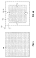
- Figure 5 is a schematic illustration of a conventional uncured unmodified resin 116 with no nanoparticles in the unmodified resin 116.
- Figure 5A is a schematic illustration of the conventional cured unmodified resin 116 of Figure 5 and showing the resin net shrinkage 118 that may occur during and/or as a result of the curing of the unmodified resin 116.
- the resin net shrinkage 118 may be the result of the resin cure shrinkage 120 of the resin 116, and/or the result of resin contraction 124 of the resin 116.
- Cure shrinkage may be described as the chemical shrinkage of a resin during the cross-linking or polymerization of the resin as the resin changes from a liquid to a solid.
- Contraction may be described as the shrinkage of a resin during cool down of the now-hardened or solidified composite structure 100 after curing.
- Figure 6 is a schematic illustration of a conventional uncured composite layup 106 made from unidirectional plies 112 ( Figure 4 ) and including unmodified resin 116. Reinforcing fibers 150 may be embedded within the unmodified resin 116.
- the composite structure 100 has a curved shape and includes changes in the direction of the reinforcing fibers 150.
- the reinforcing fibers 150 may be made of carbon and the unmodified resin 116 may be an epoxy resin.
- phantom lines in Figure 6 representing a geometric tolerance boundary 104 of the composite structure 100.
- the tolerance boundary 104 may represent an outer limit of the geometry or shape of the final, cured composite structure 100 as may be required such that the final composite structure 100 may fit with mating components.
- the curvature of the composite structure 100 and the associated directional changes of the reinforcing fibers 150, coupled with any changes in the fiber volume fraction that may exist along the length of the composite structure 100 may result in an inhomogeneous dimensional change in the composite structure 100 during resin cure and cool down.
- the high level of cure shrinkage and/or contraction of the epoxy resin 116 may result in significant distortion 102 of the overall shape of the cured composite structure 100 which may exceed the geometric tolerance boundary 104.
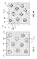
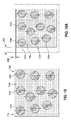
- Figure 7 is a schematic illustration of an uncured thermoset resin mixture 128 containing a plurality of polymer nanoparticles 200 formed of a different material than the resin 116.
- the polymer nanoparticles 200 may have lower cure shrinkage 204 than the resin cure shrinkage 120.
- the polymer nanoparticles 200 may also have a lower CTE 206 than the resin CTE 122 ( Figure 1 ).
- the polymer nanoparticles 200 may be pre-cured or pre-solidified prior to the curing of the resin 116.
- Figure 7A is a schematic illustration of the cured resin mixture 128 of Figure 7 and showing a reduction in the net shrinkage 130 of the resin mixture 128 relative to the net shrinkage 118 of the unmodified resin 116 as shown in Figure 5 .
- the reduction in the net shrinkage 130 of the resin mixture 128 in Figure 7A may be the result of the lower cure shrinkage 204 and/or lower contraction 208 of the polymer nanoparticles 200.
- the reduction in the net shrinkage 130 of the resin mixture 128 may be reduced as a result of a reduction in the total volume of resin 116 due to the polymer nanoparticles 200 occupying a portion of the resin 116.
- Figure 8 is a schematic illustration of an uncured composite layup 106 made from unidirectional plies 112 similar to the composite layup 106 ( Figure 4 ) shown in Figure 6 , with the exception that the composite layup 106 of Figure 8 may include a resin mixture 128 containing polymer nanoparticles 200.
- the polymer nanoparticles 200 may be formed of a material that is not made from the same constituents as the resin 116.
- the polymer nanoparticles 200 may be pre-cured and/or pre-solidified and may thereby avoid nanoparticle cure shrinkage 204 ( Figure 7A ) during the curing of the resin 116.
- Figure 8A is a schematic illustration of the cured composite structure 100 of Figure 8 showing a reduction in the shape distortion 102 ( Figure 6A ) of the overall shape of the composite structure 100 relative to the distortion of the composite structure 100 shown in Figure 6A .
- the reduction in shape distortion 102 in Figure 8A may be the result of the nanoparticle cure shrinkage 204 being lower than the resin cure shrinkage 120, and/or the result of the nanoparticle contraction 208 ( Figure 7A ) being lower than the resin contraction 124 due to the nanoparticle CTE 206 being lower than the resin CTE 122.
- the addition of the polymer nanoparticles 200 provides a means to control the resin mixture CTE 134 such that a composite structure 100 may be manufactured with a final shape that is within the geometric tolerance boundary 104 ( Figure 6A ).
- Figure 9 is a schematic illustration of an uncured resin mixture 128 containing a plurality of directional-CTE polymer nanoparticles 214. At least some of the directional-CTE polymer nanoparticles 214 in the resin mixture 128 may have having a CTE along at least one axis that is different than the CTE along another axis of the polymer nanoparticle 214. For example, the directional-CTE polymer nanoparticles 214 may have an axis along which the CTE is lower (e.g., the axis of lower CTE 216) than the CTE of the polymer nanoparticle 200 along another axis (e.g., the axis of higher CTE 218).
- a directional-CTE polymer nanoparticle 214 may have an axis of lower CTE 216, an axis of higher CTE 218 oriented orthogonal to the axis of lower CTE 216, and an axis of medium CTE (not shown) oriented orthogonal to the axis of lower CTE 216 and the axis of higher CTE 218.
- Figure 9A is a schematic illustration of a non-limiting example of a device for orienting the CTE axes of directional-CTE polymer nanoparticles 214.
- the example includes a spaced pair of elements 220 such as bars or plates across which a potential difference or charge may be applied to generate an electric and/or magnetic field.
- the directional-CTE polymer nanoparticles 214 may be configured such that diametrically opposite sides of each nanoparticle are oppositely charged along a selected CTE axis.
- Electric or magnetic field lines 222 may be generated by applying a potential difference across the spaced pair of elements 220, and causing the CTE axes of the polymer nanoparticles 214 to align with the magnetic field lines 222.
- the nanoparticles may be configured such that the axes of lower CTE 216 are aligned with the electric and/or magnetic field lines 222.
- Figure 10 is a schematic illustration of an uncured resin mixture 128 directional-CTE polymer nanoparticles 214 wherein the axes of lower CTE 216 are aligned with one another. Each one of the directional-CTE polymer nanoparticles 214 may also include an axis of higher CTE 218 which may be oriented orthogonally to the axes of lower CTE 214.
- Figure 10A is a schematic illustration of the resin mixture 128 of Figure 10 following curing of the resin mixture 128.
- the directional-CTE polymer nanoparticles 214 may result in lower contraction 224 of the resin mixture 128 along a direction parallel to the axes of lower CTE, and higher contraction 226 of the resin mixture 128 along a direction parallel to the axes of higher CTE.
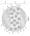
- Figure 11 is a schematic illustration of a portion of the composite layup 106 of Figure 4 showing directional-CTE polymer nanoparticles 214 contained in the resin mixture 128.
- the directional-CTE polymer nanoparticles 214 may be oriented to align the axes of lower CTE 214 along a common direction.
- an electric or magnetic field may be applied to an uncured resin mixture 128 ( Figure 10 ) such that that the axes of lower CTE 216 are oriented transverse to a lengthwise direction of the reinforcing filaments 152 or fibers 150.
- a transverse orientation of the axes of lower CTE 214 may reduce contraction of the resin mixture 128 relative to contraction of unmodified resin.
- the reduced contraction along a direction transverse to the reinforcing fibers 150 may reduce thermally-induced stresses in the resin 116 which may prevent or reduce crack initiation or crack growth in the resin 116 during cool down of the resin 116 from curing and/or during thermal cycling of the composite structure 100 during service.
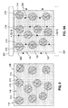
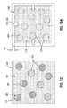
- Figure 12 is a schematic illustration of an uncured resin mixture 128 including a thermoset resin 116 containing a plurality of cured polymer nanoparticles 200 formed of the same material as the thermoset resin 116. Due to the pre-curing of the polymer nanoparticles 200, the polymer nanoparticles 200 may have no cure shrinkage during curing of the resin 116.
- Figure 12A is a schematic illustration of the cured resin mixture 128 of Figure 14 showing a reduction in the net shrinkage 132 relative to the net shrinkage 118 of unmodified resin 116 as shown in Figure 5A .
- the reduction in the net shrinkage 132 of the resin mixture 128 may be due to the absence of cure shrinkage of the cured polymer nanoparticles 200.
- the reduction in net shrinkage of the resin mixture 128 may also be due to the polymer nanoparticles 200 physically constraining the resin cure shrinkage 120 and/or the resin contraction 124.
- Figure 13 is a schematic illustration of a conventional uncured unmodified thermoset resin 116 with no nanoparticles in the unmodified resin 116.
- Figure 13A is a schematic illustration of the cured unmodified thermoset resin 116 of Figure 13 and showing significant heat of reaction 126 generated by the unmodified thermoset resin 116 during cure.
- a large amount of heat release 126 during curing of a resin 116 may undesirably increase the temperature of a composite layup 106 during curing.
- the large heat release 126 may result in distortion or warpage of the final shape of the composite structure 100 ( Figure 11 ), particularly in thick sections of the composite layup 106.
- the large heat release 126 during curing of a resin 116 may result in a reduction in the mechanical properties of the resin 116 due to overheating, and may additionally result in hazardous combustion of the resin 116, and/or changes in the extent of cure the resin 116 during the curing cycle.
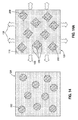
- Figure 14 is a schematic illustration of an uncured thermoset resin mixture 128 advantageously containing a plurality of polymer nanoparticles 200 formed of a different material than the resin 116.
- the polymer nanoparticles 200 may have a nanoparticle heat of reaction 210 ( Figure 14A ) that may be lower than the resin heat of reaction 126 ( Figure 13A ) during resin cure.
- Figure 14A is a schematic illustration of the cured thermoset resin mixture 128 of Figure 14 and showing a reduced heat of reaction 138 of the resin mixture 128 relative to the heat of reaction 126 of the unmodified resin 116 shown in Figure 13A .
- the reduction in the heat of reaction 138 of the resin mixture 128 in Figure 14A may result in a net reduction in part temperature which may advantageously reduce the amount of part distortion otherwise caused by non-uniform part temperatures in a composite layup during resin cure, and/or may avoid exceeding the resin degradation temperature during resin cure. Additionally, the use of nanoparticles 200 with a lower nanoparticle CTE 206 may further reduce internal stresses caused by resin-fiber CTE mismatch.
- Figure 15 is a schematic illustration of an uncured thermoset resin mixture 128 containing a plurality of cured polymer nanoparticles 200 formed of the same material as the resin 116.
- the cured polymer nanoparticles 200 may exhibit no (e.g., zero) nanoparticle heat of reaction 210 during resin cure.
- polymer nanoparticles 200 formed of the same or different material than the resin may have a nanoparticle heat capacity (Cp) that may be selected to reduce a maximum temperature of the resin 116.
- Figure 15A is a schematic illustration of the cured thermoset resin mixture 128 of Figure 15 .
- the cured polymer nanoparticles 200 may function as a non-reactive heat sink and may absorb a portion of the resin heat of reaction 126 ( Figure 13A ) during resin cure, and which may result in a reduction in the part temperature due to the lower amount of heat generated by the curing resin 116.
- a reduction in the heat of reaction 138 may reduce the part temperature during resin cure which may advantageously reduce the amount of part distortion otherwise caused by non-uniform part temperatures in the composite layup.
- a reduction in the temperature of the composite structure 100 may avoid exceeding the degradation or combustion temperature of the resin 116.
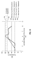
- Figure 16 is a plot of a slow cure cycle and a fast cure cycle of a conventional composite layup 106 which may be formed of reinforcing fibers 150 embedded in unmodified resin 116 ( Figure 8A ).
- the reinforcing fibers 150 may be carbon fibers embedded in epoxy resin.
- the plot of Figure 16 plots resin cure time 250 along the horizontal axis, and cure temperature 252 along the vertical axis.
- the plot includes a dashed horizontal line representing the combustion temperature limit 254 of the resin 116, and a dotted horizontal line representing the degradation temperature limit 256 of the resin 116.
- the plot illustrates a fast cure part temperature 258 and a fast cure oven temperature 260 as may be used in a fast cure cycle of the composite layup 106 ( Figure 13A ).
- the plot also illustrates a slow cure part temperature 262 and a slow cure oven temperature 264 as may be used in a slow cure cycle of the composite layup 106.
- the resin heat of reaction 126 increases the temperature of the composite layup 106 to above the cure temperature as set by an oven or autoclave.
- the temperature of the composite layup 106 may exceed the combustion temperature limit 254 ( Figure 16 ) of the resin 116 which may result in damage to the composite layup 106 ( Figure 13A ) due to overheating.
- exceeding the degradation temperature limit 256 may also result in a reduction in the mechanical strength and performance of the resin 116 ( Figure 15A ) which may compromise the integrity of the composite structure 100.
- exceeding the combustion temperature limit 254 may potentially result in combustion or fire with the potential for damaging the surrounding composite structure 100 and equipment.
- the slow cure cycle may mitigate damage to the composite layup 106 ( Figure 13A ) to avoid overheating.
- the slow cure cycle may provide additional time for the resin heat of reaction 126 ( Figure 13A ) to dissipate from the composite layup 106 during cure and which may reduce the temperature overshoot such that the maximum temperature of the composite layup 106 remains below the degradation temperature limit 256 of the resin 116 ( Figure 15A ).
- the slow cure cycle increases the overall processing time for manufacturing a composite structure 100.
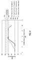
- Figure 17 is a plot of the slow cure cycle and the fast cure cycle of a composite layup 106 including a resin mixture 128 containing polymer nanoparticles 200.
- the polymer nanoparticles 200 may have a nanoparticle cure shrinkage 204 ( Figure 7A ) that is less than the resin cure shrinkage 120 ( Figure 5A ), a nanoparticle CTE 206 that is lower or different than the resin CTE 122, and/or a nanoparticle heat of reaction 210 that is less than the resin heat of reaction 126.
- the polymer nanoparticles 200 result in a net reduction in the heat of reaction 138 of the resin mixture 128 ( Figure 15A ) during curing as compared to the heat of reaction 126 of an unmodified resin 116 as shown in Figure 16 .
- the reduction in the heat of reaction 138 of the resin mixture 128 results in a reduction in the temperature of the composite layup 106 which may thereby avoid damage due to overheating.
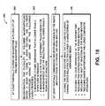
- Figure 18 is a flowchart illustrating one or more operations that may be included in a method 300 of manufacturing a composite structure 100.
- Step 302 of the method 300 may include providing a plurality of polymer nanoparticles 200, and at least partially curing or solidifying the polymer nanoparticles 200 prior to curing the resin 116.
- the polymer nanoparticles 200 ( Figure 4 ) may be formed of any one of a variety of different thermosetting materials or thermoplastic materials.
- the method may include fabricating the polymer nanoparticles 200 externally prior to mixing with the resin 116 ( Figure 5 ).
- the polymer nanoparticles 200 may be formed in a relatively small size and may have a generally rounded or spherical shape to avoid increasing the resin viscosity.
- the relatively small size of the polymer nanoparticles 200 may reduce or minimize the effect of the polymer nanoparticles 200 on the ability of the resin 116 to flow and/or infuse into the fibers 150 of a composite layup 106.
- the polymer nanoparticles 200 may have a particle cross-sectional width 202 ( Figure 7 ) of from 10-200 nanometers.
- the resin mixture 128 ( Figure 3 ) may include polymer nanoparticles 200 that have a particle cross-sectional width 202 that is different than the particle cross-sectional width 202 of other polymer nanoparticles 200 in the resin mixture 128.
- the polymer nanoparticles 200 may be formed of the same material as the resin 116 and may be partially or fully cured or solidified prior to curing the resin 116. In other examples, the polymer nanoparticles 200 may be formed of a different material than the resin 116 ( Figure 7 ), and may be partially or fully cured or solidified prior to curing the resin 116. In still further examples, a resin mixture 128 ( Figure 7 ) may contain some polymer nanoparticles 200 formed of one material, and other polymer nanoparticles 200 in the resin mixture 128 may be formed of a different material.
- providing polymer nanoparticles 200 ( Figure 7 ) formed of different materials and the same resin mixture 128 may provide a means for altering different properties of the resin 116.
- some of the polymer nanoparticles 200 in a resin mixture 128 may be formed of a material that has a nanoparticle cure shrinkage 204 ( Figure 7A ) that is less (e.g., during the resin 116 cure cycle) than the resin cure shrinkage 120 as a means to reduce the cumulative volumetric shrinkage 130 of the resin mixture 128.
- the same resin mixture 128 may also include polymer nanoparticles 200 which may be formed of another material which may have a lower nanoparticle heat of reaction 210 than the resin heat of reaction 126 as a means to reduce the total amount of heat generated during resin cure and thereby maintain the temperature of the resin 116 and composite layup 106 below predetermined limits such as below the degradation temperature 256 or below the combustion temperature 254 ( Figure 16 ).
- Step 304 of the method 300 may include incorporating or mixing the plurality of polymer nanoparticles 200 within resin 116 ( Figure 8A ) to form a resin mixture 128.
- the relatively small size and the rounded or spherical shape of the polymer nanoparticles 200 enables high load levels of polymer nanoparticles 200 in the resin mixture 128 ( Figure 8A ) with minimal effect on resin viscosity.
- the polymer nanoparticles 200 may constitute up to 75 percent by volume of the resin mixture 128.
- the polymer nanoparticles 200 may constitute a minimum of 10 percent by volume of a resin mixture 128 as the low end of a range of volumetric percentage of polymer nanoparticles 200.
- polymer nanoparticles 200 may be provided in any combination of the above-mentioned low end and high end of the range of volumetric percentage of polymer nanoparticles 200 of a resin mixture 128. As was also indicated above, some of the polymer nanoparticles 200 ( Figure 8 ) in a resin mixture 128 may have a different particle cross-sectional width 202 than other polymer nanoparticles 200 in the resin mixture 128.
- a resin mixture 128 may include high-heat-capacity polymer nanoparticles 200 of a relatively large diameter for the purpose of increasing the heat absorption 212 ( Figure 15A ) capability of the polymer nanoparticles 200.
- the same resin mixture 128 may also include polymer nanoparticles 200 of a smaller diameter which may be added for the purpose of reducing resin cure shrinkage 120 or reducing the resin heat of reaction 126 ( Figure 13A ).
- the method may include laying up composite plies 108 that may be pre-impregnated with unmodified resin 116, after which polymer nanoparticles 200 ( Figure 12 ) may be applied to one or more locations of the composite layup 106.
- the method may include laying up dry fiber preforms which may be infused with resin 116 which may contain polymer nanoparticles 200, or laying up dry fiber preforms followed by infusing with unmodified resin 116 and then applying polymer nanoparticles 200 to one or more locations of the composite layup 106.
- Step 308 of the method 300 may include curing or solidifying the resin mixture 128 which may include applying heat and/or pressure to the composite layup 106.
- the incorporation of polymer nanoparticles 200 in the resin 116 may improve the curing properties of the resin 116 and improve the mechanical performance of the composite structure.
- polymer nanoparticles 200 ( Figure 14A ) having relatively low nanoparticle cure shrinkage 204 may reduce dimensional or volumetric shrinkage relative to the volumetric shrinkage exhibit by unmodified resin 116.
- Polymer nanoparticles 200 with a low CTE may provide a means to control the CTE of the resin mixture 128 ( Figure 14A ) to reduce internal stress in the composite structure 100 during the cure cycle and reduce shape distortion 102 ( Figure 6A ) of the cured composite structure 100.
- the method may further include providing in the resin 116 at least some polymer nanoparticles 200 that have a predetermined nanoparticle heat capacity (C p ) selected to reduce a maximum temperature of the resin 116 ( Figure 15A ).
- the method may additionally include absorbing a portion of the resin heat of reaction 126 ( Figure 13A ) into the polymer nanoparticles 200 during curing of the resin mixture 128.
- the method may include reducing a maximum temperature of the resin mixture 128 ( Figure 15A ) in response to absorbing the resin heat of reaction 126 into the polymer nanoparticles 200.
- polymer nanoparticles 200 ( Figure 15A ) with a low heat of reaction may reduce shape distortion 102 of the cured composite structure 100 by reducing the total amount of heat generated during curing and thereby reducing the temperature of the composite layup 106 ( Figure 13A ) during curing which may reduce changes in the part shape due to thicker sections of the composite layup 106 curing earlier and hotter than thinner sections.
- the method may include coupling a plurality of polymer nanoparticles 200 to one or more reinforcing filaments 152 to act as spacers to prevent the reinforcing filaments 152 from touching one another and to control the permeability of the filaments 152.
- the polymer nanoparticles 200 may be applied to reinforcing filaments 152 as the reinforcing filaments 152 are drawn from a fiber forming apparatus (not shown).
- polymer nanoparticles 200 may be applied to reinforcing filaments 152 as the fiber tows 150 are formed into unidirectional tape, unidirectional sheet, woven fabric, braided fibers, and other fiber forms.
- polymer nanoparticles 200 may be melt-fused to the reinforcing filaments 152.
- the polymer nanoparticles 200 may be formed of thermoplastic material or the polymer nanoparticles 200 may be configured as core-sheath nanoparticles (not shown) each having a thermoplastic sheath surrounding a core.
- the reinforcing filaments 152 and/or the sheaths of the polymer nanoparticles may be heated to a temperature causing the outer portion of the core-sheath nanoparticles to bond or melt-fuse to the reinforcing filaments 152 when the core-sheath nanoparticles come into contact with the reinforcing filaments 152.
- Illustrative embodiments of the disclosure may be described in the context of a method (not shown) of manufacturing and/or servicing an aircraft, spacecraft, satellite, or other aerospace component.
- Pre-production, component manufacturing, and/or servicing may include specification and design of aerospace components and material procurement.
- During production, component and subassembly manufacturing, and system integration of aerospace components takes place. Thereafter, the aircraft, spacecraft, satellite, or other aerospace component may go through certification and delivery in order to be placed in service.
- aerospace components produced by the manufacturing and servicing method may include an airframe with a plurality of systems and an interior.
- the plurality of systems may include one or more of a propulsion system, an electrical system, a hydraulic system, and an environmental system. Any number of other systems may be included.
- an aerospace example is shown, different illustrative embodiments may be applied to other industries, such as the automotive industry.
- Apparatuses and methods embodied herein may be employed during at least one of the stages of an aerospace component manufacturing and/or servicing method.
- a composite structure 100 e.g., Figure 1
- a coating e.g., an injection-molded plastic, and/or an adhesive
- a composite structure may be manufactured during any one of the stages of the aerospace component manufacturing and servicing method.
- a composite structure may be manufactured during at least one of component and subassembly manufacturing, system integration, routine maintenance and service, or some other stage of aircraft manufacturing and servicing.
- a composite structure may be used in one or more structures of aerospace components.
- a composite structure may be included in a structure of an airframe, an interior, or some other part of an aircraft, spacecraft, satellite, or other aerospace component.
- a composition comprising a resin having at least one of a resin coefficient of thermal expansion (CTE), a resin cure shrinkage, and a resin heat of reaction, a plurality of polymer nanoparticles having at least one of the following properties: a nanoparticle cure shrinkage less than the resin cure shrinkage; a nanoparticle CTE different than the resin CTE; and a nanoparticle heat of reaction less than the resin heat of reaction and a resin mixture (128) which includes the addition of the plurality of polymer nanparticles to the resin.
- the composition is one wherein the polymer nanoparticles are at least partially cured prior to the curing of the resin.
- the composition is one wherein the resin and/or the polymer nanoparticles are comprised of at least one of the following: thermoplastic material, acrylics, fluorocarbons, polyamides, polyolefins, polyethylenes, polyesters, polycarbonates, polypropylenes, polyurethanes, polyaryletherketones, polyetherimides, polyethersulfone, polysulfone, and polyphenylsulfone; thermosetting material, polyurethanes, phenolics, polyimides, sulphonated polymer (polyphenylene sulphide), a conductive polymer (e.g., polyaniline), benzoxazines, bismaleimides, cyanate esthers, polyesters, epoxies, thiols, and silsesquioxanes.
- thermoplastic material acrylics, fluorocarbons, polyamides, polyolefins, polyethylenes, polyesters, polycarbonates, polypropylenes, polyure
- the composition is one wherein: the polymer nanoparticles have at least one of the following configurations: a solid homogenous sphere, a hollow homogenous sphere.
- the composition is one wherein: the polymer nanoparticles constitute no less than 10 percent by volume of a resin mixture and the polymer nanoparticles constitute up to 75 percent by volume of a resin mixture.
- a resin mixture of resin and polymer nanoparticles is included in at least one of the following: a coating, an adhesive, an injection moldable plastic, a resin matrix of a composite structure.
- a composite structure comprising: a resin having at least one of a resin coefficient of thermal expansion (CTE), a resin cure shrinkage, and a resin heat of reaction; a plurality of polymer nanoparticles having at least one of the following properties: a nanoparticle cure shrinkage less than the resin cure shrinkage; a nanoparticle CTE different than the resin CTE; a nanoparticle heat of reaction less than the resin heat of reaction; and a plurality of reinforcing fibers embedded within a resin mixture.
- the composite structure is one wherein: the reinforcing fibers include fiber tows, unidirectional tape, woven fabric, and/or braided fiber.
- a method of forming a composition comprising: incorporating a plurality of polymer nanoparticles within a resin to form a resin mixture; the polymer nanoparticles having at least one of the following properties: a nanoparticle cure shrinkage less than a resin cure shrinkage; a nanoparticle CTE different than a resin CTE; and a nanoparticle heat of reaction less than a resin heat of reaction.
- the method further includes at least partially curing the polymer nanoparticles prior to mixing with the resin.
- the method is one wherein the polymer nanoparticles constitute no less than 20 percent by volume of the resin mixture and the polymer nanoparticles constitute up to 75 percent by volume of the resin mixture.
Landscapes
- Chemical & Material Sciences (AREA)
- Health & Medical Sciences (AREA)
- Chemical Kinetics & Catalysis (AREA)
- Medicinal Chemistry (AREA)
- Polymers & Plastics (AREA)
- Organic Chemistry (AREA)
- Engineering & Computer Science (AREA)
- Materials Engineering (AREA)
- Physics & Mathematics (AREA)
- Spectroscopy & Molecular Physics (AREA)
- Textile Engineering (AREA)
- Nanotechnology (AREA)
- Manufacturing & Machinery (AREA)
- Reinforced Plastic Materials (AREA)
- Compositions Of Macromolecular Compounds (AREA)
Applications Claiming Priority (1)
| Application Number | Priority Date | Filing Date | Title |
|---|---|---|---|
| US14/493,371 US10808123B2 (en) | 2014-09-23 | 2014-09-23 | Nanoparticles for improving the dimensional stability of resins |
Publications (2)
| Publication Number | Publication Date |
|---|---|
| EP3000594A1 true EP3000594A1 (de) | 2016-03-30 |
| EP3000594B1 EP3000594B1 (de) | 2019-07-24 |
Family
ID=54325303
Family Applications (1)
| Application Number | Title | Priority Date | Filing Date |
|---|---|---|---|
| EP15186477.4A Active EP3000594B1 (de) | 2014-09-23 | 2015-09-23 | Nanopartikel zur verbesserung der dimensionsstabilität von harzen |
Country Status (4)
| Country | Link |
|---|---|
| US (1) | US10808123B2 (de) |
| EP (1) | EP3000594B1 (de) |
| JP (1) | JP6655328B2 (de) |
| ES (1) | ES2752627T3 (de) |
Families Citing this family (5)
| Publication number | Priority date | Publication date | Assignee | Title |
|---|---|---|---|---|
| FR3068358B1 (fr) | 2017-06-28 | 2023-04-28 | The Patent Well LLC | Materiau d'etancheite resistant aux fluides d'aeronef pour une utilisation sur des pieces d'aeronef |
| US10710348B2 (en) * | 2017-07-26 | 2020-07-14 | The Boeing Company | Methods and apparatus to increase fire resistance and fracture toughness of a composite structure |
| CN111403080A (zh) * | 2020-03-24 | 2020-07-10 | 东莞讯滔电子有限公司 | 电缆及其制造方法 |
| CN111675896A (zh) * | 2020-06-30 | 2020-09-18 | 四川大学 | 一种改善热塑性弹性体微孔发泡材料泡孔回缩行为的方法 |
| CN118284514A (zh) * | 2021-11-22 | 2024-07-02 | 阿姆科挠性物品北美公司 | 膜、层合膜、刚性制品、包装以及制造膜的方法 |
Citations (6)
| Publication number | Priority date | Publication date | Assignee | Title |
|---|---|---|---|---|
| US20030174994A1 (en) * | 2002-02-19 | 2003-09-18 | Garito Anthony F. | Thermal polymer nanocomposites |
| US20080176987A1 (en) * | 2007-01-22 | 2008-07-24 | Trevet Fred W | System and methods for modified resin and composite material |
| EP2236549A1 (de) * | 2009-03-31 | 2010-10-06 | General Electric Company | Gehärtete Verbundwerkstoffzusammensetzung |
| US20140076198A1 (en) * | 2012-09-19 | 2014-03-20 | Samsung Electro-Mechanics Co., Ltd. | Epoxy resin composition for insulation, insulating film, prepreg, and printed circuit board |
| EP2886590A1 (de) * | 2012-09-28 | 2015-06-24 | Toray Industries, Inc. | Prepreg und kohlefaserverstärkter verbundstoff |
| WO2015097283A1 (en) * | 2013-12-24 | 2015-07-02 | Hexcel Composites Limited | Improvements to matrix additives |
Family Cites Families (76)
| Publication number | Priority date | Publication date | Assignee | Title |
|---|---|---|---|---|
| GB1358276A (en) | 1972-06-27 | 1974-07-03 | British Railways Board | Composites of carbon fibres and synthetic plastics materials |
| US4306040A (en) | 1980-11-03 | 1981-12-15 | Monsanto Company | Multiphase core//shell polymers |
| US4629759A (en) | 1985-10-28 | 1986-12-16 | General Electric Company | Flame retardant polyetherimide-polycarbonate blends |
| US4701475A (en) * | 1986-06-25 | 1987-10-20 | The Dow Chemical Company | Polyurethanes reinforced with rigid rod micro fillers |
| ES2051274T3 (es) | 1986-12-25 | 1994-06-16 | Toray Industries | Materiales compuestos altamente resistentes. |
| EP0378854A1 (de) | 1989-01-19 | 1990-07-25 | General Electric Company | Expandierte Verbundstruktur aus Fasern und Verfahren zur Herstellung dieser Struktur |
| US4954195A (en) | 1989-02-13 | 1990-09-04 | Lockheed Corporation | Production of thermoset composites containing thermoplastic fillers |
| EP0392348A3 (de) | 1989-04-14 | 1991-12-27 | Cytec Technology Corp. | Zähe, hitzehärtbare Konstruktionswerkstoffe |
| JPH03284988A (ja) | 1990-03-31 | 1991-12-16 | Toppan Printing Co Ltd | 可逆的記録媒体 |
| JPH0771804B2 (ja) | 1990-10-12 | 1995-08-02 | 株式会社神戸製鋼所 | 炭素繊維プリプレグ及び炭素繊維強化樹脂 |
| US5604266A (en) * | 1992-10-15 | 1997-02-18 | Ecomat, Inc. | Cured unsaturated polyest-polyurethane highly filled resin materials and process for preparing them |
| US5618857A (en) | 1993-06-24 | 1997-04-08 | Loctite Corporation | Impregnation sealant composition of superior high temperature resistance, and method of making same |
| TW305860B (de) | 1994-03-15 | 1997-05-21 | Toray Industries | |
| JP3296995B2 (ja) | 1997-06-12 | 2002-07-02 | イビデン株式会社 | 層間樹脂絶縁剤調製用の原料組成物および層間樹脂絶縁剤の調製方法 |
| US6096669A (en) | 1997-10-28 | 2000-08-01 | Gkn Westland Aerospace Inc. | Unidirectional fiber-random mat preform |
| JPH11269393A (ja) | 1998-01-22 | 1999-10-05 | Nippon Shokubai Co Ltd | 熱硬化性樹脂組成物 |
| RU2209789C2 (ru) | 1998-03-03 | 2003-08-10 | Ппг Индастриз Огайо, Инк. | Пряди стекловолокна с покрытием из неорганических частиц и изделия, содержащие их |
| EP1085968B1 (de) * | 1998-06-08 | 2003-05-14 | Complastik Corporation | Verbundgegenstände insbesondere prepregs, vorformlinge, laminate und sandwich formteile, und verfahren zu deren herstellung |
| BR0009489A (pt) * | 1999-03-31 | 2002-02-19 | Cray Valley Sa | Composições termocurável compreendendo micropartìculas com aperfeiçoada resistência mecânica |
| JP4204716B2 (ja) | 1999-10-15 | 2009-01-07 | 株式会社クラレ | 自立性多孔性繊維集積体およびその製造方法 |
| US7037865B1 (en) | 2000-08-08 | 2006-05-02 | Moldite, Inc. | Composite materials |
| TW572912B (en) | 2000-10-25 | 2004-01-21 | Rohm & Haas | Processes for preparing impact modifier powders |
| US6503856B1 (en) | 2000-12-05 | 2003-01-07 | Hexcel Corporation | Carbon fiber sheet materials and methods of making and using the same |
| US6740185B2 (en) | 2001-02-06 | 2004-05-25 | General Electric Company | Method of preparing preforms for RTM molding processes |
| US6531340B2 (en) | 2001-02-23 | 2003-03-11 | Micron Technology, Inc. | Low temperature die attaching material for BOC packages |
| JP4004470B2 (ja) | 2001-11-02 | 2007-11-07 | 三洋化成工業株式会社 | 複合樹脂粒子 |
| JP3927795B2 (ja) | 2001-11-29 | 2007-06-13 | 三菱レイヨン株式会社 | 炭素繊維束とその繊維織物 |
| EP1371684A1 (de) | 2002-06-14 | 2003-12-17 | Rohm And Haas Company | Verbesserte Kunststoffzusammensetzung |
| JP2006502021A (ja) * | 2002-10-03 | 2006-01-19 | メッツ コーポレーション | 静電荷散逸性の硬質積層板表面 |
| JP2004191734A (ja) * | 2002-12-12 | 2004-07-08 | Sharp Corp | プラスチック基板およびそれを備える液晶表示装置 |
| JPWO2004110930A1 (ja) | 2003-06-12 | 2006-07-20 | 松下電器産業株式会社 | ナノ粒子含有複合多孔体およびその製造方法 |
| US7041740B2 (en) * | 2003-09-26 | 2006-05-09 | Hexcel Corporation | Heat-settable resins |
| WO2005094553A2 (en) * | 2004-03-24 | 2005-10-13 | Doctor's Research Group, Inc. | Compositions for promoting bone growth and methods thereof |
| US7212284B2 (en) * | 2004-05-12 | 2007-05-01 | General Electric Company | Method for forming nanoparticle films and application thereof |
| DE102005000683A1 (de) | 2004-08-21 | 2006-03-09 | Saertex Wagener Gmbh & Co. Kg | Verfahren zur Herstellung eines Faserverbundwerkstoffes zur Herstellung von Faserverbundbauteilen |
| US8399094B2 (en) | 2004-09-01 | 2013-03-19 | Ppg Industries Ohio, Inc. | Multilayer laminated articles including polyurethane and/or poly(ureaurethane) layers and methods of making the same |
| US7435693B2 (en) | 2005-01-07 | 2008-10-14 | The Boeing Company | Toughened, non-crimped unidirectional fabric apparatus and method of making same |
| US7356231B2 (en) | 2005-02-28 | 2008-04-08 | 3M Innovative Properties Company | Composite polymer fibers |
| US8703630B2 (en) | 2005-05-09 | 2014-04-22 | Cytec Technology Corp | Resin-soluble thermoplastic veil for composite materials |
| US7655295B2 (en) | 2005-06-14 | 2010-02-02 | Siemens Energy, Inc. | Mix of grafted and non-grafted particles in a resin |
| KR101167733B1 (ko) | 2005-11-16 | 2012-07-23 | 삼성전기주식회사 | 캡핑 리간드가 표면에 결합되어 있는 나노입자용 분산제, 이를 이용한 나노입자의 분산방법 및 이를 포함하는 나노입자 박막 |
| IN2014DN08319A (de) | 2005-12-15 | 2015-07-10 | Huntsman Adv Mat Switzerland | |
| US7569625B2 (en) | 2006-06-02 | 2009-08-04 | The Board Of Trustees Of The University Of Illinois | Self-healing elastomer system |
| US20090004460A1 (en) * | 2007-06-28 | 2009-01-01 | U.S.A. As Represented By The Administrator Of The National Aeronautics And Space Administration | Nanoparticle-Containing Thermoplastic Composites and Methods of Preparing Same |
| GB0717507D0 (en) | 2007-09-07 | 2007-10-17 | Cytec Tech Corp | Composite materials and their use |
| US20090130376A1 (en) | 2007-11-20 | 2009-05-21 | The Boeing Company | Unidirectional fiber material and fabrication method |
| US20110097568A1 (en) | 2008-03-25 | 2011-04-28 | Toray Industries, Inc | Epoxy resin composition, fiber-reinforced composite material, and method for producing the same |
| WO2009151942A2 (en) * | 2008-05-26 | 2009-12-17 | Semmes, Inc. | Reinforced polymer foams, articles and coatings prepared therefrom and methods of making the same |
| US8288453B2 (en) * | 2008-06-26 | 2012-10-16 | Ccp Composites Us | Process to disperse organic microparticles/nanoparticles into non-aqueous resin medium |
| JP5243181B2 (ja) | 2008-10-20 | 2013-07-24 | スリーエム イノベイティブ プロパティズ カンパニー | 導電性高分子複合体及び導電性高分子材料を用いた熱電素子 |
| JP5228853B2 (ja) | 2008-12-01 | 2013-07-03 | 東レ株式会社 | エポキシ樹脂組成物、繊維強化複合材料およびそれらの製造方法 |
| JP5422235B2 (ja) | 2009-03-19 | 2014-02-19 | 株式会社東芝 | エポキシ樹脂組成物、エポキシ樹脂硬化物、エポキシ樹脂系導電性組成物およびエポキシ樹脂系導電性硬化物 |
| US20100273382A1 (en) | 2009-04-28 | 2010-10-28 | Malay Nandi | Acoustic and fire retardant foam coating composition for fibrous mat |
| US20100280151A1 (en) * | 2009-05-04 | 2010-11-04 | Toray Industries, Inc. | Toughened fiber reinforced polymer composite with core-shell particles |
| EP2253677B1 (de) | 2009-05-19 | 2017-01-25 | Rohm and Haas Company | Trübender pigmentpartikel |
| US8268926B2 (en) | 2009-05-28 | 2012-09-18 | Cytec Technology Corp. | Particle-toughened polymer compositions |
| US8080313B2 (en) | 2009-05-28 | 2011-12-20 | Cytec Technology Corp. | Particle-toughened fiber-reinforced polymer composites |
| US20110021360A1 (en) * | 2009-07-22 | 2011-01-27 | Al-Ghamdi Ahmed Abdullah S | Superconductive nanocomposite |
| CN101623266B (zh) | 2009-07-24 | 2012-08-08 | 中国科学院上海硅酸盐研究所 | 磷酸钙/嵌段共聚物复合多孔纳米球及其制备方法 |
| WO2011017200A1 (en) | 2009-08-03 | 2011-02-10 | Lockheed Martin Corporation | Incorporation of nanoparticles in composite fibers |
| DK3508064T3 (da) | 2009-12-17 | 2021-02-01 | Marel Meat Bv | System and method for processing slaughtered animals and/or parts thereof |
| SG181575A1 (en) * | 2009-12-24 | 2012-07-30 | Sumitomo Bakelite Co | Conductive connection material, method for producing electronic component, electronic member with conductive connective material and electronic component |
| JP5293629B2 (ja) | 2010-02-02 | 2013-09-18 | 東レ株式会社 | トウプリプレグ用エポキシ樹脂組成物およびトウプリプレグ |
| WO2011141826A1 (en) | 2010-05-12 | 2011-11-17 | Schlumberger Canada Limited | Method for analysis of the chemical composition of the heavy fraction petroleum |
| JP2013541443A (ja) | 2010-09-17 | 2013-11-14 | スリーエム イノベイティブ プロパティズ カンパニー | 繊維強化ナノ粒子装填熱硬化性ポリマー複合体ワイヤ及びケーブル、並びに方法 |
| KR101951058B1 (ko) | 2011-03-30 | 2019-02-21 | 도레이 카부시키가이샤 | 프리프레그, 섬유 강화 복합 재료 및 섬유 강화 복합 재료의 제조 방법 |
| WO2013063057A1 (en) | 2011-10-24 | 2013-05-02 | 3M Innovative Properties Company | Nanosilica containing bismaleimide compositions |
| JP5785112B2 (ja) | 2012-02-15 | 2015-09-24 | Jx日鉱日石エネルギー株式会社 | 繊維強化複合材料 |
| KR101326523B1 (ko) | 2012-02-23 | 2013-11-07 | 현대자동차주식회사 | 탄소나노튜브가 코팅된 상전이 물질을 함유하는 마이크로 캡슐과 탄소섬유를 함유한 전자파차폐용 고분자 복합재 및 그 제조방법 |
| US20140023862A1 (en) | 2012-07-23 | 2014-01-23 | Ryan W. Johnson | Process for forming an agglomerated particle cloud network coated fiber bundle |
| US20140038481A1 (en) | 2012-08-03 | 2014-02-06 | Ocv Intellectual Capital, Llc | Fiberglass reinforced composites |
| NL2009777C2 (en) | 2012-11-09 | 2014-05-12 | Ut Internat Ventures Holding B V | Polymer foam comprising a polymer and nanoparticles, and nanoparticles for the manufacture of such foam. |
| US9611396B2 (en) | 2012-11-09 | 2017-04-04 | AnCatt | Conducting polymer nanoparticle composites |
| GB201222934D0 (en) | 2012-12-19 | 2013-01-30 | Cytec Ind Inc | Particle toughening for improving fracture toughness |
| CA2915879A1 (en) | 2013-08-13 | 2015-02-19 | E.I. Du Pont De Nemours And Company | Polymerizable adhesive that forms methacrylate ipn |
| CN105745274B (zh) | 2013-11-27 | 2018-06-29 | 东丽株式会社 | 半导体用树脂组合物及半导体用树脂膜以及使用了它们的半导体器件 |
-
2014
- 2014-09-23 US US14/493,371 patent/US10808123B2/en active Active
-
2015
- 2015-09-09 JP JP2015177272A patent/JP6655328B2/ja active Active
- 2015-09-23 EP EP15186477.4A patent/EP3000594B1/de active Active
- 2015-09-23 ES ES15186477T patent/ES2752627T3/es active Active
Patent Citations (6)
| Publication number | Priority date | Publication date | Assignee | Title |
|---|---|---|---|---|
| US20030174994A1 (en) * | 2002-02-19 | 2003-09-18 | Garito Anthony F. | Thermal polymer nanocomposites |
| US20080176987A1 (en) * | 2007-01-22 | 2008-07-24 | Trevet Fred W | System and methods for modified resin and composite material |
| EP2236549A1 (de) * | 2009-03-31 | 2010-10-06 | General Electric Company | Gehärtete Verbundwerkstoffzusammensetzung |
| US20140076198A1 (en) * | 2012-09-19 | 2014-03-20 | Samsung Electro-Mechanics Co., Ltd. | Epoxy resin composition for insulation, insulating film, prepreg, and printed circuit board |
| EP2886590A1 (de) * | 2012-09-28 | 2015-06-24 | Toray Industries, Inc. | Prepreg und kohlefaserverstärkter verbundstoff |
| WO2015097283A1 (en) * | 2013-12-24 | 2015-07-02 | Hexcel Composites Limited | Improvements to matrix additives |
Also Published As
| Publication number | Publication date |
|---|---|
| US10808123B2 (en) | 2020-10-20 |
| EP3000594B1 (de) | 2019-07-24 |
| ES2752627T3 (es) | 2020-04-06 |
| JP2016065224A (ja) | 2016-04-28 |
| JP6655328B2 (ja) | 2020-02-26 |
| US20160083584A1 (en) | 2016-03-24 |
Similar Documents
| Publication | Publication Date | Title |
|---|---|---|
| US9862828B2 (en) | Polymer nanoparticle additions for resin modification | |
| US10472472B2 (en) | Placement of modifier material in resin-rich pockets to mitigate microcracking in a composite structure | |
| US10995187B2 (en) | Composite structure having nanoparticles for performance enhancement | |
| US10465051B2 (en) | Composition having mechanical property gradients at locations of polymer nanoparticles | |
| EP3000594B1 (de) | Nanopartikel zur verbesserung der dimensionsstabilität von harzen | |
| US10662302B2 (en) | Polymer nanoparticles for improved distortion capability in composites |
Legal Events
| Date | Code | Title | Description |
|---|---|---|---|
| PUAI | Public reference made under article 153(3) epc to a published international application that has entered the european phase |
Free format text: ORIGINAL CODE: 0009012 |
|
| 17P | Request for examination filed |
Effective date: 20150923 |
|
| AK | Designated contracting states |
Kind code of ref document: A1 Designated state(s): AL AT BE BG CH CY CZ DE DK EE ES FI FR GB GR HR HU IE IS IT LI LT LU LV MC MK MT NL NO PL PT RO RS SE SI SK SM TR |
|
| AX | Request for extension of the european patent |
Extension state: BA ME |
|
| STAA | Information on the status of an ep patent application or granted ep patent |
Free format text: STATUS: EXAMINATION IS IN PROGRESS |
|
| 17Q | First examination report despatched |
Effective date: 20170428 |
|
| GRAP | Despatch of communication of intention to grant a patent |
Free format text: ORIGINAL CODE: EPIDOSNIGR1 |
|
| STAA | Information on the status of an ep patent application or granted ep patent |
Free format text: STATUS: GRANT OF PATENT IS INTENDED |
|
| INTG | Intention to grant announced |
Effective date: 20181123 |
|
| GRAJ | Information related to disapproval of communication of intention to grant by the applicant or resumption of examination proceedings by the epo deleted |
Free format text: ORIGINAL CODE: EPIDOSDIGR1 |
|
| STAA | Information on the status of an ep patent application or granted ep patent |
Free format text: STATUS: EXAMINATION IS IN PROGRESS |
|
| GRAP | Despatch of communication of intention to grant a patent |
Free format text: ORIGINAL CODE: EPIDOSNIGR1 |
|
| STAA | Information on the status of an ep patent application or granted ep patent |
Free format text: STATUS: GRANT OF PATENT IS INTENDED |
|
| INTC | Intention to grant announced (deleted) | ||
| INTG | Intention to grant announced |
Effective date: 20190213 |
|
| GRAS | Grant fee paid |
Free format text: ORIGINAL CODE: EPIDOSNIGR3 |
|
| GRAA | (expected) grant |
Free format text: ORIGINAL CODE: 0009210 |
|
| STAA | Information on the status of an ep patent application or granted ep patent |
Free format text: STATUS: THE PATENT HAS BEEN GRANTED |
|
| AK | Designated contracting states |
Kind code of ref document: B1 Designated state(s): AL AT BE BG CH CY CZ DE DK EE ES FI FR GB GR HR HU IE IS IT LI LT LU LV MC MK MT NL NO PL PT RO RS SE SI SK SM TR |
|
| REG | Reference to a national code |
Ref country code: GB Ref legal event code: FG4D |
|
| REG | Reference to a national code |
Ref country code: CH Ref legal event code: EP |
|
| REG | Reference to a national code |
Ref country code: DE Ref legal event code: R096 Ref document number: 602015034181 Country of ref document: DE |
|
| REG | Reference to a national code |
Ref country code: AT Ref legal event code: REF Ref document number: 1157688 Country of ref document: AT Kind code of ref document: T Effective date: 20190815 |
|
| REG | Reference to a national code |
Ref country code: IE Ref legal event code: FG4D |
|
| REG | Reference to a national code |
Ref country code: NL Ref legal event code: MP Effective date: 20190724 |
|
| REG | Reference to a national code |
Ref country code: LT Ref legal event code: MG4D |
|
| REG | Reference to a national code |
Ref country code: DE Ref legal event code: R082 Ref document number: 602015034181 Country of ref document: DE Representative=s name: MAIER, LL.M., MICHAEL C., DE Ref country code: DE Ref legal event code: R082 Ref document number: 602015034181 Country of ref document: DE Representative=s name: BOULT WADE TENNANT LLP, DE |
|
| REG | Reference to a national code |
Ref country code: AT Ref legal event code: MK05 Ref document number: 1157688 Country of ref document: AT Kind code of ref document: T Effective date: 20190724 |
|
| PG25 | Lapsed in a contracting state [announced via postgrant information from national office to epo] |
Ref country code: FI Free format text: LAPSE BECAUSE OF FAILURE TO SUBMIT A TRANSLATION OF THE DESCRIPTION OR TO PAY THE FEE WITHIN THE PRESCRIBED TIME-LIMIT Effective date: 20190724 Ref country code: NO Free format text: LAPSE BECAUSE OF FAILURE TO SUBMIT A TRANSLATION OF THE DESCRIPTION OR TO PAY THE FEE WITHIN THE PRESCRIBED TIME-LIMIT Effective date: 20191024 Ref country code: SE Free format text: LAPSE BECAUSE OF FAILURE TO SUBMIT A TRANSLATION OF THE DESCRIPTION OR TO PAY THE FEE WITHIN THE PRESCRIBED TIME-LIMIT Effective date: 20190724 Ref country code: AT Free format text: LAPSE BECAUSE OF FAILURE TO SUBMIT A TRANSLATION OF THE DESCRIPTION OR TO PAY THE FEE WITHIN THE PRESCRIBED TIME-LIMIT Effective date: 20190724 Ref country code: BG Free format text: LAPSE BECAUSE OF FAILURE TO SUBMIT A TRANSLATION OF THE DESCRIPTION OR TO PAY THE FEE WITHIN THE PRESCRIBED TIME-LIMIT Effective date: 20191024 Ref country code: NL Free format text: LAPSE BECAUSE OF FAILURE TO SUBMIT A TRANSLATION OF THE DESCRIPTION OR TO PAY THE FEE WITHIN THE PRESCRIBED TIME-LIMIT Effective date: 20190724 Ref country code: LT Free format text: LAPSE BECAUSE OF FAILURE TO SUBMIT A TRANSLATION OF THE DESCRIPTION OR TO PAY THE FEE WITHIN THE PRESCRIBED TIME-LIMIT Effective date: 20190724 Ref country code: HR Free format text: LAPSE BECAUSE OF FAILURE TO SUBMIT A TRANSLATION OF THE DESCRIPTION OR TO PAY THE FEE WITHIN THE PRESCRIBED TIME-LIMIT Effective date: 20190724 Ref country code: PT Free format text: LAPSE BECAUSE OF FAILURE TO SUBMIT A TRANSLATION OF THE DESCRIPTION OR TO PAY THE FEE WITHIN THE PRESCRIBED TIME-LIMIT Effective date: 20191125 |
|
| REG | Reference to a national code |
Ref country code: DE Ref legal event code: R082 Ref document number: 602015034181 Country of ref document: DE Representative=s name: BOULT WADE TENNANT LLP, DE |
|
| PG25 | Lapsed in a contracting state [announced via postgrant information from national office to epo] |
Ref country code: RS Free format text: LAPSE BECAUSE OF FAILURE TO SUBMIT A TRANSLATION OF THE DESCRIPTION OR TO PAY THE FEE WITHIN THE PRESCRIBED TIME-LIMIT Effective date: 20190724 Ref country code: AL Free format text: LAPSE BECAUSE OF FAILURE TO SUBMIT A TRANSLATION OF THE DESCRIPTION OR TO PAY THE FEE WITHIN THE PRESCRIBED TIME-LIMIT Effective date: 20190724 Ref country code: LV Free format text: LAPSE BECAUSE OF FAILURE TO SUBMIT A TRANSLATION OF THE DESCRIPTION OR TO PAY THE FEE WITHIN THE PRESCRIBED TIME-LIMIT Effective date: 20190724 Ref country code: GR Free format text: LAPSE BECAUSE OF FAILURE TO SUBMIT A TRANSLATION OF THE DESCRIPTION OR TO PAY THE FEE WITHIN THE PRESCRIBED TIME-LIMIT Effective date: 20191025 Ref country code: IS Free format text: LAPSE BECAUSE OF FAILURE TO SUBMIT A TRANSLATION OF THE DESCRIPTION OR TO PAY THE FEE WITHIN THE PRESCRIBED TIME-LIMIT Effective date: 20191124 |
|
| PG25 | Lapsed in a contracting state [announced via postgrant information from national office to epo] |
Ref country code: TR Free format text: LAPSE BECAUSE OF FAILURE TO SUBMIT A TRANSLATION OF THE DESCRIPTION OR TO PAY THE FEE WITHIN THE PRESCRIBED TIME-LIMIT Effective date: 20190724 |
|
| REG | Reference to a national code |
Ref country code: ES Ref legal event code: FG2A Ref document number: 2752627 Country of ref document: ES Kind code of ref document: T3 Effective date: 20200406 |
|
| PG25 | Lapsed in a contracting state [announced via postgrant information from national office to epo] |
Ref country code: PL Free format text: LAPSE BECAUSE OF FAILURE TO SUBMIT A TRANSLATION OF THE DESCRIPTION OR TO PAY THE FEE WITHIN THE PRESCRIBED TIME-LIMIT Effective date: 20190724 Ref country code: DK Free format text: LAPSE BECAUSE OF FAILURE TO SUBMIT A TRANSLATION OF THE DESCRIPTION OR TO PAY THE FEE WITHIN THE PRESCRIBED TIME-LIMIT Effective date: 20190724 Ref country code: RO Free format text: LAPSE BECAUSE OF FAILURE TO SUBMIT A TRANSLATION OF THE DESCRIPTION OR TO PAY THE FEE WITHIN THE PRESCRIBED TIME-LIMIT Effective date: 20190724 Ref country code: EE Free format text: LAPSE BECAUSE OF FAILURE TO SUBMIT A TRANSLATION OF THE DESCRIPTION OR TO PAY THE FEE WITHIN THE PRESCRIBED TIME-LIMIT Effective date: 20190724 |
|
| PG25 | Lapsed in a contracting state [announced via postgrant information from national office to epo] |
Ref country code: SM Free format text: LAPSE BECAUSE OF FAILURE TO SUBMIT A TRANSLATION OF THE DESCRIPTION OR TO PAY THE FEE WITHIN THE PRESCRIBED TIME-LIMIT Effective date: 20190724 Ref country code: CZ Free format text: LAPSE BECAUSE OF FAILURE TO SUBMIT A TRANSLATION OF THE DESCRIPTION OR TO PAY THE FEE WITHIN THE PRESCRIBED TIME-LIMIT Effective date: 20190724 Ref country code: IS Free format text: LAPSE BECAUSE OF FAILURE TO SUBMIT A TRANSLATION OF THE DESCRIPTION OR TO PAY THE FEE WITHIN THE PRESCRIBED TIME-LIMIT Effective date: 20200224 Ref country code: MC Free format text: LAPSE BECAUSE OF FAILURE TO SUBMIT A TRANSLATION OF THE DESCRIPTION OR TO PAY THE FEE WITHIN THE PRESCRIBED TIME-LIMIT Effective date: 20190724 Ref country code: SK Free format text: LAPSE BECAUSE OF FAILURE TO SUBMIT A TRANSLATION OF THE DESCRIPTION OR TO PAY THE FEE WITHIN THE PRESCRIBED TIME-LIMIT Effective date: 20190724 |
|
| REG | Reference to a national code |
Ref country code: CH Ref legal event code: PL |
|
| REG | Reference to a national code |
Ref country code: DE Ref legal event code: R097 Ref document number: 602015034181 Country of ref document: DE |
|
| PLBE | No opposition filed within time limit |
Free format text: ORIGINAL CODE: 0009261 |
|
| STAA | Information on the status of an ep patent application or granted ep patent |
Free format text: STATUS: NO OPPOSITION FILED WITHIN TIME LIMIT |
|
| PG2D | Information on lapse in contracting state deleted |
Ref country code: IS |
|
| PG25 | Lapsed in a contracting state [announced via postgrant information from national office to epo] |
Ref country code: CH Free format text: LAPSE BECAUSE OF NON-PAYMENT OF DUE FEES Effective date: 20190930 Ref country code: LU Free format text: LAPSE BECAUSE OF NON-PAYMENT OF DUE FEES Effective date: 20190923 Ref country code: IE Free format text: LAPSE BECAUSE OF NON-PAYMENT OF DUE FEES Effective date: 20190923 Ref country code: LI Free format text: LAPSE BECAUSE OF NON-PAYMENT OF DUE FEES Effective date: 20190930 |
|
| REG | Reference to a national code |
Ref country code: BE Ref legal event code: MM Effective date: 20190930 |
|
| 26N | No opposition filed |
Effective date: 20200603 |
|
| PG25 | Lapsed in a contracting state [announced via postgrant information from national office to epo] |
Ref country code: BE Free format text: LAPSE BECAUSE OF NON-PAYMENT OF DUE FEES Effective date: 20190930 Ref country code: SI Free format text: LAPSE BECAUSE OF FAILURE TO SUBMIT A TRANSLATION OF THE DESCRIPTION OR TO PAY THE FEE WITHIN THE PRESCRIBED TIME-LIMIT Effective date: 20190724 |
|
| PG25 | Lapsed in a contracting state [announced via postgrant information from national office to epo] |
Ref country code: CY Free format text: LAPSE BECAUSE OF FAILURE TO SUBMIT A TRANSLATION OF THE DESCRIPTION OR TO PAY THE FEE WITHIN THE PRESCRIBED TIME-LIMIT Effective date: 20190724 |
|
| PG25 | Lapsed in a contracting state [announced via postgrant information from national office to epo] |
Ref country code: HU Free format text: LAPSE BECAUSE OF FAILURE TO SUBMIT A TRANSLATION OF THE DESCRIPTION OR TO PAY THE FEE WITHIN THE PRESCRIBED TIME-LIMIT; INVALID AB INITIO Effective date: 20150923 Ref country code: MT Free format text: LAPSE BECAUSE OF FAILURE TO SUBMIT A TRANSLATION OF THE DESCRIPTION OR TO PAY THE FEE WITHIN THE PRESCRIBED TIME-LIMIT Effective date: 20190724 |
|
| PG25 | Lapsed in a contracting state [announced via postgrant information from national office to epo] |
Ref country code: MK Free format text: LAPSE BECAUSE OF FAILURE TO SUBMIT A TRANSLATION OF THE DESCRIPTION OR TO PAY THE FEE WITHIN THE PRESCRIBED TIME-LIMIT Effective date: 20190724 |
|
| P01 | Opt-out of the competence of the unified patent court (upc) registered |
Effective date: 20230516 |
|
| PGFP | Annual fee paid to national office [announced via postgrant information from national office to epo] |
Ref country code: DE Payment date: 20250929 Year of fee payment: 11 |
|
| PGFP | Annual fee paid to national office [announced via postgrant information from national office to epo] |
Ref country code: IT Payment date: 20250919 Year of fee payment: 11 |
|
| PGFP | Annual fee paid to national office [announced via postgrant information from national office to epo] |
Ref country code: GB Payment date: 20250929 Year of fee payment: 11 |
|
| PGFP | Annual fee paid to national office [announced via postgrant information from national office to epo] |
Ref country code: FR Payment date: 20250925 Year of fee payment: 11 |
|
| PGFP | Annual fee paid to national office [announced via postgrant information from national office to epo] |
Ref country code: ES Payment date: 20251001 Year of fee payment: 11 |