EP3000644A1 - Systeme de transport dote d'un vehicule non relie par rails, pouvant etre alimente en energie electrique par une installation de catenaires - Google Patents
Systeme de transport dote d'un vehicule non relie par rails, pouvant etre alimente en energie electrique par une installation de catenaires Download PDFInfo
- Publication number
- EP3000644A1 EP3000644A1 EP15185210.0A EP15185210A EP3000644A1 EP 3000644 A1 EP3000644 A1 EP 3000644A1 EP 15185210 A EP15185210 A EP 15185210A EP 3000644 A1 EP3000644 A1 EP 3000644A1
- Authority
- EP
- European Patent Office
- Prior art keywords
- vehicle
- transport system
- video detector
- contact wires
- contact
- Prior art date
- Legal status (The legal status is an assumption and is not a legal conclusion. Google has not performed a legal analysis and makes no representation as to the accuracy of the status listed.)
- Granted
Links
Images


Classifications
-
- B—PERFORMING OPERATIONS; TRANSPORTING
- B60—VEHICLES IN GENERAL
- B60M—POWER SUPPLY LINES, AND DEVICES ALONG RAILS, FOR ELECTRICALLY- PROPELLED VEHICLES
- B60M1/00—Power supply lines for contact with collector on vehicle
- B60M1/02—Details
-
- B—PERFORMING OPERATIONS; TRANSPORTING
- B60—VEHICLES IN GENERAL
- B60L—PROPULSION OF ELECTRICALLY-PROPELLED VEHICLES; SUPPLYING ELECTRIC POWER FOR AUXILIARY EQUIPMENT OF ELECTRICALLY-PROPELLED VEHICLES; ELECTRODYNAMIC BRAKE SYSTEMS FOR VEHICLES IN GENERAL; MAGNETIC SUSPENSION OR LEVITATION FOR VEHICLES; MONITORING OPERATING VARIABLES OF ELECTRICALLY-PROPELLED VEHICLES; ELECTRIC SAFETY DEVICES FOR ELECTRICALLY-PROPELLED VEHICLES
- B60L5/00—Current collectors for power supply lines of electrically-propelled vehicles
- B60L5/04—Current collectors for power supply lines of electrically-propelled vehicles using rollers or sliding shoes in contact with trolley wire
- B60L5/045—Current collectors for power supply lines of electrically-propelled vehicles using rollers or sliding shoes in contact with trolley wire with trolley wire finders
-
- B—PERFORMING OPERATIONS; TRANSPORTING
- B60—VEHICLES IN GENERAL
- B60L—PROPULSION OF ELECTRICALLY-PROPELLED VEHICLES; SUPPLYING ELECTRIC POWER FOR AUXILIARY EQUIPMENT OF ELECTRICALLY-PROPELLED VEHICLES; ELECTRODYNAMIC BRAKE SYSTEMS FOR VEHICLES IN GENERAL; MAGNETIC SUSPENSION OR LEVITATION FOR VEHICLES; MONITORING OPERATING VARIABLES OF ELECTRICALLY-PROPELLED VEHICLES; ELECTRIC SAFETY DEVICES FOR ELECTRICALLY-PROPELLED VEHICLES
- B60L5/00—Current collectors for power supply lines of electrically-propelled vehicles
- B60L5/36—Current collectors for power supply lines of electrically-propelled vehicles with means for collecting current simultaneously from more than one conductor, e.g. from more than one phase
-
- B—PERFORMING OPERATIONS; TRANSPORTING
- B60—VEHICLES IN GENERAL
- B60M—POWER SUPPLY LINES, AND DEVICES ALONG RAILS, FOR ELECTRICALLY- PROPELLED VEHICLES
- B60M1/00—Power supply lines for contact with collector on vehicle
- B60M1/12—Trolley lines; Accessories therefor
-
- B—PERFORMING OPERATIONS; TRANSPORTING
- B60—VEHICLES IN GENERAL
- B60M—POWER SUPPLY LINES, AND DEVICES ALONG RAILS, FOR ELECTRICALLY- PROPELLED VEHICLES
- B60M1/00—Power supply lines for contact with collector on vehicle
- B60M1/12—Trolley lines; Accessories therefor
- B60M1/13—Trolley wires
-
- B—PERFORMING OPERATIONS; TRANSPORTING
- B60—VEHICLES IN GENERAL
- B60M—POWER SUPPLY LINES, AND DEVICES ALONG RAILS, FOR ELECTRICALLY- PROPELLED VEHICLES
- B60M1/00—Power supply lines for contact with collector on vehicle
- B60M1/12—Trolley lines; Accessories therefor
- B60M1/20—Arrangements for supporting or suspending trolley wires, e.g. from buildings
- B60M1/23—Arrangements for suspending trolley wires from catenary line
-
- B—PERFORMING OPERATIONS; TRANSPORTING
- B60—VEHICLES IN GENERAL
- B60L—PROPULSION OF ELECTRICALLY-PROPELLED VEHICLES; SUPPLYING ELECTRIC POWER FOR AUXILIARY EQUIPMENT OF ELECTRICALLY-PROPELLED VEHICLES; ELECTRODYNAMIC BRAKE SYSTEMS FOR VEHICLES IN GENERAL; MAGNETIC SUSPENSION OR LEVITATION FOR VEHICLES; MONITORING OPERATING VARIABLES OF ELECTRICALLY-PROPELLED VEHICLES; ELECTRIC SAFETY DEVICES FOR ELECTRICALLY-PROPELLED VEHICLES
- B60L2200/00—Type of vehicles
- B60L2200/36—Vehicles designed to transport cargo, e.g. trucks
Definitions
- the invention relates to a transport system according to the preamble of claim 1.
- Such a transport system comprises at least one non-rail-bound, electrically or hybrid-electrically driven vehicle, in particular a diesel-electric-powered truck. It further comprises a two-pole overhead line system arranged at least in sections along a lane of the vehicle for the provision of electrical energy.
- the vehicle has a current collector for supplying and / or regenerating electrical energy by sliding contact with the contact wires of the overhead contact line system designed as a forward and return conductor.
- the transport system further comprises a vehicle-side video detector for determining a relative position of the contact wires relative to the vehicle.
- the non-rail vehicle has a pantograph for feeding electrical energy from a two-pole catenary, the contact wires designed as a return conductor and each can be contacted by at least one contact strip of the pantograph.
- the pantograph also has two support brackets, which are each tiltably and pivotally articulated on the vehicle and on a rocker carrying the sanding bars, that the rocker is both raised and lowered and transverse to the direction of travel movable.
- An actual position of the vehicle relative to the contact wires is detected by means of a position sensor, which is designed as a vehicle-mounted video camera.
- the vehicle has a control device, which consists of a comparison of the detected actual position with a predetermined desired position of the vehicle relative to the contact wires determines a manipulated variable.
- the control device controls according to the specific manipulated variable an actuator for the lateral tracking of the grinding bars bearing rocker.
- the actual position is based on the automated recognizability of the contact wires on the recorded video images, for example by comparing them with reference images.
- the comparison with reference images requires the effort that a reference image is taken in advance for each location of the route and a vehicle is provided for driving on this route, since in lanes or in a zigzag course of the overhead line the wires are not parallel to the lane center.
- the comparison with reference images is based on video images recorded while driving, on which the contact wires can be clearly recognized.
- this is greatly impaired or even impossible in poor visibility conditions, such as in the dark, fog or precipitation.
- the lens of the video camera and the contact wires must be as free of dirt as possible, which is practically impossible to reach.
- a comparable transport system is from the published patent application DE 10 2012 205 276 A1 known, where there is proposed as a position sensor, a laser scanner which scans the position of the contact wires by means of laser radiation.
- a laser scanner which scans the position of the contact wires by means of laser radiation.
- the laser scanner In addition to the high initial cost of a laser scanner is disadvantageous that it has moving parts that can be affected under the harsh operating conditions on the road in the open air.
- the laser scanner to be mounted at the height of the bumper in order to achieve sufficient Strahlauff kau réelle up to the contact wires to be scanned, which undesirably increases the vehicle length.
- the position determination is significantly disturbed in the rain.
- the patent application FR 2 540 801 A1 discloses a trolley bus with a control device for a pantograph, which has a raisable and lowerable and rotatable for lateral pivoting of his contact piece jib. Laterally of the arranged on the roof of the trolleybus pivot of the boom a point-like light source is arranged, which emits a rotating on a cone sheath light beam. It further comprises a linear retroreflector, which is disposed at the same height as the catenary and runs parallel to this at the same distance as the light source is spaced from the rotary joint of the current collector. A light beam reflected by the retroreflector is detected by means of a photosensitive cell. From the rotational position of the light beam in the detection case, the position of the overhead line relative to the vehicle or to the pantograph can be determined and the control device can be controlled such that the current collector does not lose contact with the overhead line.
- the patent application GB 2 244 581 A shows a system for reading bar code characters from a moving vehicle to determine its current position. To do this in the vehicle laterally, each carried on a side of the road aligned video cameras with a digital video image processing system.
- the bar codes are located at known locations along the route, for example, on both lane sides, with the bar codes aligned horizontally to ensure a sufficient reading time.
- a light beam emitted by the trackside is received by a vehicle-mounted sensor or its reception is interrupted by a trackside sensor from the approaching vehicle in the manner of a light barrier.
- the bar codes may directly contain position information, such as distances in meters, or reference information about maps, which are then displayed to the driver on a screen including possible route options
- the invention has for its object to provide a transport system of the type mentioned, which has a relation to the prior art improved detection of the position of the vehicle relative to the overhead line.
- the transport system comprises at least one non-rail-bound, electrically or hybrid-electrically driven vehicle, in particular a diesel-electric driven vehicle.
- the transport system comprises a two-pole overhead line system arranged at least in sections along a lane of the vehicle for the provision of electrical energy.
- the vehicle has a current collector for feeding electrical energy by sliding contact to the formed as a return conductor wires of the overhead line system.
- the transport system comprises a vehicle-side video detector for determining a relative position of the contact wires relative to the vehicle.
- the overhead contact line system marks the position of the contact wires marking elements on.
- the video detector is adapted to receive video images of the marker elements.
- an evaluation unit assigned to the video detector is designed to recognize from a recorded video image whether contact wires are present above the vehicle and, in the presence of contact wires, to determine their relative position to the vehicle.
- passive marking elements are used, which are better visible on a digital video image even in bad weather conditions than the contact wires themselves. The use of passive marking elements keeps the maintenance effort low. It also uses the cheaper and more robust compared to laser scanners video detectors.
- the relative position of the contact wires is calculated by means of the evaluation unit from the recorded video image data. This takes into account the position and orientation of the video detector on the vehicle.
- the evaluation unit determines, if at all a catenary and whether the correct overhead line - not the intended for trolleybuses or trams - is present, only then pantographs may be unlocked and raised to collisions with gantries, bridges, traffic lights, and similar infrastructure facilities, or to avoid lateral hooking of the rocker in the contact wire. If the current collector is securely ironed on, the relative position determination serves the lateral tracking of the pantograph to compensate for maneuvers transverse to the direction of travel of the vehicle. As a result, the sliding contact of the pantograph can be maintained for overhead contact within predeterminable travel tolerances and be ironed out when a threshold for the lateral displacement of the pantograph is exceeded. For position detection, therefore, the contact wire number, the contact wire distance, the contact wire height and the contact wire offset to the vehicle longitudinal center can be calculated from the video image data.
- the video detector is designed as a stereo camera and / or as a runtime camera.
- a stereo camera usually shows Two side-by-side lenses allow simultaneous recording of stereoscopic fields required for 3D images. The exposure control and focus adjustment of both lenses are coupled.
- the stereo camera can be designed as a runtime camera which illuminates the scene to be recorded by means of a light pulse. The runtime camera measures for each pixel the time it takes the light to reach the object and back again. The time required is directly proportional to the distance. The runtime camera thus provides for each pixel the distance of the object imaged thereon.
- the principle corresponds to that of a laser scanner with the advantage that an entire scene is recorded at once and does not have to be scanned.
- the video detector is arranged within a driver's cab of the vehicle and a detection axis of the video detector in the direction of travel of the vehicle or aligned at an acute angle to this.
- the video detector When placed inside the cab, the video detector is well protected against external pollution, weather and mechanical damage. Windscreen wipers and windscreen washer systems allow a good view through the windows to the outside and thus the recording of well-evaluated video images.
- the assembly of a position sensor in the front bumper area is avoided by the arrangement of the video detector in the cab, which is not at the expense of the cargo area at maximum vehicle length.
- the orientation of the video detector at a shallow angle to the direction of travel captures video images of positions that the vehicle reaches more or less time-delayed depending on driving speed.
- the control device can be determined from the detected relative position, the currently required manipulated variable and the actuator track the pantograph accordingly.
- the video detector has an exposure unit which is designed to emit infrared light in the direction of the detection axis.
- the marking elements each have a retroreflecting reflection surface for incident light.
- a known reflection surface reflects incident light substantially counter to the direction of incidence, so that the visibility of the marking element is largely independent of the position of the light source. In the dark, even the light emitted by the vehicle headlights can serve as a light source.
- the marking elements are formed by angle pieces which have a first leg with the reflection surface and a second leg with a fastening interface and which are fastened to the contact wires and / or to hanger clamps of the contact wires.
- the attachment interface may be formed, for example, as a slot for supporting the second leg under a screw head of a hanger clamp.
- the attachment interface can also be designed as a plug-in form for attaching the second leg to the screw head.
- the attachment interface can also be designed as a resilient clip for latching in the clamping grooves of a contact wire.
- the elbow is so attached to the trolley wire and / or to the hanger clamp that it can not be touched by a passing sander.
- the first leg of the elbow is aligned approximately perpendicular to the detection axis of the video detector, so that reflected light is reflected mainly in the direction of the video detector.
- the marking elements provide direct position markers of the contact wire or the contact wires
- contact wire positions are also marked between the poles of the overhead contact line system, where the deviation of the contact wire course from a desired course due to wind output can be greatest.
- Elbows can be attached to each of the two contact wires, but preferably only on a contact wire, to keep the cost of materials and assembly time low. The mounting distance should be chosen so short that the marked contact wire between two successive elbows can be considered in a good approximation as straight.
- the marking elements are formed by elongated profile pieces which have a roof-shaped cross-section and a downwardly facing reflection surface for incident light and on the contact wires and / or on a parallel to this tether and / or support arms the overhead line system are attached.
- these are arranged in a fixed position relative to one another.
- the profile pieces have a dirt-repellent surface with self-cleaning properties.
- the surface of the profile pieces is well reflective and wider than, for example, a contact wire diameter, so that the profile piece is well visible even in the dark.
- the marking element is designed as a downwardly open C-profile piece whose longitudinal side is aligned parallel to the contact wires. Due to the longitudinal extent in particular a relative position determination is possible even at a shallow angle between the detection axis of the video detector and the direction of travel.
- the profile pieces can be continuously strung together on a trolley wire or on a tether running parallel thereto or else be arranged intermittently at discrete points of the trolley wire or on support arms of the trolley system.
- the marking elements are made of plastic or light metal.
- plastics for example, aluminum comes into consideration here.
- the marking elements are fastened to masts of the overhead contact line system arranged on the side of the lane and the video detector is designed to measure its distance to a marking element.
- the distance measurement can be done by triangulation or by using a runtime camera.
- This embodiment enables an indirect determination of the relative position from the measured distance between the vehicle and the mast and the fixed relative position of the contact wires to the masts.
- the attachment of the marking elements would be possible on a sign with a defined spatial position and a defined relative position to the contact wires.
- the marking elements are arranged at a lower level than the video detector and the detection axis of the video detector relative to the horizontal inclined downward. This represents a glare protection when the sun is low in the direction of the detection axis, in particular in the direction of travel.
- the detection axis of the video detector is oriented transversely to the direction of travel. This alignment reduces functional deficits of the evaluation unit due to bad weather conditions and solar radiation in the direction of travel. If the video detector is arranged outside the driver's cabin, its orientation transversely to the direction of travel reduces the contamination of the objective.
- the marking elements respectively an optically readable coding surface for location information and the evaluation unit is designed to read out from a recorded video image an information code represented by the coding surface.
- the evaluation unit is designed to read out from a recorded video image an information code represented by the coding surface.
- the evaluation unit is designed to query the location information by means of the read information code from a vehicle-side or a vehicle external database.
- An off-board database can be queried, for example via a wireless communication device in the vehicle. If the vehicle has a receiving unit for position signals of a satellite-based navigation system, then the contact wire position can be determined even more accurately by means of the current vehicle position.
- the location information preferably comprises a running mast number and / or geographical mast coordinates and / or information about the route.
- a mast number or directly its location coordinates represent hints that can be used for navigation support. Notes on the route can be, for example, hazard warnings, such as black ice, objects or oil on the road or accident or traffic jam messages, or even the announcement of a curve or a trolley line end.
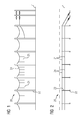
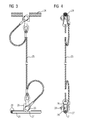
- FIG. 6 An inventive transport system comprises according to FIG. 6 .
- FIG. 8 and FIG. 10 a vehicle 10 which is not rail-bound, electric or hybrid-electric driven.
- the vehicle 10 designed as a diesel-electric truck has a driver's cab 11, a charging structure 12 arranged behind it and a current collector 13 supported therebetween for supplying electrical energy from a two-pole overhead line system 20 of the transport system.
- the overhead contact line system 20 has contact wires 21 which are designed as a forward and return conductor and run parallel to one another via a lane L of the vehicle 10, for instance above the right-hand lane of a multi-lane motorway.
- the overhead line system 20 side the lane L erected masts 22, from which boom 23 protrude laterally beyond the lane L.
- Above the lane L further two support cables 24, which are supported by the arms 23 and sag between them in a chain line.
- On each support cable 24 depending a contact wire 21 depends on a variety of hangers 25 whose lengths decrease with increasing distance from the arms, so that an approximately constant contact wire height above the lane L can be adjusted.
- a hanger rope 25 is attached to a contact wire 21 by means of a hanger clamp 26, the clamping edges 27 are held in a form-fitting manner by means of a screw 28 in each one of two longitudinal grooves 29 of the contact wire 21. This type of attachment ensures that the hanger clamps 26 do not present obstacles in the trimming of the contact wires 21 by the current collector 13 of the vehicle 10.
- the chain mechanism is braced by unspecified tensioning devices.
- the current collector 13 has two support arms 14, which carry a rocker assembly 15 with contact strips 16.
- the support arms 14 are rotatably mounted on the vehicle side about horizontal axes, whereby the rocker assembly 15 by means of a lifting device, not shown, between a lower rest position in which the current collector 13 is placed over the cab 11, and an upper working position in which the contact strips 16, the contact wires 21st contact, can be raised and lowered.
- the support arms 14 are rotatably mounted on the vehicle side about vertical axes, whereby the rocker assembly 15 by means not shown actuators laterally, ie transversely to a direction of travel V of the vehicle 10, is pivotable.
- a control device not shown, provided with a vehicle-mounted video detector 17 for determining a lateral relative position of the contact wires 21 is connected relative to the vehicle 10.
- the control device has a control unit, not shown, which calculates a manipulated variable for the actuators from the determined relative position and the current position of the rocker arrangement 15 in such a way that the contact strips 21 contact the contact wires 21 within their working range. Therefore, the control unit is connected to the actuators to transmit to this one of the calculated manipulated variable corresponding control signal.
- the actuators pivot the rocker assembly 15 by rotation of the support arms 14 about their vertical axes.
- the overhead contact line system 20 has the position of the contact wires 21 marking marking elements.
- the video detector 17 is designed for this purpose for recording video images of the marking elements.
- the video detector 17 is associated with an evaluation unit, not shown, which is adapted to detect from a recorded video image whether contact wires 21 are present above the vehicle 10, and in the presence of contact wires 21 to determine their relative position to the vehicle 10.
- the evaluation unit can be integrated, for example, in the video detector 17.
- the video detector 17 may be formed as a stereo camera for recording 3D images or as a runtime camera for distance measurement between the video detector 17 and a marking element.
- the video detector 17 may comprise an exposure unit, not shown, which is designed to emit infrared light in the direction of a detection axis 18 of the video detector 17.
- the marking elements are formed by angle pieces 31.
- An elbow 31 has a first leg with a preferably retroreflective reflective surface 32 and a second leg with a mounting interface 33 in the form of a slot.
- the angle pieces 31 are attached to the hanger clamps 26 of the contact wires 21 by their second leg is placed under a screw head of the screw 28.
- the second legs of the angle pieces 31 are aligned so that the normal of the reflection surface 32 are slightly inclined from the direction of travel V down.
- the detection axis 18 of the video detector 17 is aligned in the direction of travel V or at an acute angle to this, so that reflected light from the reflection surface 32, for example, light from vehicle headlights or infrared light of the exposure unit, is recorded by the video detector 17.
- the video detector 17 is disposed inside the cab 11 to avoid rain and dirt deterioration. Both for the driver of the vehicle 10 and for the evaluation unit of the video detector 17, the angle pieces 31 directly mark the course of a contact wire 21, which enables an improved determination of the relative position between the vehicle 10 and the contact wires 21.
- the marking elements are formed by elongated profile pieces 34. These have a roof-shaped cross section and a downwardly facing reflection surface 35 for incident light.
- the profile pieces 34 may be fastened, for example, to a tether running parallel to the contact wires 21 and / or to outriggers of the overhead contact line system 20, which in FIG FIG. 8 not shown separately.
- the profile pieces 34 are arranged in a fixed spatial relationship to the contact wires 21, so that the evaluation unit of the video detector 17 from the recorded video images from the position of the profile pieces 34 on the position of the contact wires 21 and thus to the relative position of the vehicle 10 to the Contact wires 21 can close.
- the profile pieces 34 may be arranged on the free side edges of the profile pieces 34 downwardly projecting shields.
- the profile pieces 34 are - as well as the angle pieces 31 of the first embodiment - made of plastic or light metal, in particular made of aluminum, to pressurize the catenary of the overhead line system 20 with the lowest possible additional load by marking elements.
- the marking elements on the lane L facing sides of masts 22 of the trolley 20 are attached.
- the video detector 17 is formed on passage of a mast 22 for measuring its distance to the marking element.
- the marker elements are preferably arranged at a lower level on the mast 22 than the video detector 17 on the vehicle 10.
- the detection axis 18 of the video detector 17 relative to the horizontal can be tilted downwards, which protects against dazzling light at low sun.
- the detection axis 18 of the here between the cab 11 and loading structure 12 arranged video detector 17 is oriented transversely to the direction of travel V, whereby impairments of the distance measurements and the image recordings are reduced by rain.
- the marking elements each have an optically readable coding surface 37 for location information, for example in the form of a so-called two-dimensional quick-response code.
- the evaluation unit is designed to read out from a recorded video image an information code represented by the coding surface 37. By means of the read-out information code, the evaluation unit queries the location information from a vehicle-side database or via wireless communication means from a vehicle-external database.
- the location information may include a current mast number and / or geographical mast coordinates, which allows the evaluation unit, in combination with the measured mast distance to close the relative position of the contact wires 21 to the vehicle 10.
- the location information may include information about the route, such as current hazard warnings such as black ice, oil or obstacles, traffic jams or bends on the upcoming leg that may be provided to a driver of the vehicle 10 via an audible and / or visual output interface.
- current hazard warnings such as black ice, oil or obstacles, traffic jams or bends on the upcoming leg that may be provided to a driver of the vehicle 10 via an audible and / or visual output interface.
- the evaluation unit can calculate the current relative position of the vehicle 10 relative to the contact wires 21, if appropriate with additional information about mast positions and distances to the mast. In this case, the use of cheaper stereo or time-of-flight cameras than video detectors 17 is possible even in bad weather conditions.
- the coupled to the evaluation unit control device of the current collector 13 controls the lifting device for lifting the rocker assembly 15 when the evaluation unit has detected the presence of the correct overhead line. It controls the actuators for lateral pivoting of the rocker assembly 15 when the evaluation unit has detected a relative position between the vehicle 10 and contact wires 21, which could lead to a threat of contact loss of the contact strips 16 to the contact wires. If the impending loss of contact can no longer be avoided by laterally tracking the current collector 13, then the control device controls the lifting device for lowering the rocker arrangement 15.
Landscapes
- Engineering & Computer Science (AREA)
- Mechanical Engineering (AREA)
- Power Engineering (AREA)
- Transportation (AREA)
- Current-Collector Devices For Electrically Propelled Vehicles (AREA)
Applications Claiming Priority (1)
| Application Number | Priority Date | Filing Date | Title |
|---|---|---|---|
| DE102014219466.0A DE102014219466A1 (de) | 2014-09-25 | 2014-09-25 | Transportsystem mit einem über eine Oberleitungsanlage mit elektrischer Energie versorgbaren, nicht schienengebundenen Fahrzeug |
Publications (2)
| Publication Number | Publication Date |
|---|---|
| EP3000644A1 true EP3000644A1 (fr) | 2016-03-30 |
| EP3000644B1 EP3000644B1 (fr) | 2020-06-03 |
Family
ID=54147043
Family Applications (1)
| Application Number | Title | Priority Date | Filing Date |
|---|---|---|---|
| EP15185210.0A Active EP3000644B1 (fr) | 2014-09-25 | 2015-09-15 | Systeme de transport dote d'un vehicule non relie par rails, pouvant etre alimente en energie electrique par une installation de catenaires |
Country Status (3)
| Country | Link |
|---|---|
| US (1) | US10023074B2 (fr) |
| EP (1) | EP3000644B1 (fr) |
| DE (1) | DE102014219466A1 (fr) |
Cited By (2)
| Publication number | Priority date | Publication date | Assignee | Title |
|---|---|---|---|---|
| WO2021189086A1 (fr) * | 2020-03-19 | 2021-09-23 | Transnet Soc Ltd | Dispositif indicateur visuel, système de surveillance du dispositif indicateur visuel et procédé associé |
| US20230050922A1 (en) * | 2020-01-15 | 2023-02-16 | Siemens Mobility GmbH | Road-guided motor vehicle and method for raising the pantograph of a power collector of a road-guided motor vehicle |
Families Citing this family (20)
| Publication number | Priority date | Publication date | Assignee | Title |
|---|---|---|---|---|
| US9283866B2 (en) * | 2012-01-31 | 2016-03-15 | Joy MM Deleware, Inc. | Overhead power grid for mobile mining machines |
| WO2017102029A1 (fr) * | 2015-12-18 | 2017-06-22 | Volvo Truck Corporation | Procédé de positionnement de véhicule à l'aide de système de route électrique, et véhicule fonctionnant à l'aide de ce procédé |
| DE102016205804A1 (de) * | 2016-04-07 | 2017-10-12 | Siemens Aktiengesellschaft | Positionsbestimmungssystem |
| ITUA20162698A1 (it) * | 2016-04-19 | 2017-10-19 | Mer Mec S P A | Sistema ottico per la misura della forza di contatto tra il pantografo e la catenaria |
| DE102016013065B4 (de) * | 2016-11-03 | 2022-07-28 | Henryk Bastian | Zusatzstromabnehmer für Schienenfahrzeuge mit Stromabnahme über eine Oberleitung |
| CN108773272A (zh) * | 2018-04-11 | 2018-11-09 | 徐州市彭宁机电科技有限公司 | 连杆超越装置 |
| DE102018208359B4 (de) | 2018-05-28 | 2024-06-06 | Volkswagen Aktiengesellschaft | Verfahren zum Verändern einer Position wenigstens einer Schleifleiste eines Stromabnehmers in Relation zu wenigstens einem Fahrdraht einer Oberleitung |
| SE543025C2 (en) * | 2019-06-13 | 2020-09-29 | Elonroad Ab | Method, control circuit and control system for guiding a sliding contact of a vehicle to collect electrical power |
| WO2021037351A1 (fr) * | 2019-08-28 | 2021-03-04 | Schunk Transit Systems Gmbh | Unité de positionnement et procédé de mise en contact |
| DE102019130349A1 (de) * | 2019-11-11 | 2021-05-12 | Kiepe Electric Gmbh | Stromabnehmersystem sowie Verfahren zum automatischen An- und/oder Abdrahten eines Stromabnehmersystems |
| CN111017247A (zh) * | 2019-12-13 | 2020-04-17 | 北京京东乾石科技有限公司 | 一种受电弓、供电系统和配送系统 |
| DE102020204566A1 (de) | 2020-04-08 | 2021-10-14 | Volkswagen Aktiengesellschaft | Koppelverfahren zum Koppeln eines Fahrzeugs mit einer Oberleitung, Computerprogrammprodukt sowie Fahrzeug |
| CN112297957B (zh) | 2020-09-08 | 2021-12-14 | 北京京东乾石科技有限公司 | 滑触线检测装置及滑触线检测系统 |
| DE202022102525U1 (de) | 2022-05-09 | 2023-08-10 | Hofer Powertrain Innovation Gmbh | Stromversorgungssystem für Kraftfahrzeuge, insbesondere Nutzfahrzeuge für elektrisch betriebenen Schwerverkehr |
| CN114734883B (zh) * | 2022-03-23 | 2023-07-04 | 中铁建电气化局集团第一工程有限公司 | 一种接触网吊弦智能安装系统 |
| CN119947920A (zh) * | 2022-06-30 | 2025-05-06 | 西门子交通有限公司 | 用于到公路车辆中的能量供应的能量供应系统 |
| DE102022208846A1 (de) * | 2022-08-26 | 2024-02-29 | Siemens Mobility GmbH | Straßenfahrzeug mit einem Stromabnehmer |
| US12552449B2 (en) * | 2023-01-19 | 2026-02-17 | Transportation Ip Holdings, Llc | Pantograph-based vehicle guidance system and method |
| CN118315987B (zh) * | 2024-02-26 | 2025-11-11 | 阜新聚森机械设备有限公司 | 一种铁路冰雪清除装置 |
| EP4714719A1 (fr) * | 2024-09-23 | 2026-03-25 | Bluvein Innovation Pty. Ltd. | Système et procédé d'alimentation électrique de véhicules électriques |
Citations (9)
| Publication number | Priority date | Publication date | Assignee | Title |
|---|---|---|---|---|
| US4070584A (en) * | 1974-12-20 | 1978-01-24 | Thomson-Csf | Object-identification system with sequentially activated photocell array |
| FR2540801A1 (fr) | 1983-02-15 | 1984-08-17 | Techno 2000 | Dispositif de commande de l'emperchage de trolleybus avec au moins une catenaire |
| GB2244581A (en) | 1990-06-02 | 1991-12-04 | Solvit Scient Engineers Limite | System to read barcode signs from or on a moving vehicle |
| DE102010053528A1 (de) | 2010-11-30 | 2012-05-31 | Dialogika Gesellschaft Für Angewandte Informatik Mbh | System für das automatische An- und Abdrahten während der Fahrt eines Oberleitungsfahrzeuges |
| DE102011076620A1 (de) * | 2011-05-27 | 2012-11-29 | Siemens Aktiengesellschaft | Nicht schienengebundenes Fahrzeug |
| DE102011076623A1 (de) | 2011-05-27 | 2012-11-29 | Siemens Ag | Nicht schienengebundenes Fahrzeug |
| DE102012205276A1 (de) | 2012-03-30 | 2013-10-02 | Siemens Aktiengesellschaft | Nicht schienengebundenes Fahrzeug |
| DE102012213460A1 (de) * | 2012-07-31 | 2014-02-06 | Siemens Aktiengesellschaft | Nicht schienengebundenes Fahrzeug |
| DE112012004019T5 (de) * | 2011-09-27 | 2014-07-17 | Hitachi Construction Machinery Co., Ltd. | Elektrisch angetriebener Kipp-Lastwagen |
Family Cites Families (2)
| Publication number | Priority date | Publication date | Assignee | Title |
|---|---|---|---|---|
| JP2005094952A (ja) * | 2003-09-18 | 2005-04-07 | Akira Nomura | 集電装置 |
| DE102012210519A1 (de) * | 2012-06-21 | 2013-12-24 | Siemens Aktiengesellschaft | Fahrzeug mit einer durch einen Fahrer bedienbaren und elektronisch gesteuerten Fahrzeugeinrichtung |
-
2014
- 2014-09-25 DE DE102014219466.0A patent/DE102014219466A1/de not_active Ceased
-
2015
- 2015-09-15 EP EP15185210.0A patent/EP3000644B1/fr active Active
- 2015-09-25 US US14/865,218 patent/US10023074B2/en active Active
Patent Citations (9)
| Publication number | Priority date | Publication date | Assignee | Title |
|---|---|---|---|---|
| US4070584A (en) * | 1974-12-20 | 1978-01-24 | Thomson-Csf | Object-identification system with sequentially activated photocell array |
| FR2540801A1 (fr) | 1983-02-15 | 1984-08-17 | Techno 2000 | Dispositif de commande de l'emperchage de trolleybus avec au moins une catenaire |
| GB2244581A (en) | 1990-06-02 | 1991-12-04 | Solvit Scient Engineers Limite | System to read barcode signs from or on a moving vehicle |
| DE102010053528A1 (de) | 2010-11-30 | 2012-05-31 | Dialogika Gesellschaft Für Angewandte Informatik Mbh | System für das automatische An- und Abdrahten während der Fahrt eines Oberleitungsfahrzeuges |
| DE102011076620A1 (de) * | 2011-05-27 | 2012-11-29 | Siemens Aktiengesellschaft | Nicht schienengebundenes Fahrzeug |
| DE102011076623A1 (de) | 2011-05-27 | 2012-11-29 | Siemens Ag | Nicht schienengebundenes Fahrzeug |
| DE112012004019T5 (de) * | 2011-09-27 | 2014-07-17 | Hitachi Construction Machinery Co., Ltd. | Elektrisch angetriebener Kipp-Lastwagen |
| DE102012205276A1 (de) | 2012-03-30 | 2013-10-02 | Siemens Aktiengesellschaft | Nicht schienengebundenes Fahrzeug |
| DE102012213460A1 (de) * | 2012-07-31 | 2014-02-06 | Siemens Aktiengesellschaft | Nicht schienengebundenes Fahrzeug |
Cited By (3)
| Publication number | Priority date | Publication date | Assignee | Title |
|---|---|---|---|---|
| US20230050922A1 (en) * | 2020-01-15 | 2023-02-16 | Siemens Mobility GmbH | Road-guided motor vehicle and method for raising the pantograph of a power collector of a road-guided motor vehicle |
| US12545117B2 (en) * | 2020-01-15 | 2026-02-10 | Siemens Mobility GmbH | Road-guided motor vehicle and method for raising the pantograph of a power collector of a road-guided motor vehicle |
| WO2021189086A1 (fr) * | 2020-03-19 | 2021-09-23 | Transnet Soc Ltd | Dispositif indicateur visuel, système de surveillance du dispositif indicateur visuel et procédé associé |
Also Published As
| Publication number | Publication date |
|---|---|
| US10023074B2 (en) | 2018-07-17 |
| US20160090007A1 (en) | 2016-03-31 |
| DE102014219466A1 (de) | 2016-03-31 |
| EP3000644B1 (fr) | 2020-06-03 |
Similar Documents
| Publication | Publication Date | Title |
|---|---|---|
| EP3000644B1 (fr) | Systeme de transport dote d'un vehicule non relie par rails, pouvant etre alimente en energie electrique par une installation de catenaires | |
| EP2644432B1 (fr) | Véhicule ne roulant pas sur rails | |
| EP2714457B1 (fr) | Véhicule non ferroviaire | |
| DE60123936T2 (de) | Einrichtung zum erkennen der anwesenheit von objekten | |
| EP3266638A1 (fr) | Commande automatisée d'une voie de circulation théorique destinée à l'alimentation continue en énergie électrique | |
| WO2012163763A2 (fr) | Véhicule non ferroviaire | |
| DE102011076620A1 (de) | Nicht schienengebundenes Fahrzeug | |
| DE102012213460A1 (de) | Nicht schienengebundenes Fahrzeug | |
| DE102009013841A1 (de) | Messsystem für die Verkehrsstromanalyse | |
| DE102015213071A1 (de) | Infrastrukturgestützte Detektion von Fahrleitungen | |
| EP4063171A1 (fr) | Collecteur de courant, ainsi que véhicule routier doté d'un tel collecteur de courant | |
| DE102008048827A1 (de) | Spurführungssystem | |
| DE19940350C2 (de) | Verfahren und Anordnung zur Überwachung des Fahrdrahtes einer Fahrtstrecke für elektrisch antreibbare Schienenfahrzeuge | |
| EP4143808B1 (fr) | Système d'assistance pour un véhicule routier | |
| DE102017215226B4 (de) | Verfahren zur Navigation eines straßengebundenen Kraftfahrzeugs mit einem Stromabnehmer | |
| DE102009018763A1 (de) | Verfahren zur Erfassung von Bauteilen in Oberleitungsanlagen von Schienenfahrzeugen, insbesondere von Eisenbahnfahrzeugen | |
| DE102017213282A1 (de) | Verfahren sowie Detektionssystem zur Überprüfung einer Position eines elektromotorisch angetriebenen Kraftfahrzeugs | |
| WO2023151765A1 (fr) | Procédé de génération d'une instruction de conduite pour un véhicule et agencement d'infrastructure | |
| EP4269169B1 (fr) | Procédé de détection de l'état d'une installation de caténaire côté route | |
| DE102015216421A1 (de) | Vorrichtung zur Detektion eines Fahrdrahtes | |
| EP2827047B1 (fr) | Installation d'éclairage destiné à marquer une voie de circulation d'une chaussée | |
| DE102019134191A1 (de) | Umlenkspiegeleinrichtung für eine optische Detektionsvorrichtung und optische Detektionsvorrichtung | |
| DE102022208846A1 (de) | Straßenfahrzeug mit einem Stromabnehmer | |
| DE3941887C2 (fr) | ||
| DE102022207793A1 (de) | Zustandsüberwachungssystem mit verfahrbarer Sensoreinrichtung |
Legal Events
| Date | Code | Title | Description |
|---|---|---|---|
| PUAI | Public reference made under article 153(3) epc to a published international application that has entered the european phase |
Free format text: ORIGINAL CODE: 0009012 |
|
| AK | Designated contracting states |
Kind code of ref document: A1 Designated state(s): AL AT BE BG CH CY CZ DE DK EE ES FI FR GB GR HR HU IE IS IT LI LT LU LV MC MK MT NL NO PL PT RO RS SE SI SK SM TR |
|
| AX | Request for extension of the european patent |
Extension state: BA ME |
|
| STAA | Information on the status of an ep patent application or granted ep patent |
Free format text: STATUS: THE APPLICATION HAS BEEN PUBLISHED |
|
| STAA | Information on the status of an ep patent application or granted ep patent |
Free format text: STATUS: REQUEST FOR EXAMINATION WAS MADE |
|
| 17P | Request for examination filed |
Effective date: 20170117 |
|
| RBV | Designated contracting states (corrected) |
Designated state(s): AL AT BE BG CH CY CZ DE DK EE ES FI FR GB GR HR HU IE IS IT LI LT LU LV MC MK MT NL NO PL PT RO RS SE SI SK SM TR |
|
| RAP1 | Party data changed (applicant data changed or rights of an application transferred) |
Owner name: SIEMENS AKTIENGESELLSCHAFT |
|
| STAA | Information on the status of an ep patent application or granted ep patent |
Free format text: STATUS: EXAMINATION IS IN PROGRESS |
|
| 17Q | First examination report despatched |
Effective date: 20180919 |
|
| RAP1 | Party data changed (applicant data changed or rights of an application transferred) |
Owner name: SIEMENS MOBILITY GMBH |
|
| REG | Reference to a national code |
Ref country code: DE Ref legal event code: R079 Ref document number: 502015012692 Country of ref document: DE Free format text: PREVIOUS MAIN CLASS: B60L0005040000 Ipc: B60M0001230000 |
|
| GRAP | Despatch of communication of intention to grant a patent |
Free format text: ORIGINAL CODE: EPIDOSNIGR1 |
|
| STAA | Information on the status of an ep patent application or granted ep patent |
Free format text: STATUS: GRANT OF PATENT IS INTENDED |
|
| RIC1 | Information provided on ipc code assigned before grant |
Ipc: B60M 1/12 20060101ALI20200115BHEP Ipc: B60L 5/36 20060101ALI20200115BHEP Ipc: B60L 5/04 20060101ALI20200115BHEP Ipc: B60M 1/23 20060101AFI20200115BHEP |
|
| INTG | Intention to grant announced |
Effective date: 20200205 |
|
| GRAS | Grant fee paid |
Free format text: ORIGINAL CODE: EPIDOSNIGR3 |
|
| GRAA | (expected) grant |
Free format text: ORIGINAL CODE: 0009210 |
|
| STAA | Information on the status of an ep patent application or granted ep patent |
Free format text: STATUS: THE PATENT HAS BEEN GRANTED |
|
| AK | Designated contracting states |
Kind code of ref document: B1 Designated state(s): AL AT BE BG CH CY CZ DE DK EE ES FI FR GB GR HR HU IE IS IT LI LT LU LV MC MK MT NL NO PL PT RO RS SE SI SK SM TR |
|
| REG | Reference to a national code |
Ref country code: GB Ref legal event code: FG4D Free format text: NOT ENGLISH |
|
| REG | Reference to a national code |
Ref country code: CH Ref legal event code: EP Ref country code: AT Ref legal event code: REF Ref document number: 1276688 Country of ref document: AT Kind code of ref document: T Effective date: 20200615 |
|
| REG | Reference to a national code |
Ref country code: DE Ref legal event code: R096 Ref document number: 502015012692 Country of ref document: DE |
|
| REG | Reference to a national code |
Ref country code: LT Ref legal event code: MG4D |
|
| PG25 | Lapsed in a contracting state [announced via postgrant information from national office to epo] |
Ref country code: SE Free format text: LAPSE BECAUSE OF FAILURE TO SUBMIT A TRANSLATION OF THE DESCRIPTION OR TO PAY THE FEE WITHIN THE PRESCRIBED TIME-LIMIT Effective date: 20200603 Ref country code: GR Free format text: LAPSE BECAUSE OF FAILURE TO SUBMIT A TRANSLATION OF THE DESCRIPTION OR TO PAY THE FEE WITHIN THE PRESCRIBED TIME-LIMIT Effective date: 20200904 Ref country code: NO Free format text: LAPSE BECAUSE OF FAILURE TO SUBMIT A TRANSLATION OF THE DESCRIPTION OR TO PAY THE FEE WITHIN THE PRESCRIBED TIME-LIMIT Effective date: 20200903 Ref country code: FI Free format text: LAPSE BECAUSE OF FAILURE TO SUBMIT A TRANSLATION OF THE DESCRIPTION OR TO PAY THE FEE WITHIN THE PRESCRIBED TIME-LIMIT Effective date: 20200603 Ref country code: LT Free format text: LAPSE BECAUSE OF FAILURE TO SUBMIT A TRANSLATION OF THE DESCRIPTION OR TO PAY THE FEE WITHIN THE PRESCRIBED TIME-LIMIT Effective date: 20200603 |
|
| REG | Reference to a national code |
Ref country code: NL Ref legal event code: MP Effective date: 20200603 |
|
| PG25 | Lapsed in a contracting state [announced via postgrant information from national office to epo] |
Ref country code: LV Free format text: LAPSE BECAUSE OF FAILURE TO SUBMIT A TRANSLATION OF THE DESCRIPTION OR TO PAY THE FEE WITHIN THE PRESCRIBED TIME-LIMIT Effective date: 20200603 Ref country code: BG Free format text: LAPSE BECAUSE OF FAILURE TO SUBMIT A TRANSLATION OF THE DESCRIPTION OR TO PAY THE FEE WITHIN THE PRESCRIBED TIME-LIMIT Effective date: 20200903 Ref country code: RS Free format text: LAPSE BECAUSE OF FAILURE TO SUBMIT A TRANSLATION OF THE DESCRIPTION OR TO PAY THE FEE WITHIN THE PRESCRIBED TIME-LIMIT Effective date: 20200603 Ref country code: HR Free format text: LAPSE BECAUSE OF FAILURE TO SUBMIT A TRANSLATION OF THE DESCRIPTION OR TO PAY THE FEE WITHIN THE PRESCRIBED TIME-LIMIT Effective date: 20200603 |
|
| PG25 | Lapsed in a contracting state [announced via postgrant information from national office to epo] |
Ref country code: NL Free format text: LAPSE BECAUSE OF FAILURE TO SUBMIT A TRANSLATION OF THE DESCRIPTION OR TO PAY THE FEE WITHIN THE PRESCRIBED TIME-LIMIT Effective date: 20200603 Ref country code: AL Free format text: LAPSE BECAUSE OF FAILURE TO SUBMIT A TRANSLATION OF THE DESCRIPTION OR TO PAY THE FEE WITHIN THE PRESCRIBED TIME-LIMIT Effective date: 20200603 |
|
| PG25 | Lapsed in a contracting state [announced via postgrant information from national office to epo] |
Ref country code: EE Free format text: LAPSE BECAUSE OF FAILURE TO SUBMIT A TRANSLATION OF THE DESCRIPTION OR TO PAY THE FEE WITHIN THE PRESCRIBED TIME-LIMIT Effective date: 20200603 Ref country code: IT Free format text: LAPSE BECAUSE OF FAILURE TO SUBMIT A TRANSLATION OF THE DESCRIPTION OR TO PAY THE FEE WITHIN THE PRESCRIBED TIME-LIMIT Effective date: 20200603 Ref country code: SM Free format text: LAPSE BECAUSE OF FAILURE TO SUBMIT A TRANSLATION OF THE DESCRIPTION OR TO PAY THE FEE WITHIN THE PRESCRIBED TIME-LIMIT Effective date: 20200603 Ref country code: PT Free format text: LAPSE BECAUSE OF FAILURE TO SUBMIT A TRANSLATION OF THE DESCRIPTION OR TO PAY THE FEE WITHIN THE PRESCRIBED TIME-LIMIT Effective date: 20201006 Ref country code: ES Free format text: LAPSE BECAUSE OF FAILURE TO SUBMIT A TRANSLATION OF THE DESCRIPTION OR TO PAY THE FEE WITHIN THE PRESCRIBED TIME-LIMIT Effective date: 20200603 Ref country code: CZ Free format text: LAPSE BECAUSE OF FAILURE TO SUBMIT A TRANSLATION OF THE DESCRIPTION OR TO PAY THE FEE WITHIN THE PRESCRIBED TIME-LIMIT Effective date: 20200603 Ref country code: RO Free format text: LAPSE BECAUSE OF FAILURE TO SUBMIT A TRANSLATION OF THE DESCRIPTION OR TO PAY THE FEE WITHIN THE PRESCRIBED TIME-LIMIT Effective date: 20200603 |
|
| PG25 | Lapsed in a contracting state [announced via postgrant information from national office to epo] |
Ref country code: PL Free format text: LAPSE BECAUSE OF FAILURE TO SUBMIT A TRANSLATION OF THE DESCRIPTION OR TO PAY THE FEE WITHIN THE PRESCRIBED TIME-LIMIT Effective date: 20200603 Ref country code: SK Free format text: LAPSE BECAUSE OF FAILURE TO SUBMIT A TRANSLATION OF THE DESCRIPTION OR TO PAY THE FEE WITHIN THE PRESCRIBED TIME-LIMIT Effective date: 20200603 Ref country code: IS Free format text: LAPSE BECAUSE OF FAILURE TO SUBMIT A TRANSLATION OF THE DESCRIPTION OR TO PAY THE FEE WITHIN THE PRESCRIBED TIME-LIMIT Effective date: 20201003 |
|
| REG | Reference to a national code |
Ref country code: DE Ref legal event code: R097 Ref document number: 502015012692 Country of ref document: DE |
|
| PLBE | No opposition filed within time limit |
Free format text: ORIGINAL CODE: 0009261 |
|
| STAA | Information on the status of an ep patent application or granted ep patent |
Free format text: STATUS: NO OPPOSITION FILED WITHIN TIME LIMIT |
|
| PG25 | Lapsed in a contracting state [announced via postgrant information from national office to epo] |
Ref country code: DK Free format text: LAPSE BECAUSE OF FAILURE TO SUBMIT A TRANSLATION OF THE DESCRIPTION OR TO PAY THE FEE WITHIN THE PRESCRIBED TIME-LIMIT Effective date: 20200603 Ref country code: MC Free format text: LAPSE BECAUSE OF FAILURE TO SUBMIT A TRANSLATION OF THE DESCRIPTION OR TO PAY THE FEE WITHIN THE PRESCRIBED TIME-LIMIT Effective date: 20200603 |
|
| REG | Reference to a national code |
Ref country code: CH Ref legal event code: PL |
|
| 26N | No opposition filed |
Effective date: 20210304 |
|
| GBPC | Gb: european patent ceased through non-payment of renewal fee |
Effective date: 20200915 |
|
| PG25 | Lapsed in a contracting state [announced via postgrant information from national office to epo] |
Ref country code: SI Free format text: LAPSE BECAUSE OF FAILURE TO SUBMIT A TRANSLATION OF THE DESCRIPTION OR TO PAY THE FEE WITHIN THE PRESCRIBED TIME-LIMIT Effective date: 20200603 |
|
| REG | Reference to a national code |
Ref country code: BE Ref legal event code: MM Effective date: 20200930 |
|
| PG25 | Lapsed in a contracting state [announced via postgrant information from national office to epo] |
Ref country code: LU Free format text: LAPSE BECAUSE OF NON-PAYMENT OF DUE FEES Effective date: 20200915 |
|
| PG25 | Lapsed in a contracting state [announced via postgrant information from national office to epo] |
Ref country code: FR Free format text: LAPSE BECAUSE OF NON-PAYMENT OF DUE FEES Effective date: 20200930 |
|
| PG25 | Lapsed in a contracting state [announced via postgrant information from national office to epo] |
Ref country code: CH Free format text: LAPSE BECAUSE OF NON-PAYMENT OF DUE FEES Effective date: 20200930 Ref country code: BE Free format text: LAPSE BECAUSE OF NON-PAYMENT OF DUE FEES Effective date: 20200930 Ref country code: GB Free format text: LAPSE BECAUSE OF NON-PAYMENT OF DUE FEES Effective date: 20200915 Ref country code: LI Free format text: LAPSE BECAUSE OF NON-PAYMENT OF DUE FEES Effective date: 20200930 Ref country code: IE Free format text: LAPSE BECAUSE OF NON-PAYMENT OF DUE FEES Effective date: 20200915 |
|
| REG | Reference to a national code |
Ref country code: AT Ref legal event code: MM01 Ref document number: 1276688 Country of ref document: AT Kind code of ref document: T Effective date: 20200915 |
|
| PG25 | Lapsed in a contracting state [announced via postgrant information from national office to epo] |
Ref country code: AT Free format text: LAPSE BECAUSE OF NON-PAYMENT OF DUE FEES Effective date: 20200915 |
|
| PG25 | Lapsed in a contracting state [announced via postgrant information from national office to epo] |
Ref country code: TR Free format text: LAPSE BECAUSE OF FAILURE TO SUBMIT A TRANSLATION OF THE DESCRIPTION OR TO PAY THE FEE WITHIN THE PRESCRIBED TIME-LIMIT Effective date: 20200603 Ref country code: MT Free format text: LAPSE BECAUSE OF FAILURE TO SUBMIT A TRANSLATION OF THE DESCRIPTION OR TO PAY THE FEE WITHIN THE PRESCRIBED TIME-LIMIT Effective date: 20200603 Ref country code: CY Free format text: LAPSE BECAUSE OF FAILURE TO SUBMIT A TRANSLATION OF THE DESCRIPTION OR TO PAY THE FEE WITHIN THE PRESCRIBED TIME-LIMIT Effective date: 20200603 |
|
| PG25 | Lapsed in a contracting state [announced via postgrant information from national office to epo] |
Ref country code: MK Free format text: LAPSE BECAUSE OF FAILURE TO SUBMIT A TRANSLATION OF THE DESCRIPTION OR TO PAY THE FEE WITHIN THE PRESCRIBED TIME-LIMIT Effective date: 20200603 |
|
| PGFP | Annual fee paid to national office [announced via postgrant information from national office to epo] |
Ref country code: DE Payment date: 20231120 Year of fee payment: 9 |
|
| REG | Reference to a national code |
Ref country code: DE Ref legal event code: R119 Ref document number: 502015012692 Country of ref document: DE |
|
| PG25 | Lapsed in a contracting state [announced via postgrant information from national office to epo] |
Ref country code: DE Free format text: LAPSE BECAUSE OF NON-PAYMENT OF DUE FEES Effective date: 20250401 |