EP3000648A1 - Dispositif pour commander une automobile electrique - Google Patents
Dispositif pour commander une automobile electrique Download PDFInfo
- Publication number
- EP3000648A1 EP3000648A1 EP14800264.5A EP14800264A EP3000648A1 EP 3000648 A1 EP3000648 A1 EP 3000648A1 EP 14800264 A EP14800264 A EP 14800264A EP 3000648 A1 EP3000648 A1 EP 3000648A1
- Authority
- EP
- European Patent Office
- Prior art keywords
- control
- motor
- gain
- current
- command
- Prior art date
- Legal status (The legal status is an assumption and is not a legal conclusion. Google has not performed a legal analysis and makes no representation as to the accuracy of the status listed.)
- Withdrawn
Links
- 230000001172 regenerating effect Effects 0.000 claims abstract description 43
- 230000004044 response Effects 0.000 claims abstract description 7
- 230000003247 decreasing effect Effects 0.000 claims description 9
- 230000007423 decrease Effects 0.000 claims description 7
- 230000004043 responsiveness Effects 0.000 abstract description 14
- 230000006872 improvement Effects 0.000 abstract description 12
- 238000010586 diagram Methods 0.000 description 14
- 239000003638 chemical reducing agent Substances 0.000 description 13
- 238000006243 chemical reaction Methods 0.000 description 7
- 230000008929 regeneration Effects 0.000 description 6
- 238000011069 regeneration method Methods 0.000 description 6
- 230000005856 abnormality Effects 0.000 description 5
- 238000000034 method Methods 0.000 description 5
- 230000001133 acceleration Effects 0.000 description 3
- 230000006866 deterioration Effects 0.000 description 3
- 238000004891 communication Methods 0.000 description 2
- 238000001514 detection method Methods 0.000 description 2
- 230000006870 function Effects 0.000 description 2
- 238000012986 modification Methods 0.000 description 2
- 230000004048 modification Effects 0.000 description 2
- 230000009467 reduction Effects 0.000 description 2
- 239000004065 semiconductor Substances 0.000 description 2
- 230000001629 suppression Effects 0.000 description 2
- 238000010276 construction Methods 0.000 description 1
- 230000000694 effects Effects 0.000 description 1
- 230000007246 mechanism Effects 0.000 description 1
- 230000001360 synchronised effect Effects 0.000 description 1
Images





Classifications
-
- B—PERFORMING OPERATIONS; TRANSPORTING
- B60—VEHICLES IN GENERAL
- B60L—PROPULSION OF ELECTRICALLY-PROPELLED VEHICLES; SUPPLYING ELECTRIC POWER FOR AUXILIARY EQUIPMENT OF ELECTRICALLY-PROPELLED VEHICLES; ELECTRODYNAMIC BRAKE SYSTEMS FOR VEHICLES IN GENERAL; MAGNETIC SUSPENSION OR LEVITATION FOR VEHICLES; MONITORING OPERATING VARIABLES OF ELECTRICALLY-PROPELLED VEHICLES; ELECTRIC SAFETY DEVICES FOR ELECTRICALLY-PROPELLED VEHICLES
- B60L15/00—Methods, circuits, or devices for controlling the traction-motor speed of electrically-propelled vehicles
- B60L15/20—Methods, circuits, or devices for controlling the traction-motor speed of electrically-propelled vehicles for control of the vehicle or its driving motor to achieve a desired performance, e.g. speed, torque, programmed variation of speed
- B60L15/2045—Methods, circuits, or devices for controlling the traction-motor speed of electrically-propelled vehicles for control of the vehicle or its driving motor to achieve a desired performance, e.g. speed, torque, programmed variation of speed for optimising the use of energy
-
- B—PERFORMING OPERATIONS; TRANSPORTING
- B60—VEHICLES IN GENERAL
- B60L—PROPULSION OF ELECTRICALLY-PROPELLED VEHICLES; SUPPLYING ELECTRIC POWER FOR AUXILIARY EQUIPMENT OF ELECTRICALLY-PROPELLED VEHICLES; ELECTRODYNAMIC BRAKE SYSTEMS FOR VEHICLES IN GENERAL; MAGNETIC SUSPENSION OR LEVITATION FOR VEHICLES; MONITORING OPERATING VARIABLES OF ELECTRICALLY-PROPELLED VEHICLES; ELECTRIC SAFETY DEVICES FOR ELECTRICALLY-PROPELLED VEHICLES
- B60L15/00—Methods, circuits, or devices for controlling the traction-motor speed of electrically-propelled vehicles
- B60L15/02—Methods, circuits, or devices for controlling the traction-motor speed of electrically-propelled vehicles characterised by the form of the current used in the control circuit
-
- B—PERFORMING OPERATIONS; TRANSPORTING
- B60—VEHICLES IN GENERAL
- B60L—PROPULSION OF ELECTRICALLY-PROPELLED VEHICLES; SUPPLYING ELECTRIC POWER FOR AUXILIARY EQUIPMENT OF ELECTRICALLY-PROPELLED VEHICLES; ELECTRODYNAMIC BRAKE SYSTEMS FOR VEHICLES IN GENERAL; MAGNETIC SUSPENSION OR LEVITATION FOR VEHICLES; MONITORING OPERATING VARIABLES OF ELECTRICALLY-PROPELLED VEHICLES; ELECTRIC SAFETY DEVICES FOR ELECTRICALLY-PROPELLED VEHICLES
- B60L15/00—Methods, circuits, or devices for controlling the traction-motor speed of electrically-propelled vehicles
- B60L15/02—Methods, circuits, or devices for controlling the traction-motor speed of electrically-propelled vehicles characterised by the form of the current used in the control circuit
- B60L15/025—Methods, circuits, or devices for controlling the traction-motor speed of electrically-propelled vehicles characterised by the form of the current used in the control circuit using field orientation; Vector control; Direct Torque Control [DTC]
-
- B—PERFORMING OPERATIONS; TRANSPORTING
- B60—VEHICLES IN GENERAL
- B60L—PROPULSION OF ELECTRICALLY-PROPELLED VEHICLES; SUPPLYING ELECTRIC POWER FOR AUXILIARY EQUIPMENT OF ELECTRICALLY-PROPELLED VEHICLES; ELECTRODYNAMIC BRAKE SYSTEMS FOR VEHICLES IN GENERAL; MAGNETIC SUSPENSION OR LEVITATION FOR VEHICLES; MONITORING OPERATING VARIABLES OF ELECTRICALLY-PROPELLED VEHICLES; ELECTRIC SAFETY DEVICES FOR ELECTRICALLY-PROPELLED VEHICLES
- B60L15/00—Methods, circuits, or devices for controlling the traction-motor speed of electrically-propelled vehicles
- B60L15/20—Methods, circuits, or devices for controlling the traction-motor speed of electrically-propelled vehicles for control of the vehicle or its driving motor to achieve a desired performance, e.g. speed, torque, programmed variation of speed
-
- B—PERFORMING OPERATIONS; TRANSPORTING
- B60—VEHICLES IN GENERAL
- B60L—PROPULSION OF ELECTRICALLY-PROPELLED VEHICLES; SUPPLYING ELECTRIC POWER FOR AUXILIARY EQUIPMENT OF ELECTRICALLY-PROPELLED VEHICLES; ELECTRODYNAMIC BRAKE SYSTEMS FOR VEHICLES IN GENERAL; MAGNETIC SUSPENSION OR LEVITATION FOR VEHICLES; MONITORING OPERATING VARIABLES OF ELECTRICALLY-PROPELLED VEHICLES; ELECTRIC SAFETY DEVICES FOR ELECTRICALLY-PROPELLED VEHICLES
- B60L7/00—Electrodynamic brake systems for vehicles in general
- B60L7/10—Dynamic electric regenerative braking
-
- G—PHYSICS
- G05—CONTROLLING; REGULATING
- G05B—CONTROL OR REGULATING SYSTEMS IN GENERAL; FUNCTIONAL ELEMENTS OF SUCH SYSTEMS; MONITORING OR TESTING ARRANGEMENTS FOR SUCH SYSTEMS OR ELEMENTS
- G05B11/00—Automatic controllers
- G05B11/01—Automatic controllers electric
- G05B11/36—Automatic controllers electric with provision for obtaining particular characteristics, e.g. proportional, integral, differential
- G05B11/42—Automatic controllers electric with provision for obtaining particular characteristics, e.g. proportional, integral, differential for obtaining a characteristic which is both proportional and time-dependent, e.g. P. I., P. I. D.
-
- H—ELECTRICITY
- H02—GENERATION; CONVERSION OR DISTRIBUTION OF ELECTRIC POWER
- H02P—CONTROL OR REGULATION OF ELECTRIC MOTORS, ELECTRIC GENERATORS OR DYNAMO-ELECTRIC CONVERTERS; CONTROLLING TRANSFORMERS, REACTORS OR CHOKE COILS
- H02P23/00—Arrangements or methods for the control of AC motors characterised by a control method other than vector control
- H02P23/0004—Control strategies in general, e.g. linear type, e.g. P, PI, PID, using robust control
-
- B—PERFORMING OPERATIONS; TRANSPORTING
- B60—VEHICLES IN GENERAL
- B60L—PROPULSION OF ELECTRICALLY-PROPELLED VEHICLES; SUPPLYING ELECTRIC POWER FOR AUXILIARY EQUIPMENT OF ELECTRICALLY-PROPELLED VEHICLES; ELECTRODYNAMIC BRAKE SYSTEMS FOR VEHICLES IN GENERAL; MAGNETIC SUSPENSION OR LEVITATION FOR VEHICLES; MONITORING OPERATING VARIABLES OF ELECTRICALLY-PROPELLED VEHICLES; ELECTRIC SAFETY DEVICES FOR ELECTRICALLY-PROPELLED VEHICLES
- B60L2240/00—Control parameters of input or output; Target parameters
- B60L2240/10—Vehicle control parameters
- B60L2240/12—Speed
-
- B—PERFORMING OPERATIONS; TRANSPORTING
- B60—VEHICLES IN GENERAL
- B60L—PROPULSION OF ELECTRICALLY-PROPELLED VEHICLES; SUPPLYING ELECTRIC POWER FOR AUXILIARY EQUIPMENT OF ELECTRICALLY-PROPELLED VEHICLES; ELECTRODYNAMIC BRAKE SYSTEMS FOR VEHICLES IN GENERAL; MAGNETIC SUSPENSION OR LEVITATION FOR VEHICLES; MONITORING OPERATING VARIABLES OF ELECTRICALLY-PROPELLED VEHICLES; ELECTRIC SAFETY DEVICES FOR ELECTRICALLY-PROPELLED VEHICLES
- B60L2240/00—Control parameters of input or output; Target parameters
- B60L2240/40—Drive Train control parameters
- B60L2240/42—Drive Train control parameters related to electric machines
- B60L2240/421—Speed
-
- B—PERFORMING OPERATIONS; TRANSPORTING
- B60—VEHICLES IN GENERAL
- B60L—PROPULSION OF ELECTRICALLY-PROPELLED VEHICLES; SUPPLYING ELECTRIC POWER FOR AUXILIARY EQUIPMENT OF ELECTRICALLY-PROPELLED VEHICLES; ELECTRODYNAMIC BRAKE SYSTEMS FOR VEHICLES IN GENERAL; MAGNETIC SUSPENSION OR LEVITATION FOR VEHICLES; MONITORING OPERATING VARIABLES OF ELECTRICALLY-PROPELLED VEHICLES; ELECTRIC SAFETY DEVICES FOR ELECTRICALLY-PROPELLED VEHICLES
- B60L2240/00—Control parameters of input or output; Target parameters
- B60L2240/40—Drive Train control parameters
- B60L2240/42—Drive Train control parameters related to electric machines
- B60L2240/423—Torque
-
- B—PERFORMING OPERATIONS; TRANSPORTING
- B60—VEHICLES IN GENERAL
- B60L—PROPULSION OF ELECTRICALLY-PROPELLED VEHICLES; SUPPLYING ELECTRIC POWER FOR AUXILIARY EQUIPMENT OF ELECTRICALLY-PROPELLED VEHICLES; ELECTRODYNAMIC BRAKE SYSTEMS FOR VEHICLES IN GENERAL; MAGNETIC SUSPENSION OR LEVITATION FOR VEHICLES; MONITORING OPERATING VARIABLES OF ELECTRICALLY-PROPELLED VEHICLES; ELECTRIC SAFETY DEVICES FOR ELECTRICALLY-PROPELLED VEHICLES
- B60L2240/00—Control parameters of input or output; Target parameters
- B60L2240/40—Drive Train control parameters
- B60L2240/42—Drive Train control parameters related to electric machines
- B60L2240/429—Current
-
- B—PERFORMING OPERATIONS; TRANSPORTING
- B60—VEHICLES IN GENERAL
- B60L—PROPULSION OF ELECTRICALLY-PROPELLED VEHICLES; SUPPLYING ELECTRIC POWER FOR AUXILIARY EQUIPMENT OF ELECTRICALLY-PROPELLED VEHICLES; ELECTRODYNAMIC BRAKE SYSTEMS FOR VEHICLES IN GENERAL; MAGNETIC SUSPENSION OR LEVITATION FOR VEHICLES; MONITORING OPERATING VARIABLES OF ELECTRICALLY-PROPELLED VEHICLES; ELECTRIC SAFETY DEVICES FOR ELECTRICALLY-PROPELLED VEHICLES
- B60L2260/00—Operating Modes
- B60L2260/40—Control modes
- B60L2260/42—Control modes by adaptive correction
-
- Y—GENERAL TAGGING OF NEW TECHNOLOGICAL DEVELOPMENTS; GENERAL TAGGING OF CROSS-SECTIONAL TECHNOLOGIES SPANNING OVER SEVERAL SECTIONS OF THE IPC; TECHNICAL SUBJECTS COVERED BY FORMER USPC CROSS-REFERENCE ART COLLECTIONS [XRACs] AND DIGESTS
- Y02—TECHNOLOGIES OR APPLICATIONS FOR MITIGATION OR ADAPTATION AGAINST CLIMATE CHANGE
- Y02T—CLIMATE CHANGE MITIGATION TECHNOLOGIES RELATED TO TRANSPORTATION
- Y02T10/00—Road transport of goods or passengers
- Y02T10/60—Other road transportation technologies with climate change mitigation effect
- Y02T10/64—Electric machine technologies in electromobility
-
- Y—GENERAL TAGGING OF NEW TECHNOLOGICAL DEVELOPMENTS; GENERAL TAGGING OF CROSS-SECTIONAL TECHNOLOGIES SPANNING OVER SEVERAL SECTIONS OF THE IPC; TECHNICAL SUBJECTS COVERED BY FORMER USPC CROSS-REFERENCE ART COLLECTIONS [XRACs] AND DIGESTS
- Y02—TECHNOLOGIES OR APPLICATIONS FOR MITIGATION OR ADAPTATION AGAINST CLIMATE CHANGE
- Y02T—CLIMATE CHANGE MITIGATION TECHNOLOGIES RELATED TO TRANSPORTATION
- Y02T10/00—Road transport of goods or passengers
- Y02T10/60—Other road transportation technologies with climate change mitigation effect
- Y02T10/72—Electric energy management in electromobility
Definitions
- the present invention relates to, for example, a control device for a four-wheel electric vehicle including an in-wheel motor drive device, and particularly relates to a technique to automatically adjust a motor control gain, thereby suppressing overshoot in torque control, improving motor responsiveness, and also reducing vibration of a cycloidal reducer disposed between a wheel bearing and a motor.
- an electric vehicle which includes, as drive wheels, right and left wheels driven by independent traction motors, respectively (Patent Document 1).
- Rotation of each motor is transmitted via a reducer or reduction gear and a wheel bearing to the corresponding wheel.
- the motor, the reducer, and the wheel bearing are integrally assembled with each other to form an in-wheel motor drive device.
- An object of the present invention is to provide a control device for an electric vehicle which control device improves the responsiveness of a motor and leads to improvement in occupant's riding comfort during power running control of the motor and during regenerative control of the motor in the electric vehicle.
- a control device for an electric vehicle includes: an ECU 21 which is an electric control unit configured to perform general control of the vehicle; and an inverter device 22 including: a power circuitry 28 with an inverter 31 configured to convert a DC power to an AC power used to drive a traction motor 6; and a motor control module 29 configured to control the power circuitry 28 in accordance with control of the ECU 21.
- the motor control module 29 includes:
- the "running state” refers to, for example, a state determined on the basis of a relationship between a vehicle speed and the absolute value of the deviation between the command current value and a measured current value of the traction motor 6.
- the motor control module 29 controls the power circuitry 28 on the basis of the accelerating/decelerating command, which is the torque command or the like sent from the ECU 21, during motor power running and regenerative control, and executes output control of the motor 6 through torque control. That is, the current PI control section 41 in the motor control module 29 performs PI feedback control so as to eliminate a deviation relative to the command current value generated in the inverter, in response to the torque command from the ECU 21.
- the PI control gain adjustment tables 35 which are used during the PI feedback control are provided for power running control and for regenerative control, respectively, disturbance caused due to, for example, a distinction in performance or a deterioration state of the battery 19, a distinction in loss of the motor 6 and the inverter device 22, or the like, is less influential, and it is possible to more accurately control the motor 6 regardless of power running control or regenerative control. Therefore, it is possible to improve the responsiveness of the motor 6.
- the control gain adjustment section 34 adjusts the PI control gain of the current PI control section 41 according to the PI control gain adjustment table 35 such that the PI control gain corresponding to the running state is used. Since the PI control gain is optimally adjusted in accordance with the running state which changes every moment, an overshoot phenomenon can be avoided to, for example, suppress vibration of the reducer and the like. Thus, it is possible to improve the occupant's riding comfort.
- the respective PI control gain adjustment tables 35 for power running control and for regenerative control may be provided for a preset interval determined with respect to a vehicle speed.
- an integral gain in the PI control gain may be decreased, and a proportional gain may be decreased at the same time; and as the absolute value of the deviation increases, the integral gain may be increased, and the proportional gain may be increased at the same time.
- the PI control gain adjustment table 35 is set as described above on the basis of results of an actual vehicle test, or the like. Since the integral gain and the proportional gain are decreased as the absolute value of the deviation decreases, it is possible to suppress overshoot in current control. On the other hand, since the integral gain and the proportional gain are increased as the absolute value of the deviation increases, it is possible to make the responsiveness of the motor 6 quicker. As described above, it is possible to achieve both suppression of overshoot in current control and improvement of the responsiveness of the motor 6.
- a limit may be provided by the control gain adjustment section 34 for a gain manipulation amount for manipulating the proportional gain or the integral gain, and if the gain manipulation amount exceeds the limit, the control gain adjustment section 34 may use the limit as an upper limit. In this case, for example, it is possible to prevent an excessively large current from flowing to a PWM driver 32 of the power circuitry 28, thereby preventing abnormality occurrence of the inverter device 22.
- a limit may be provided for a command current value which corresponds to a value of current flowing to the motor 6 during power running control or of current flowing to the motor 6 during regenerative control. In this case, for example, it is possible to reduce influence of disturbance or temperature rise of the motor 6. Therefore, it is possible to prevent abnormality occurrence of the motor 6 which is caused due to temperature rise of the motor 6 or the like.
- the motor 6 may constitute an in-wheel motor drive device 8 which is partly or entirely disposed within a wheel and includes the motor 6, a wheel bearing 4, and a reducer or reduction gear 7.
- FIG. 1 is a block diagram of a schematic configuration showing the electric vehicle according to the embodiment in a plan view.
- the electric vehicle is a four-wheel vehicle which includes a vehicle body 1 with right and left rear wheels 2 as drive wheels and with right and left front wheels 3 as driven wheels which are steering wheels.
- the drive wheels 2 and the driven wheels 3 are both equipped with tires and are supported by the vehicle body 1 via respective wheel bearings 4 and 5.
- the wheel bearings 4 and 5 are labeled with "H/B" which is an abbreviation for hub bearing.
- the right and left drive wheels 2 are driven by respective independent traction motors 6. Rotation of each motor 6 is transmitted via a reducer 7 and the wheel bearing 4 to the corresponding wheel 2.
- the motor (IWM: In-Wheel Motor) 6, the reducer 7, and the wheel bearing 4 are integrally assembled with each other to form an in-wheel motor drive device 8.
- the in-wheel motor drive device 8 is partly or entirely disposed within the wheel 2.
- the reducer 7 is, for example, a cycloidal reducer.
- the wheels 2 and 3 are equipped with respective electromechanical brakes 9 and 10.
- the steering wheels 3, which are the right and left front wheels, can be turned via a turning mechanism 11 and are steered with a steering portion 12 which is a steering wheel or the like.
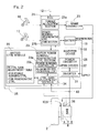
- Fig. 2 is a block diagram of a schematic configuration of an inverter device and the like of the electric vehicle.
- the electric vehicle includes an ECU 21 which is an electric control unit configured to perform general control of the vehicle, and an inverter device 22 configured to perform control of the traction motors 6 according to commands from the ECU 21.
- the ECU 21 includes a computer, programs which are executed by the computer, and various electronic circuits.
- the ECU 21 includes a torque allocation section 21 a and a power running/regenerative control command section 21b.
- the torque allocation section 21 a is configured to generate an accelerating/decelerating command as a torque command value, which is to be sent to the traction motors 6, 6 of the right and left wheels, on the basis of an accelerating command outputted from accelerator manipulation portion 16 such as an accelerator pedal, a decelerating command outputted from brake manipulation portion 17 such as a brake pedal, and a cornering or steering command from the steering portion 12, and to output the accelerating/decelerating command to each inverter device 22.
- the torque allocation section 21 a has a function to, in response to a decelerating command outputted from the brake manipulation portion 17, generate a braking torque command value allocated to regenerative braking of the motor 6 and a braking torque command value allocated to the operation of the electromechanical brakes 9 and 10.
- the braking torque command value allocated to regenerative braking reflects the accelerating/decelerating command which is to be sent to the motors 6 of the right and left wheels to a torque command value.
- the braking torque command value allocated to the operation of the brakes 9 and 10 is outputted to a brake controller 23.
- the power running/regenerative control command section 21b is configured to send a command flag for switching between acceleration (power running) and deceleration (regeneration), to a motor power running/regenerative control section 33 of a motor control module 29 described later.
- the inverter device 22 includes a power circuitry 28 provided for each motor 6, and the motor control module 29 configured to control the power circuitry 28.
- the power circuitry 28 includes an inverter 31 configured to convert a DC power from a battery 19 into a three-phase AC power used for power running and regeneration of the motor 6, and a PWM driver 32 configured to control the inverter 31.
- the motor 6 is, for example, a three-phase synchronous motor.
- the motor 6 is provided with a rotation angle sensor 36 configured to detect a rotation angle as an electrical angle of a rotor of the motor.
- the inverter 31 includes a plurality of semiconductor switching elements, and the PWM driver 32 performs pulse width modulation of an inputted current command and sends ON/OFF commands to each of the semiconductor switching elements.
- the motor control module 29 includes a computer, programs which are executed by the computer, and various electronic circuits.
- the motor control module 29 includes the motor power running/regenerative control section 33 as a basic control section, a control gain adjustment section 34, and a PI control gain adjustment table 35.
- the motor power running/regenerative control section 33 is configured to perform conversion of an accelerating (power running)/decelerating (regeneration) command such as a torque command sent from the ECU 21 as a primary control unit to a current command, and to send the current command to the PWM driver 32 of the power circuitry 28. Switching between power running and regeneration, that is, switching of the direction of a command current, is performed on the basis of the command flag from the power running/regenerative control command section 21b of the ECU 21.
- the motor power running/regenerative control section 33 includes power running controller 33a and regenerative controller 33b, and either the power running controller 33a or the regenerative controller 33b is selectively used on the basis of the command flag from the power running/regenerative control command section 21b.
- the motor power running/regenerative control section 33 generates an appropriate command current value in accordance with the direction of the command current instructed with the command flag, by using a torque table (not shown) which is preset in the inverter. At that time, a current PI control section 41 ( Fig. 4 ) described later performs PI feedback control so as to eliminate a deviation relative to the command current value generated in the inverter, in response to the torque command from the ECU 21. In addition, the motor power running/regenerative control section 33 obtains the rotation angle of the rotor of the motor 6 from the rotation angle sensor 36 via the control gain adjustment section 34 described next, and performs control corresponding to the rotation angle, such as vector control.
- the control gain adjustment section 34 adjusts a PI control gain of the current PI control section 41 ( Fig. 4 ) according to the PI control gain adjustment table 35 described later, such that a PI control gain corresponding to a running state is used.
- torque generation directions are different from each other between during power running and during regeneration. That is, during power running, as seen from the direction of an output shaft of each motor 6, torque in the CW direction is generated in the motor 6 at the left side, and torque in the CCW direction is generated in the motor 6 at the right side.
- the left side and the right side regarding the motors 6 are determined by the direction in which the vehicle is seen from the rear side (the same applies below).
- the torque generated in each of the motors at the right and left sides is transmitted via the cycloidal reducer 7 and the wheel bearing 4 to the tire while the direction of the torque at one side (the right side or the left side) is reversed.
- the direction of torque generated during regeneration is different from the direction of torque generated during power running.
- the PI control gain is automatically adjusted, which improves the responsiveness of each motor 6 and leads to improvement in occupant's riding comfort.
- Signal communication among the ECU 21, the inverter device 22, the brake controller 23, and the steering portion 12 is performed, for example, with controller area network (CAN) communication.
- CAN controller area network
- Fig. 3 is a block diagram of a torque control system, wherein the control gain adjustment section 34 of the motor control module 29 in the inverter device 22 is shown.
- Fig. 4 is a detailed block diagram of a current control unit 46 shown in Fig. 3 . A description will be given with reference to Figs. 3 and 4 .
- the motor control module 29 in Fig. 3 is configured to control a motor drive current and includes a current command section 40 shown in Fig. 4 .
- the motor control module 29 includes the current PI control section 41.
- the current command section 40 generates an appropriate command current by using the torque table (not shown), which is preset in the inverter 31 of the inverter device 22, on the basis of a detection value of a drive current which is applied to the motor 6 and is detected by the rotation angle sensor 36 and a torque command value which is an accelerating/decelerating command which is generated by the torque allocation section 21 a of the ECU 21 shown in Fig. 3 and has a sign representing the direction of acceleration/deceleration, that is, the direction of the command current.
- the torque table not shown
- an appropriate torque command value is calculated from a maximum torque control table on the basis of an accelerating signal and the rotation speed of the motor 6.
- the current command section 40 generates command values of a primary current (Ia) and a current phase angle ( ⁇ ) (not shown) of the motor 6 on the basis of the calculated torque command value.
- the current command section 40 generates two command currents, a d-axis current (magnetic field component) O_Id and a q-axis current (torque component) O_Iq, on the basis of the values of the primary current (Ia) and the current phase angle ( ⁇ ).
- the current PI control section 41 calculates control variables Vdc and Vqc as voltage values by PI control on the basis of the values of the d-axis current O_Id and the q-axis current O_Iq outputted from the current command section 40 and two-phase currents Id and Iq calculated by a three phase/two phase conversion section 42 using the motor current and the rotor angle, under proportional gain adjustment and integral gain adjustment at the control gain adjustment section 34.
- the rotor angle of the motor 6 which is used for the conversion is obtained from the rotation angle sensor 36.
- the PI control gain adjustment table 35 ( Fig. 2 ) includes two types of PI control gain adjustment tables 35 for power running control and for regenerative control.
- a PI control gain which is used when the current PI control section 41 performs PI feedback control is set in accordance with a running state.
- the output of the control gain adjustment section 34 is inputted to a current control block 37 corresponding to the power circuitry 28 shown in Fig. 2 .
- P manipulation amount : P Kp ⁇ E_CURR Kp is a proportional gain .
- I manipulation amount : I I + Ki ⁇ E_CURR Ki is an integral gain .
- the above current is an effective value of the motor phase current.
- the PI control gain adjustment table 35 is created according to the automatic adjustment rules.
- the PI control gain adjustment table 35 is recorded, for example, in a ROM which is a storage or memory provided in the inverter device 22.
- the motor control module 29 takes the value of the PI control gain from the PI control gain adjustment table 35 and controls the motor 6.
- the PI control gain adjustment tables 35 for power running control and for regenerative control are provided for each interval (e.g., 5 km/h) determined by regarding a vehicle speed.
- the control variables Vdc and Vqc which are calculated by the current PI control section 41 are inputted to a two phase/three phase conversion section 44.
- the two phase/three phase conversion section 44 convers the inputted two-phase control variables Vdc and Vqc to three-phase PWM duties Vu, Vv, and Vw using a rotor angle ⁇ of the motor 6 obtained by the rotation angle sensor 36.
- a power conversion section 45 corresponds to the power circuitry 28 in Fig. 2 , and PWM control of the inverter 31 ( Fig. 2 ) is performed in accordance with the PWM duties Vu, Vv, and Vw, and three-phase drive currents which drive the motor 6 are outputted.
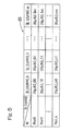
- Fig. 5 is a diagram showing the PI control gain adjustment table 35 in the control device for the electric vehicle.
- a horizontal row indicates the absolute value
- a vertical column indicates a vehicle speed N.
- Two types of PI control gain adjustment tables 35 are provided individually for power running control and for regenerative control.
- PI control gain adjustment tables 35 are provided individually for power running control and for regenerative control as described above, for example, disturbance caused due to a distinction in performance or a deterioration state of the battery 19, a distinction in loss of the motor 6 and the inverter device 22, or the like, is less influential, and it is possible to accurately control the motor 6 regardless of power running control or regenerative control. Thus, it is possible to finely control the motor 6. Therefore, it is possible to improve the responsiveness of the motor 6.
- Fig. 6 is an N-T (rotation speed-torque) chart of the motor in the electric vehicle.
- Fig. 6 shows the first quadrant and the fourth quadrant of the N-T chart of the motor.
- the first quadrant is an area in which power running control is performed, and positive torque occurs therein.
- the fourth quadrant is an area in which regenerative control is performed, and negative torque occurs therein.
- Fig. 7 is a diagram showing an example before and after improvement in overshoot during power running control.
- Fig. 7(a) is related to the conventional art, in which overshoot that the torque exceeds a command torque occurs during power running control.
- Fig. 7(b) improvement in overshoot mentioned above is achieved by using the control device according to the present embodiment.
- Fig. 8 is a diagram showing an example before and after improvement in overshoot during regenerative control.
- Fig. 8(a) is related to the conventional art, in which overshoot that the torque exceeds a command torque occurs during regenerative control.
- Fig. 8(b) improvement in overshoot mentioned above is achieved by using the control device according to the present embodiment.
- the motor control module 29 controls the power circuitry 28 on the basis of the accelerating/decelerating command, which is the torque command or the like sent from the ECU 21, during motor power running and regenerative control, and executes output of the motor 6 through torque control. That is, the current PI control section 41 in the motor control module 29 performs PI feedback control so as to eliminate a deviation relative to the command current value generated in the inverter, in response to the torque command from the ECU 21.
- the PI control gain adjustment tables 35 which are used during the PI feedback control are provided for power running control and for regenerative control, respectively, disturbance caused due to a distinction in performance or a deterioration state of the battery 19, a distinction in loss of the motor 6 and the inverter device 22, or the like, is less influential, and it is possible to more accurately control the motor 6 regardless of power running control or regenerative control. Therefore, it is possible to improve the responsiveness of the motor 6.
- the control gain adjustment section 34 adjusts the PI control gain of the current PI control section 41 according to the PI control gain adjustment table 35 such that the PI control gain corresponding to the running state is used. Since the PI control gain is optimally adjusted in accordance with the running state which changes every moment, an overshoot phenomenon can be avoided to, for example, suppress vibration of the reducer and the like. Thus, it is possible to improve the occupant's riding comfort.
- the PI control gain adjustment table 35 As the absolute value of the deviation (the deviation current value E_CURR) between the measured current value A_CURRand the command current value O_CURR of the motor 6 decreases, the integral gain in the PI control gain is decreased, and the proportional gain is decreased at the same time. In addition, as the absolute value of the deviation mentioned above increases, the integral gain is increased, and the proportional gain is increased at the same time.
- the PI control gain adjustment table 35 is set as described above on the basis of results of an actual vehicle test, or the like. Since the integral gain and the proportional gain are decreased as the absolute value of the deviation mentioned above decreases, it is possible to suppress overshoot in current control.
- a limit may be provided for a gain manipulation amount for manipulating the proportional gain or the integral gain. If the gain manipulation amount exceeds the limit, the control gain adjustment section 34 may use the limit as an upper limit. In this case, for example, it is possible to prevent an excessively large current from flowing to the PWM driver 32 of the power circuitry 28, thereby preventing abnormality occurrence of the inverter device 22.
- a limit may be provided for a command current value which corresponds to the value of current flowing to the motor 6 during power running control or the value of current flowing to the motor 6 during regenerative control. In this case, for example, it is possible to reduce influence of disturbance or temperature rise of the motor 6. Therefore, it is possible to prevent abnormality occurrence of the motor 6 which is caused due to temperature rise of the motor 6 or the like.
- the present invention is also applicable to an electric vehicle whose wheels are driven by motors disposed outside the wheels, such as an on-board type, in addition to an in-wheel motor type. Furthermore, the present invention is applicable to an electric vehicle whose four wheels are driven by respective motors, or an electric vehicle whose wheels are driven by a single motor.
Landscapes
- Engineering & Computer Science (AREA)
- Power Engineering (AREA)
- Transportation (AREA)
- Mechanical Engineering (AREA)
- Physics & Mathematics (AREA)
- General Physics & Mathematics (AREA)
- Automation & Control Theory (AREA)
- Electric Propulsion And Braking For Vehicles (AREA)
- Control Of Ac Motors In General (AREA)
Applications Claiming Priority (2)
| Application Number | Priority Date | Filing Date | Title |
|---|---|---|---|
| JP2013105987A JP6246496B2 (ja) | 2013-05-20 | 2013-05-20 | 電気自動車の制御装置 |
| PCT/JP2014/063000 WO2014188962A1 (fr) | 2013-05-20 | 2014-05-15 | Dispositif pour commander une automobile electrique |
Publications (2)
| Publication Number | Publication Date |
|---|---|
| EP3000648A1 true EP3000648A1 (fr) | 2016-03-30 |
| EP3000648A4 EP3000648A4 (fr) | 2017-01-25 |
Family
ID=51933519
Family Applications (1)
| Application Number | Title | Priority Date | Filing Date |
|---|---|---|---|
| EP14800264.5A Withdrawn EP3000648A4 (fr) | 2013-05-20 | 2014-05-15 | Dispositif pour commander une automobile electrique |
Country Status (5)
| Country | Link |
|---|---|
| US (1) | US10017075B2 (fr) |
| EP (1) | EP3000648A4 (fr) |
| JP (1) | JP6246496B2 (fr) |
| CN (1) | CN105228855B (fr) |
| WO (1) | WO2014188962A1 (fr) |
Cited By (1)
| Publication number | Priority date | Publication date | Assignee | Title |
|---|---|---|---|---|
| AT522508A1 (de) * | 2019-05-13 | 2020-11-15 | Avl List Gmbh | Verfahren zur Regelung des Antriebs eines elektrischen Fahrzeugs |
Families Citing this family (8)
| Publication number | Priority date | Publication date | Assignee | Title |
|---|---|---|---|---|
| US11303240B2 (en) * | 2018-07-03 | 2022-04-12 | Kubota Corporation | Traveling control device |
| JP7132079B2 (ja) * | 2018-10-15 | 2022-09-06 | 日立Astemo株式会社 | モータ駆動装置、電動車両システム |
| KR102676240B1 (ko) * | 2019-03-27 | 2024-06-20 | 현대자동차주식회사 | 하이브리드 자동차 및 그를 위한 제동 제어 방법 |
| JP7271266B2 (ja) * | 2019-03-29 | 2023-05-11 | ニデック株式会社 | 制御装置 |
| JP7376290B2 (ja) * | 2019-09-10 | 2023-11-08 | 株式会社ジェイテクト | 操舵制御装置 |
| CN110834544B (zh) * | 2019-11-19 | 2021-04-20 | 北京理工大学 | 一种基于模糊-pi复合控制的纯电动汽车恒流控制系统和方法 |
| CN114291766B (zh) * | 2021-12-20 | 2024-04-12 | 河南嘉晨智能控制股份有限公司 | 一种工业车辆微动驾驶感改善方法 |
| JP2025067588A (ja) * | 2023-10-13 | 2025-04-24 | トヨタ自動車株式会社 | 電動車両の制御装置 |
Family Cites Families (15)
| Publication number | Priority date | Publication date | Assignee | Title |
|---|---|---|---|---|
| JPS63316687A (ja) * | 1987-06-18 | 1988-12-23 | Mitsubishi Electric Corp | 誘導電動機のベクトル制御演算装置 |
| JP3235428B2 (ja) * | 1995-09-28 | 2001-12-04 | 日産自動車株式会社 | モータ制御装置 |
| JP3293435B2 (ja) * | 1995-11-20 | 2002-06-17 | セイコーエプソン株式会社 | モータ駆動装置 |
| JP3262709B2 (ja) * | 1996-04-25 | 2002-03-04 | 三菱電機株式会社 | モータのベクトル制御方法およびベクトル制御インバータ装置 |
| JP3566151B2 (ja) | 1999-10-04 | 2004-09-15 | 本田技研工業株式会社 | ハイブリッド自動車のモータ制御装置 |
| JP2004116467A (ja) | 2002-09-27 | 2004-04-15 | Denso Corp | フィードバック制御システム |
| JP4143912B2 (ja) * | 2002-12-02 | 2008-09-03 | 東芝キヤリア株式会社 | 電動機の制御装置 |
| JP4496895B2 (ja) * | 2004-09-01 | 2010-07-07 | パナソニック株式会社 | 電動機の制御装置 |
| JP4797476B2 (ja) | 2005-07-12 | 2011-10-19 | トヨタ自動車株式会社 | 二次電池の制御装置 |
| CN101007510B (zh) * | 2006-12-08 | 2010-05-26 | 奇瑞汽车股份有限公司 | 一种混合动力汽车用电机的控制方法 |
| JP2009112163A (ja) * | 2007-10-31 | 2009-05-21 | Aisin Aw Co Ltd | 電動機制御装置,駆動装置およびハイブリッド駆動装置 |
| JP5035641B2 (ja) * | 2009-11-30 | 2012-09-26 | アイシン・エィ・ダブリュ株式会社 | 電動機駆動装置の制御装置 |
| US8294413B2 (en) * | 2010-01-05 | 2012-10-23 | GM Global Technology Operations LLC | Induction motor control systems and methods |
| JP5705585B2 (ja) | 2011-02-25 | 2015-04-22 | Ntn株式会社 | 電気自動車 |
| WO2013077888A1 (fr) * | 2011-11-22 | 2013-05-30 | Quantum Fuel Systems Technologies Worldwide, Inc. | Ensemble chargeur et dispositif de force motrice |
-
2013
- 2013-05-20 JP JP2013105987A patent/JP6246496B2/ja not_active Expired - Fee Related
-
2014
- 2014-05-15 EP EP14800264.5A patent/EP3000648A4/fr not_active Withdrawn
- 2014-05-15 CN CN201480028841.1A patent/CN105228855B/zh not_active Expired - Fee Related
- 2014-05-15 WO PCT/JP2014/063000 patent/WO2014188962A1/fr not_active Ceased
-
2015
- 2015-11-17 US US14/943,743 patent/US10017075B2/en not_active Expired - Fee Related
Non-Patent Citations (1)
| Title |
|---|
| See references of WO2014188962A1 * |
Cited By (2)
| Publication number | Priority date | Publication date | Assignee | Title |
|---|---|---|---|---|
| AT522508A1 (de) * | 2019-05-13 | 2020-11-15 | Avl List Gmbh | Verfahren zur Regelung des Antriebs eines elektrischen Fahrzeugs |
| AT522508B1 (de) * | 2019-05-13 | 2022-02-15 | Avl List Gmbh | Verfahren zur Regelung des Antriebs eines elektrischen Fahrzeugs |
Also Published As
| Publication number | Publication date |
|---|---|
| JP6246496B2 (ja) | 2017-12-13 |
| WO2014188962A1 (fr) | 2014-11-27 |
| CN105228855B (zh) | 2018-03-20 |
| JP2014230322A (ja) | 2014-12-08 |
| CN105228855A (zh) | 2016-01-06 |
| US10017075B2 (en) | 2018-07-10 |
| US20160068081A1 (en) | 2016-03-10 |
| EP3000648A4 (fr) | 2017-01-25 |
Similar Documents
| Publication | Publication Date | Title |
|---|---|---|
| US10017075B2 (en) | Device for controlling electric automobile | |
| US9855858B2 (en) | Control device for electric vehicle | |
| US10093308B2 (en) | Electronic stability control system for vehicle | |
| US9919617B2 (en) | Control device for electric motor vehicle and control method for electric motor vehicle | |
| EP3072730A1 (fr) | Dispositif de commande de frein antiblocage | |
| US10889188B2 (en) | Drive control device for vehicle with independently driven wheels | |
| JP6584779B2 (ja) | 車両姿勢制御装置 | |
| EP3466785A1 (fr) | Dispositif de commande de virage de véhicule | |
| US9586484B2 (en) | Electric-vehicle control device | |
| JP2017005899A (ja) | 車輪独立駆動式車両の駆動制御装置 | |
| US9956890B2 (en) | Device for controlling electric automobile | |
| WO2016043077A1 (fr) | Dispositif de commande d'entraînement de véhicule | |
| WO2017018335A1 (fr) | Dispositif d'entraînement par moteur | |
| JP2016086522A (ja) | 車両の駆動力制御装置 | |
| JP5908290B2 (ja) | 電動車両の制御装置 | |
| US12483169B2 (en) | Synchronous motor driving device and synchronous motor driving method | |
| JP2016208686A (ja) | 電動車両 | |
| JP2016220271A (ja) | 電気自動車の制御装置 | |
| JP6547410B2 (ja) | 車両の駆動力制御装置 |
Legal Events
| Date | Code | Title | Description |
|---|---|---|---|
| PUAI | Public reference made under article 153(3) epc to a published international application that has entered the european phase |
Free format text: ORIGINAL CODE: 0009012 |
|
| 17P | Request for examination filed |
Effective date: 20151118 |
|
| AK | Designated contracting states |
Kind code of ref document: A1 Designated state(s): AL AT BE BG CH CY CZ DE DK EE ES FI FR GB GR HR HU IE IS IT LI LT LU LV MC MK MT NL NO PL PT RO RS SE SI SK SM TR |
|
| AX | Request for extension of the european patent |
Extension state: BA ME |
|
| DAX | Request for extension of the european patent (deleted) | ||
| A4 | Supplementary search report drawn up and despatched |
Effective date: 20170103 |
|
| RIC1 | Information provided on ipc code assigned before grant |
Ipc: B60L 15/02 20060101ALI20161221BHEP Ipc: B60L 7/10 20060101ALI20161221BHEP Ipc: B60L 15/20 20060101AFI20161221BHEP Ipc: H02P 27/06 20060101ALI20161221BHEP Ipc: H02P 23/00 20160101ALI20161221BHEP Ipc: G05B 11/42 20060101ALI20161221BHEP |
|
| 17Q | First examination report despatched |
Effective date: 20171206 |
|
| STAA | Information on the status of an ep patent application or granted ep patent |
Free format text: STATUS: THE APPLICATION IS DEEMED TO BE WITHDRAWN |
|
| 18D | Application deemed to be withdrawn |
Effective date: 20191203 |