EP3000666A1 - Vorrichtung zum betreiben einer fahrzeugparkbremse - Google Patents
Vorrichtung zum betreiben einer fahrzeugparkbremse Download PDFInfo
- Publication number
- EP3000666A1 EP3000666A1 EP13885440.1A EP13885440A EP3000666A1 EP 3000666 A1 EP3000666 A1 EP 3000666A1 EP 13885440 A EP13885440 A EP 13885440A EP 3000666 A1 EP3000666 A1 EP 3000666A1
- Authority
- EP
- European Patent Office
- Prior art keywords
- operation pedal
- return spring
- pedal
- end portion
- parking brake
- Prior art date
- Legal status (The legal status is an assumption and is not a legal conclusion. Google has not performed a legal analysis and makes no representation as to the accuracy of the status listed.)
- Granted
Links
- 238000004804 winding Methods 0.000 claims description 33
- 230000000994 depressogenic effect Effects 0.000 description 4
- 238000005452 bending Methods 0.000 description 2
- 238000006073 displacement reaction Methods 0.000 description 2
- 238000000034 method Methods 0.000 description 2
- 230000001629 suppression Effects 0.000 description 2
- 229910000831 Steel Inorganic materials 0.000 description 1
- 230000000881 depressing effect Effects 0.000 description 1
- 238000010586 diagram Methods 0.000 description 1
- 230000000694 effects Effects 0.000 description 1
- 239000000463 material Substances 0.000 description 1
- 239000007769 metal material Substances 0.000 description 1
- 239000010959 steel Substances 0.000 description 1
Images




Classifications
-
- B—PERFORMING OPERATIONS; TRANSPORTING
- B60—VEHICLES IN GENERAL
- B60T—VEHICLE BRAKE CONTROL SYSTEMS OR PARTS THEREOF; BRAKE CONTROL SYSTEMS OR PARTS THEREOF, IN GENERAL; ARRANGEMENT OF BRAKING ELEMENTS ON VEHICLES IN GENERAL; PORTABLE DEVICES FOR PREVENTING UNWANTED MOVEMENT OF VEHICLES; VEHICLE MODIFICATIONS TO FACILITATE COOLING OF BRAKES
- B60T7/00—Brake-action initiating means
- B60T7/02—Brake-action initiating means for personal initiation
- B60T7/04—Brake-action initiating means for personal initiation foot actuated
- B60T7/06—Disposition of pedal
-
- G—PHYSICS
- G05—CONTROLLING; REGULATING
- G05G—CONTROL DEVICES OR SYSTEMS INSOFAR AS CHARACTERISED BY MECHANICAL FEATURES ONLY
- G05G1/00—Controlling members, e.g. knobs or handles; Assemblies or arrangements thereof; Indicating position of controlling members
- G05G1/30—Controlling members actuated by foot
- G05G1/44—Controlling members actuated by foot pivoting
Definitions
- the present invention relates to operation devices for vehicle parking brakes, and more particularly to a technique of suppressing backlash in the lateral direction of an operation pedal without increasing the number of parts, assembly time, and the weight of the device.
- One type of operation device for a vehicle parking brake includes: a support bracket fixed to a vehicle body and having a pair of first and second side plates, the first and second side plates facing each other with a predetermined interval therebetween; an operation pedal supported between the first and second side plates of the support bracket so as to be pivotable about a pivot axis; and a return spring that has one end portion hooked on the operation pedal and the other end portion hooked on the first side plate and a portion located between the end portions and wound about the pivot axis and that biases the operation pedal toward its original position.
- the operation pedal is operated to pivot about the pivot axis, so that a parking brake cable is subjected to a tensile force, thereby operating the parking brake.
- any backlash in the lateral direction of the operation pedal that is depressed with a foot may give an operator an uncomfortable feeling. It is therefore desired to minimize the backlash in the lateral direction of the operation pedal so as not to impair the operation feeling the operator has when operating the parking brake of the vehicle.
- Patent Documents 1, 2 and 3 do not have a mechanism that suppresses backlash in the lateral direction of the operation pedal, and these operation devices therefore do not satisfy the required values of the operation performance of the operation pedal.
- One solution to this is to provide a mechanism that suppresses backlash in the lateral direction of the operation pedal.
- the operation device needs to be a relatively large device requiring a large number of parts. This is disadvantageous as it increases assembly time, vehicle weight, and cost and reduces space on the front floor.
- the present invention was developed in view of the above circumstances, and it is an object of the present invention to provide an operation device for a vehicle parking brake which has a simple configuration with no backlash in the lateral direction of an operation pedal.
- the return spring is wound into a coil shape about the pivot axis of the operation pedal, and has one end portion hooked on the operation pedal and the other end portion hooked on the first side plate, thereby biasing the operation pedal toward its original position. Accordingly, the return spring is disposed in a tilted manner so that the entire return spring is twisted, and a part of the operation pedal on which the one end portion of the return spring is hooked is subjected to a force toward the first side plate, whereby a stepping surface of the operation pedal, namely a surface to be stepped on, is subjected to moment in such a direction that the stepping surface of the operation pedal is moved to face toward the first side plate.
- bending and forming the one end portion on the operation pedal side of the return spring so as to bias the operation pedal toward the return spring suitably eliminates backlash in the pivot axis direction, namely the lateral (right-left) direction, of the operation pedal.
- the present invention is based on the above knowledge.
- the principle of the present invention provides an operation device for a vehicle parking brake, which includes: (a) a support bracket fixed to a vehicle body and having a pair of first and second side plates, the first and second side plates facing each other with a predetermined interval therebetween; an operation pedal supported between the first and second side plates of the support bracket so as to be pivotable about a pivot axis; and a return spring that has one end portion hooked on the operation pedal and the other end portion hooked on the first side plate and a winding portion located between the end portions and wound about the pivot axis and that biases the operation pedal toward its original position, and in which the operation pedal is operated to pivot about the pivot axis, so that a parking brake cable is subjected to a tensile force, thereby operating the parking brake, characterized in that (b) one of the end portions of the return spring is bent and formed so as to bias a pedal pad of the operation pedal toward the first side plate or the second side plate.
- the return spring is wound about the pivot axis into a coil shape, and the one end portion of the return spring adjacent to the operation pedal is bent and formed so as to bias the pedal pad of the operation pedal toward the first side plate or the second side plate when attached.
- the return spring wound into a coil shape is therefore disposed in a tilted manner so that the entire return spring is twisted, and the pedal pad of the operation pedal is subjected to the moment in such a direction that the stepping surface of the pedal pad faces toward the first side plate or the second side plate.
- the one end portion of the return spring adjacent to the operation pedal projects from the winding portion in a direction tangential thereto and is bent at a predetermined angle toward the first side plate.
- the return spring wound into a coil shape is therefore disposed in a tilted manner so that the entire return spring is twisted, and the operation pedal is subjected to the moment in such a direction that the stepping surface of the pedal pad faces toward the first side plate. Accordingly, backlash in the lateral direction of the operation pedal is suitably suppressed.
- a base end portion of the operation pedal has such a thickness dimension in a direction of the pivot axis that the base end portion of the operation pedal overlaps the winding portion in a radial direction of the winding portion, and has a hook hole through which the one end portion of the return spring adjacent to the operation pedal is hooked, the hook hole being located closer to the second side plate than a center plane located in a middle in a thickness direction of the base end portion is, and (e) the one end portion of the return spring adjacent to the operation pedal is formed so as to be bent toward the center plane side of the operation pedal.
- the return spring wound into a coil shape is therefore disposed in a tilted manner so that the entire return spring is twisted, and the operation pedal is subjected to the moment in such a direction that the stepping surface of the pedal pad faces toward the first side plate. Accordingly, backlash in the lateral direction of the operation pedal is suitably suppressed.
- the hook hole which is formed in the base end portion of the operation pedal and through which the one end portion of the return spring adjacent to the operation pedal is hooked, is located between the pivot axis and the pedal pad of the operation pedal in a longitudinal direction of a vehicle.
- the return spring wound into a coil shape is thus disposed in a tilted manner so that the entire return spring is twisted, and the operation pedal is subjected to the moment in such a direction that the stepping surface of the pedal pad faces toward the first side plate. Accordingly, backlash in the lateral direction of the operation pedal is suitably suppressed.
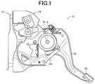
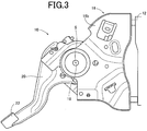
- FIGS. 1 , 2 , and 3 are a left side view, a front view, and a right side view of a foot operated parking brake operation device 10 according to an embodiment of the present invention.
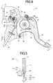
- FIG. 4 shows the foot operated parking brake operation device 10, as viewed from the side (left side) of a vehicle, with a left bracket 14 removed in order to illustrate the configuration of the foot operated parking brake operation device 10.
- the foot operated parking brake operation device 10 includes an operation pedal 20 that is disposed with right and left brackets 16, 14 fixedly attached to a vehicle body 12 at positions forward of the driver's seat of a vehicle so that the operation pedal 20 can pivot about a pivot axis S by a support shaft 18.
- the left bracket 14 and the right bracket 16 include base plate portions 14a, 16a fixed to the vehicle body 12, and side plate portions 14b, 16b bent at right angles from the base plate portions 14a, 16a and facing each other.
- the base end portion of the operation pedal 20 is supported by a pair of the side plate portions 14b, 16b so that the operation pedal 20 can pivot about the support shaft 18.
- a pedal pad 22 is provided at the distal end portion, namely the lower end portion, of the operation pedal 20.
- a ratchet 28 having multiple teeth 26 along an arc shape about the pivot axis S is attached to the upper front part of the operation pedal 20.
- an engaging tooth 34 of a pawl 32 that is rotatably disposed on the bracket via a pawl pin 30 parallel to the pivot axis S engages with the tooth 26 of the ratchet 28
- backward pivoting motion of the operation pedal 20 toward its original position is prevented and the operating state of the parking brake is maintained.
- the pawl 32 is biased to pivot clockwise about the pawl pin 30 as viewed in the figure by a torsion coil spring 36 hooked on the pawl 32 and the bracket.
- the engaging tooth 34 thus engages with the tooth 26 of the ratchet 28.
- the teeth 26 of the ratchet 28 are inclined teeth having a slope whose height is made larger along the opposite direction to a direction A in which the operation pedal 20 pivots about the pivot axis S when depressed.
- the pawl 32 biased by the torsion coil spring 34 can thus swing against the biasing force and ride over the teeth 26.
- the operation pedal 20 pivots backward according to the tensile force of the parking brake cable 24, and the triangular engaging tooth 34 enters a tooth space of the ratchet 28 and contacts a locking surface and a bottom land of the tooth 26, preventing any further backward pivoting motion of the operation pedal 20.
- the operating state of the parking brake is thus maintained.
- Both the ratchet 28 and the pawl 32 are made of a metal material.
- the locking surface and a side end face of the engaging tooth 34 which faces the locking surface are linear flat surfaces and substantially closely contact each other, and the bottom land and a tip end face of the engaging tooth 36 are cylindrical surfaces having an arc shape with substantially the same curvature as viewed from the side and substantially closely contact each other.
- the locked state, or the operating state of the parking brake, is thus stably maintained.
- the pawl pin 30 is inserted through a long hole 42 formed in the pawl 32.
- the center of rotation of the pawl 32 changes due to the tensile force of the parking brake cable 24, and the biasing direction of the torsion coil spring 36 is reversed. Accordingly, when the operation pedal 20 is depressed again and the pawl 32 is disengaged from the ratchet 28, the pawl 32 pivots counterclockwise about the pawl pin 30 as viewed in the figure according to the biasing force of the torsion coil spring 36, so that the pawl 32 is not allowed to engage with the ratchet 28.
- the operation pedal 20 is biased to pivot about the pivot axis S toward its original position by a return spring 44 that has two end portions, namely a pair of end portions 44a, 44b, one of which is hooked on the base end portion of the operation pedal 20 and the other of which is hooked on the side plate portion 14b of the left bracket 14 and has its portion between the end portions 44a, 44b, namely a winding portion 44c, wound about the support shaft 18 or the pivot axis S.
- the operation pedal 20 pivots backward to the original position shown in FIGS. 1 to 4 according to the biasing force of the return spring 44 and the tensile force of the parking brake cable 24.
- the original position of the operation pedal 20 is determined by a stopper 46 attached to the side plate portion of the bracket.
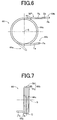
- FIGS. 5 , 6, and 7 are a plan view, a left side view, and a front view showing the shape of the return spring 44 after the return spring 44 is attached.
- the end portion 44a is located at a position shown by a dashed line in FIG. 6 .
- the return spring 44 includes the end portions 44a, 44b, one of which is hooked on the base end portion of the operation pedal 20 and the other of which is hooked on the side plate portion 14b of the left bracket 14, and the winding portion 44c between the end portions 44a, 44b which is wound about the pivot axis S or the support shaft 18.
- the winding portion 44c has the same axis as the pivot axis.
- the operation pedal 20 is a pressed part produced by bending a single steel sheet into a longitudinal shape having a U-shape in section perpendicular to its longitudinal direction.
- the operation pedal 20 is positioned in the pivot axis S direction so that a center plane C of the thickness dimension in the pivot axis S direction of the operation pedal 20, which is a plane perpendicular to the pivot axis S of the base end portion of the operation pedal 20, passes through the winding portion 44c of the return spring 44.
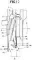
- FIGS. 8 , 9 , and 10 are a perspective view with the left bracket 14 removed, a perspective view with the right bracket 16 removed, and an enlarged front view, illustrating how the return spring 44 is attached.
- the end portion 44a of the return spring 44 which is hooked on the side plate portion 14b of the left bracket 14 includes a linear portion Ta extending from the winding portion 44c in a direction tangential to the winding portion 44c, and a hook portion Fa bent at right angles to the linear portion Ta so as to be parallel to the pivot axis S.
- the hook portion Fa is hooked through a hook hole 14c as a through hole extending through the side plate portion 14b of the left bracket 14.
- the end portion 44b of the return spring 44 which is hooked on the base end portion of the operation pedal 20 includes a linear portion Kb extending in a direction tangential to the winding portion 44c, a linear bent portion Tb having a length Lb and bent at a bend point MP at a predetermined bend angle ⁇ with respect to the center plane C of the operation pedal 20 from the winding portion 44c toward the left bracket 14, namely toward the center plane C of the operation pedal 20, an offset portion Sb bent at right angles to the bent portion Tb, and a hook portion Fb bent at right angles to the offset portion Sb.
- the hook portion Fb is hooked through a hook hole 20a as a through hole extending through the right bracket 16 side of the base end portion of the operation pedal 20 in the pivot axis S direction.
- the bent portion Tb, the hook portion Fb, and the hook hole 20a through which the hook portion Fb is hooked are located between the axis S of the support shaft 18 and the pedal pad 22 in the longitudinal direction of the vehicle which is the lateral (horizontal) direction in FIG. 4 , so that the elastic restoring force of the bent portion Tb is applied in a direction toward the left bracket 14 to a region between the axis S and the pedal pad 22.
- the length Lb of the bent portion Tb is set to about 25 mm in view of the balance between suppression of lateral backlash and ease of assembly. Setting the length Lb to a value smaller than about 25 mm tends to affect the ease of assembly, and setting length Lb to a value larger than about 25 mm tends to affect the suppression of lateral backlash.
- the bent portion Tb of the end portion 44b of the return spring 44 is bent at the bend point MP at the predetermined bend angle ⁇ with respect to the center plane C of the operation pedal 20 from the winding portion 44c toward the left bracket 14, namely toward the center plane C of the operation pedal 20, so as to extend in a direction tangential to the winding portion 44c. Accordingly, when the hook portion Fb of the end portion 44b is deformed in such a direction that the hook portion Fb becomes parallel to the center plane C of the operation pedal 20, and is engaged with the hook hole 20a as a through hole extending through the base end portion of the operation pedal 20 as shown in FIG.
- clockwise moment M is generated about the intersection P of the pivot axis S and the center plane C in the front view of FIG. 10 by the elastic restoring force of the bent portion Tb as shown in FIG. 10 .
- a center plane C' of the winding portion 44c is tilted with respect to the center plane C, namely the center plane before attachment of the return spring 44, so that the entire return spring is twisted, and a stepping surface of the pedal pad 22 of the operation pedal 20, namely a surface to be stepped on, is tilted in such a direction that the stepping surface of the pedal pad faces toward the left bracket 14, namely toward the left side of the vehicle.
- the winding portion 44c of the return spring 44 and the side plate portion 16b of the right bracket 16 contact each other in a pressurized state.
- a bend point contact region Rb in FIG. 8 the bend point MP of the end portion 44b of the return spring 44 adjacent to the right bracket 16 and the side plate portion 16b of the right bracket 16 contact each other in a pressurized state.
- a winding portion contact region R14 in FIG. 9 the winding portion 44c of the return spring 44 and the side plate portion 14b of the left bracket 14 contact each other in a pressurized state.
- Such pressurization suitably eliminates backlash in the lateral direction, namely lateral backlash, of the pedal pad 22 of the operation pedal 20.
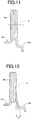
- test piece 1 of the return spring shown in FIG. 11 and test piece 2 and test piece 3 of the return spring shown in FIG. 12 by winding a piano wire (JIS G 3522) with a diameter of ⁇ 3.8 mm so that the winding portion 44c had a winding diameter (inside diameter of the coil) of ⁇ 66.2 mm.
- the test piece 1 is similar to the return spring 44 except that the test piece 1 is not bent at the bend point MP and the linear portion Kb and the bent portion Tb are present on a straight line.
- test piece 2 and the test piece 3 are similar to the return spring 44 except that the bent portion Tb is bent toward the right bracket 16, namely in the opposite direction to that in the above embodiment, and the bend angle ⁇ of the bent portion Tb with respect to the center plane C is 15° and 25°.
- These test pieces 1, 2, and 3 were used to measure backlash in the lateral direction (lateral backlash) of the pedal pad 22 under the following test conditions.
- test piece 1 had lateral backlash of 6.8 mm, and the test pieces 2, 3 had lateral backlash of 6.4 mm and 6.7 mm. These lateral backlash values are higher than a preset quality standard value of 3 mm. The test pieces 1 to 3 therefore fail to meet the requirements.
- test pieces 4 to 9 by using wires of the same material and the same diameter and using the same winding diameter as in the test pieces 1 to 3.
- These test pieces 4 to 9 have a configuration similar to that of the return spring 44 shown in FIGS. 5 to 7 etc. of the above embodiment, but their bend angles ⁇ at the bend point MP are 20°, 21°, 22°, 23°, 24°, and 25°.
- the inventors conducted a lateral backlash test similar to that described above by using the six kinds of test pieces 4 to 9.
- FIG. 13 shows the result of experiments carried out by the inventors.
- the return spring 44 is wound about the pivot axis S into a coil shape, and the end portion 44b of the return spring 44 adjacent to the operation pedal 20 is bent and formed so as to bias the operation pedal 20 toward the side plate portion 14b (first side plate) of the left bracket 14 when attached.
- the return spring 44 wound into a coil shape is therefore disposed in a tilted manner so that the entire return spring 44 is twisted as shown in FIG. 10 , and the operation pedal 20 is subjected to the moment M in such a direction that the stepping surface of the pedal pad 22 faces toward the side plate portion 14b of the left bracket 14.
- the end portion 44b of the return spring 44 adjacent to the operation pedal 20 projects in the direction tangential to the winding portion 44c and is bent at the predetermined bend angle ⁇ toward the side plate portion 14b (first side plate) of the left bracket 14.
- the return spring 44 wound into a coil shape is therefore disposed in a tilted manner so that the entire return spring 44 is twisted, and the operation pedal 20 is subjected to the moment M in such a direction that the stepping surface of the pedal pad 22 faces toward the side plate portion 14b of the left bracket 14. Accordingly, backlash in the lateral direction of the operation pedal 20 is suitably suppressed.
- the base end portion of the operation pedal 20 has such a thickness dimension in the pivot axis S direction that the base end portion of the operation pedal 20 overlaps the winding portion 44c in the radial direction of the winding portion 44c.
- the base end portion of the operation pedal 20 has the hook hole 20a through which the end portion 44b of the return spring 44 adjacent to the operation pedal 20 is hooked, the hook hole 20a is located closer to the side plate portion 16b (second side plate) of the right bracket 16 than the center plane C located in the middle in the thickness direction of the base end portion is, and the end portion 44b of the return spring 44 adjacent to the operation pedal 20 is formed so as to be bent toward the center plane C of the operation pedal 20.
- the return spring 44 wound into a coil shape is therefore disposed in a tilted manner so that the entire return spring 44 is twisted, and the operation pedal 20 is subjected to the moment M in such a direction that the stepping surface of the pedal pad 22 faces toward the side plate portion 14b of the left bracket 14. Accordingly, backlash in the lateral direction of the operation pedal 20 is suitably suppressed.
- the hook hole 20a which is formed in the base end portion of the operation pedal 20 and through which the end portion 44b of the return spring 44 adjacent to the operation pedal 20 is hooked, is located between the pivot axis S and the pedal pad 22 of the operation pedal 20 in the longitudinal direction of the vehicle which is the lateral (horizontal) direction in FIG. 4 .
- the return spring 44 wound into a coil shape is thus disposed in a tilted manner so that the entire return spring 44 is twisted, and the operation pedal 20 is subjected to the moment M in such a direction that the stepping surface of the pedal pad 22 faces toward the side plate portion 14b (first side plate) of the left bracket 14. Accordingly, backlash in the lateral direction of the operation pedal 20 is suitably suppressed.
- the pair of right and left brackets 16, 14 is used as separate parts in the above embodiment.
- the left bracket 14 and the right bracket 16 may be a single-piece member.
- any bracket including the left side plate portion 14a and the right side plate portion 16a can be used in the present invention.
- the return spring 44 of the above embodiment generates the moment M as the end portion 44b of the return spring 44 biases the region between the pivot axis S and the pedal pad 22 of the operation pedal 20 in the longitudinal direction of the vehicle toward the left bracket 14.
- the return spring 44 may have any other shape as long as it generates the moment M.
- the end portion 44a of the return spring 44 adjacent to the left bracket 14 may project in the opposite direction to that of the end portion 44b of the return spring 44 adjacent to the right bracket 16 with respect to the pivot axis S and may be bent and formed to have a bent portion similar to the bent portion Tb of the end portion 44b in the above embodiment so as to cause the winding portion 44c to generate a biasing force in the direction toward the left bracket 14.
- the return spring 44 is attached so as to be twisted in the opposite direction to that shown in FIG. 10 , and moment in the opposite direction to that of the moment M is generated, so that the pedal pad 22 of the operation pedal 20 is biased toward the right bracket 16. Accordingly, lateral backlash in the pedal pad 22 of the operation pedal 20 is suitably suppressed in this case as well.
Landscapes
- Engineering & Computer Science (AREA)
- Transportation (AREA)
- Mechanical Engineering (AREA)
- Physics & Mathematics (AREA)
- General Physics & Mathematics (AREA)
- Automation & Control Theory (AREA)
- Braking Elements And Transmission Devices (AREA)
- Mechanical Control Devices (AREA)
Applications Claiming Priority (1)
| Application Number | Priority Date | Filing Date | Title |
|---|---|---|---|
| PCT/JP2013/064127 WO2014188519A1 (ja) | 2013-05-21 | 2013-05-21 | 車両用パーキングブレーキの操作装置 |
Publications (3)
| Publication Number | Publication Date |
|---|---|
| EP3000666A1 true EP3000666A1 (de) | 2016-03-30 |
| EP3000666A4 EP3000666A4 (de) | 2016-12-28 |
| EP3000666B1 EP3000666B1 (de) | 2018-01-31 |
Family
ID=51933109
Family Applications (1)
| Application Number | Title | Priority Date | Filing Date |
|---|---|---|---|
| EP13885440.1A Not-in-force EP3000666B1 (de) | 2013-05-21 | 2013-05-21 | Vorrichtung zum betreiben einer fahrzeugparkbremse |
Country Status (6)
| Country | Link |
|---|---|
| US (1) | US9944258B2 (de) |
| EP (1) | EP3000666B1 (de) |
| JP (1) | JP5989241B2 (de) |
| KR (1) | KR101717007B1 (de) |
| CN (1) | CN105228869B (de) |
| WO (1) | WO2014188519A1 (de) |
Families Citing this family (1)
| Publication number | Priority date | Publication date | Assignee | Title |
|---|---|---|---|---|
| US10076975B2 (en) * | 2016-08-11 | 2018-09-18 | Goodrich Corporation | Brake release for aircraft seat |
Family Cites Families (28)
| Publication number | Priority date | Publication date | Assignee | Title |
|---|---|---|---|---|
| FR1212993A (fr) * | 1957-10-21 | 1960-03-28 | Bendix Aviat Corp | Commande irréversible utilisable en particulier comme commande de frein |
| US2975654A (en) * | 1958-07-11 | 1961-03-21 | Mount Clemens Metal Products C | Brake lever assembly |
| US3929033A (en) * | 1974-11-20 | 1975-12-30 | Atwood Vacuum Machine Co | Vehicle parking brake control |
| JPH034825A (ja) | 1989-05-31 | 1991-01-10 | Tokyo Electric Co Ltd | アップライト形電気掃除機 |
| JPH086657Y2 (ja) * | 1990-10-04 | 1996-02-28 | 日本発条株式会社 | 足踏み式パーキングブレーキ装置 |
| JPH04232155A (ja) * | 1990-12-28 | 1992-08-20 | Nhk Spring Co Ltd | 足踏み式駐車ブレーキ |
| US5385068A (en) * | 1992-12-18 | 1995-01-31 | Cts Corporation | Electronic accelerator pedal assembly with pedal force sensor |
| US5416295A (en) * | 1992-12-18 | 1995-05-16 | Cts Corporation | Combined pedal force switch and position sensor |
| JP3247493B2 (ja) * | 1993-06-16 | 2002-01-15 | 本田技研工業株式会社 | パーキングブレーキ装置 |
| JP3669009B2 (ja) | 1995-07-20 | 2005-07-06 | アイシン精機株式会社 | 車両用足踏式パーキングブレーキ制御装置 |
| KR19980054483U (ko) | 1996-12-31 | 1998-10-07 | 박병재 | 페달 리턴스프링 장착구조 |
| JP2967406B2 (ja) * | 1997-04-14 | 1999-10-25 | 株式会社エフテック | 足踏み式パーキングブレーキ装置 |
| JPH1134825A (ja) | 1997-07-24 | 1999-02-09 | Aisin Seiki Co Ltd | 車両用パーキングブレーキ装置 |
| JP3542709B2 (ja) * | 1998-01-13 | 2004-07-14 | 株式会社ヨロズ | 自動車のブレーキペダル装置 |
| JPH11245782A (ja) * | 1998-03-02 | 1999-09-14 | Toyota Iron Works Co Ltd | 足踏み式パーキングブレーキ操作装置 |
| US6240801B1 (en) | 1998-03-20 | 2001-06-05 | Oiles Corporation | Friction damper and pedal device for vehicle having the friction damper |
| JP4472043B2 (ja) * | 1998-03-23 | 2010-06-02 | オイレス工業株式会社 | ペダル装置 |
| JP3936729B2 (ja) * | 1998-05-12 | 2007-06-27 | 豊田鉄工株式会社 | 足踏み式パーキングブレーキ操作装置 |
| JP4021581B2 (ja) * | 1999-03-03 | 2007-12-12 | 久野金属工業株式会社 | パーキングブレーキ装置 |
| JP3900767B2 (ja) * | 1999-12-22 | 2007-04-04 | 三菱自動車工業株式会社 | 自動車のペダル装置 |
| DE20109711U1 (de) * | 2001-06-09 | 2001-08-30 | Edscha AG, 42855 Remscheid | Feststellbremse für ein Kraftfahrzeug |
| JP2002370632A (ja) * | 2001-06-15 | 2002-12-24 | Fuji Heavy Ind Ltd | 車両のペダル支持構造 |
| WO2004007929A2 (en) * | 2002-07-17 | 2004-01-22 | Ksr International Co. | Electronic throttle control with hysteresis device |
| US20070227288A1 (en) * | 2006-03-14 | 2007-10-04 | Ferenc Anthony S | Push-to-release foot brake with eccentric torsion-lock self adjust mechanism |
| KR100893430B1 (ko) * | 2007-11-30 | 2009-04-17 | 현대자동차주식회사 | 차량용 엑셀 페달 조립체 |
| JP5394825B2 (ja) | 2009-05-29 | 2014-01-22 | 大塚工機株式会社 | パーキングブレーキ |
| JP5714426B2 (ja) * | 2011-06-23 | 2015-05-07 | 本田技研工業株式会社 | ブレーキペダル装置 |
| JP5667585B2 (ja) * | 2012-02-01 | 2015-02-12 | 豊田鉄工株式会社 | パーキングブレーキ装置 |
-
2013
- 2013-05-21 EP EP13885440.1A patent/EP3000666B1/de not_active Not-in-force
- 2013-05-21 JP JP2015517966A patent/JP5989241B2/ja not_active Expired - Fee Related
- 2013-05-21 KR KR1020157033057A patent/KR101717007B1/ko not_active Expired - Fee Related
- 2013-05-21 WO PCT/JP2013/064127 patent/WO2014188519A1/ja not_active Ceased
- 2013-05-21 CN CN201380076752.XA patent/CN105228869B/zh not_active Expired - Fee Related
- 2013-05-21 US US14/889,918 patent/US9944258B2/en active Active
Also Published As
| Publication number | Publication date |
|---|---|
| JP5989241B2 (ja) | 2016-09-07 |
| US9944258B2 (en) | 2018-04-17 |
| JPWO2014188519A1 (ja) | 2017-02-23 |
| CN105228869B (zh) | 2018-09-18 |
| EP3000666A4 (de) | 2016-12-28 |
| EP3000666B1 (de) | 2018-01-31 |
| KR20160002979A (ko) | 2016-01-08 |
| CN105228869A (zh) | 2016-01-06 |
| KR101717007B1 (ko) | 2017-03-15 |
| WO2014188519A1 (ja) | 2014-11-27 |
| US20160075312A1 (en) | 2016-03-17 |
Similar Documents
| Publication | Publication Date | Title |
|---|---|---|
| EP2615519B1 (de) | Vorrichtung zur erkennung der intensität einer pedalbetätigung | |
| US9278671B2 (en) | Parking brake device | |
| JP5492360B2 (ja) | ペダル操作量検出装置 | |
| JP2022189606A (ja) | 自動車用ペダルアーム | |
| EP2824535A1 (de) | Vorrichtung zur erkennung der stärke einer pedalbetätigung | |
| CN104781111B (zh) | 驻车制动装置 | |
| EP3000666B1 (de) | Vorrichtung zum betreiben einer fahrzeugparkbremse | |
| CN102189982B (zh) | 驻车制动装置 | |
| US20160273630A1 (en) | Brake operating device | |
| CN113168203A (zh) | 车辆用操作踏板装置 | |
| WO2019092963A1 (ja) | 車両用操作ペダル装置 | |
| CN112424723B (zh) | 车辆用操作踏板装置 | |
| JPH044936Y2 (de) | ||
| JP5394825B2 (ja) | パーキングブレーキ | |
| US11697404B2 (en) | Parking brake control device | |
| US20070227288A1 (en) | Push-to-release foot brake with eccentric torsion-lock self adjust mechanism | |
| JP2018012430A (ja) | 足踏み式パーキングブレーキ装置 | |
| JP2008059202A (ja) | 車両用ペダル | |
| EP3216664B1 (de) | Fussbetätigte feststellbremsbetriebsvorrichtung | |
| JPH0642492U (ja) | 自動車の操縦装置 | |
| JP2025088934A (ja) | 車両用操作ペダル | |
| JP2013225171A (ja) | ペダルパッド | |
| JP5766526B2 (ja) | 車両のクラッチペダル構造 | |
| JP2022069886A (ja) | 車両用アクセル操作装置 | |
| JPH08305459A (ja) | ペダルの踏力軽減装置 |
Legal Events
| Date | Code | Title | Description |
|---|---|---|---|
| PUAI | Public reference made under article 153(3) epc to a published international application that has entered the european phase |
Free format text: ORIGINAL CODE: 0009012 |
|
| 17P | Request for examination filed |
Effective date: 20151119 |
|
| AK | Designated contracting states |
Kind code of ref document: A1 Designated state(s): AL AT BE BG CH CY CZ DE DK EE ES FI FR GB GR HR HU IE IS IT LI LT LU LV MC MK MT NL NO PL PT RO RS SE SI SK SM TR |
|
| AX | Request for extension of the european patent |
Extension state: BA ME |
|
| DAX | Request for extension of the european patent (deleted) | ||
| A4 | Supplementary search report drawn up and despatched |
Effective date: 20161128 |
|
| RIC1 | Information provided on ipc code assigned before grant |
Ipc: B60T 7/06 20060101AFI20161122BHEP Ipc: G05G 1/44 20080401ALI20161122BHEP |
|
| GRAP | Despatch of communication of intention to grant a patent |
Free format text: ORIGINAL CODE: EPIDOSNIGR1 |
|
| RIC1 | Information provided on ipc code assigned before grant |
Ipc: G05G 1/44 20080401ALI20170713BHEP Ipc: B60T 7/06 20060101AFI20170713BHEP |
|
| INTG | Intention to grant announced |
Effective date: 20170802 |
|
| GRAS | Grant fee paid |
Free format text: ORIGINAL CODE: EPIDOSNIGR3 |
|
| GRAA | (expected) grant |
Free format text: ORIGINAL CODE: 0009210 |
|
| AK | Designated contracting states |
Kind code of ref document: B1 Designated state(s): AL AT BE BG CH CY CZ DE DK EE ES FI FR GB GR HR HU IE IS IT LI LT LU LV MC MK MT NL NO PL PT RO RS SE SI SK SM TR |
|
| REG | Reference to a national code |
Ref country code: GB Ref legal event code: FG4D Ref country code: CH Ref legal event code: EP |
|
| REG | Reference to a national code |
Ref country code: AT Ref legal event code: REF Ref document number: 967053 Country of ref document: AT Kind code of ref document: T Effective date: 20180215 |
|
| REG | Reference to a national code |
Ref country code: IE Ref legal event code: FG4D |
|
| REG | Reference to a national code |
Ref country code: DE Ref legal event code: R096 Ref document number: 602013032878 Country of ref document: DE |
|
| REG | Reference to a national code |
Ref country code: FR Ref legal event code: PLFP Year of fee payment: 6 |
|
| REG | Reference to a national code |
Ref country code: NL Ref legal event code: MP Effective date: 20180131 |
|
| REG | Reference to a national code |
Ref country code: LT Ref legal event code: MG4D |
|
| REG | Reference to a national code |
Ref country code: AT Ref legal event code: MK05 Ref document number: 967053 Country of ref document: AT Kind code of ref document: T Effective date: 20180131 |
|
| PG25 | Lapsed in a contracting state [announced via postgrant information from national office to epo] |
Ref country code: HR Free format text: LAPSE BECAUSE OF FAILURE TO SUBMIT A TRANSLATION OF THE DESCRIPTION OR TO PAY THE FEE WITHIN THE PRESCRIBED TIME-LIMIT Effective date: 20180131 Ref country code: LT Free format text: LAPSE BECAUSE OF FAILURE TO SUBMIT A TRANSLATION OF THE DESCRIPTION OR TO PAY THE FEE WITHIN THE PRESCRIBED TIME-LIMIT Effective date: 20180131 Ref country code: FI Free format text: LAPSE BECAUSE OF FAILURE TO SUBMIT A TRANSLATION OF THE DESCRIPTION OR TO PAY THE FEE WITHIN THE PRESCRIBED TIME-LIMIT Effective date: 20180131 Ref country code: NO Free format text: LAPSE BECAUSE OF FAILURE TO SUBMIT A TRANSLATION OF THE DESCRIPTION OR TO PAY THE FEE WITHIN THE PRESCRIBED TIME-LIMIT Effective date: 20180430 Ref country code: ES Free format text: LAPSE BECAUSE OF FAILURE TO SUBMIT A TRANSLATION OF THE DESCRIPTION OR TO PAY THE FEE WITHIN THE PRESCRIBED TIME-LIMIT Effective date: 20180131 Ref country code: NL Free format text: LAPSE BECAUSE OF FAILURE TO SUBMIT A TRANSLATION OF THE DESCRIPTION OR TO PAY THE FEE WITHIN THE PRESCRIBED TIME-LIMIT Effective date: 20180131 |
|
| PG25 | Lapsed in a contracting state [announced via postgrant information from national office to epo] |
Ref country code: SE Free format text: LAPSE BECAUSE OF FAILURE TO SUBMIT A TRANSLATION OF THE DESCRIPTION OR TO PAY THE FEE WITHIN THE PRESCRIBED TIME-LIMIT Effective date: 20180131 Ref country code: AT Free format text: LAPSE BECAUSE OF FAILURE TO SUBMIT A TRANSLATION OF THE DESCRIPTION OR TO PAY THE FEE WITHIN THE PRESCRIBED TIME-LIMIT Effective date: 20180131 Ref country code: LV Free format text: LAPSE BECAUSE OF FAILURE TO SUBMIT A TRANSLATION OF THE DESCRIPTION OR TO PAY THE FEE WITHIN THE PRESCRIBED TIME-LIMIT Effective date: 20180131 Ref country code: RS Free format text: LAPSE BECAUSE OF FAILURE TO SUBMIT A TRANSLATION OF THE DESCRIPTION OR TO PAY THE FEE WITHIN THE PRESCRIBED TIME-LIMIT Effective date: 20180131 Ref country code: PL Free format text: LAPSE BECAUSE OF FAILURE TO SUBMIT A TRANSLATION OF THE DESCRIPTION OR TO PAY THE FEE WITHIN THE PRESCRIBED TIME-LIMIT Effective date: 20180131 Ref country code: BG Free format text: LAPSE BECAUSE OF FAILURE TO SUBMIT A TRANSLATION OF THE DESCRIPTION OR TO PAY THE FEE WITHIN THE PRESCRIBED TIME-LIMIT Effective date: 20180430 Ref country code: IS Free format text: LAPSE BECAUSE OF FAILURE TO SUBMIT A TRANSLATION OF THE DESCRIPTION OR TO PAY THE FEE WITHIN THE PRESCRIBED TIME-LIMIT Effective date: 20180531 Ref country code: GR Free format text: LAPSE BECAUSE OF FAILURE TO SUBMIT A TRANSLATION OF THE DESCRIPTION OR TO PAY THE FEE WITHIN THE PRESCRIBED TIME-LIMIT Effective date: 20180501 |
|
| PG25 | Lapsed in a contracting state [announced via postgrant information from national office to epo] |
Ref country code: AL Free format text: LAPSE BECAUSE OF FAILURE TO SUBMIT A TRANSLATION OF THE DESCRIPTION OR TO PAY THE FEE WITHIN THE PRESCRIBED TIME-LIMIT Effective date: 20180131 Ref country code: EE Free format text: LAPSE BECAUSE OF FAILURE TO SUBMIT A TRANSLATION OF THE DESCRIPTION OR TO PAY THE FEE WITHIN THE PRESCRIBED TIME-LIMIT Effective date: 20180131 Ref country code: IT Free format text: LAPSE BECAUSE OF FAILURE TO SUBMIT A TRANSLATION OF THE DESCRIPTION OR TO PAY THE FEE WITHIN THE PRESCRIBED TIME-LIMIT Effective date: 20180131 Ref country code: RO Free format text: LAPSE BECAUSE OF FAILURE TO SUBMIT A TRANSLATION OF THE DESCRIPTION OR TO PAY THE FEE WITHIN THE PRESCRIBED TIME-LIMIT Effective date: 20180131 |
|
| REG | Reference to a national code |
Ref country code: DE Ref legal event code: R097 Ref document number: 602013032878 Country of ref document: DE |
|
| PG25 | Lapsed in a contracting state [announced via postgrant information from national office to epo] |
Ref country code: SK Free format text: LAPSE BECAUSE OF FAILURE TO SUBMIT A TRANSLATION OF THE DESCRIPTION OR TO PAY THE FEE WITHIN THE PRESCRIBED TIME-LIMIT Effective date: 20180131 Ref country code: CZ Free format text: LAPSE BECAUSE OF FAILURE TO SUBMIT A TRANSLATION OF THE DESCRIPTION OR TO PAY THE FEE WITHIN THE PRESCRIBED TIME-LIMIT Effective date: 20180131 Ref country code: DK Free format text: LAPSE BECAUSE OF FAILURE TO SUBMIT A TRANSLATION OF THE DESCRIPTION OR TO PAY THE FEE WITHIN THE PRESCRIBED TIME-LIMIT Effective date: 20180131 Ref country code: SM Free format text: LAPSE BECAUSE OF FAILURE TO SUBMIT A TRANSLATION OF THE DESCRIPTION OR TO PAY THE FEE WITHIN THE PRESCRIBED TIME-LIMIT Effective date: 20180131 |
|
| PLBE | No opposition filed within time limit |
Free format text: ORIGINAL CODE: 0009261 |
|
| STAA | Information on the status of an ep patent application or granted ep patent |
Free format text: STATUS: NO OPPOSITION FILED WITHIN TIME LIMIT |
|
| REG | Reference to a national code |
Ref country code: CH Ref legal event code: PL |
|
| 26N | No opposition filed |
Effective date: 20181102 |
|
| REG | Reference to a national code |
Ref country code: BE Ref legal event code: MM Effective date: 20180531 |
|
| PG25 | Lapsed in a contracting state [announced via postgrant information from national office to epo] |
Ref country code: MC Free format text: LAPSE BECAUSE OF FAILURE TO SUBMIT A TRANSLATION OF THE DESCRIPTION OR TO PAY THE FEE WITHIN THE PRESCRIBED TIME-LIMIT Effective date: 20180131 |
|
| RIC2 | Information provided on ipc code assigned after grant |
Ipc: B60T 7/06 20060101AFI20170713BHEP Ipc: G05G 1/44 20080401ALI20170713BHEP |
|
| REG | Reference to a national code |
Ref country code: IE Ref legal event code: MM4A |
|
| PG25 | Lapsed in a contracting state [announced via postgrant information from national office to epo] |
Ref country code: SI Free format text: LAPSE BECAUSE OF FAILURE TO SUBMIT A TRANSLATION OF THE DESCRIPTION OR TO PAY THE FEE WITHIN THE PRESCRIBED TIME-LIMIT Effective date: 20180131 Ref country code: CH Free format text: LAPSE BECAUSE OF NON-PAYMENT OF DUE FEES Effective date: 20180531 Ref country code: LI Free format text: LAPSE BECAUSE OF NON-PAYMENT OF DUE FEES Effective date: 20180531 |
|
| PG25 | Lapsed in a contracting state [announced via postgrant information from national office to epo] |
Ref country code: LU Free format text: LAPSE BECAUSE OF NON-PAYMENT OF DUE FEES Effective date: 20180521 |
|
| PG25 | Lapsed in a contracting state [announced via postgrant information from national office to epo] |
Ref country code: IE Free format text: LAPSE BECAUSE OF NON-PAYMENT OF DUE FEES Effective date: 20180521 |
|
| PG25 | Lapsed in a contracting state [announced via postgrant information from national office to epo] |
Ref country code: BE Free format text: LAPSE BECAUSE OF NON-PAYMENT OF DUE FEES Effective date: 20180531 |
|
| PG25 | Lapsed in a contracting state [announced via postgrant information from national office to epo] |
Ref country code: MT Free format text: LAPSE BECAUSE OF NON-PAYMENT OF DUE FEES Effective date: 20180521 |
|
| PG25 | Lapsed in a contracting state [announced via postgrant information from national office to epo] |
Ref country code: TR Free format text: LAPSE BECAUSE OF FAILURE TO SUBMIT A TRANSLATION OF THE DESCRIPTION OR TO PAY THE FEE WITHIN THE PRESCRIBED TIME-LIMIT Effective date: 20180131 |
|
| PG25 | Lapsed in a contracting state [announced via postgrant information from national office to epo] |
Ref country code: PT Free format text: LAPSE BECAUSE OF FAILURE TO SUBMIT A TRANSLATION OF THE DESCRIPTION OR TO PAY THE FEE WITHIN THE PRESCRIBED TIME-LIMIT Effective date: 20180131 |
|
| PG25 | Lapsed in a contracting state [announced via postgrant information from national office to epo] |
Ref country code: HU Free format text: LAPSE BECAUSE OF FAILURE TO SUBMIT A TRANSLATION OF THE DESCRIPTION OR TO PAY THE FEE WITHIN THE PRESCRIBED TIME-LIMIT; INVALID AB INITIO Effective date: 20130521 Ref country code: MK Free format text: LAPSE BECAUSE OF NON-PAYMENT OF DUE FEES Effective date: 20180131 Ref country code: CY Free format text: LAPSE BECAUSE OF FAILURE TO SUBMIT A TRANSLATION OF THE DESCRIPTION OR TO PAY THE FEE WITHIN THE PRESCRIBED TIME-LIMIT Effective date: 20180131 |
|
| REG | Reference to a national code |
Ref country code: FR Ref legal event code: PLFP Year of fee payment: 11 |
|
| PGFP | Annual fee paid to national office [announced via postgrant information from national office to epo] |
Ref country code: GB Payment date: 20230330 Year of fee payment: 11 |
|
| PGFP | Annual fee paid to national office [announced via postgrant information from national office to epo] |
Ref country code: FR Payment date: 20230411 Year of fee payment: 11 Ref country code: DE Payment date: 20230331 Year of fee payment: 11 |
|
| REG | Reference to a national code |
Ref country code: DE Ref legal event code: R119 Ref document number: 602013032878 Country of ref document: DE |
|
| GBPC | Gb: european patent ceased through non-payment of renewal fee |
Effective date: 20240521 |
|
| PG25 | Lapsed in a contracting state [announced via postgrant information from national office to epo] |
Ref country code: DE Free format text: LAPSE BECAUSE OF NON-PAYMENT OF DUE FEES Effective date: 20241203 |
|
| PG25 | Lapsed in a contracting state [announced via postgrant information from national office to epo] |
Ref country code: FR Free format text: LAPSE BECAUSE OF NON-PAYMENT OF DUE FEES Effective date: 20240531 |
|
| PG25 | Lapsed in a contracting state [announced via postgrant information from national office to epo] |
Ref country code: GB Free format text: LAPSE BECAUSE OF NON-PAYMENT OF DUE FEES Effective date: 20240521 |