EP3000672B1 - Système de soupape pour remorque - Google Patents
Système de soupape pour remorque Download PDFInfo
- Publication number
- EP3000672B1 EP3000672B1 EP15169982.4A EP15169982A EP3000672B1 EP 3000672 B1 EP3000672 B1 EP 3000672B1 EP 15169982 A EP15169982 A EP 15169982A EP 3000672 B1 EP3000672 B1 EP 3000672B1
- Authority
- EP
- European Patent Office
- Prior art keywords
- spool
- valve assembly
- port
- lever
- thrust
- Prior art date
- Legal status (The legal status is an assumption and is not a legal conclusion. Google has not performed a legal analysis and makes no representation as to the accuracy of the status listed.)
- Active
Links
Images




Classifications
-
- B—PERFORMING OPERATIONS; TRANSPORTING
- B60—VEHICLES IN GENERAL
- B60T—VEHICLE BRAKE CONTROL SYSTEMS OR PARTS THEREOF; BRAKE CONTROL SYSTEMS OR PARTS THEREOF, IN GENERAL; ARRANGEMENT OF BRAKING ELEMENTS ON VEHICLES IN GENERAL; PORTABLE DEVICES FOR PREVENTING UNWANTED MOVEMENT OF VEHICLES; VEHICLE MODIFICATIONS TO FACILITATE COOLING OF BRAKES
- B60T17/00—Component parts, details, or accessories of power brake systems not covered by groups B60T8/00, B60T13/00 or B60T15/00, or presenting other characteristic features
- B60T17/04—Arrangements of piping, valves in the piping, e.g. cut-off valves, couplings or air hoses
-
- B—PERFORMING OPERATIONS; TRANSPORTING
- B60—VEHICLES IN GENERAL
- B60T—VEHICLE BRAKE CONTROL SYSTEMS OR PARTS THEREOF; BRAKE CONTROL SYSTEMS OR PARTS THEREOF, IN GENERAL; ARRANGEMENT OF BRAKING ELEMENTS ON VEHICLES IN GENERAL; PORTABLE DEVICES FOR PREVENTING UNWANTED MOVEMENT OF VEHICLES; VEHICLE MODIFICATIONS TO FACILITATE COOLING OF BRAKES
- B60T11/00—Transmitting braking action from initiating means to ultimate brake actuator without power assistance or drive or where such assistance or drive is irrelevant
- B60T11/10—Transmitting braking action from initiating means to ultimate brake actuator without power assistance or drive or where such assistance or drive is irrelevant transmitting by fluid means, e.g. hydraulic
- B60T11/107—Transmitting braking action from initiating means to ultimate brake actuator without power assistance or drive or where such assistance or drive is irrelevant transmitting by fluid means, e.g. hydraulic overrun brakes with fluid means
-
- B—PERFORMING OPERATIONS; TRANSPORTING
- B60—VEHICLES IN GENERAL
- B60T—VEHICLE BRAKE CONTROL SYSTEMS OR PARTS THEREOF; BRAKE CONTROL SYSTEMS OR PARTS THEREOF, IN GENERAL; ARRANGEMENT OF BRAKING ELEMENTS ON VEHICLES IN GENERAL; PORTABLE DEVICES FOR PREVENTING UNWANTED MOVEMENT OF VEHICLES; VEHICLE MODIFICATIONS TO FACILITATE COOLING OF BRAKES
- B60T11/00—Transmitting braking action from initiating means to ultimate brake actuator without power assistance or drive or where such assistance or drive is irrelevant
- B60T11/10—Transmitting braking action from initiating means to ultimate brake actuator without power assistance or drive or where such assistance or drive is irrelevant transmitting by fluid means, e.g. hydraulic
- B60T11/28—Valves specially adapted therefor
- B60T11/32—Automatic cut-off valves for defective pipes
- B60T11/323—Automatic cut-off valves for defective pipes in hydraulic systems
-
- B—PERFORMING OPERATIONS; TRANSPORTING
- B60—VEHICLES IN GENERAL
- B60T—VEHICLE BRAKE CONTROL SYSTEMS OR PARTS THEREOF; BRAKE CONTROL SYSTEMS OR PARTS THEREOF, IN GENERAL; ARRANGEMENT OF BRAKING ELEMENTS ON VEHICLES IN GENERAL; PORTABLE DEVICES FOR PREVENTING UNWANTED MOVEMENT OF VEHICLES; VEHICLE MODIFICATIONS TO FACILITATE COOLING OF BRAKES
- B60T13/00—Transmitting braking action from initiating means to ultimate brake actuator with power assistance or drive; Brake systems incorporating such transmitting means, e.g. air-pressure brake systems
- B60T13/02—Transmitting braking action from initiating means to ultimate brake actuator with power assistance or drive; Brake systems incorporating such transmitting means, e.g. air-pressure brake systems with mechanical assistance or drive
- B60T13/06—Transmitting braking action from initiating means to ultimate brake actuator with power assistance or drive; Brake systems incorporating such transmitting means, e.g. air-pressure brake systems with mechanical assistance or drive by inertia, e.g. flywheel
- B60T13/08—Overrun brakes
-
- B—PERFORMING OPERATIONS; TRANSPORTING
- B60—VEHICLES IN GENERAL
- B60T—VEHICLE BRAKE CONTROL SYSTEMS OR PARTS THEREOF; BRAKE CONTROL SYSTEMS OR PARTS THEREOF, IN GENERAL; ARRANGEMENT OF BRAKING ELEMENTS ON VEHICLES IN GENERAL; PORTABLE DEVICES FOR PREVENTING UNWANTED MOVEMENT OF VEHICLES; VEHICLE MODIFICATIONS TO FACILITATE COOLING OF BRAKES
- B60T13/00—Transmitting braking action from initiating means to ultimate brake actuator with power assistance or drive; Brake systems incorporating such transmitting means, e.g. air-pressure brake systems
- B60T13/10—Transmitting braking action from initiating means to ultimate brake actuator with power assistance or drive; Brake systems incorporating such transmitting means, e.g. air-pressure brake systems with fluid assistance, drive, or release
- B60T13/24—Transmitting braking action from initiating means to ultimate brake actuator with power assistance or drive; Brake systems incorporating such transmitting means, e.g. air-pressure brake systems with fluid assistance, drive, or release the fluid being gaseous
- B60T13/26—Compressed-air systems
- B60T13/40—Compressed-air systems indirect, i.e. compressed air booster units indirect systems
- B60T13/403—Compressed-air systems indirect, i.e. compressed air booster units indirect systems specially adapted for coupling with dependent systems, e.g. tractor-trailer systems
-
- B—PERFORMING OPERATIONS; TRANSPORTING
- B60—VEHICLES IN GENERAL
- B60T—VEHICLE BRAKE CONTROL SYSTEMS OR PARTS THEREOF; BRAKE CONTROL SYSTEMS OR PARTS THEREOF, IN GENERAL; ARRANGEMENT OF BRAKING ELEMENTS ON VEHICLES IN GENERAL; PORTABLE DEVICES FOR PREVENTING UNWANTED MOVEMENT OF VEHICLES; VEHICLE MODIFICATIONS TO FACILITATE COOLING OF BRAKES
- B60T15/00—Construction arrangement, or operation of valves incorporated in power brake systems and not covered by groups B60T11/00 or B60T13/00
- B60T15/02—Application and release valves
- B60T15/18—Triple or other relay valves which allow step-wise application or release and which are actuated by brake-pipe pressure variation to connect brake cylinders or equivalent to compressed air or vacuum source or atmosphere
- B60T15/181—Trailer control valves
-
- B—PERFORMING OPERATIONS; TRANSPORTING
- B60—VEHICLES IN GENERAL
- B60T—VEHICLE BRAKE CONTROL SYSTEMS OR PARTS THEREOF; BRAKE CONTROL SYSTEMS OR PARTS THEREOF, IN GENERAL; ARRANGEMENT OF BRAKING ELEMENTS ON VEHICLES IN GENERAL; PORTABLE DEVICES FOR PREVENTING UNWANTED MOVEMENT OF VEHICLES; VEHICLE MODIFICATIONS TO FACILITATE COOLING OF BRAKES
- B60T15/00—Construction arrangement, or operation of valves incorporated in power brake systems and not covered by groups B60T11/00 or B60T13/00
- B60T15/02—Application and release valves
- B60T15/18—Triple or other relay valves which allow step-wise application or release and which are actuated by brake-pipe pressure variation to connect brake cylinders or equivalent to compressed air or vacuum source or atmosphere
- B60T15/182—Trailer brake valves
-
- B—PERFORMING OPERATIONS; TRANSPORTING
- B60—VEHICLES IN GENERAL
- B60T—VEHICLE BRAKE CONTROL SYSTEMS OR PARTS THEREOF; BRAKE CONTROL SYSTEMS OR PARTS THEREOF, IN GENERAL; ARRANGEMENT OF BRAKING ELEMENTS ON VEHICLES IN GENERAL; PORTABLE DEVICES FOR PREVENTING UNWANTED MOVEMENT OF VEHICLES; VEHICLE MODIFICATIONS TO FACILITATE COOLING OF BRAKES
- B60T15/00—Construction arrangement, or operation of valves incorporated in power brake systems and not covered by groups B60T11/00 or B60T13/00
- B60T15/02—Application and release valves
- B60T15/18—Triple or other relay valves which allow step-wise application or release and which are actuated by brake-pipe pressure variation to connect brake cylinders or equivalent to compressed air or vacuum source or atmosphere
- B60T15/20—Triple or other relay valves which allow step-wise application or release and which are actuated by brake-pipe pressure variation to connect brake cylinders or equivalent to compressed air or vacuum source or atmosphere controlled by two fluid pressures
- B60T15/203—Trailer control valves
-
- B—PERFORMING OPERATIONS; TRANSPORTING
- B60—VEHICLES IN GENERAL
- B60T—VEHICLE BRAKE CONTROL SYSTEMS OR PARTS THEREOF; BRAKE CONTROL SYSTEMS OR PARTS THEREOF, IN GENERAL; ARRANGEMENT OF BRAKING ELEMENTS ON VEHICLES IN GENERAL; PORTABLE DEVICES FOR PREVENTING UNWANTED MOVEMENT OF VEHICLES; VEHICLE MODIFICATIONS TO FACILITATE COOLING OF BRAKES
- B60T15/00—Construction arrangement, or operation of valves incorporated in power brake systems and not covered by groups B60T11/00 or B60T13/00
- B60T15/02—Application and release valves
- B60T15/18—Triple or other relay valves which allow step-wise application or release and which are actuated by brake-pipe pressure variation to connect brake cylinders or equivalent to compressed air or vacuum source or atmosphere
- B60T15/20—Triple or other relay valves which allow step-wise application or release and which are actuated by brake-pipe pressure variation to connect brake cylinders or equivalent to compressed air or vacuum source or atmosphere controlled by two fluid pressures
- B60T15/206—Trailer brake valves
-
- B—PERFORMING OPERATIONS; TRANSPORTING
- B60—VEHICLES IN GENERAL
- B60T—VEHICLE BRAKE CONTROL SYSTEMS OR PARTS THEREOF; BRAKE CONTROL SYSTEMS OR PARTS THEREOF, IN GENERAL; ARRANGEMENT OF BRAKING ELEMENTS ON VEHICLES IN GENERAL; PORTABLE DEVICES FOR PREVENTING UNWANTED MOVEMENT OF VEHICLES; VEHICLE MODIFICATIONS TO FACILITATE COOLING OF BRAKES
- B60T15/00—Construction arrangement, or operation of valves incorporated in power brake systems and not covered by groups B60T11/00 or B60T13/00
- B60T15/02—Application and release valves
- B60T15/18—Triple or other relay valves which allow step-wise application or release and which are actuated by brake-pipe pressure variation to connect brake cylinders or equivalent to compressed air or vacuum source or atmosphere
- B60T15/20—Triple or other relay valves which allow step-wise application or release and which are actuated by brake-pipe pressure variation to connect brake cylinders or equivalent to compressed air or vacuum source or atmosphere controlled by two fluid pressures
- B60T15/22—Triple or other relay valves which allow step-wise application or release and which are actuated by brake-pipe pressure variation to connect brake cylinders or equivalent to compressed air or vacuum source or atmosphere controlled by two fluid pressures with one or more auxiliary valves, for braking, releasing, filling reservoirs
- B60T15/223—Trailer control valves
-
- B—PERFORMING OPERATIONS; TRANSPORTING
- B60—VEHICLES IN GENERAL
- B60T—VEHICLE BRAKE CONTROL SYSTEMS OR PARTS THEREOF; BRAKE CONTROL SYSTEMS OR PARTS THEREOF, IN GENERAL; ARRANGEMENT OF BRAKING ELEMENTS ON VEHICLES IN GENERAL; PORTABLE DEVICES FOR PREVENTING UNWANTED MOVEMENT OF VEHICLES; VEHICLE MODIFICATIONS TO FACILITATE COOLING OF BRAKES
- B60T15/00—Construction arrangement, or operation of valves incorporated in power brake systems and not covered by groups B60T11/00 or B60T13/00
- B60T15/02—Application and release valves
- B60T15/18—Triple or other relay valves which allow step-wise application or release and which are actuated by brake-pipe pressure variation to connect brake cylinders or equivalent to compressed air or vacuum source or atmosphere
- B60T15/20—Triple or other relay valves which allow step-wise application or release and which are actuated by brake-pipe pressure variation to connect brake cylinders or equivalent to compressed air or vacuum source or atmosphere controlled by two fluid pressures
- B60T15/22—Triple or other relay valves which allow step-wise application or release and which are actuated by brake-pipe pressure variation to connect brake cylinders or equivalent to compressed air or vacuum source or atmosphere controlled by two fluid pressures with one or more auxiliary valves, for braking, releasing, filling reservoirs
- B60T15/226—Trailer brake valves
-
- B—PERFORMING OPERATIONS; TRANSPORTING
- B60—VEHICLES IN GENERAL
- B60T—VEHICLE BRAKE CONTROL SYSTEMS OR PARTS THEREOF; BRAKE CONTROL SYSTEMS OR PARTS THEREOF, IN GENERAL; ARRANGEMENT OF BRAKING ELEMENTS ON VEHICLES IN GENERAL; PORTABLE DEVICES FOR PREVENTING UNWANTED MOVEMENT OF VEHICLES; VEHICLE MODIFICATIONS TO FACILITATE COOLING OF BRAKES
- B60T15/00—Construction arrangement, or operation of valves incorporated in power brake systems and not covered by groups B60T11/00 or B60T13/00
- B60T15/02—Application and release valves
- B60T15/18—Triple or other relay valves which allow step-wise application or release and which are actuated by brake-pipe pressure variation to connect brake cylinders or equivalent to compressed air or vacuum source or atmosphere
- B60T15/24—Triple or other relay valves which allow step-wise application or release and which are actuated by brake-pipe pressure variation to connect brake cylinders or equivalent to compressed air or vacuum source or atmosphere controlled by three fluid pressures
- B60T15/243—Trailer control valves
-
- B—PERFORMING OPERATIONS; TRANSPORTING
- B60—VEHICLES IN GENERAL
- B60T—VEHICLE BRAKE CONTROL SYSTEMS OR PARTS THEREOF; BRAKE CONTROL SYSTEMS OR PARTS THEREOF, IN GENERAL; ARRANGEMENT OF BRAKING ELEMENTS ON VEHICLES IN GENERAL; PORTABLE DEVICES FOR PREVENTING UNWANTED MOVEMENT OF VEHICLES; VEHICLE MODIFICATIONS TO FACILITATE COOLING OF BRAKES
- B60T15/00—Construction arrangement, or operation of valves incorporated in power brake systems and not covered by groups B60T11/00 or B60T13/00
- B60T15/02—Application and release valves
- B60T15/18—Triple or other relay valves which allow step-wise application or release and which are actuated by brake-pipe pressure variation to connect brake cylinders or equivalent to compressed air or vacuum source or atmosphere
- B60T15/24—Triple or other relay valves which allow step-wise application or release and which are actuated by brake-pipe pressure variation to connect brake cylinders or equivalent to compressed air or vacuum source or atmosphere controlled by three fluid pressures
- B60T15/246—Trailer brake valves
-
- B—PERFORMING OPERATIONS; TRANSPORTING
- B60—VEHICLES IN GENERAL
- B60T—VEHICLE BRAKE CONTROL SYSTEMS OR PARTS THEREOF; BRAKE CONTROL SYSTEMS OR PARTS THEREOF, IN GENERAL; ARRANGEMENT OF BRAKING ELEMENTS ON VEHICLES IN GENERAL; PORTABLE DEVICES FOR PREVENTING UNWANTED MOVEMENT OF VEHICLES; VEHICLE MODIFICATIONS TO FACILITATE COOLING OF BRAKES
- B60T15/00—Construction arrangement, or operation of valves incorporated in power brake systems and not covered by groups B60T11/00 or B60T13/00
- B60T15/02—Application and release valves
- B60T15/36—Other control devices or valves characterised by definite functions
- B60T15/60—Other control devices or valves characterised by definite functions for releasing or applying brakes when vehicles of a vehicle train are uncoupled
-
- B—PERFORMING OPERATIONS; TRANSPORTING
- B60—VEHICLES IN GENERAL
- B60T—VEHICLE BRAKE CONTROL SYSTEMS OR PARTS THEREOF; BRAKE CONTROL SYSTEMS OR PARTS THEREOF, IN GENERAL; ARRANGEMENT OF BRAKING ELEMENTS ON VEHICLES IN GENERAL; PORTABLE DEVICES FOR PREVENTING UNWANTED MOVEMENT OF VEHICLES; VEHICLE MODIFICATIONS TO FACILITATE COOLING OF BRAKES
- B60T7/00—Brake-action initiating means
- B60T7/12—Brake-action initiating means for automatic initiation; for initiation not subject to will of driver or passenger
- B60T7/20—Brake-action initiating means for automatic initiation; for initiation not subject to will of driver or passenger specially for trailers, e.g. in case of uncoupling of or overrunning by trailer
Definitions
- the present invention relates to a valve assembly, particularly for the management of the braking of a trailer.
- to date towing vehicles are connected to the relative trailer by means of a connection device comprising a male coupling associated with the towing vehicle and a relative female coupling associated with the trailer.
- connection device allows placing in communication with one another the braking system of the towing vehicle with that of the trailer, so that the braking of the towing vehicle by the operator also causes the braking of the towed trailer.
- the braking system of the trailer is then driven by the braking system of the prime mover in order to synchronize the braking forces acting on same.
- connection device between the towing vehicle and its trailer must be provided with a pair of male couplings suitable to be inserted inside a pair of relative female couplings.
- the female couplings are connectable to a control line able to supply the braking system of the trailer, and to an additional line able to deactivate the automatic and/or parking brake of the trailer itself respectively.
- valve assemblies of this type are retrievable in US 2008/258542 A1 , US 3 304 131 A , DE 11 783 09 B , FR 2 275 347 A1 , US 4 175 588A , and GB 204 5373 A .
- the main aim of the present invention is to provide a single valve assembly, which is connectable to the male couplings of the towing vehicle, which is able to perform various safety or emergency functions.
- one object is to allow the operation of the parking and/or automatic brake of the trailer in emergency conditions, e.g. in the case of a possible breaking along the control line of the trailer or to speed up the automatic or mechanical braking of the trailer itself.
- Another object of the present invention is to obtain the zero setting of the pressure in the male couplings by manual command to allow hydraulically coupling the trailer.
- Another object of the present invention is to provide a valve assembly which allows to overcome the mentioned drawbacks of the prior art within the ambit of a simple, rational, easy, effective to use and low cost solution.
- valve assembly particularly suitable for managing the braking of a trailer towed by a towing vehicle.
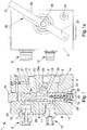
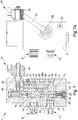
- the assembly 1 comprises a body 2 having a seat 3 communicating with at least a main port 4 and a secondary port 5, which are connectable to the braking system of a towing vehicle and able to receive a work fluid at a first and at a second pressure, respectively, an unloading port 6 connectable to an unloading tank, a control port 7 connectable to a first male coupling 8 of the towing vehicle, an additional port 9 connectable to a second male coupling 10 of the towing vehicle.
- the first and second male couplings 8 and 10 are connectable to respective female couplings (not shown in the illustrations), in turn connectable to the trailer, to convey the work fluid at the pressure required for operating the brakes of the trailer and at the pressure required for deactivating the parking and/or automatic brake of the trailer itself, respectively.
- a spool 11 is accommodated in a sliding manner, movable at least between the following working positions: a normal operating position, wherein the main port 4 and the secondary port 5 are put in communication with the control port 7 and with the additional port 9, respectively; a first emergency position, wherein the additional port 9 is put in communication with the unloading port 6, the main port 4 remaining in communication with the control port 7; and a second emergency position, wherein both the control port 7 and the additional port 9 are put in communication with the unloading port 6.
- the ports 4, 5, 6, 7 and 9 are put in communication with the seat 3 by means of relative channels 12, 13, 14, 15, 16 and 17 which face the seat itself by means of respective gaps.
- the main port 4 is put in communication with the seat 3 by means of a first and a second channel 12 and 13; the secondary port 5 is put in communication with the seat 3 by means of a third channel 14; the unloading port 6 is put in communication with the seat 3 by means of a fourth channel 15; the control port 7 is put in communication with the seat 3 by means of a fifth channel 16; the additional port 9 is put in communication with the seat 3 by means of a sixth channel 17.
- the spool 11 is then suitably shaped, or has a series of grooves, so as to open and close the connection between the gaps of the channels 12, 14, 15, 16 and 17 depending on the specific working positions.
- the ports 4, 5, 6 and the ports 7, 9, and consequently the relative gaps, are arranged opposite the seat 3 with respect to the spool 11.
- the ports 4, 5, 6 and the ports 7, 9 are defined on two opposite faces of the body 2.
- the seat 3 has an elongated shape and has two closing elements 18, 19 arranged at its opposite longitudinal extremities.
- the assembly 1 comprises first elastic means 20 placed between the stop element 19 of the seat 3 and the spool 11, which first elastic means are able to act on the spool itself to counteract the displacement thereof from the normal operating position to the first emergency position.
- connection channels 12 and 13 of which a first channel 12, along which a restriction 21 is arranged and the gap of which faces the side surface of the seat itself, and a second channel 13, communicating with a first thrust chamber 22 defined within the seat 3 and acting on the spool 11 on the opposite side of the first elastic means 20.
- the assembly 1 further comprises at least a first duct 23 for the transit of the work fluid, which is put in communication on one side with the first channel 12, downstream of the restriction 21 with respect to the advancement direction of the work fluid, and on the other with a second thrust chamber 24 acting on the spool 11 on the opposite side of the first thrust chamber 22.
- the first duct 23 is defined within the spool 11; alternative embodiments cannot however be ruled out wherein the first duct 23 is defined externally to the spool 11.
- first and second thrust chambers 22 and 24 act on the opposite extremities of the spool 11. More in particular, the first thrust chamber 22 is interposed between the stop element 18 and a first extremity of the spool 11 while the second thrust chamber 24 is interposed between the stop element 19 and a second extremity of the spool 11.
- the pressure in the first and second thrust chambers 22 and 24 is substantially the same and the first elastic means 20 are able to push the spool 11 up against the stop element 18.
- the first emergency position occurs the moment, e.g., following the breaking of a pipe in the hydraulic circuit of the trailer, the transit time of the work fluid for actuating the brakes of the trailer increases or increases its flow rate and a difference in pressure is produced at the ends of the restriction 21 which results in a difference in pressure between the first and the second thrust chambers 22 and 24, the pressure in the first thrust chamber 22 being greater than that in the second chamber 24, such as to determine the movement of the spool 11 in contrast to the first elastic means 20.
- the additional port 9 is no longer connected to the secondary port 5 but to the unloading port 6. This means that, following the zero setting of the pressure in the additional port, the parking and/or automatic brake of the trailer is activated
- the restriction 21 is sized in such a way as not to operate in conditions of normal operation.
- the assembly 1 also comprises second elastic means 25 placed between the stop element 19 and the body 2 and able to counteract the displacement of the spool 11 to the second emergency position.
- the second elastic means 25 are placed between the stop element 19 and a closing element 42 of the seat 3, locked together with the body 2.
- the spool 11 puts in communication the control port 7 with the unloading port 6 by means of a second duct 26 defined within the spool itself.
- the assembly 1 comprises command means 30 operable to command the displacement of the spool 11 from the normal operating position at least to the first emergency position.
- the command means 30 are also operable to command the displacement of the spool 11 to the second emergency position.
- the displacement of the spool 11 to the second emergency position is commanded when the hydraulic connection is to be made between the male and female couplings in the case of the former being under pressure.
- the command means 30 comprise at least a first lever 27 arranged externally to the body 2, connectable to the parking brake of the towing vehicle and able to interact with the spool 11.
- This first lever 27 is movable between a rest position, wherein the spool 11 is free to move due to the pressures present in the first and in the second thrust chambers 22 and 24, and a working position, wherein the spool 11 is pushed to the first emergency position.
- the first lever 27 is associated movable in rotation with the body 2 and is coupled to a pin 28 able to interact mechanically with the spool 11.
- the pin 28 e.g. has a tooth 28a which fits inside a groove obtained on the spool 11 and which is able to cooperate with an abutment element 29 defined by the spool itself.
- the command means 30 also comprise a second lever 31 arranged externally to the body 2, manually operable and able to interact with the spool 11.
- the second lever 31 is therefore operable by an operator to command the displacement of the spool 11 to the second emergency position.
- the second lever 31 is also associated movable in rotation with the body 2 and is coupled to the pin 28.
- the first lever 27 drives in rotation the second lever 31, by means of a guide element 32, during its stroke from the rest position to the working position, the pin 28 rotating by an angle corresponding to that made by the first lever itself.
- the second lever 31 is able to perform a further stroke with respect to the first lever 27, which remains stationary and resting against a stop element 33, during which the pin 28 rotates by a further angle.
- first and the second levers 27 and 31 are defined in a single body piece between them.
- the command means 30 comprise at least a solenoid valve 34 able to command the displacement of the spool 11 to the first emergency position.
- the solenoid valve 34 has an activation channel 35 communicating with a third thrust chamber 36 which acts on a thrust element 37 able to interact with the spool 11, where the thrust element 37 is movable in contrast to third elastic means 38.
- the solenoid valve 34 is operable to selectively put in communication the activation channel 35, and therefore the third thrust chamber 36, with the secondary port 5 or with the unloading port 6 by means of respective channels 39 and 40, respectively.
- the thrust element 37 comprises a small pin 41, inserted sliding through the stop element 18, able to interact with the spool 11 on the opposite side of the first elastic means 20.
- the thrust element 37 is movable between an inactive configuration, wherein the spool 11 is free to move between the normal operating position and the first emergency position, and an active configuration, wherein it operates on the spool itself to move it from the normal operating position to the first emergency position.
- the type of command sent from the solenoid valve itself to the thrust element 37 can be of the positive or negative type.
- the thrust element 37 is able to move from the inactive to the active configuration as a result of the increase in pressure in the third thrust chamber 36, in contrast to the third elastic means 38.
- the solenoid valve 34 puts in communication the third thrust chamber 36 with the secondary port 5
- the thrust element 37 is then pushed towards its active configuration
- the solenoid valve 34 puts in communication the third thrust chamber 36 with the unloading port 6
- the thrust element 37 returns to the inactive configuration due to the effect of the thrust of the third elastic means 38.
- the third elastic means 38 are placed between the stop element 18 and the thrust element 37, the third thrust chamber 36 being defined between the body 2 and the thrust element itself.
- the thrust element 37 is able to move from the active configuration to the inactive configuration following the increase in pressure in the third thrust chamber 36 in contrast to the third elastic means 38.
- the solenoid valve 34 puts in communication the third thrust chamber 36 with the secondary port 5
- the thrust element 37 moves from the active configuration, in which it is maintained by the third elastic means 38 in their rest configuration, to the inactive configuration, in contrast to the third elastic means themselves.
- the command means 30 also comprise the second lever 31, which, as in the embodiment of the figures 1 to 4 , is operable manually to command the displacement of the spool 11 to the second emergency configuration.
- the assembly 1 also comprises a piloting device 43 of the braking valve of the trailer (not illustrated in the figures) operatively connected to the first male coupling 8.
- the piloting device 43 comprises a command channel 44, connectable to the pump-brake of the towing vehicle (not illustrated in the figures), and a piloting channel 45, connectable to the braking valve of the trailer, wherein the command channel 44 and the piloting channel 45 are communicating with a further seat 46 within which one-way valve means 47 are arranged.
- valve means 47 are able to prevent the transit of the work fluid from the command channel 44 to the piloting channel 45 when the first male coupling 8 is disengaged from the relative female coupling and to allow the transit of the work fluid from the command channel 44 to the piloting channel 45 when the first male coupling 8 is inserted into the female coupling.
- valve means 47 comprise at least a shutter 48 movable between an opening configuration, wherein the command channel 44 and the piloting channel 45 are put in communication between them by means of the further seat 46, and a closing configuration, wherein the command channel 44 is isolated from the piloting channel 45.
- elastic means 49 are provided able to counteract the displacement of the shutter 48 from the closing configuration to the opening configuration.
- the piloting device 43 also comprises mechanical activation means 50 which are able to command the displacement of the shutter 48 from the closing configuration to the opening configuration as a result of the insertion of the first male coupling 8 within the relative female coupling.
- the activation means 50 are of the type of a rod having one extremity able to interact with the shutter 48 and the opposite extremity able to interact with the closing element 8a of the control channel 8b defined within the first male coupling 8.
- the rod 50 is movable between a rest position, in which it is spaced from the shutter element 48, which thus remains in the closing configuration, and an active position, in which it interacts with the shutter 48 to displace it to the opening configuration.
- the shutter 48 can in any case move from the closing configuration to the opening configuration following a difference in pressure between the piloting channel 45 and the command channel 44.
- the shutter 48 remains in the closing configuration thereby preventing the transit of the work fluid from the pump-brake of the towing vehicle to the brake valve of the trailer.
- the pressure in the towing vehicle cannot operate the brake valve of the trailer, but the work fluid under pressure along the piloting channel 45 can still be discharged towards the pump-brake of the towing vehicle bringing the shutter 48 to the opening configuration in contrast to the elastic means 49.
- the closing element 8a moves so as to open the control channel 8b causing the consequent displacement of the rod 50 to its active position.
- the rod 50 in turn interacts with the shutter 48 bringing it to the opening configuration.
- the work fluid under pressure in the command channel 44, and arriving from the pump-brake can flow away towards the piloting channel 45 and thus command the brake valve of the trailer.
- valve assembly forming the subject of the present invention allows discharging the pressure present in the additional port and in the control port, and consequently in the corresponding lines of the trailer, depending on the needs and conditions of emergency, such as the breaking of a pipe in the hydraulic circuit of the trailer or the need to make the hydraulic connection of the couplings in the presence of pressure inside the male couplings.
Landscapes
- Engineering & Computer Science (AREA)
- Transportation (AREA)
- Mechanical Engineering (AREA)
- Physics & Mathematics (AREA)
- Fluid Mechanics (AREA)
- Valves And Accessory Devices For Braking Systems (AREA)
Claims (15)
- Ensemble soupape (1), comprenant un corps (2) ayant un siège (3) communiquant avec au moins :- un orifice principal (4) et un orifice secondaire (5) pouvant être raccordés au système de freinage d'un véhicule de remorquage et capables de recevoir un premier et un second signal de pression, respectivement ;- un orifice de déchargement (6) pouvant être raccordé à un réservoir de déchargement ;- un orifice de commande (7) pouvant être raccordé à un premier couplage mâle (8) du véhicule de remorquage ;- un orifice supplémentaire (9) pouvant être raccordé à un second couplage mâle (10) du véhicule de remorquage ;à l'intérieur dudit siège (3) étant logé de manière coulissante au moins un tiroir (11), la soupape étant caractérisée en ce que le tiroir adopte au moins les positions suivantes :une position de fonctionnement normale, dans laquelle ledit orifice principal (4) et ledit orifice secondaire (5) sont mis en communication avec ledit orifice de commande (7) et avec ledit orifice supplémentaire (9), respectivement ;une première position d'urgence, dans laquelle ledit orifice supplémentaire (9) est mis en communication avec ledit orifice de déchargement (6), ledit orifice principal (4) restant en communication avec ledit orifice de commande (7) ;et une seconde position d'urgence, dans laquelle ledit orifice de commande (7) et ledit orifice supplémentaire (9) sont mis en communication avec ledit orifice de déchargement (6).
- Ensemble soupape (1) selon la revendication 1, caractérisé en ce qu'il comprend des premiers moyens élastiques (20) placés entre un élément d'arrêt (19) dudit siège (3) et ledit tiroir (11), lesdits premiers moyens élastiques (20) étant capables d'agir sur le tiroir lui-même pour contrer le déplacement de celui-ci vers la première position d'urgence, et en ce que, entre ledit orifice principal (4) et ledit siège (3), sont placés un premier canal de raccordement (12), ayant au moins une restriction (21), et un second canal de raccordement (13) communiquant avec une première chambre de poussée (22) définie à l'intérieur dudit siège (3) et agissant sur ledit tiroir (11) sur le côté opposé desdits premiers moyens élastiques (20), au moins une première conduite (23) étant définie, communiquant avec ledit premier canal (12), en aval de ladite restriction (21), et avec une deuxième chambre de poussée (24) agissant sur ledit tiroir (11) sur le côté opposé de ladite première chambre de poussée (22).
- Ensemble soupape (1) selon la revendication 2, caractérisé en ce que lesdites première et seconde chambres de poussée (22, 24) agissent sur les extrémités opposées dudit tiroir (11).
- Ensemble soupape (1) selon une ou plusieurs des revendications précédentes, caractérisé en ce qu'il comprend des deuxièmes moyens élastiques (25) placés entre ledit élément d'arrêt (19) et un élément de fermeture (42) dudit siège (3) et capables de contrer le déplacement dudit tiroir (11) vers la seconde position d'urgence, dans la première position d'urgence ledit tiroir (11) reposant sur ledit élément d'arrêt (19).
- Ensemble soupape (1) selon une ou plusieurs des revendications précédentes, caractérisé en ce qu'il comprend des moyens de commande (30) utilisables pour commander le déplacement dudit tiroir (11) au moins depuis la position de fonctionnement normale jusqu'à la première position d'urgence.
- Ensemble soupape (1) selon une ou plusieurs des revendications précédentes, caractérisé en ce que lesdits moyens de commande (30) sont utilisables pour commander le déplacement dudit tiroir (11) vers ladite seconde position d'urgence.
- Ensemble soupape (1) selon une ou plusieurs des revendications précédentes, caractérisé en ce que lesdits moyens de commande (30) comprennent au moins un premier levier (27) agencé de façon externe audit corps (2), pouvant être raccordé au frein de stationnement du véhicule de remorquage et capable d'interagir avec ledit tiroir (11), ledit premier levier (27) étant mobile entre une position de repos, dans laquelle ledit tiroir (11) est libre de se déplacer, et une position active, dans laquelle ledit tiroir (11) est poussé vers la première position d'urgence.
- Ensemble soupape (1) selon une ou plusieurs des revendications précédentes, caractérisé en ce que lesdits moyens de commande (30) comprennent au moins un second levier (31) agencé de façon externe audit corps (2), manuellement utilisables et capables d'interagir avec ledit tiroir (11), ledit second levier (31) étant mobile pour mettre le tiroir lui-même dans la seconde position d'urgence.
- Ensemble soupape (1) selon une ou plusieurs des revendications précédentes, caractérisé en ce qu'au moins un desdits premier et second leviers (27, 31) est associé, de façon mobile en rotation, audit corps (2) et est couplé à une goupille (28) capable d'interagir mécaniquement avec ledit tiroir (11).
- Ensemble soupape (1) selon une ou plusieurs des revendications précédentes, caractérisé en ce que lesdits premier et second leviers (27, 31) sont associés, de façon mobile en rotation, audit corps (2) et sont couplés à une goupille (28) capable d'interagir mécaniquement avec ledit tiroir (11), ledit premier levier (27) entraînant en rotation ledit second levier (31) durant sa course depuis la position de repos jusqu'à la position active, ladite goupille (28) entrant en rotation selon un angle prédéfini, et ledit second levier (31) étant capable de réaliser une course supplémentaire, durant laquelle ledit premier levier (27) reste stationnaire et ladite goupille (28) entre en rotation selon un angle supplémentaire.
- Ensemble soupape (1) selon une ou plusieurs des revendications précédentes, caractérisé en ce que lesdits moyens de commande (30) comprennent au moins une soupape à solénoïde (34) ayant un canal d'activation (35) communiquant avec une troisième chambre de poussée (36) agissant sur un élément de poussée (37) capable de coopérer avec ledit tiroir (11), ledit élément de poussée (37) étant mobile en contraste avec des troisièmes moyens élastiques (38), et utilisables pour sélectivement mettre en communication ledit canal d'activation (35) avec ledit orifice secondaire (5) ou avec ledit orifice de déchargement (6).
- Ensemble soupape (1) selon une ou plusieurs des revendications précédentes, caractérisé en ce que ledit élément de poussée (37) est capable d'agir sur ledit tiroir (11) sur le côté opposé desdits premiers moyens élastiques (20) et est mobile entre une configuration inactive, dans laquelle ledit tiroir est libre de se déplacer, et une configuration active, dans laquelle il fonctionne sur ledit tiroir (11) pour le déplacer depuis la position de fonctionnement normale jusqu'à ladite première position d'urgence.
- Ensemble soupape (1) selon une ou plusieurs des revendications précédentes, caractérisé en ce que ledit élément de poussée (37) est capable de se déplacer depuis la position inactive jusqu'à la configuration active en conséquence de l'augmentation de pression dans ladite troisième chambre de poussée (36) en contraste avec lesdits troisièmes moyens élastiques (38).
- Ensemble soupape (1) selon une ou plusieurs des revendications précédentes, caractérisé en ce que ledit élément de poussée (37) est capable de se déplacer depuis la configuration active jusqu'à la configuration inactive en conséquence de l'augmentation de pression dans ladite troisième chambre de poussée (36) en contraste avec lesdits troisièmes moyens élastiques (38).
- Ensemble (1) selon une ou plusieurs des revendications précédentes, caractérisé en ce qu'il comprend au moins un dispositif de pilotage (43) de soupape de freinage de la remorque, fonctionnellement raccordé audit premier couplage mâle (8).
Applications Claiming Priority (1)
| Application Number | Priority Date | Filing Date | Title |
|---|---|---|---|
| ITMO20140160 | 2014-05-30 |
Publications (2)
| Publication Number | Publication Date |
|---|---|
| EP3000672A1 EP3000672A1 (fr) | 2016-03-30 |
| EP3000672B1 true EP3000672B1 (fr) | 2019-04-24 |
Family
ID=51454827
Family Applications (1)
| Application Number | Title | Priority Date | Filing Date |
|---|---|---|---|
| EP15169982.4A Active EP3000672B1 (fr) | 2014-05-30 | 2015-05-29 | Système de soupape pour remorque |
Country Status (1)
| Country | Link |
|---|---|
| EP (1) | EP3000672B1 (fr) |
Families Citing this family (3)
| Publication number | Priority date | Publication date | Assignee | Title |
|---|---|---|---|---|
| IT201800006900A1 (it) * | 2018-07-03 | 2020-01-04 | Blocco valvolare | |
| EP3736189B1 (fr) * | 2019-03-26 | 2021-09-15 | Slanzi Oleodinamica S.r.l. | Distributeur et système oleodynamique de freinage pour véhicule agricole |
| IT202300023841A1 (it) * | 2023-11-10 | 2025-05-10 | Safim S R L | Dispositivo per il controllo della frenatura di un rimorchio a sospensione idraulica |
Family Cites Families (12)
| Publication number | Priority date | Publication date | Assignee | Title |
|---|---|---|---|---|
| DE1178309B (de) * | 1959-06-12 | 1964-09-17 | Italiana Magneti Marelli Soc P | Mit einem Anhaengersteuerventil fuer Druckluft-bremsanlagen kombinierte Vorrichtung zum Loesen und Anlegen der Bremsen |
| US3304131A (en) * | 1964-08-27 | 1967-02-14 | Wagner Electric Corp | Protector valve for a trailer brake system |
| DE2221399A1 (de) * | 1971-05-07 | 1972-11-23 | Magneti Marelli Spa | Automatischer Servoverteiler fuer pneumatische Bremsanlagen in Fahrzeugen |
| FR2275347A1 (fr) * | 1974-06-19 | 1976-01-16 | Unic Fiat Sa | Perfectionnement aux circuits pneumatiques de freinage entre un vehicule tracteur et une remorque |
| US4175588A (en) * | 1977-04-25 | 1979-11-27 | Midland-Ross Corporation | Air pressure brake arrangement for tractor and semi-trailer combinations |
| GB2045373B (en) * | 1979-03-09 | 1983-06-08 | Bendix Westinghouse Ltd | Trailer vehicle fluid pressure braking systems |
| DE4113671C2 (de) * | 1991-04-26 | 2001-10-11 | Wabco Gmbh & Co Ohg | Einrichtung für ein Anhängerbremsventil |
| DE19855679A1 (de) * | 1998-08-18 | 2000-02-24 | Mannesmann Rexroth Ag | Bremsventilanordnung |
| DE19857355A1 (de) * | 1998-12-11 | 2000-06-15 | Mannesmann Rexroth Ag | Anhängerbremsventil |
| US8297713B2 (en) * | 2007-04-18 | 2012-10-30 | Meritor Wabco Vehicle Control Systems | Full function tractor protection valve |
| DE102008048208B4 (de) * | 2008-09-20 | 2010-07-01 | Haldex Brake Products Gmbh | Bremseinrichtung für ein hydraulisch gebremstes Zugfahrzeug mit pneumatisch gebremstem Anhänger |
| EP2610122B1 (fr) * | 2011-12-28 | 2014-07-30 | KNORR-BREMSE Systeme für Nutzfahrzeuge GmbH | Tête de couplage |
-
2015
- 2015-05-29 EP EP15169982.4A patent/EP3000672B1/fr active Active
Non-Patent Citations (1)
| Title |
|---|
| None * |
Also Published As
| Publication number | Publication date |
|---|---|
| EP3000672A1 (fr) | 2016-03-30 |
Similar Documents
| Publication | Publication Date | Title |
|---|---|---|
| EP3000672B1 (fr) | Système de soupape pour remorque | |
| EP2853489B1 (fr) | Commande à double pression d'actionneur de frein de rotor pour aéronef à portance verticale | |
| US1905077A (en) | Safety means for hydraulic brakes | |
| DE112015005312T5 (de) | Fahrzeugbremsgerät | |
| EP3085590B1 (fr) | Unite' de controle pour un système de freinage d'un remorque | |
| EP3000631B1 (fr) | Système de connection tracteur-remorque | |
| EP3225473B1 (fr) | Dispositif pour la commande de freinage de remorque | |
| PH12021550569A1 (en) | Dual control emergency release system | |
| EP2952398B1 (fr) | Dispositif de soupape | |
| US3944286A (en) | Brake system including means for ensuring parking brake release | |
| US3999462A (en) | Brake delay valve | |
| GB2032544A (en) | Change-speed gear shiftable only on clutch disengagement | |
| EP2955073B1 (fr) | Système de connection tracteur-remorque | |
| EP3368385B1 (fr) | Dispositif de freinage pour remorques de machines agricoles | |
| EP3401176B1 (fr) | Engin pout contrôller les freins d'un remorque | |
| CN103935348A (zh) | 液压控制的自动复位制动结构及矿用自卸车 | |
| EP3064408B1 (fr) | Dispositif de reglage de freinage de remorque | |
| EP3611063B1 (fr) | Système de connexion de tracteur avec remorque | |
| US2760612A (en) | Clutch control apparatus | |
| US3065810A (en) | Auxiliary pump and controls for vehicles with hydraulic transmissions | |
| EP3085589B1 (fr) | Dispositif de vanne | |
| EP4054907B1 (fr) | Engin pour contrôler le freinage d'un remorque | |
| EP3165385B1 (fr) | Dispositif pour connexion entre vehicule et remorque | |
| EP3204277B1 (fr) | Dispositif d'équilibrage de pression pour systèmes hydrauliques de freinage | |
| EP3319848A1 (fr) | Dispositif d'actionnement d'une vanne pour le freinage d'une remorque |
Legal Events
| Date | Code | Title | Description |
|---|---|---|---|
| PUAI | Public reference made under article 153(3) epc to a published international application that has entered the european phase |
Free format text: ORIGINAL CODE: 0009012 |
|
| AK | Designated contracting states |
Kind code of ref document: A1 Designated state(s): AL AT BE BG CH CY CZ DE DK EE ES FI FR GB GR HR HU IE IS IT LI LT LU LV MC MK MT NL NO PL PT RO RS SE SI SK SM TR |
|
| AX | Request for extension of the european patent |
Extension state: BA ME |
|
| 17P | Request for examination filed |
Effective date: 20160928 |
|
| RBV | Designated contracting states (corrected) |
Designated state(s): AL AT BE BG CH CY CZ DE DK EE ES FI FR GB GR HR HU IE IS IT LI LT LU LV MC MK MT NL NO PL PT RO RS SE SI SK SM TR |
|
| 111Z | Information provided on other rights and legal means of execution |
Free format text: AL AT BE BG CH CY CZ DE DK EE ES FI FR GB GR HR HU IE IS IT LT LU LV MC MK MT NL NO PL PT RO RS SE SI SK SM TR Effective date: 20180208 |
|
| RAP1 | Party data changed (applicant data changed or rights of an application transferred) |
Owner name: SAFIM S.P.A. |
|
| GRAJ | Information related to disapproval of communication of intention to grant by the applicant or resumption of examination proceedings by the epo deleted |
Free format text: ORIGINAL CODE: EPIDOSDIGR1 |
|
| GRAP | Despatch of communication of intention to grant a patent |
Free format text: ORIGINAL CODE: EPIDOSNIGR1 |
|
| STAA | Information on the status of an ep patent application or granted ep patent |
Free format text: STATUS: REQUEST FOR EXAMINATION WAS MADE |
|
| GRAP | Despatch of communication of intention to grant a patent |
Free format text: ORIGINAL CODE: EPIDOSNIGR1 |
|
| STAA | Information on the status of an ep patent application or granted ep patent |
Free format text: STATUS: GRANT OF PATENT IS INTENDED |
|
| INTG | Intention to grant announced |
Effective date: 20181114 |
|
| GRAS | Grant fee paid |
Free format text: ORIGINAL CODE: EPIDOSNIGR3 |
|
| GRAA | (expected) grant |
Free format text: ORIGINAL CODE: 0009210 |
|
| STAA | Information on the status of an ep patent application or granted ep patent |
Free format text: STATUS: THE PATENT HAS BEEN GRANTED |
|
| GRAT | Correction requested after decision to grant or after decision to maintain patent in amended form |
Free format text: ORIGINAL CODE: EPIDOSNCDEC |
|
| AK | Designated contracting states |
Kind code of ref document: B1 Designated state(s): AL AT BE BG CH CY CZ DE DK EE ES FI FR GB GR HR HU IE IS IT LI LT LU LV MC MK MT NL NO PL PT RO RS SE SI SK SM TR |
|
| REG | Reference to a national code |
Ref country code: GB Ref legal event code: FG4D |
|
| RIN1 | Information on inventor provided before grant (corrected) |
Inventor name: MAMEI, ENRICO Inventor name: MAMEI, ERONNE Inventor name: MAMEI, ANDREA |
|
| REG | Reference to a national code |
Ref country code: CH Ref legal event code: EP Ref country code: CH Ref legal event code: PK Free format text: BERICHTIGUNGEN |
|
| REG | Reference to a national code |
Ref country code: AT Ref legal event code: REF Ref document number: 1123764 Country of ref document: AT Kind code of ref document: T Effective date: 20190515 Ref country code: IE Ref legal event code: FG4D |
|
| REG | Reference to a national code |
Ref country code: DE Ref legal event code: R096 Ref document number: 602015028728 Country of ref document: DE |
|
| RIN2 | Information on inventor provided after grant (corrected) |
Inventor name: MAMEI, ENRICO Inventor name: MAMEI, ERONNE Inventor name: MAMEI, ANDREA |
|
| REG | Reference to a national code |
Ref country code: DE Ref legal event code: R083 Ref document number: 602015028728 Country of ref document: DE |
|
| REG | Reference to a national code |
Ref country code: NL Ref legal event code: MP Effective date: 20190424 |
|
| REG | Reference to a national code |
Ref country code: LT Ref legal event code: MG4D |
|
| PG25 | Lapsed in a contracting state [announced via postgrant information from national office to epo] |
Ref country code: NL Free format text: LAPSE BECAUSE OF FAILURE TO SUBMIT A TRANSLATION OF THE DESCRIPTION OR TO PAY THE FEE WITHIN THE PRESCRIBED TIME-LIMIT Effective date: 20190424 |
|
| PG25 | Lapsed in a contracting state [announced via postgrant information from national office to epo] |
Ref country code: PT Free format text: LAPSE BECAUSE OF FAILURE TO SUBMIT A TRANSLATION OF THE DESCRIPTION OR TO PAY THE FEE WITHIN THE PRESCRIBED TIME-LIMIT Effective date: 20190824 Ref country code: ES Free format text: LAPSE BECAUSE OF FAILURE TO SUBMIT A TRANSLATION OF THE DESCRIPTION OR TO PAY THE FEE WITHIN THE PRESCRIBED TIME-LIMIT Effective date: 20190424 Ref country code: SE Free format text: LAPSE BECAUSE OF FAILURE TO SUBMIT A TRANSLATION OF THE DESCRIPTION OR TO PAY THE FEE WITHIN THE PRESCRIBED TIME-LIMIT Effective date: 20190424 Ref country code: AL Free format text: LAPSE BECAUSE OF FAILURE TO SUBMIT A TRANSLATION OF THE DESCRIPTION OR TO PAY THE FEE WITHIN THE PRESCRIBED TIME-LIMIT Effective date: 20190424 Ref country code: NO Free format text: LAPSE BECAUSE OF FAILURE TO SUBMIT A TRANSLATION OF THE DESCRIPTION OR TO PAY THE FEE WITHIN THE PRESCRIBED TIME-LIMIT Effective date: 20190724 Ref country code: FI Free format text: LAPSE BECAUSE OF FAILURE TO SUBMIT A TRANSLATION OF THE DESCRIPTION OR TO PAY THE FEE WITHIN THE PRESCRIBED TIME-LIMIT Effective date: 20190424 Ref country code: HR Free format text: LAPSE BECAUSE OF FAILURE TO SUBMIT A TRANSLATION OF THE DESCRIPTION OR TO PAY THE FEE WITHIN THE PRESCRIBED TIME-LIMIT Effective date: 20190424 Ref country code: LT Free format text: LAPSE BECAUSE OF FAILURE TO SUBMIT A TRANSLATION OF THE DESCRIPTION OR TO PAY THE FEE WITHIN THE PRESCRIBED TIME-LIMIT Effective date: 20190424 |
|
| PG25 | Lapsed in a contracting state [announced via postgrant information from national office to epo] |
Ref country code: PL Free format text: LAPSE BECAUSE OF FAILURE TO SUBMIT A TRANSLATION OF THE DESCRIPTION OR TO PAY THE FEE WITHIN THE PRESCRIBED TIME-LIMIT Effective date: 20190424 Ref country code: RS Free format text: LAPSE BECAUSE OF FAILURE TO SUBMIT A TRANSLATION OF THE DESCRIPTION OR TO PAY THE FEE WITHIN THE PRESCRIBED TIME-LIMIT Effective date: 20190424 Ref country code: BG Free format text: LAPSE BECAUSE OF FAILURE TO SUBMIT A TRANSLATION OF THE DESCRIPTION OR TO PAY THE FEE WITHIN THE PRESCRIBED TIME-LIMIT Effective date: 20190724 Ref country code: GR Free format text: LAPSE BECAUSE OF FAILURE TO SUBMIT A TRANSLATION OF THE DESCRIPTION OR TO PAY THE FEE WITHIN THE PRESCRIBED TIME-LIMIT Effective date: 20190725 Ref country code: LV Free format text: LAPSE BECAUSE OF FAILURE TO SUBMIT A TRANSLATION OF THE DESCRIPTION OR TO PAY THE FEE WITHIN THE PRESCRIBED TIME-LIMIT Effective date: 20190424 |
|
| REG | Reference to a national code |
Ref country code: DE Ref legal event code: R119 Ref document number: 602015028728 Country of ref document: DE |
|
| REG | Reference to a national code |
Ref country code: AT Ref legal event code: MK05 Ref document number: 1123764 Country of ref document: AT Kind code of ref document: T Effective date: 20190424 |
|
| REG | Reference to a national code |
Ref country code: CH Ref legal event code: PL |
|
| PG25 | Lapsed in a contracting state [announced via postgrant information from national office to epo] |
Ref country code: IS Free format text: LAPSE BECAUSE OF FAILURE TO SUBMIT A TRANSLATION OF THE DESCRIPTION OR TO PAY THE FEE WITHIN THE PRESCRIBED TIME-LIMIT Effective date: 20190824 |
|
| PG25 | Lapsed in a contracting state [announced via postgrant information from national office to epo] |
Ref country code: CH Free format text: LAPSE BECAUSE OF NON-PAYMENT OF DUE FEES Effective date: 20190531 Ref country code: AT Free format text: LAPSE BECAUSE OF FAILURE TO SUBMIT A TRANSLATION OF THE DESCRIPTION OR TO PAY THE FEE WITHIN THE PRESCRIBED TIME-LIMIT Effective date: 20190424 Ref country code: LI Free format text: LAPSE BECAUSE OF NON-PAYMENT OF DUE FEES Effective date: 20190531 Ref country code: DK Free format text: LAPSE BECAUSE OF FAILURE TO SUBMIT A TRANSLATION OF THE DESCRIPTION OR TO PAY THE FEE WITHIN THE PRESCRIBED TIME-LIMIT Effective date: 20190424 Ref country code: CZ Free format text: LAPSE BECAUSE OF FAILURE TO SUBMIT A TRANSLATION OF THE DESCRIPTION OR TO PAY THE FEE WITHIN THE PRESCRIBED TIME-LIMIT Effective date: 20190424 Ref country code: EE Free format text: LAPSE BECAUSE OF FAILURE TO SUBMIT A TRANSLATION OF THE DESCRIPTION OR TO PAY THE FEE WITHIN THE PRESCRIBED TIME-LIMIT Effective date: 20190424 Ref country code: RO Free format text: LAPSE BECAUSE OF FAILURE TO SUBMIT A TRANSLATION OF THE DESCRIPTION OR TO PAY THE FEE WITHIN THE PRESCRIBED TIME-LIMIT Effective date: 20190424 Ref country code: SK Free format text: LAPSE BECAUSE OF FAILURE TO SUBMIT A TRANSLATION OF THE DESCRIPTION OR TO PAY THE FEE WITHIN THE PRESCRIBED TIME-LIMIT Effective date: 20190424 Ref country code: MC Free format text: LAPSE BECAUSE OF FAILURE TO SUBMIT A TRANSLATION OF THE DESCRIPTION OR TO PAY THE FEE WITHIN THE PRESCRIBED TIME-LIMIT Effective date: 20190424 |
|
| REG | Reference to a national code |
Ref country code: BE Ref legal event code: MM Effective date: 20190531 |
|
| PG25 | Lapsed in a contracting state [announced via postgrant information from national office to epo] |
Ref country code: LU Free format text: LAPSE BECAUSE OF NON-PAYMENT OF DUE FEES Effective date: 20190529 Ref country code: SM Free format text: LAPSE BECAUSE OF FAILURE TO SUBMIT A TRANSLATION OF THE DESCRIPTION OR TO PAY THE FEE WITHIN THE PRESCRIBED TIME-LIMIT Effective date: 20190424 |
|
| PLBE | No opposition filed within time limit |
Free format text: ORIGINAL CODE: 0009261 |
|
| STAA | Information on the status of an ep patent application or granted ep patent |
Free format text: STATUS: NO OPPOSITION FILED WITHIN TIME LIMIT |
|
| GBPC | Gb: european patent ceased through non-payment of renewal fee |
Effective date: 20190724 |
|
| PG25 | Lapsed in a contracting state [announced via postgrant information from national office to epo] |
Ref country code: TR Free format text: LAPSE BECAUSE OF FAILURE TO SUBMIT A TRANSLATION OF THE DESCRIPTION OR TO PAY THE FEE WITHIN THE PRESCRIBED TIME-LIMIT Effective date: 20190424 |
|
| 26N | No opposition filed |
Effective date: 20200127 |
|
| PG25 | Lapsed in a contracting state [announced via postgrant information from national office to epo] |
Ref country code: GB Free format text: LAPSE BECAUSE OF NON-PAYMENT OF DUE FEES Effective date: 20190724 Ref country code: DE Free format text: LAPSE BECAUSE OF NON-PAYMENT OF DUE FEES Effective date: 20191203 Ref country code: IE Free format text: LAPSE BECAUSE OF NON-PAYMENT OF DUE FEES Effective date: 20190529 |
|
| PG25 | Lapsed in a contracting state [announced via postgrant information from national office to epo] |
Ref country code: SI Free format text: LAPSE BECAUSE OF FAILURE TO SUBMIT A TRANSLATION OF THE DESCRIPTION OR TO PAY THE FEE WITHIN THE PRESCRIBED TIME-LIMIT Effective date: 20190424 Ref country code: BE Free format text: LAPSE BECAUSE OF NON-PAYMENT OF DUE FEES Effective date: 20190531 |
|
| PG25 | Lapsed in a contracting state [announced via postgrant information from national office to epo] |
Ref country code: FR Free format text: LAPSE BECAUSE OF NON-PAYMENT OF DUE FEES Effective date: 20190624 |
|
| PG25 | Lapsed in a contracting state [announced via postgrant information from national office to epo] |
Ref country code: CY Free format text: LAPSE BECAUSE OF FAILURE TO SUBMIT A TRANSLATION OF THE DESCRIPTION OR TO PAY THE FEE WITHIN THE PRESCRIBED TIME-LIMIT Effective date: 20190424 |
|
| PG25 | Lapsed in a contracting state [announced via postgrant information from national office to epo] |
Ref country code: HU Free format text: LAPSE BECAUSE OF FAILURE TO SUBMIT A TRANSLATION OF THE DESCRIPTION OR TO PAY THE FEE WITHIN THE PRESCRIBED TIME-LIMIT; INVALID AB INITIO Effective date: 20150529 Ref country code: MT Free format text: LAPSE BECAUSE OF FAILURE TO SUBMIT A TRANSLATION OF THE DESCRIPTION OR TO PAY THE FEE WITHIN THE PRESCRIBED TIME-LIMIT Effective date: 20190424 |
|
| PG25 | Lapsed in a contracting state [announced via postgrant information from national office to epo] |
Ref country code: MK Free format text: LAPSE BECAUSE OF FAILURE TO SUBMIT A TRANSLATION OF THE DESCRIPTION OR TO PAY THE FEE WITHIN THE PRESCRIBED TIME-LIMIT Effective date: 20190424 |
|
| P01 | Opt-out of the competence of the unified patent court (upc) registered |
Effective date: 20230527 |
|
| PGFP | Annual fee paid to national office [announced via postgrant information from national office to epo] |
Ref country code: IT Payment date: 20250520 Year of fee payment: 11 |