EP3368385B1 - Dispositif de freinage pour remorques de machines agricoles - Google Patents
Dispositif de freinage pour remorques de machines agricoles Download PDFInfo
- Publication number
- EP3368385B1 EP3368385B1 EP16809169.2A EP16809169A EP3368385B1 EP 3368385 B1 EP3368385 B1 EP 3368385B1 EP 16809169 A EP16809169 A EP 16809169A EP 3368385 B1 EP3368385 B1 EP 3368385B1
- Authority
- EP
- European Patent Office
- Prior art keywords
- line
- valve
- chamber
- automatic
- elastic means
- Prior art date
- Legal status (The legal status is an assumption and is not a legal conclusion. Google has not performed a legal analysis and makes no representation as to the accuracy of the status listed.)
- Active
Links
Images


Classifications
-
- B—PERFORMING OPERATIONS; TRANSPORTING
- B60—VEHICLES IN GENERAL
- B60T—VEHICLE BRAKE CONTROL SYSTEMS OR PARTS THEREOF; BRAKE CONTROL SYSTEMS OR PARTS THEREOF, IN GENERAL; ARRANGEMENT OF BRAKING ELEMENTS ON VEHICLES IN GENERAL; PORTABLE DEVICES FOR PREVENTING UNWANTED MOVEMENT OF VEHICLES; VEHICLE MODIFICATIONS TO FACILITATE COOLING OF BRAKES
- B60T7/00—Brake-action initiating means
- B60T7/12—Brake-action initiating means for automatic initiation; for initiation not subject to will of driver or passenger
- B60T7/20—Brake-action initiating means for automatic initiation; for initiation not subject to will of driver or passenger specially for trailers, e.g. in case of uncoupling of or overrunning by trailer
-
- B—PERFORMING OPERATIONS; TRANSPORTING
- B60—VEHICLES IN GENERAL
- B60T—VEHICLE BRAKE CONTROL SYSTEMS OR PARTS THEREOF; BRAKE CONTROL SYSTEMS OR PARTS THEREOF, IN GENERAL; ARRANGEMENT OF BRAKING ELEMENTS ON VEHICLES IN GENERAL; PORTABLE DEVICES FOR PREVENTING UNWANTED MOVEMENT OF VEHICLES; VEHICLE MODIFICATIONS TO FACILITATE COOLING OF BRAKES
- B60T17/00—Component parts, details, or accessories of power brake systems not covered by groups B60T8/00, B60T13/00 or B60T15/00, or presenting other characteristic features
- B60T17/18—Safety devices; Monitoring
Definitions
- the present invention relates to a braking device for trailers of agricultural machines.
- the towing vehicles are connected to their respective trailer by means of a connection device that allows placing the respective braking systems in communication to one another, in such a way that the braking of the towing vehicle operated by the operator also causes the braking of the towed trailer.
- the braking system of the trailer is therefore driven by the braking system of the tractor in order to synchronize the braking forces acting on the same.
- GB 2 492 124 A discloses a vehicle braking system having an electrically operable emergency braking override valve for avoiding the emergency brake applying valve from being vented.
- connection device between the towing vehicle and its trailer must comprise a portion connectable to the trailer and having a pair of female couplings intended to receive the corresponding male couplings connectable to the towing vehicle.
- first female coupling communicating with a control line connectable to the braking system of the trailer and a second female coupling communicating with an additional line connectable to the parking and/or automatic brake of the trailer itself.
- the additional line is therefore the line that allows applying the on-off braking of the trailer in the case of an emergency, or in the case of detachment of the trailer from the towing vehicle.
- the main aim of the present invention is to provide a braking device for trailers of agricultural machines, which allows the use of automatic and/or parking brakes with springs on any type of trailer and irrespectively of the connections present on the corresponding towing vehicle.
- one object of the present invention is to permit the manual release of the automatic and/or parking brake even when the towing vehicle is not connected to the corresponding trailer.
- Another object of the present invention is to provide a braking device for trailers of agricultural machines which allows to overcome the mentioned drawbacks of the prior art within the ambit of a simple, rational, easy, effective to use and affordable solution.
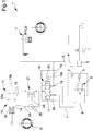
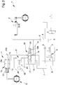
- reference numeral 1 globally indicates a braking device for trailers of agricultural machines.
- the device 1 connectable to the trailer of an agricultural machine or other operating machine, comprises a first and a second female coupling, schematized in the figures by the reference numbers 2 and 3, associable with a trailer and adapted to receive related male couplings, schematized in the figures by the reference numbers 4 and 5, associable with a towing vehicle and adapted to send a pressurized fluid inside the respective female couplings.
- the device 1 then comprises at least one control line 6 communicating with the first female coupling 2 and connectable to the braking system F of the trailer, at least one additional line 7 communicating with the second female coupling 3 and connectable to the automatic and/or parking brake G of the trailer.
- the device 1 also comprises at least one auxiliary line 8 connectable to the additional line 7 following the detachment of the second female coupling 3 from its male coupling 5.
- first valve means 9 are adapted to isolate and place in communication the additional line 7 with the auxiliary line 8 following the coupling and the uncoupling, respectively, of the second female coupling 3 from its male coupling 5.
- the auxiliary line 8 is connected to the control line 6 by means of second one-way valve means 10 adapted to allow only the outflow of the working fluid from the auxiliary line 8 to the control line 6 following a pressure difference between them.
- the device 1 comprises, therefore, also a command device 11 of the automatic and/or parking brake G.
- the command device 11 comprises first elastic means 12 adapted to activate the automatic and/or parking brake G and at least one fluid-operated cylinder 13 adapted to interact with the first elastic means themselves.
- the first elastic means 12 are adapted to actuate the command of the automatic and/or parking brake G for the activation of the same.
- the cylinder 13 in turn comprises a body 13a inside which is housed in a sliding manner one rod 13b, which interacts with the first elastic means 12 and on which at least a first chamber 14 operates in contrast to the action of first elastic means 12 to cause the release of the automatic and/or parking brake G.
- the cylinder 13 also comprises a second chamber 15, which operates on the rod 13b on the opposite side of the first chamber 14, or in the same direction as the action of the first elastic means 12.
- the cylinder 13 is of the double-acting type and the operational surfaces of the rod 13b facing the chambers 14 and 15 are substantially equal to each other.
- the cylinder 13 is connected in a fluid-operated manner to the service braking system F of the trailer.
- the automatic and/or parking brake G also performs the service brake function.
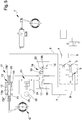
- the rod 13b comprises a first and a second portion, respectively identified with the reference numbers 13b' and 13b", movable reciprocally between them.
- the first portion 13b' is adapted to interact with the first elastic means 12 depending on the pressure present in the chambers 14, 15, and a second portion 13b" is adapted to interact with the automatic and/or parking brake G to command the activation/deactivation thereof and activate also the service braking.
- a third chamber 22 communicating with the control line 6 and adapted to move the second portion 13b" to command the activation of the automatic and/or parking brake G (which, as mentioned above, operates in this embodiment also as a service brake) following the increase in pressure along said control line 6.
- the third chamber 22 is placed in communication with the control line 6 through a canal 23 formed in the first portion 13b'. It follows, therefore, that in this second embodiment, the automatic and/or parking brake G, which also operates as a service brake, is activated following the increase in pressure along the control line 6 irrespective of the pressure present in the chambers 14 and 15.
- a valve 16 which has a spool 17 movable between a normal operation configuration, in which it places the first chamber 14 in communication with the additional line 7 and the second chamber 15 with a lower pressure line so as to allow draining the working fluid contained in it and permit the deactivation of the automatic and/or parking brake G, and a braking configuration, in which it places the first and the second chamber 14, 15 in communication between them, so as to make ineffective the action of the rod 13b (which is therefore floating) on the first elastic means 12 which by expanding activate the automatic and/or parking brake G.
- the second chamber 15 in the normal operation configuration, is placed in communication with the auxiliary line 8, so that the working fluid contained therein drains along the control line 6, via the second valve means 10, when this is at a lower pressure, while in the braking configuration, both chambers 14, 15 are placed in communication with the auxiliary line 8.
- valve 16 comprises a body 18 which defines a seat 19 inside which the spool 17 is housed in a sliding manner.
- the seat 19 has four openings communicating with the additional line 7, with the auxiliary line 8, with the first chamber 14 and with the second chamber 15, respectively.
- spool 17 On the spool 17 operate two compartments, opposite to one another, for example defined inside the seat 19 between the ending parts of the spool itself and the body 18, of which a first compartment 19a placed in communication with the additional line 7 and adapted to push the spool 17 towards the normal operation configuration and a second compartment 19b, inside which are housed second elastic means 20, operating in a direction opposite to the first compartment 19a.
- the second compartment 19b is placed in communication with the auxiliary line 8, to drain and receive the working fluid, which operates therefore on the spool 17 in the same direction as the action exerted by the second elastic means 20.
- the spool 17 is therefore adapted to move towards the normal operation configuration following the connection of the female couplings 2, 3 to the corresponding male couplings 4, 5 and the pressurization of the additional line 7 and to move towards the braking configuration following the uncoupling between them, in such case the connection occurring between the additional line 7 and the auxiliary line 8 by means of the first valve means 9 and, therefore, the connection between the compartments 19a and 19b.
- the spool 17 is adapted to substantially move the same volume of working fluid in both directions.
- the device 1 comprises pumping means 21 interposed between the command device 11 and the valve 16, which are manually operable to supply the first chamber 14 of the cylinder 13 so as to release the automatic and/or parking brake G even when the trailer is detached from the towing vehicle.
- the pumping means 21 are of the double acting type, while in the embodiments of Figures 4 and 5 , the pumping means 21 are of the single acting type.
- a supply/drain channel 25 interposed between the valve 16 and the command device 11 and arranged in parallel to the pumping means 21.
- the supply/drain channel 25 allows the inflow and outflow of the working fluid from the first chamber 14 towards the valve 16 following the attachment and the detachment, respectively, of the trailer from the towing vehicle and, therefore, the connection between the additional line 7 and the auxiliary line 8.
- a valve device 26 manually operable to move it from an open configuration, in which it allows the passage of the working fluid, to a closed configuration, in which it prevents the passage of the working fluid.
- valve device 26 is brought to the closed configuration when the second female coupling 3 is separated from its male coupling 5 and there is the need to pressurize the first chamber 14 to compress the first elastic means 12 and thus release the automatic and/or parking brake G.
- the valve device 26 By bringing the valve device 26 to the closed configuration it is in fact possible to supply the first chamber 14 by means of the pumping means 21.
- the valve device 26 comprises opening means, e.g. of the spring type, (not visible in detail in the figures) operatively connected to the additional line 7 and adapted to return the valve device itself from the closed configuration to the open configuration upon reaching a predefined pressure of the working fluid along the additional line 7.
- opening means e.g. of the spring type, (not visible in detail in the figures) operatively connected to the additional line 7 and adapted to return the valve device itself from the closed configuration to the open configuration upon reaching a predefined pressure of the working fluid along the additional line 7.
- valve device 26 can be operable automatically following the accidental detachment of the trailer from the towing vehicle, or following the detachment of the female couplings 2, 3 from the relative male couplings 4, 5.
- the operation of the present invention is as follows.
- the additional line 7 receives the working fluid under pressure, between 15 bar and 35 bar, and the first valve means 9 isolate the additional line itself from the auxiliary line 8.
- the working fluid coming from the additional line 7 enters therefore the first chamber 14 of the cylinder 13 so as to cause it to move in contrast to the first elastic means 12.
- the compression of the first elastic means 12 causes the deactivation of the automatic and/or parking brake G.
- the working fluid in the second chamber 15 of the cylinder 13 and in the second compartment 19b flows out through the auxiliary line 8 and drains, via the second valve means 10, on the control line 6 following a pressure difference between the two lines. This pressure difference occurs at least when the pressure of the working fluid that supplies the service braking system F drops to zero.
- the first valve means 9 change their state by placing the additional line 7 in mutual communication with the auxiliary line 8.
- the automatic and/or parking brake G is activated following the pressurization of the control line 6, thus operating also as a service brake.
- the pressurized working fluid present along the control line 6 enters the third chamber 22 by exerting a force on the second portion 13b" so as to push it away from the first portion 13b' and actuate the automatic and/or parking brake G.
- Figure 5 shows the operation configuration in which the automatic and/or parking brake G which, as discussed above, also performs the function of service brake, is activated due to the effect of the pressure present along the control line 6 despite the valve 16 is in the normal operation configuration and the first elastic means are, therefore, compressed.
- the described invention achieves the intended objects and in particular the fact is underlined that the braking device making the subject of the present invention allows the use of automatic and/or parking brakes with springs on any trailer, and irrespectively of the type of dual-line braking system of its towing vehicle.
Landscapes
- Engineering & Computer Science (AREA)
- Transportation (AREA)
- Mechanical Engineering (AREA)
- Braking Systems And Boosters (AREA)
- Regulating Braking Force (AREA)
- Sowing (AREA)
- Soil Working Implements (AREA)
- Control Of Driving Devices And Active Controlling Of Vehicle (AREA)
Claims (14)
- Dispositif de freinage (1) pour remorques de machines agricoles, comprenant :- un premier et un second organe d'accouplement femelle (2, 3) pouvant être associés à une remorque et capables de recevoir des organes d'accouplement mâles (4, 5) relatifs pouvant être associés à un véhicule de remorquage pour envoyer un fluide sous pression à l'intérieur des organes d'accouplement femelles (2, 3) respectifs ;- au moins une conduite de commande (6) communiquant avec ledit premier organe d'accouplement femelle (2) et pouvant être raccordée au système de freinage de service (F) de la remorque, au moins une conduite supplémentaire (7) communiquant avec ledit second organe d'accouplement femelle (3) et pouvant être raccordée au frein automatique et/ou de stationnement (G) de la remorque ;- un dispositif de commande (11) du frein automatique et/ou de stationnement (G) de la remorque comprenant un premier moyen élastique (12) capable d'activer le frein automatique et/ou de stationnement lui-même et au moins un cylindre actionné par fluide (13) capable d'interagir avec le premier moyen élastique lui-même ; ledit cylindre actionné par fluide (13) ayant au moins une première chambre (14) capable de déplacer la tige (13b) relative dans la direction opposée à l'action dudit premier moyen élastique (12) ;caractérisé en ce que ledit cylindre (13) comporte au moins une deuxième chambre (15) agissant sur le côté opposé de ladite première chambre (14) et capable de déplacer la tige (13b) respective dans la même direction que l'action dudit premier moyen élastique (12) ;
et en ce qu'il comprend
au moins une soupape (16) intercalée entre lesdits organes d'accouplement femelles (2, 3) et ledit dispositif de commande (11) et ayant une bobine (17) mobile entre une configuration de freinage, dans laquelle lesdites première et deuxième chambres (14, 15) sont mutuellement placées en communication, permettant audit premier moyen élastique (12) de s'étendre librement, et une configuration de fonctionnement normal, dans laquelle ladite première chambre (14) est placée en communication avec ladite conduite supplémentaire (7) et ladite deuxième chambre (15) peut être raccordée à une conduite de pression plus basse de manière à comprimer ledit premier moyen élastique (12) afin de relâcher le frein automatique et/ou de stationnement (G). - Dispositif (1) selon la revendication 1, caractérisé en ce que sur ladite bobine (17) agissent, depuis des côtés opposés, un premier compartiment (19a) communiquant avec ladite conduite supplémentaire (7) et capable de la pousser vers la configuration de fonctionnement normal et un second compartiment (19b) dans lequel est logé un second moyen élastique (20).
- Dispositif (1) selon la revendication 1 ou 2, caractérisé en ce qu'il comprend au moins une conduite auxiliaire (8) pouvant être raccordée à ladite conduite supplémentaire (7) à la suite du détachement dudit second organe d'accouplement femelle (3) vis-à-vis de l'organe d'accouplement mâle (5) relatif, où lesdites première et deuxième chambres (14, 15) sont placées en communication avec ladite conduite auxiliaire (8) avec ladite soupape (16) dans la configuration de freinage et sont placées en communication avec ladite conduite supplémentaire (7) et avec ladite conduite auxiliaire (8) respectivement, avec ladite soupape (16) dans la configuration de fonctionnement normal.
- Dispositif (1) selon la revendication 3, caractérisé en ce que ladite conduite auxiliaire (8) communique avec ledit second compartiment (19b), ladite bobine (17) se déplaçant vers la configuration de fonctionnement normal à la suite du raccordement dudit second organe d'accouplement femelle (3) à l'organe d'accouplement mâle (5) relatif, avec ladite conduite supplémentaire (7) sous pression, et se déplaçant vers la configuration de freinage à la suite de désaccouplement de celle-ci avec ladite conduite auxiliaire (8) communiquant avec ladite conduite supplémentaire (7).
- Dispositif (1) selon la revendication 3 ou 4, caractérisé en ce qu'il comprend un premier moyen de soupape (9) capable d'isoler et de placer en communication ladite conduite supplémentaire (7) et ladite conduite auxiliaire (8) respectivement, à la suite de l'accouplement et du désaccouplement du second organe d'accouplement femelle (3) vis-à-vis de l'organe d'accouplement mâle (5) relatif.
- Dispositif (1) selon une ou plusieurs des revendications 2 à 5, caractérisé en ce que ladite conduite auxiliaire (8) est raccordée à ladite conduite de commande (6) à l'aide d'un second moyen de soupape unidirectionnel (10).
- Dispositif (1) selon une ou plusieurs des revendications précédentes, caractérisé en ce que ledit cylindre actionné par fluide (13) est du type à double action et en ce que les surfaces fonctionnelles de ladite tige (13b) faisant face auxdites chambres (14, 15) sont sensiblement égales entre elles.
- Dispositif (1) selon une ou plusieurs des revendications précédentes, caractérisé en ce qu'il comprend un moyen de pompage (21) interposé entre ledit dispositif de commande (11) et ladite soupape (16) et pouvant être manuellement actionné pour alimenter ladite première chambre (14) du cylindre actionné par fluide (13) et en ce qu'il comprend au moins un canal d'alimentation/d'évacuation (25) interposé entre ladite soupape (16) et ledit dispositif de commande (11) et agencé parallèlement audit moyen de pompage (21).
- Dispositif (1) selon la revendication 8, caractérisé en ce que ledit moyen de pompage (21) est du type à double action.
- Dispositif (1) selon la revendication 8 ou 9, caractérisé en ce qu'il comprend au moins un dispositif de soupape (26) agencé le long dudit canal d'alimentation/d'évacuation (25) et pouvant être manuellement actionné pour le déplacer d'une configuration ouverte à une configuration fermée.
- Dispositif (1) selon la revendication 10, caractérisé en ce que ledit dispositif de soupape (26) comprend un moyen d'ouverture fonctionnellement raccordé à ladite conduite supplémentaire (7) et capable de ramener le dispositif de soupape lui-même de la configuration fermée à la configuration ouverte lors de l'atteinte d'une pression prédéfinie du fluide de travail le long de ladite conduite supplémentaire (7).
- Dispositif (1) selon la revendication 10 ou 11, caractérisé en ce que ledit dispositif de soupape (26) peut fonctionner à la suite du détachement accidentel desdits organes d'accouplement femelles (2, 3) vis-à-vis des organes d'accouplement mâles (4, 5) relatifs.
- Dispositif (1) selon une ou plusieurs des revendications précédentes, caractérisé en ce que ledit cylindre (13) est raccordé d'une manière actionnée par fluide audit système de freinage de service (F) de la remorque.
- Dispositif (1) selon la revendication 13, caractérisé en ce que ladite tige (13b) comprend une première partie (13b') qui interagit avec ledit premier moyen élastique (12) et une seconde partie (13b") qui interagit avec le frein automatique et/ou de stationnement (G) et qui est mobile par rapport à la première partie elle-même ; entre ladite première et ladite seconde partie (13b', 13b") étant définie une troisième chambre (22) communiquant avec ladite conduite de commande (6) et capable de déplacer ladite seconde partie (13b") pour commander l'activation du frein automatique et/ou de stationnement (G) à la suite de l'augmentation de la pression le long de ladite conduite de commande (6).
Applications Claiming Priority (2)
| Application Number | Priority Date | Filing Date | Title |
|---|---|---|---|
| ITUB2015A005308A ITUB20155308A1 (it) | 2015-10-30 | 2015-10-30 | Dispositivo di frenatura per rimorchi di macchine agricole |
| PCT/IB2016/056434 WO2017072672A1 (fr) | 2015-10-30 | 2016-10-26 | Dispositif de freinage pour remorques de machines agricoles |
Publications (2)
| Publication Number | Publication Date |
|---|---|
| EP3368385A1 EP3368385A1 (fr) | 2018-09-05 |
| EP3368385B1 true EP3368385B1 (fr) | 2019-08-28 |
Family
ID=55410080
Family Applications (1)
| Application Number | Title | Priority Date | Filing Date |
|---|---|---|---|
| EP16809169.2A Active EP3368385B1 (fr) | 2015-10-30 | 2016-10-26 | Dispositif de freinage pour remorques de machines agricoles |
Country Status (3)
| Country | Link |
|---|---|
| EP (1) | EP3368385B1 (fr) |
| IT (1) | ITUB20155308A1 (fr) |
| WO (1) | WO2017072672A1 (fr) |
Families Citing this family (2)
| Publication number | Priority date | Publication date | Assignee | Title |
|---|---|---|---|---|
| IT201700052010A1 (it) * | 2017-05-12 | 2018-11-12 | Safim S P A | Dispositivo di controllo di una valvola freno-rimorchio, collegabile all’impianto di frenatura di un rimorchio, per veicoli di traino con trasmissione idrostatica provvista di almeno una pompa a cilindrata variabile |
| IT201800010083A1 (it) * | 2018-11-06 | 2020-05-06 | Safim S P A | Dispositivo per il controllo della frenatura di un rimorchio |
Family Cites Families (2)
| Publication number | Priority date | Publication date | Assignee | Title |
|---|---|---|---|---|
| DE102007047691A1 (de) * | 2007-10-05 | 2009-04-09 | Wabco Gmbh | Elektropneumatischer Feststellbremsmodulator zur Steuerung einer Feststellbremsfunktion von Bremsen eines Anhängefahrzeugs in einem Fahrzeugzug |
| GB2492124B (en) * | 2011-06-22 | 2017-08-09 | Haldex Brake Prod Ab | Vehicle braking system |
-
2015
- 2015-10-30 IT ITUB2015A005308A patent/ITUB20155308A1/it unknown
-
2016
- 2016-10-26 WO PCT/IB2016/056434 patent/WO2017072672A1/fr not_active Ceased
- 2016-10-26 EP EP16809169.2A patent/EP3368385B1/fr active Active
Non-Patent Citations (1)
| Title |
|---|
| None * |
Also Published As
| Publication number | Publication date |
|---|---|
| EP3368385A1 (fr) | 2018-09-05 |
| WO2017072672A1 (fr) | 2017-05-04 |
| ITUB20155308A1 (it) | 2017-04-30 |
Similar Documents
| Publication | Publication Date | Title |
|---|---|---|
| AU2016401332A1 (en) | Vehicle coupling lines storage and control arrangement | |
| EP3368385B1 (fr) | Dispositif de freinage pour remorques de machines agricoles | |
| US2747697A (en) | Vacuum powered hydraulic brakes with anti-skid controls | |
| US3650570A (en) | Hydraulically actuated braking system for unitary control of driven and towed vehicles | |
| EP3225473B1 (fr) | Dispositif pour la commande de freinage de remorque | |
| US3944286A (en) | Brake system including means for ensuring parking brake release | |
| EP3000631B1 (fr) | Système de connection tracteur-remorque | |
| PL71949B1 (en) | Relay valve arrangement for a two-circuit pneumatic breaking system of a twin vehicle[su682114a3] | |
| EP3000672B1 (fr) | Système de soupape pour remorque | |
| EP2952398B1 (fr) | Dispositif de soupape | |
| EP4480766A1 (fr) | Appareil de commande de frein de remorque | |
| EP3650293B1 (fr) | Dispositif de contrôle du freinage d'une remorque | |
| US2814363A (en) | Safety hitch for trailers | |
| EP3085589B1 (fr) | Dispositif de vanne | |
| EP3319848B1 (fr) | Dispositif d'actionnement d'une vanne pour le freinage d'une remorque | |
| EP4054907B1 (fr) | Engin pour contrôler le freinage d'un remorque | |
| EP3064408B1 (fr) | Dispositif de reglage de freinage de remorque | |
| US3910641A (en) | Brake system for an articulated carrier | |
| EP3711982B1 (fr) | Dispositif pneumatique reliant un véhicule de remorquage à une remorque | |
| EP4574592A1 (fr) | Dispositif de commande du freinage d'une remorque | |
| US3447835A (en) | Vehicle brake system and valve | |
| US2723164A (en) | Safety valve for truck and trailer air brake system | |
| EP3165385B1 (fr) | Dispositif pour connexion entre vehicule et remorque | |
| EP4574596A1 (fr) | Dispositif de commande du freinage d'une remorque | |
| US2986153A (en) | Control valve for pneumatic braking systems |
Legal Events
| Date | Code | Title | Description |
|---|---|---|---|
| STAA | Information on the status of an ep patent application or granted ep patent |
Free format text: STATUS: UNKNOWN |
|
| STAA | Information on the status of an ep patent application or granted ep patent |
Free format text: STATUS: THE INTERNATIONAL PUBLICATION HAS BEEN MADE |
|
| PUAI | Public reference made under article 153(3) epc to a published international application that has entered the european phase |
Free format text: ORIGINAL CODE: 0009012 |
|
| STAA | Information on the status of an ep patent application or granted ep patent |
Free format text: STATUS: REQUEST FOR EXAMINATION WAS MADE |
|
| 17P | Request for examination filed |
Effective date: 20180529 |
|
| AK | Designated contracting states |
Kind code of ref document: A1 Designated state(s): AL AT BE BG CH CY CZ DE DK EE ES FI FR GB GR HR HU IE IS IT LI LT LU LV MC MK MT NL NO PL PT RO RS SE SI SK SM TR |
|
| AX | Request for extension of the european patent |
Extension state: BA ME |
|
| DAV | Request for validation of the european patent (deleted) | ||
| DAX | Request for extension of the european patent (deleted) | ||
| GRAP | Despatch of communication of intention to grant a patent |
Free format text: ORIGINAL CODE: EPIDOSNIGR1 |
|
| STAA | Information on the status of an ep patent application or granted ep patent |
Free format text: STATUS: GRANT OF PATENT IS INTENDED |
|
| INTG | Intention to grant announced |
Effective date: 20190321 |
|
| GRAS | Grant fee paid |
Free format text: ORIGINAL CODE: EPIDOSNIGR3 |
|
| GRAA | (expected) grant |
Free format text: ORIGINAL CODE: 0009210 |
|
| STAA | Information on the status of an ep patent application or granted ep patent |
Free format text: STATUS: THE PATENT HAS BEEN GRANTED |
|
| AK | Designated contracting states |
Kind code of ref document: B1 Designated state(s): AL AT BE BG CH CY CZ DE DK EE ES FI FR GB GR HR HU IE IS IT LI LT LU LV MC MK MT NL NO PL PT RO RS SE SI SK SM TR |
|
| REG | Reference to a national code |
Ref country code: GB Ref legal event code: FG4D |
|
| RIN1 | Information on inventor provided before grant (corrected) |
Inventor name: MAMEI, ENRICO Inventor name: MAMEI, ANDREA Inventor name: MAMEI, ERONNE |
|
| REG | Reference to a national code |
Ref country code: CH Ref legal event code: EP |
|
| REG | Reference to a national code |
Ref country code: AT Ref legal event code: REF Ref document number: 1172015 Country of ref document: AT Kind code of ref document: T Effective date: 20190915 |
|
| REG | Reference to a national code |
Ref country code: IE Ref legal event code: FG4D |
|
| REG | Reference to a national code |
Ref country code: DE Ref legal event code: R096 Ref document number: 602016019639 Country of ref document: DE |
|
| REG | Reference to a national code |
Ref country code: NL Ref legal event code: MP Effective date: 20190828 |
|
| REG | Reference to a national code |
Ref country code: LT Ref legal event code: MG4D |
|
| PG25 | Lapsed in a contracting state [announced via postgrant information from national office to epo] |
Ref country code: BG Free format text: LAPSE BECAUSE OF FAILURE TO SUBMIT A TRANSLATION OF THE DESCRIPTION OR TO PAY THE FEE WITHIN THE PRESCRIBED TIME-LIMIT Effective date: 20191128 Ref country code: SE Free format text: LAPSE BECAUSE OF FAILURE TO SUBMIT A TRANSLATION OF THE DESCRIPTION OR TO PAY THE FEE WITHIN THE PRESCRIBED TIME-LIMIT Effective date: 20190828 Ref country code: NL Free format text: LAPSE BECAUSE OF FAILURE TO SUBMIT A TRANSLATION OF THE DESCRIPTION OR TO PAY THE FEE WITHIN THE PRESCRIBED TIME-LIMIT Effective date: 20190828 Ref country code: LT Free format text: LAPSE BECAUSE OF FAILURE TO SUBMIT A TRANSLATION OF THE DESCRIPTION OR TO PAY THE FEE WITHIN THE PRESCRIBED TIME-LIMIT Effective date: 20190828 Ref country code: HR Free format text: LAPSE BECAUSE OF FAILURE TO SUBMIT A TRANSLATION OF THE DESCRIPTION OR TO PAY THE FEE WITHIN THE PRESCRIBED TIME-LIMIT Effective date: 20190828 Ref country code: FI Free format text: LAPSE BECAUSE OF FAILURE TO SUBMIT A TRANSLATION OF THE DESCRIPTION OR TO PAY THE FEE WITHIN THE PRESCRIBED TIME-LIMIT Effective date: 20190828 Ref country code: PT Free format text: LAPSE BECAUSE OF FAILURE TO SUBMIT A TRANSLATION OF THE DESCRIPTION OR TO PAY THE FEE WITHIN THE PRESCRIBED TIME-LIMIT Effective date: 20191230 Ref country code: NO Free format text: LAPSE BECAUSE OF FAILURE TO SUBMIT A TRANSLATION OF THE DESCRIPTION OR TO PAY THE FEE WITHIN THE PRESCRIBED TIME-LIMIT Effective date: 20191128 |
|
| PG25 | Lapsed in a contracting state [announced via postgrant information from national office to epo] |
Ref country code: ES Free format text: LAPSE BECAUSE OF FAILURE TO SUBMIT A TRANSLATION OF THE DESCRIPTION OR TO PAY THE FEE WITHIN THE PRESCRIBED TIME-LIMIT Effective date: 20190828 Ref country code: GR Free format text: LAPSE BECAUSE OF FAILURE TO SUBMIT A TRANSLATION OF THE DESCRIPTION OR TO PAY THE FEE WITHIN THE PRESCRIBED TIME-LIMIT Effective date: 20191129 Ref country code: IS Free format text: LAPSE BECAUSE OF FAILURE TO SUBMIT A TRANSLATION OF THE DESCRIPTION OR TO PAY THE FEE WITHIN THE PRESCRIBED TIME-LIMIT Effective date: 20191228 Ref country code: RS Free format text: LAPSE BECAUSE OF FAILURE TO SUBMIT A TRANSLATION OF THE DESCRIPTION OR TO PAY THE FEE WITHIN THE PRESCRIBED TIME-LIMIT Effective date: 20190828 Ref country code: LV Free format text: LAPSE BECAUSE OF FAILURE TO SUBMIT A TRANSLATION OF THE DESCRIPTION OR TO PAY THE FEE WITHIN THE PRESCRIBED TIME-LIMIT Effective date: 20190828 Ref country code: AL Free format text: LAPSE BECAUSE OF FAILURE TO SUBMIT A TRANSLATION OF THE DESCRIPTION OR TO PAY THE FEE WITHIN THE PRESCRIBED TIME-LIMIT Effective date: 20190828 |
|
| REG | Reference to a national code |
Ref country code: AT Ref legal event code: MK05 Ref document number: 1172015 Country of ref document: AT Kind code of ref document: T Effective date: 20190828 |
|
| PG25 | Lapsed in a contracting state [announced via postgrant information from national office to epo] |
Ref country code: TR Free format text: LAPSE BECAUSE OF FAILURE TO SUBMIT A TRANSLATION OF THE DESCRIPTION OR TO PAY THE FEE WITHIN THE PRESCRIBED TIME-LIMIT Effective date: 20190828 |
|
| PG25 | Lapsed in a contracting state [announced via postgrant information from national office to epo] |
Ref country code: RO Free format text: LAPSE BECAUSE OF FAILURE TO SUBMIT A TRANSLATION OF THE DESCRIPTION OR TO PAY THE FEE WITHIN THE PRESCRIBED TIME-LIMIT Effective date: 20190828 Ref country code: AT Free format text: LAPSE BECAUSE OF FAILURE TO SUBMIT A TRANSLATION OF THE DESCRIPTION OR TO PAY THE FEE WITHIN THE PRESCRIBED TIME-LIMIT Effective date: 20190828 Ref country code: EE Free format text: LAPSE BECAUSE OF FAILURE TO SUBMIT A TRANSLATION OF THE DESCRIPTION OR TO PAY THE FEE WITHIN THE PRESCRIBED TIME-LIMIT Effective date: 20190828 Ref country code: PL Free format text: LAPSE BECAUSE OF FAILURE TO SUBMIT A TRANSLATION OF THE DESCRIPTION OR TO PAY THE FEE WITHIN THE PRESCRIBED TIME-LIMIT Effective date: 20190828 Ref country code: DK Free format text: LAPSE BECAUSE OF FAILURE TO SUBMIT A TRANSLATION OF THE DESCRIPTION OR TO PAY THE FEE WITHIN THE PRESCRIBED TIME-LIMIT Effective date: 20190828 |
|
| REG | Reference to a national code |
Ref country code: DE Ref legal event code: R119 Ref document number: 602016019639 Country of ref document: DE |
|
| PG25 | Lapsed in a contracting state [announced via postgrant information from national office to epo] |
Ref country code: MC Free format text: LAPSE BECAUSE OF FAILURE TO SUBMIT A TRANSLATION OF THE DESCRIPTION OR TO PAY THE FEE WITHIN THE PRESCRIBED TIME-LIMIT Effective date: 20190828 Ref country code: IS Free format text: LAPSE BECAUSE OF FAILURE TO SUBMIT A TRANSLATION OF THE DESCRIPTION OR TO PAY THE FEE WITHIN THE PRESCRIBED TIME-LIMIT Effective date: 20200224 Ref country code: SK Free format text: LAPSE BECAUSE OF FAILURE TO SUBMIT A TRANSLATION OF THE DESCRIPTION OR TO PAY THE FEE WITHIN THE PRESCRIBED TIME-LIMIT Effective date: 20190828 Ref country code: SM Free format text: LAPSE BECAUSE OF FAILURE TO SUBMIT A TRANSLATION OF THE DESCRIPTION OR TO PAY THE FEE WITHIN THE PRESCRIBED TIME-LIMIT Effective date: 20190828 Ref country code: CZ Free format text: LAPSE BECAUSE OF FAILURE TO SUBMIT A TRANSLATION OF THE DESCRIPTION OR TO PAY THE FEE WITHIN THE PRESCRIBED TIME-LIMIT Effective date: 20190828 |
|
| REG | Reference to a national code |
Ref country code: CH Ref legal event code: PL |
|
| PLBE | No opposition filed within time limit |
Free format text: ORIGINAL CODE: 0009261 |
|
| STAA | Information on the status of an ep patent application or granted ep patent |
Free format text: STATUS: NO OPPOSITION FILED WITHIN TIME LIMIT |
|
| PG2D | Information on lapse in contracting state deleted |
Ref country code: IS |
|
| PG25 | Lapsed in a contracting state [announced via postgrant information from national office to epo] |
Ref country code: LU Free format text: LAPSE BECAUSE OF NON-PAYMENT OF DUE FEES Effective date: 20191026 Ref country code: CH Free format text: LAPSE BECAUSE OF NON-PAYMENT OF DUE FEES Effective date: 20191031 Ref country code: LI Free format text: LAPSE BECAUSE OF NON-PAYMENT OF DUE FEES Effective date: 20191031 Ref country code: DE Free format text: LAPSE BECAUSE OF NON-PAYMENT OF DUE FEES Effective date: 20200501 |
|
| 26N | No opposition filed |
Effective date: 20200603 |
|
| REG | Reference to a national code |
Ref country code: BE Ref legal event code: MM Effective date: 20191031 |
|
| PG25 | Lapsed in a contracting state [announced via postgrant information from national office to epo] |
Ref country code: SI Free format text: LAPSE BECAUSE OF FAILURE TO SUBMIT A TRANSLATION OF THE DESCRIPTION OR TO PAY THE FEE WITHIN THE PRESCRIBED TIME-LIMIT Effective date: 20190828 Ref country code: BE Free format text: LAPSE BECAUSE OF NON-PAYMENT OF DUE FEES Effective date: 20191031 |
|
| PG25 | Lapsed in a contracting state [announced via postgrant information from national office to epo] |
Ref country code: IE Free format text: LAPSE BECAUSE OF NON-PAYMENT OF DUE FEES Effective date: 20191026 |
|
| PG25 | Lapsed in a contracting state [announced via postgrant information from national office to epo] |
Ref country code: CY Free format text: LAPSE BECAUSE OF FAILURE TO SUBMIT A TRANSLATION OF THE DESCRIPTION OR TO PAY THE FEE WITHIN THE PRESCRIBED TIME-LIMIT Effective date: 20190828 |
|
| GBPC | Gb: european patent ceased through non-payment of renewal fee |
Effective date: 20201026 |
|
| PG25 | Lapsed in a contracting state [announced via postgrant information from national office to epo] |
Ref country code: MT Free format text: LAPSE BECAUSE OF FAILURE TO SUBMIT A TRANSLATION OF THE DESCRIPTION OR TO PAY THE FEE WITHIN THE PRESCRIBED TIME-LIMIT Effective date: 20190828 Ref country code: HU Free format text: LAPSE BECAUSE OF FAILURE TO SUBMIT A TRANSLATION OF THE DESCRIPTION OR TO PAY THE FEE WITHIN THE PRESCRIBED TIME-LIMIT; INVALID AB INITIO Effective date: 20161026 |
|
| PG25 | Lapsed in a contracting state [announced via postgrant information from national office to epo] |
Ref country code: GB Free format text: LAPSE BECAUSE OF NON-PAYMENT OF DUE FEES Effective date: 20201026 |
|
| PG25 | Lapsed in a contracting state [announced via postgrant information from national office to epo] |
Ref country code: MK Free format text: LAPSE BECAUSE OF FAILURE TO SUBMIT A TRANSLATION OF THE DESCRIPTION OR TO PAY THE FEE WITHIN THE PRESCRIBED TIME-LIMIT Effective date: 20190828 |
|
| P01 | Opt-out of the competence of the unified patent court (upc) registered |
Effective date: 20230527 |
|
| PGFP | Annual fee paid to national office [announced via postgrant information from national office to epo] |
Ref country code: IT Payment date: 20251021 Year of fee payment: 10 |
|
| PGFP | Annual fee paid to national office [announced via postgrant information from national office to epo] |
Ref country code: FR Payment date: 20251027 Year of fee payment: 10 |