EP3000696B1 - Dispositif d'accouplement, système doté d'un tel dispositif d'accouplement et utilisation d'un tel dispositif d'accouplement - Google Patents
Dispositif d'accouplement, système doté d'un tel dispositif d'accouplement et utilisation d'un tel dispositif d'accouplement Download PDFInfo
- Publication number
- EP3000696B1 EP3000696B1 EP14186446.2A EP14186446A EP3000696B1 EP 3000696 B1 EP3000696 B1 EP 3000696B1 EP 14186446 A EP14186446 A EP 14186446A EP 3000696 B1 EP3000696 B1 EP 3000696B1
- Authority
- EP
- European Patent Office
- Prior art keywords
- coupling
- loading platform
- coupling device
- arm
- coupling arm
- Prior art date
- Legal status (The legal status is an assumption and is not a legal conclusion. Google has not performed a legal analysis and makes no representation as to the accuracy of the status listed.)
- Not-in-force
Links
- 230000008878 coupling Effects 0.000 title claims description 638
- 238000010168 coupling process Methods 0.000 title claims description 638
- 238000005859 coupling reaction Methods 0.000 title claims description 638
- 238000000034 method Methods 0.000 claims description 8
- 230000000903 blocking effect Effects 0.000 claims description 7
- 238000006073 displacement reaction Methods 0.000 claims description 3
- 230000007246 mechanism Effects 0.000 description 14
- 238000011161 development Methods 0.000 description 8
- 230000018109 developmental process Effects 0.000 description 8
- 239000000725 suspension Substances 0.000 description 7
- 244000261422 Lysimachia clethroides Species 0.000 description 5
- 230000005540 biological transmission Effects 0.000 description 4
- 101100390736 Danio rerio fign gene Proteins 0.000 description 3
- 101100390738 Mus musculus Fign gene Proteins 0.000 description 3
- 230000008859 change Effects 0.000 description 3
- 230000001447 compensatory effect Effects 0.000 description 3
- 238000005452 bending Methods 0.000 description 2
- 239000000969 carrier Substances 0.000 description 2
- 238000003780 insertion Methods 0.000 description 2
- 230000037431 insertion Effects 0.000 description 2
- 230000009347 mechanical transmission Effects 0.000 description 2
- 238000005096 rolling process Methods 0.000 description 2
- 230000000087 stabilizing effect Effects 0.000 description 2
- 150000001875 compounds Chemical class 0.000 description 1
- 238000010276 construction Methods 0.000 description 1
- 230000001419 dependent effect Effects 0.000 description 1
- 230000006872 improvement Effects 0.000 description 1
Images











Classifications
-
- B—PERFORMING OPERATIONS; TRANSPORTING
- B62—LAND VEHICLES FOR TRAVELLING OTHERWISE THAN ON RAILS
- B62D—MOTOR VEHICLES; TRAILERS
- B62D53/00—Tractor-trailer combinations; Road trains
- B62D53/04—Tractor-trailer combinations; Road trains comprising a vehicle carrying an essential part of the other vehicle's load by having supporting means for the front or rear part of the other vehicle
- B62D53/06—Semi-trailers
- B62D53/061—Semi-trailers of flat bed or low loader type or fitted with swan necks
- B62D53/062—Semi-trailers of flat bed or low loader type or fitted with swan necks having inclinable, lowerable platforms; Lift bed trailers; Straddle trailers
- B62D53/065—Semi-trailers of flat bed or low loader type or fitted with swan necks having inclinable, lowerable platforms; Lift bed trailers; Straddle trailers inclining platforms by detachable or folding swan necks
-
- B—PERFORMING OPERATIONS; TRANSPORTING
- B60—VEHICLES IN GENERAL
- B60P—VEHICLES ADAPTED FOR LOAD TRANSPORTATION OR TO TRANSPORT, TO CARRY, OR TO COMPRISE SPECIAL LOADS OR OBJECTS
- B60P3/00—Vehicles adapted to transport, to carry or to comprise special loads or objects
- B60P3/06—Vehicles adapted to transport, to carry or to comprise special loads or objects for carrying vehicles
- B60P3/11—Vehicles adapted to transport, to carry or to comprise special loads or objects for carrying vehicles for carrying aircraft
-
- B—PERFORMING OPERATIONS; TRANSPORTING
- B60—VEHICLES IN GENERAL
- B60P—VEHICLES ADAPTED FOR LOAD TRANSPORTATION OR TO TRANSPORT, TO CARRY, OR TO COMPRISE SPECIAL LOADS OR OBJECTS
- B60P3/00—Vehicles adapted to transport, to carry or to comprise special loads or objects
- B60P3/40—Vehicles adapted to transport, to carry or to comprise special loads or objects for carrying long loads, e.g. with separate wheeled load supporting elements
- B60P3/41—Vehicles adapted to transport, to carry or to comprise special loads or objects for carrying long loads, e.g. with separate wheeled load supporting elements for log transport
-
- B—PERFORMING OPERATIONS; TRANSPORTING
- B61—RAILWAYS
- B61D—BODY DETAILS OR KINDS OF RAILWAY VEHICLES
- B61D47/00—Loading or unloading devices combined with vehicles, e.g. loading platforms, doors convertible into loading and unloading ramps
- B61D47/005—Loading or unloading devices combined with road vehicles carrying wagons, e.g. ramps, turntables, lifting means
-
- B—PERFORMING OPERATIONS; TRANSPORTING
- B62—LAND VEHICLES FOR TRAVELLING OTHERWISE THAN ON RAILS
- B62D—MOTOR VEHICLES; TRAILERS
- B62D53/00—Tractor-trailer combinations; Road trains
- B62D53/04—Tractor-trailer combinations; Road trains comprising a vehicle carrying an essential part of the other vehicle's load by having supporting means for the front or rear part of the other vehicle
- B62D53/08—Fifth wheel traction couplings
- B62D53/0807—Fifth wheel traction couplings adjustable coupling saddles mounted on sub-frames; Mounting plates therefor
- B62D53/0821—Lifting saddles, i.e. to lift the trailer front
Definitions
- the application relates to a coupling device for making a detachable connection between a vehicle and a loading platform, a system with such a coupling device and a method for using such a coupling device.
- heavy-duty (ie loadable with the above-mentioned masses) systems are used, in particular correspondingly powerful vehicles, such as such as semitrailer tractors and forklift trucks, and correspondingly heavy-duty loading platforms, typically with their own wheel axles, such as roll trailers and semi-trailers.
- vehicles such as semitrailer tractors and forklift trucks
- heavy-duty loading platforms typically with their own wheel axles, such as roll trailers and semi-trailers.
- wheel axles such as roll trailers and semi-trailers.
- the coupling device may include a heavy-duty coupling arm, often referred to as a (swan) tongue, which is inserted into and / or engages a corresponding coupling jaw of the loading platform to move and typically (at least unilaterally) lift the loading platform ,
- known coupling devices also have on-board coupling elements that enable compensating movements or rotational movements between the coupling devices and the vehicle, as for example in the documents US 3,764,166 B . DE 3116 932 A1 and EP 2594 430 A1 described. Nevertheless, the maneuverability and flexibility of many known coupling devices and systems is still in need of improvement.
- WO 2001/151847 A1 discloses an articulated arm for unilaterally lifting and towing a vehicle.
- the articulated arm can be moved between an extended position in which the arm can be connected to the vehicle and a retracted rest position.
- the articulated arm comprises a first, a second and a third section, which are hinged together.
- a transport system and a method for transporting heavy goods to be proposed which are as simple as possible and require the least possible maneuvering space.
- the coupling device proposed herein for making a releasable connection between a vehicle and a loading platform suitable wherein the coupling device comprises a coupling member for connecting the coupling device to the vehicle and a coupling arm for inserting the coupling arm in a coupling jaw of the loading platform.
- the Coupling device also includes an intermediate member which is disposed between the coupling member and the coupling arm and connects them together.
- the coupling device ie in particular the intermediate member and the coupling arm, as well as the vehicle and the loading platform are heavy duty.
- the coupling device further includes a pivot joint which rotatably connects the coupling arm to the intermediate member.
- the hinge has a substantially vertically oriented axis of rotation (vertical axis of rotation) about which the coupling arm is laterally pivotable relative to the intermediate member.
- the rotary joint may have a horizontal axis of rotation about which the coupling arm is pivotable up and down relative to the intermediate member (corresponding to a pitching movement of the coupling arm).
- vertical thus means (with a flat surface), for example, related to the vehicle, parallel to the vertical axis of the vehicle or, alternatively, perpendicular to the longitudinal axis of the vehicle and perpendicular to the transverse axis of the vehicle.
- vertical in the case of a level base
- vertical means parallel to the vertical axis of the loading platform or, alternatively, perpendicular to the longitudinal axis of the loading platform and perpendicular to the transverse axis of the loading platform.
- a flat surface on which the respective device is used and on which, for example, the vehicle and possibly the loading platform stand means vertically substantially perpendicular to the level ground.
- front always means “facing the vehicle” or “in the direction of the vehicle” and accordingly with “rear” always “facing the loading platform” or “in the direction of the loading platform”.
- the term “horizontal” means, for example relative to the vehicle, perpendicular to the vertical axis of the vehicle. Typically, “horizontal” then also means perpendicular to the longitudinal axis and / or parallel to the transverse axis of the vehicle. Alternatively or additionally, the term “horizontal” can also refer to the loading platform, and then mean perpendicular to the vertical axis of the loading platform. Typically, “horizontal” then also means perpendicular to the longitudinal axis and / or parallel to the transverse axis of the loading platform. If the hinge has a vertical axis of rotation, “horizontal” typically has the meaning perpendicular to the vertical axis of rotation of the rotary joint. Again, in the case of a level surface, “horizontal” means substantially parallel to the level ground.
- the axes of rotation are preferably arranged relative to one another during rotation of the coupling arm about the vertical axis of rotation, the horizontal axis of rotation, wherein upon rotation of the coupling arm about the horizontal axis of rotation, the alignment the vertical axis of rotation preferably remains unchanged.
- the horizontal axis of rotation between the vertical axis of rotation and the coupling arm is arranged.
- the reverse arrangement is possible, in which therefore the vertical axis of rotation between the horizontal axis of rotation and the coupling arm is arranged.
- the rotary joint can be designed as a universal joint.
- the rotary joint can be designed so that the horizontal axis of rotation and the vertical axis of rotation of the rotary joint are always aligned perpendicular to each other.
- the orientation of the vertical axis of rotation may, for example, due to compensatory movements and / or clearance, by up to 5 ° or up to 10 ° from the vertical direction defined above. Accordingly, the horizontal axis of rotation may deviate by up to 5 ° or up to 10 ° from the horizontal direction defined above.
- the coupling member of the coupling device which serves to connect to the vehicle, is disposed in a front region of the intermediate member facing the vehicle, and the hinge is located farther back relative thereto, typically in one of the loading platform facing rear portion of the intermediate member.
- the intermediate member is configured such that the rear portion of the intermediate member and the pivot with said vertical axis of rotation are located behind the vehicle, typically between the vehicle and the loading platform.
- the intermediate member may comprise a (adapted to the dimensions of the vehicle) carrier, which may for example be L-shaped or Z-shaped and then at least one (substantially) horizontally extending portion and at least one (substantially) vertically extending portion , according to the shape of known gooseneck couplings.
- the sections may be telescopically interconnected and slidable to extend and shorten the beam.
- the carrier also forms a sliding joint of the coupling device.
- the coupling element is usually arranged on a front (typically horizontally extending) end of the carrier and arranged the pivot on a coupling arm facing the rear (typically vertical) end of the carrier.
- the coupling arm has a straight longitudinal axis and extends along this longitudinal axis of a hinge facing the front end of the coupling arm to a pivot remote from the rear end of the coupling arm.
- the coupling arm is designed so that it can be inserted with its rear end ahead in the coupling jaw of a loading platform.
- the coupling arm tapers towards the rear area.
- the coupling arm has a substantially wedge-like and / or substantially trapezoidal shape (having a substantially trapezoidal top, bottom, and side surfaces of the coupling arm).
- the coupling arm extends from the front end piece to the rear end piece over a length (measured along the longitudinal axis of the coupling arm) of between about 0.3 m or 0.5 m to about 0.8 m or to about 1 m. Further, the coupling arm typically has a maximum width (measured along a transverse axis of the coupling arm) between about 10 cm to about 40 cm and a maximum thickness (measured along a vertical axis of the coupling arm) between 10 cm to about 40 cm. Typically, the length is greater than the width and the Width greater than the thickness of the coupling arm.
- the coupling jaw has matched (inside) dimensions.
- the loading platform can then, if necessary, after establishing a positive connection or a locking between coupling arm and coupling jaw,
- the clutch arm typically on a surface of the clutch arm located on an upper side of the clutch arm and / or on the upper sides of the lower one
- the coupling arm is fixed within the coupling jaw, typically by a positive connection and / or a frictional connection between the coupling arm and the coupling jaw, for example by raising the loading platform by means of the coupling arm.
- the coupling arm is supported by a surface of the coupling arm disposed on an underside of the coupling arm on an upwardly facing surface of the coupling jaw.
- the coupling arm typically has the function of a (load) lever.
- the longitudinal axes of the coupling arm and the loading platform are fixed to each other and typically parallel to each other (to possibly on minor compensatory movements the coupling arm within the coupling jaw of less than typically 5 ° or even less than 3 °).
- pulling out of the coupling arm from the coupling jaw of the coupling arm is typically pulled out substantially straight and substantially parallel to its longitudinal axis from the coupling jaw.
- two lateral securing pins can be arranged, which are typically aligned perpendicular to the longitudinal axis and perpendicular to the vertical axis of rotation and are typically not inserted into the coupling jaw.
- two support arms may be formed, which are arranged laterally of the coupling jaw and are typically aligned parallel to the longitudinal axis of the loading platform for supporting on a top of each one of the securing pins of the inserted into the coupling jaw coupling arm.
- the above-described length of the coupling arm may also be defined as the distance between these securing pins (measured along the longitudinal axis of the coupling arm) and the rear end of the coupling arm.
- first hinge member of the pivot typically abuts (front) the front end of the coupling arm and is connected to the coupling arm.
- second hinge member of the rotary member abuts against the intermediate member and is connected to the intermediate member.
- the first hinge element and the second hinge element of the rotary joint are then rotatable relative to each other about the vertical axis of rotation and / or about the horizontal axis of rotation of the rotary joint.
- these joint elements may be axially extended pins, shafts or shafts or correspondingly configured bearings, in particular radial bearings and axial bearings.
- an angle between the longitudinal axis of the coupling arm and the longitudinal axis of the vehicle can be reduced or increased without simultaneously changing the relative orientation of the intermediate member to the vehicle.
- the angle between the longitudinal axis of the loading platform and the vehicle can be changed by the lateral pivoting of the coupling arm, which is inserted into the coupling jaw of the loading platform, without the intermediate link must turn relative to the vehicle.
- the rotatability of the coupling arm about the vertical axis of rotation of the pivot joint can significantly improve the maneuverability and maneuverability of the vehicle and the loading platform.
- said angle between the longitudinal axes of the vehicle and the loading platform changes both by the rotational movement of the coupling arm about the vertical axis of rotation of the rotary joint as well as by a simultaneous rotational movement of the intermediate member relative to the vehicle (here, the coupling element rotates Coupling device typically relative to a corresponding coupling element of the vehicle, provided that the coupling elements in the connected state are rotatable relative to each other).
- the coupling element rotates Coupling device typically relative to a corresponding coupling element of the vehicle, provided that the coupling elements in the connected state are rotatable relative to each other.
- the coupling device may have a rear locking device, which is set up for locking the rotary joint in an instantaneous orientation of the coupling arm relative to the intermediate member.
- the rear locking device may be configured to block rotations of the coupling arm about the vertical axis of rotation (if present) or about the horizontal axis of rotation (if present) or about both axes simultaneously or alternately (if both are present).
- the coupling device may comprise a front locking device, which is for locking the intermediate member in a current orientation of the intermediate member is arranged relative to the vehicle.
- the locking devices may comprise, for example, movable (for example displaceable or rotatable) elements and / or corresponding receptacles or counter surfaces.
- the vehicle may also include corresponding elements, receptacles and / or counter surfaces.
- the front locking device and the rear locking device is locked in mutual exchange and releasable again so as to alternately lock the intermediate member relative to the vehicle and the coupling arm relative to the intermediate member can.
- the pivot joint is designed such that the coupling arm about the vertical axis of rotation, if present, each starting from a center orientation of the coupling arm, in a first direction of rotation by at least 45 ° or even by 90 ° and / or in a direction opposite to the first direction of rotation second direction of rotation can be swiveled by at least 45 ° or even by 90 °.
- the coupling arm is straight, typically along a longitudinal axis of the intermediate member or vehicle.
- the front end of the coupling arm is approximately at the same horizontal height as the rear end of the coupling arm.
- the first rotational direction may correspond, for example, to pivoting of the coupling arm to the left side (or left vehicle side) and the second rotation direction to right side (or right vehicle side) pivoting, respectively , Then the coupling arm is pivotable through 90 ° to the left in a left orientation of the coupling arm and / or 90 ° to the right in a right direction of the coupling arm. Overall, such a vertical rotation angle range of 180 ° can be achieved.
- the rotary joint is preferably formed such that the coupling arm about the horizontal axis of rotation, respectively starting from said centering of the coupling arm, in a third rotational direction is rotatable at least 45 ° or even 90 ° and / or in a fourth direction of rotation opposite to the third direction of rotation by at least 45 ° or even by 90 °.
- the clutch arm can start from the center alignment if necessary pivoted 90 ° vertically upwards and / or 90 ° downwards, so that the longitudinal axis of the coupling arm is vertically aligned and the rear end of the coupling arm is arranged substantially vertically above or vertically below the front end piece. Overall, such a horizontal rotation angle range of 90 ° or even 180 ° can be achieved.
- the intermediate member of the coupling device on two outer support, which are typically parallel to each other.
- the outer supports are vertically extending sections of the above-described L-shaped or Z-shaped support of the intermediate member.
- the two outer supports are connected to each other by a substantially horizontally extending cross member of the intermediate member.
- the coupling arm is suspended via its front end piece on the cross member between the two outer supports by means of a suspension.
- This suspension can be designed as a rotationally fixed connection between the coupling arm and the cross member. Typically, then form the suspension together with the cross member, a hinge member of the rotary joint. Typically, the cross member then also has the function of a shaft and is connected to a suitably designed drive, as described in more detail below. It is also possible that in each case one further joint element of the swivel joint is arranged on each of the two outer supports, wherein these joint elements are then configured as bearing elements for the cross member. The cross member is rotatably mounted in the bearing elements about a horizontal axis of rotation of the rotary joint.
- suspension is designed as a bearing element for the cross member, which rotatably connects the coupling arm with the cross member about a horizontal axis of rotation of the rotary joint. Then form suspension and cross member each have a hinge element of the rotary joint.
- the intermediate member of the coupling device may comprise, in addition to the coupling arm, at least one further coupling element which is designed to produce a releasable connection with at least one corresponding coupling element of the loading platform.
- Coupling elements may be, for example, locking elements, retaining elements, support elements, receiving elements, hook elements, ⁇ senimplantation, bolt elements, tab elements and other elements.
- the mutually corresponding coupling elements are preferably designed such that they can be brought or moved relative to each other in a (non-positive and / or positive) releasable mutual engagement or merger.
- the coupling device comprises a locking mechanism by means of which the at least one coupling element of the coupling device can be moved between a first (open) configuration (or orientation) and a second (locked) configuration (or orientation) by moving the coupling element is made in the first configuration (or alignment) the connection with the coupling element of the loading platform and can be solved by moving back to the second configuration (or orientation).
- the mechanism preferably comprises a drive (for example hydraulic and / or electrical and / or mechanical).
- the at least one further coupling element is located on a rear side of the intermediate member.
- the at least one further coupling element protrudes in the first or in the second state cantilevered over the rear side of the intermediate member to the rear.
- the coupling arm By turning the coupling arm by means of the rotary joint, preferably upwards or downwards about the horizontal axis of rotation of the rotary joint, the coupling arm can be folded away.
- the coupling arm is rotated about 90 ° thereto from the center of the coupling arm, typically up or down.
- the folding away may also be required, for example due to the relative arrangement of the coupling arm and the other coupling elements, in other cases for the manufacturability of said compound by means of the further coupling elements.
- the flexibility of the coupling device is further increased, because now by means of the coupling device not only such loading platforms, which have a coupling jaw for the coupling arm, can be moved, but also loading platforms with corresponding further coupling elements. If a loading platform has both a coupling jaw and corresponding further coupling elements, then a detachable connection can be produced simultaneously both via the coupling arm and the coupling jaw as well as by means of the further coupling elements. For this purpose, of course, a corresponding vote between the spatial arrangement of the coupling arm and the other coupling elements on the coupling device on the one hand and the spatial arrangement of the coupling jaw and the other corresponding coupling elements on the loading platform on the other hand required.
- first loading platform which has a (preferably longitudinally extendible or telescopable) low bed as a loading area
- second loading platform for example with the mobile loading ramp described here.
- the low bed of the first loading platform has a maximum width (measured in the direction of the transverse axis of the low bed) that is less than a minimum distance between left and right wheels of the second loading platform (measured in the direction of the transverse axis of the second loading platform).
- a maximum height of the low bed of the first loading platform is smaller than a ground clearance of the second loading platform (defined as the smallest distance between a flat ground on which the second loading platform stands and the lowest fixed area of the second loading platform between the left and right wheels of the second loading platform).
- the second loading platform can be moved (pulled or pushed) over the low bed by means of the coupling device such that the low bed of the first loading platform is located below the second loading platform in a space between the left and right wheels of the second loading platform. Subsequently, if necessary, after a settling of the second loading platform on the low bed and possibly a fixing of the second loading platform on the first loading platform, the first loading platform is connected to the coupling device.
- the connection between the second loading platform and the coupling device which has been previously prepared for example by means of the coupling arm of the coupling device and a coupling jaw of the second loading platform, are solved.
- connection between the coupling device and the first loading platform can be produced, for example, by means of the further coupling elements described above, for which purpose typically the coupling arm of the coupling device is first turned away.
- the coupling device can, as already mentioned above, also comprises a sliding joint. This is preferably designed to move the coupling arm relative to the coupling element and / or relative to the rotary joint of the coupling device along at least one thrust axis of the sliding joint.
- the thrust joint comprises at least two articulated parts slidably mounted along the at least one thrust axis.
- the joint parts can be designed as (for example telescopic) sections of the intermediate member.
- the at least one sliding joint is configured to extend or shorten the intermediate member. Additionally or alternatively, the at least one sliding joint may be configured to horizontally and / or vertically displace a front portion of the intermediate member facing the coupling member relative to a rear portion of the intermediate member facing the hinge.
- the coupling device has at least one drive for the rotary joint.
- the coupling device also comprises a sliding joint, that preferably also includes a corresponding drive for the sliding joint.
- the respective drive may comprise a hydraulic transmission and / or a mechanical transmission and / or an electric transmission.
- the system proposed herein for transporting heavy goods in transit typically includes at least one coupling device of the type proposed here, typically a plurality of such coupling devices.
- the system typically includes at least one motorized vehicle, the at least one vehicle having a coupling element configured to make a releasable connection with the coupling member of the coupling device.
- the system includes a plurality of such vehicles.
- vehicles are, for example, tractors, trucks, such as heavy trucks and forklifts, RORO tractors, cranes and port machines in question.
- the coupling elements may be designed, for example, as saddle plates, so that the tractors are then so-called semitrailer tractors. Then, the coupling members of at least some of the coupling devices may be configured, for example, as pins corresponding to the saddle plates, for example as or in the manner of kingpins. In the case of heavy-duty and forklift trucks, the coupling elements may be designed, for example, as fork carriers or as connecting elements of fork carriers of heavy-duty and forklift trucks.
- the system includes at least one heavy goods loading platform.
- the at least one loading platform comprises on its front side, and preferably also on its rear side, a coupling jaw for receiving the coupling arm of the at least one coupling device.
- the at least one loading platform of the system typically includes at least one wheel axle for being pulled or pushed by a vehicle of the system.
- the loading platform can also be designed without its own (permanently installed) axles.
- the system includes a plurality of such loading platforms.
- at least one of the at least one loading platform is connected to one of the at least one coupling devices in the manner described with one of the vehicles of the system.
- Rolling platforms, semi-trailers, containers, container flatbeds and container chassis, flatbed and lowbed trailers, dolly trailers and mobile loading ramps are examples of loading platforms.
- the loading platforms are each equipped with (at least) one coupling jaw and preferably have at least one wheel axle.
- roll trailers, semi-trailers, containers, container flatbeds and container chassis, flat and Tiefbettan aptituder, Dolly trailer and mobile loading ramps provided that they are proposed here, as proposed here, with a coupling jaw for a coupling arm of a coupling device proposed here, for the Use with gooseneck couplings known type suitable and thus very versatile.
- Each of the mentioned loading platforms may additionally or alternatively have at least one coupling jaw one or more further coupling elements, such as a bolt tab coupling, a heavy-duty eye or a heavy lifting hook, twist lock elements, a kingpin and / or a fifth wheel.
- further coupling elements such as a bolt tab coupling, a heavy-duty eye or a heavy lifting hook, twist lock elements, a kingpin and / or a fifth wheel.
- any combinations of several identical or different coupling elements are possible, which may be arranged on the same or different sides of the loading platform, for example at the top, at the bottom, at the front and / or at the rear of the respective loading platform.
- this preferably has a fifth wheel plate with a receptacle for a connecting pin of a semi-trailer.
- a releasable connection between the coupling arm of the coupling device proposed here (or another coupling device with a coupling arm) and a semi-trailer can be made via its kingpin.
- the saddle plate of the dolly trailer may have a locking mechanism with which the kingpin of the semitrailer can be locked in the receptacle.
- the locking mechanism comprises at least one movable locking element which can be moved between an open state and a locked state, wherein the kingpin in the opened state of the locking element can be inserted into the receptacle and moved out of it and locked in the locked state within the receptacle is.
- the locking mechanism is configured such that the at least one locking element can be moved between the opened state and the locked state by means of the coupling arm inserted into the coupling jaw of the dolly trailer.
- wheel axles also referred to as wheelsets
- wheel axles roadworthy wheel axle as well as rail-suitable axles and combinations of road-worthy axles and rail-suitable axles come into question.
- a loading platform has both a roadworthy and a rail-compatible wheel axle, then these are preferably height-adjustable relative to each other, for example by means of a (typically hydraulic) drive, so that the loading platform can be driven either on a road (or a road-like ground) or on rails ,
- the system may comprise at least one rail freight wagon, in particular a flat wagon.
- Rails for the at least one rail-suitable wheelset (wheel axle) of the above loading platform are preferably arranged on a loading surface of the freight wagon, wherein the rails have a first section running parallel to the longitudinal axis of the freight wagon and at least one adjoining one and in the direction of a side edge of the loading platform of the freight wagon having a bending second section, said second section preferably continues to the side edge.
- the above-mentioned mobile loading ramp can also have a loading surface with rails.
- the loading platform can be pushed onto the loading area of the ramp and / or the freight wagon by means of a vehicle, which is connected via a coupling device to the loading platform.
- the loading platform is aligned along the rails and the rail-compatible wheelset is extended over the rails, the loading platform is steered when moving by means of the rails, so that the shunting of the loading platform on the loading dock and / or the freight car is simplified and the loading platform very quickly and accurately can be loaded and placed in the freight car.
- the loading ramp also has rails, they run in the direction of a side edge of the loading platform of the loading ramp and preferably continue to the side edge.
- the loading ramp is aligned relative to the freight car so that the rails of the loading dock connect directly to the rails of the freight car and the loading platform along the rails of the loading dock can be pushed onto the rails of the freight car or in the opposite direction, ie when unloading the freight car, the loading platform along the rails of the freight car can be pushed onto the rails of the loading ramp.
- the coupling adapter can in principle be used together with as well as independently of the coupling device proposed here.
- the coupling adapter is designed for producing a releasable connection between the coupling arm of the coupling device proposed here (or another coupling device with a coupling arm) and a semi-trailer (with or without coupling jaw).
- the coupling adapter comprises a base part having on a front side of the base part a coupling jaw for receiving the coupling arm of the coupling device.
- a fifth wheel plate is arranged with a receptacle for a connecting pin of the semitrailer.
- This coupling adapter corresponds in construction to the dolly trailer described above with the essential difference that this coupling adapter does not have its own wheel axles.
- the proposed coupling adapter is therefore typically used for slightly lower loads compared to the dolly trailer.
- the fifth wheel of the clutch adapter may also have the locking mechanism described above in connection with the dolly trailer.
- the coupling adapter can also have at least one other / further coupling element, as described in more detail below.
- the base part of the coupling adapter may have at least one bolt, which may be arranged, for example, on a support arranged on the front side of the base part (and preferably plate-shaped), wherein the at least one bolt is preferably aligned towards the rear, ie in the direction of the fifth wheel plate.
- the semi-trailer may have at least one arranged on the front of the semitrailer receptacle for the at least one bolt.
- the coupling adapter to the semi-trailer first receiving the coupling adapter with a coupling arm of a coupling device here proposed type and to move relative to the semi-trailer that the at least one bolt of the coupling adapter in the associated at least one receptacle of the semi-trailer is introduced and also the kingpin of the semitrailer is inserted into the receptacle of the fifth wheel plate. Subsequently, if necessary, by pressing the locking mechanism of the fifth wheel of the kingpin can be locked in the fifth wheel.
- a coupling adapter in the publication EP 2357122 A1 described type can have at least one coupling adapter in the publication EP 2357122 A1 described type include as well as further developments of this coupling adapter and developments of the above-proposed coupling adapter. These developments are described below.
- a coupling adapter can, as in EP 2357122 A1 has a coupling arm (or a coupling jaw) and a base member (also referred to as the base part), which correspond in their function and typically also in their configuration to the coupling arm or the intermediate member of the coupling device proposed here.
- the coupling adapter comprises at least one rotary joint, which rotatably connects at least one coupling arm of the coupling adapter with the base element of the coupling adapter, according to the coupling device proposed here.
- the rotary joint of the coupling adapter can have any of the features of the rotary joint of the coupling device proposed here, in particular thus the described horizontal / vertical axis of rotation and joint elements.
- the base element and the at least one coupling arm (if present) of the coupling adapter can have any of the features of the intermediate member or of the coupling arm of the coupling device proposed here.
- the base element of the coupling adapter may comprise at least one further coupling element, such as a coupling jaw and / or a coupling arm and / or a bolt tab coupling and / or a heavy-duty eye or a heavy-load hook and / or a twist-lock element.
- further or other coupling elements are possible, such as a kingpin or a fifth wheel plate.
- the coupling member of the coupling device proposed here as a coupling jaw, as a bolt tab coupling be designed as a heavy-duty eyelet or heavy load hook, a twistlock element, as a kingpin or as a saddle plate.
- any combinations of a plurality of identical or different coupling elements are possible, which may be arranged on the same or different sides of the base member of the coupling adapter or the intermediate member of the coupling device, for example at the top, at the bottom, at the front and / or at the rear of the base member or the intermediate member.
- the at least one coupling arm (if present) and the at least one further coupling element are preferably arranged on different sides or on the same sides of the base element or of the intermediate element.
- the heavy-duty eyelet or the heavy-load hook these are preferably arranged on an upper side of the base element or the coupling device, as in FIG FIG. 11 of the EP 2357122 A1 is shown.
- the base member or the intermediate member may comprise an element with an additional weight, which is designed and arranged for stabilizing the coupling arm in a preferred (eg horizontal) center alignment.
- one or more wheels or axles may be arranged on the underside of the base member of the clutch adapter or on the underside of the intermediate member of the coupling device, for example, to receive a portion of the weight of the loading platform on the wheels or axles and supporting rollable, so that the loading platform can be moved rolling over these wheels or axles.
- a loading platform is moved by means of the coupling device, for example by a vehicle which is connected by means of the coupling device with the loading platform, for example by driving the vehicle and / or by lifting or Lowering the coupling device by means of the vehicle.
- the coupling arm of the coupling device can be pivoted laterally about the, if present, vertical axis of rotation of the rotary joint of the coupling device, wherein a relative orientation of a longitudinal axis of the vehicle to the longitudinal axis of the loading platform by the pivoting of the coupling arm can change.
- the coupling arm of the coupling device (also) about the horizontal axis of rotation of the rotary joint of the coupling device can be rotated up and down.
- the coupling arm by rotation of the coupling arm about the horizontal axis of rotation compensatory movements when raising or lowering the coupling arm or the coupling device by means of the vehicle or when driving on an uneven surface, such as a ramp possible.
- the loading platform connected thereto one-sided (on the side of the coupling jaw) can raise.
- the entire coupling device can be lifted by means of the vehicle, for example when the vehicle is a crane, a heavy-duty or forklift truck or a semi-trailer with (hydraulically) liftable and / or lowerable fifth wheel plate.
- the coupling arm is raised or lowered by a correspondingly designed sliding joint of the coupling device.
- the transported goods are bulk goods
- several loading platforms can be placed vertically next to each other to save space and possibly stored or transported in this list, for example by ship or a rail freight car.
- the intermediate member of the coupling device by means of a locking device the coupling member and / or the vehicle, for example by means of the above-mentioned front locking device, is locked against rotation relative to the vehicle for blocking rotational movements of the coupling member relative to the vehicle.
- the intermediate member of the coupling device by means of a locking device of the coupling member and / or the vehicle for example by means of the above-mentioned front locking relative to Vehicle is locked against rotation to block rotational movements of the coupling member relative to the vehicle.
- the coupling arm before the insertion of the coupling arm in the coupling jaw of the loading platform and / or after pulling out of the coupling arm from the coupling jaw of the coupling arm can be rotated by means of the rotary joint.
- the coupling arm it is possible for the coupling arm to be in a pivoted orientation (e.g., relative to center alignment) as the coupling arm is inserted into the coupling jaw and / or when the coupling arm is withdrawn from the coupling jaw.
- Can the coupling arm be in the left-hand orientation, in the right-hand orientation or pointing vertically upwards or downwards, as described above, or in an intermediate position with a smaller angle of rotation (less than 90 °).
- the coupling arm is displaced by means of a sliding joint of the intermediate member along the longitudinal axis of the coupling arm and the coupling arm is inserted by this displacement in the coupling jaw of the loading platform or pulled out of the coupling jaw of the loading platform.
- FIG. 1 shows a side view of a coupling device 1 of the type proposed here, which connects a designed as a semi-trailer vehicle 2 with a designed as a semi-trailer loading platform 3.
- the coupling device 1, the vehicle 2 and the loading platform 3 form a system 4 of the type proposed here, but can just as well be part of such a system.
- the vehicle 2 could, however, also be, for example, an industrial truck, such as a heavy-duty or forklift truck, as in FIGS. 6 and 7 is shown, or to a RORO tractor or a Heidelbergmaschinen, possibly with appropriate adjustments to the embodiment of the coupling device 1, see for example FIGS. 8 and 9 .
- the loading platform 3 could also be, for example, a roll trailer, a container chassis, a flat or low bed trailer, a mobile loading ramp or a dolly trailer, see also FIGS. 15 to 18 ,
- FIG. 2 is a front view of the in Figure. 1 shown loading platform 3 shown.
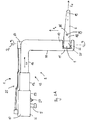
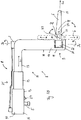
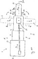
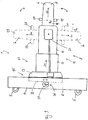
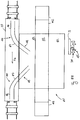
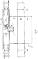
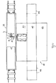
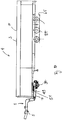
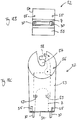
- FIGS. 3A . 4A and 5A are a side view, a top view and a cross section of the coupling device 1 are shown.
- the coupling device 1 has a pin-shaped coupling member 5 for producing a detachable and rotatable connection with a corresponding coupling element 15 of the vehicle 2.
- the vehicle is a semi-trailer, in which the coupling element 15 is configured as a hydraulically raisable and lowerable fifth wheel plate.
- the coupling device 1 also comprises a coupling arm 6, which in a coupling jaw 7 of the loading platform 3, see FIG. 2 , can be imported.
- the coupling device 1 also comprises an intermediate member 8, which is arranged between the coupling member 8 and the coupling arm 6 and connects them together.
- the coupling device 1 also comprises a rotary joint 9, which rotatably connects the coupling arm 6 with the intermediate member 8.
- the rotary joint 9 has a substantially vertically oriented axis of rotation D v , about which the coupling arm 6 is laterally pivotable relative to the intermediate member 8.
- the vertically oriented axis of rotation D v is parallel to the H F vertical axis of the vehicle 2 and parallel to the vertical axis H L of the loading platform.
- the coupling member 5 of the coupling device 1 is arranged in a vehicle-facing front portion 10 of the intermediate member 8.
- the swivel joint 9 is arranged relatively further back in a rear region 11 of the intermediate member 8 facing the loading platform 3 FIG. 1 can be seen particularly well, the intermediate member 8 is configured such that the rear portion 11 of the intermediate member 8 and the pivot 9 are located with the vertical axis of rotation D v behind the vehicle 2 and between the vehicle 2 and the loading platform 3.
- the intermediate member 8 has a vehicle 12 adapted to the dimensions of the vehicle, which is configured in this example L-shaped and at least one, in this case a plurality of substantially horizontally extending sections 13 and a substantially vertically extending portion 14, according to the shape of known gooseneck couplings.
- the horizontally extending sections 13 are telescopically connected to each other in this example and be slidable to extend and shorten the carrier 12 along a horizontal Lekssache L T of the carrier 12, so that in this way a sliding joint 25 of the coupling device 1 is formed.
- the coupling member 8 is arranged in at a front, horizontally extending end portion of the carrier 12 and the pivot 9 on a coupling arm 6 facing rear, vertically extending end portion 17 of the carrier 12 is arranged.
- the coupling arm 6 has a longitudinal axis L K and extends along this longitudinal axis L K of a pivot 9 facing the front end portion 18 of the coupling arm 6 to a pivot 9 remote from the rear end portion 19 of the coupling arm 6 and extends here over a length of between about 0.3 m to about 1 m, for example over a length of about 0.5 m.
- the coupling arm 6 has a maximum width (measured along a transverse axis Q K of the coupling arm 6, see FIG. 4A ) between about 10 cm to about 40 cm, in the present case for example 20 cm, and a maximum thickness (measured along a vertical axis H K of the coupling arm) between 10 cm to about 40 cm, in the present example about 15 cm.
- FIG. 4A how very good in FIG. 4A can be seen, 6 two lateral securing pins 29 are arranged on side surfaces 28 of the front end portion 18 of the coupling arm.
- the loading platform also has this, as well as in Figures 1 and 2 can be seen, at least one wheel axle 34.
- a second hinge element 21 of the rotary member 9 adjoins the intermediate member 8, more precisely to the portion 14 of the carrier or to the rear portion of the intermediate member 8, and is thus connected to the intermediate member 8.
- the second joint element 21 is in this example as a pivot bearing (radial bearing) for the first joint element, or its shaft 22.
- the coupling device 1 has a first drive 23 for the rotary joint 8, via a parallel to the vertical axis of rotation D v extending drive shaft 24 is rotatably connected to the shaft 22 of the first joint member 20, so that by means of the first drive 23 via the rotary shaft 24 of the coupling arm 6 about the vertical axis of rotation D v of the rotary joint 9 can be rotated.
- the first drive 23 may be configured, as may be the case with all other drives of the coupling device 1, for example as a hydraulic transmission or as a mechanical transmission or as an electric transmission.
- the coupling device also includes a drive (not shown) for the sliding joint 25 formed by the telescopic sections 13 of the support 12.
- the shaft 22, as part of the second joint element it would also be possible in principle for the shaft 22, as part of the second joint element, to be connected in a rotationally fixed manner to the intermediate member 8 (strictly speaking, the shaft 22 in this case is a non-rotatable axle of the rotary joint).
- the first joint member 20 would be correspondingly as a pivot bearing (radial bearing) for the second joint member 21 (or its Shaft 22) designed.
- the first drive could be arranged in this case, for example, at the rear end 17 of the carrier 12.
- FIGS. 1 and 4A can be understood, in the lateral pivoting of the coupling arm 6 about the vertical axis of rotation D v an angle between the longitudinal axis L K of the coupling arm 6 and the longitudinal axis L T of the carrier 12 and possibly also the longitudinal axis L F of the vehicle 2 is reduced or enlarged , the latter in particular without simultaneously changing the relative orientation of the intermediate member 8 and the carrier 12 to the vehicle 2.
- the angle between the longitudinal axis L L of the loading platform and the longitudinal axis L F of the vehicle changes accordingly.
- the drive 23 also includes a rear locking device 26, with which the pivot 9 can be locked in a momentary orientation of the coupling arm 6 relative to the intermediate member 8, so as to block rotations of the coupling arm 6 about the vertical axis of rotation D v .
- the coupling device 1 comprises a front locking device 27 for locking the intermediate member 8 in an instantaneous orientation of the intermediate member 8 relative to the vehicle 2, wherein the front locking device is configured, for example, as a hydraulically axially displaceable securing bolt.
- the vehicle 2 has in this example corresponding receptacles (not shown) for front locking device 27.
- the front locking device 26 and the rear locking device 27 are synchronously via a control unit (not shown) or locked in mutual exchange and releasable to lock in the latter case alternately the intermediate member 8 relative to the vehicle 2 and the coupling arm 6 relative to the intermediate member 5 to be able to.
- the coupling arm 6 about the vertical axis of rotation D v , each starting from a center orientation of the coupling arm 6 (shown here by solid lines), in a first direction of rotation by 90 ° in a left orientation (shown with dotted lines) and also rotated in a direction opposite to the first direction of rotation second direction of rotation by 90 ° in a right orientation (also shown by solid lines).
- the coupling arm 6 is aligned straight, so typically along the longitudinal axis L T of the carrier.
- FIGS. 3B . 4B . 5B is a further embodiment of a coupling device 1 shown here proposed type, which differs from the in Fig. 2A . 4A . 5A shown clutch device differs in that the hinge of in FIGS. 3B . 4B . 5B Coupling device 1 shown in addition to the vertical axis of rotation D v has a horizontal axis of rotation D h .
- a flat surface means horizontally in turn parallel to the flat ground.
- the hinge 9 is in the in FIGS. 3B . 4B .
- the third joint element is configured as a (horizontally extending) shaft rotatably connected to the coupling arm 6.
- the fourth joint element 32 comprises a rotary bearing (radial bearing) in which the third joint element 31 is rotatably mounted.
- the coupling device 1 also comprises a further drive 33 for rotations about the horizontal axis of rotation D h .
- the coupling arm 6 of this coupling device 6 is about the horizontal axis of rotation D h , in each case starting from the already defined above center alignment of the coupling arm 6, in a third direction by up to 90 ° and in a direction opposite to the third direction of rotation fourth direction of rotation is rotatable down to 90 °.
- the coupling arm 6 can thus be pivoted upwards or downwards by 90 °, so that the longitudinal axis L K of the coupling arm is oriented vertically.
- the loading platform 3 When turning the coupling arm 6 down the loading platform 3 can be tilted, for example, for unloading or even placed vertically. By turning 90 ° upward, the coupling arm 6 can be folded away, for example, to save space or to improve the maneuverability of the vehicle 2.
- the coupling device 1 on the rear side facing away from the vehicle 2 of the intermediate member 8 have further coupling elements for producing a detachable Connection with a loading platform 3 by means of these further coupling elements.
- FIG. 6 shows in a side view a variant of in FIG. 1 shown system 4, which differs from the in FIG. 1 shown system 4 essentially only differs in that the vehicle 2 is designed as a forklift and the coupling device 1 is adapted thereto accordingly.
- this vehicle 2 is shown with the coupling device 1, but without the loading platform 3, in a view from above, wherein the coupling arm 6 of the coupling device 1 is pivoted laterally.
- FIGS. 8 and 9 is the in FIGS. 6 and 7 shown coupling device 1 shown separately.
- This coupling device differs from that in FIGS. 3A . 4A and 5A shown coupling device 1 substantially only by the configuration of the coupling members 5 and by a further sliding joint 35.
- the coupling members 5 are here for establishing the connection with the in FIGS. 6 and 7 shown vehicle 2, ie with a forklift, are formed.
- the further sliding joint 35 is designed to displace the sections 13 of the carrier in the horizontal direction relative to the front end 16 of the carrier 12.
- the coupling device 1 comprises a suitably arranged further drive 36, for example a driven gear 37 and a gear plate engaging in the gear 38 38 (the teeth of the gear 37 and the gear plate 38 are not shown).
- Coupling device 1 shown can also according to the in FIGS. 3B . 4B and 5B shown coupling device 1 are executed, in which the rotary joint 9 is provided with a horizontal axis of rotation D h and, for example, as in FIGS. 3B . 4B and 5B is designed shown. Accordingly, the coupling device 1 can also be equipped with a further drive 33 for the horizontal axis of rotation D h .
- Coupling device 1 shown is thus on the description of FIGS. 3A . 3B . 4A . 4B . 5A and 5B directed.
- the use of the coupling device 1 proposed here is based on the example of loading a freight wagon 39 configured as a flat wagon with a loading platform 3 via a further loading platform designed as a mobile loading ramp 40.
- the vehicle 1 is, for example, a forklift from the in FIGS. 6 and 7 shown type, via a coupling device 1 of in FIGS. 8 and 9 shown connected to the loading platform 3.
- the loading platform 3 to be loaded is, for example, a roll trailer with a length of about 7 m, the freight wagon having a loading area with a length of about 18 m.
- the loading platform 3 is first pushed onto a loading area 43 of the mobile loading ramp 40 via ramp elements 42 of the mobile loading ramp 40. From the loading area 43 from the loading platform 3 is moved to the freight car 43, see FIG. 11 , wherein when moving the loading platform 3 of the inserted into the coupling jaw 7 of the loading platform 3 coupling arm 6 of the coupling device 1 rotates about the vertical axis of rotation of the rotary joint 9. As a result, the relative orientation of the longitudinal axis L F of the vehicle 2 to the longitudinal axis L L of the loading platform 3 changes. If the loading platform 3 is aligned parallel to the goods wagon, see FIG. 11 , In the example shown, the longitudinal axis L F of the vehicle 2 is perpendicular to the longitudinal axis L L of the loading platform. 3
- the coupling arm 6 is pulled out of the coupling jaw 7 by pressing the further sliding joint 35 of the coupling device 1.
- Figures 13 and 14 clarify that by extending the support 12 by means of the sliding joint 25, the length of the support 12 of the coupling device 1 can be extended so far that the vehicle does not have to drive onto the freight wagon when loading the loading platform 3 on the goods wagon 39, but completely on the back of the mobile loading dock 40 may remain. Again, the coupling arm 6 is pulled out of the coupling jaw 7 by pressing the further sliding joint 35 of the coupling device 1.
- the loading platform 3 to be loaded in addition to at least one roadworthy wheelset (wheel axle) 34 at least one rail-compatible wheelset 45 (wheel axle), said wheelsets are height adjustable relative to each other by means of a hydraulic drive.
- suitable rails 44 are arranged for this rail-suitable wheelset.
- the rails 44 comprise a first section 46 extending parallel to the longitudinal axis L G of the freight wagon 39 and having at least one second section 47 adjoining it and bending in the direction of a side edge of the bed of the freight wagon, this second section continuing to the side edge of the loading area.
- the mobile loading ramp 40 also has rails 48 on its loading surface 43 which run in the direction of a side edge of the loading surface 43 of the loading ramp and continue up to the side edge of the loading surface 43.
- the loading dock 40 has been aligned relative to the freight car 39 so that the loading areas of the freight car and the loading dock are at the same level, connect the rails 48 of the loading dock 40 directly to the rails 44 of the freight car 39 and the loading platform 3 can be pushed along the rails of the loading dock 3 on the rails of the freight car.
- FIG. 15 also shows that the two outer loading surfaces 43 of the mobile loading platform 40 off FIGS. 10A to 14 are supported on support members 48 and also can be folded upwards (see dashed lines in FIG. 15 ) when the mobile loading platform is pulled by a vehicle 1.
- the ramp elements are based on support elements (not shown) and can be folded upwards in the same way.
- the mobile loading platform 40 in turn has a coupling jaw 7.
- FIG. 16 is shown as a further example of a loading platform 3 of the system 4 proposed here, a Rolltrailer having on its front a coupling jaw 7 and two support arms 30 and on its underside two roadworthy axles 34. He is for example loaded with a container 41.
- FIG. 17 a system 4 with a coupling device 1 of the type proposed here is shown, which is connected via a dolly trailer 49 of a type proposed here to a conventional semi-trailer 50 (ie without its own coupling jaw).
- the dolly trailer has on its front a coupling jaw 7 and on its upper side a fifth wheel plate 51 with a receptacle for a connecting pin (kingpin) of the semitrailer 50.
- FIG 18A a system 4 with a coupling device 1 of the type proposed here is shown, which is connected to a conventional semi-trailer 50 via a coupling adapter 52 of a type proposed here.
- the coupling adapter comprises a base part 53 which has on a front side of the base part 53 a coupling jaw 7 for receiving the coupling arm 6 of the coupling device 1.
- a saddle plate 51 is arranged with a receptacle for a connecting pin (not shown) of the semitrailer 50.
- FIG. 18B how very clear in FIG. 18B can be seen, at the front of the base member 53, a plate-shaped, vertically upwardly oriented support 54 is arranged, the plurality of bolts 55 (see Figures 18B and 18C ), which are aligned starting from the carrier 55 to the rear, ie in the direction of the fifth wheel plate 51 of the coupling adapter 52.
- the semi-trailer 50 has on its front side a corresponding number of receptacle (not shown) for the bolt 55.
- the fifth wheel 51 of the clutch adapter 51 has a locking mechanism 56 (elements disposed inside the base 53 and the fifth wheel 51 are shown in dashed lines) with which the kingpin of the semi-trailer 51 locks in an associated seat 57 of the fifth wheel 51 can be.
- the lock mechanism 56 includes at least one movable latch member 58 that can be moved between an open state and a locked state (in FIG Figure 18C indicated by a double arrow), whereby the kingpin of the semitrailer can be locked or released in the receptacle 57.
- the locking mechanism 56 includes movably mounted elements 59 which project into the coupling jaw 7 and by lateral pivoting of the coupling arm 6 within the coupling jaws 7 can be operated.
- the elements 59 are connected to the at least one locking element 58 such that opening of the locking arm 6 is effected by turning the coupling arm 6 to the left and closing the locking element 58 by turning the coupling arm 6 to the right.
- FIG. 19 are two, for example, designed as a forklift vehicles 2, each of which is a coupling device 1 here proposed type, for example, as in FIGS. 6 to 9 shown, and a coupling adapter 52 proposed here type are connected to a designed as a container 41 loading platform 3 and lift them on a freight car 39 and settle on this. Subsequently, the two coupling adapters 52 can be released from the loading platform 3 and removed, for example by means of the vehicles 2 and the coupling devices 1, or else remain on the loading platform 3.
- a coupling device 1 here proposed type for example, as in FIGS. 6 to 9 shown
- a coupling adapter 52 proposed here type are connected to a designed as a container 41 loading platform 3 and lift them on a freight car 39 and settle on this. Subsequently, the two coupling adapters 52 can be released from the loading platform 3 and removed, for example by means of the vehicles 2 and the coupling devices 1, or else remain on the loading platform 3.
- FIG. 20 is a side view of one of the in FIG. 19 shown coupling adapter 52, which is connected to a coupling device 1 of the type proposed here.
- the coupling adapter 52 has on a front side of a base part 53 of the coupling adapter 52 a coupling jaw 7 and on a rear side of the base part 53 coupling elements 60 which are arranged with corresponding coupling elements 61 which are arranged on the front or rear side of the loading platform 61. are detachably connected.
- the coupling elements 60, 61 are configured as twist-lock elements.
- the coupling device 1 shown here has an intermediate member 8, at the top of a designed as a heavy-duty eye coupling member 5 is arranged, with which it is connected via a cable or a chain with a vehicle, such as a crane or a forklift (not shown) ,
- a coupling arm 6 is arranged, which is rotatably connected via a rotary joint 9 with the intermediate member 9 and is inserted into the coupling jaw 7 of the coupling adapter 52.
- a counterweight 62 is arranged for stabilizing the suspended on the heavy-duty coupling device.
- FIG. 21 shows a view from the top of the in FIG. 20 shown coupling adapter 52, which in turn is connected to a coupling device 1 of the type proposed here.
- a coupling device 1 of the type proposed here.
- the at the back of the Base part 53 of the clutch adapter 52 arranged coupling elements 60 which are releasably connected to the corresponding coupling elements 61 of the loading platform 61.
- support arms 30 of the coupling adapter 52 which are arranged on the front side of the base part 53 laterally on the coupling jaw 7 for supporting on corresponding securing pin 29 of the inserted into the coupling jaw coupling arm 6 of the coupling device. 1
- FIG. 22 two vehicles 2 are shown, which are each connected via a coupling device 1 of the type proposed here and a coupling adapter 52 here proposed type with a loading platform 3.
- the left vehicle 1 and the left coupling device 1 may be, for example, the in FIG. 1 shown vehicle 1 or the in FIG. 1 shown coupling device 1 act.
- the right vehicle 1 and the right coupling device 1 may be, for example, the in FIG. 6 shown vehicle 1 or the in FIG. 6 shown coupling device 1 act.
- the two coupling adapters 52 each have a base part 53, which has coupling elements 60 on its upper side, which are designed, for example, as twistlock elements.
- the loading platform 3 is designed as a container 41 (alternatively as a container platform) and has on its underside coupling elements 61, which are also configured in this example as twistlock elements and with the corresponding coupling elements 60 of the coupling adapter 52 are detachably connected.
- the right clutch adapter 52 also has a roadworthy (and / or rail compatible) wheelset 63 on its underside.
- the loading platform 3 can be raised via the coupling devices 1, whose coupling arms 6 are inserted into coupling mouths 7 of the coupling adapter 52. Then support legs 64 can be removed on the underside of the loading platform, pulled or folded.
- the right-hand coupling adapter 52 is lowered and set down with the wheelset 63 on the ground 65. With the left vehicle 2 can then, possibly after a partial lowering of the left coupling device 1, the loading platform 3 moves (pulled or pushed), the loading platform rolls over the wheel 63.
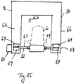
- FIGS. 23 to 25 These are the different views of a further embodiment of the proposed coupling device 1.
- the intermediate member 8 on an L-shaped support 14 with two outer supports 66, which are parallel to each other and vertical sections 14 of the support 12 represent and each at a substantially horizontally extending Start section 13 of the carrier 12.
- the two outer supports 66 are connected to each other by a substantially horizontally extending cross member 67.
- the coupling arm 6 is suspended via its front end piece 18 on the cross member 67 between the two outer supports 66 by means of a suspension 68, which in this example is a non-rotatable connection between the coupling arm 6 and the cross member 67 and forms together with the cross member 67, a first joint element 20 of the rotary joint 9 of the coupling device 1.
- the cross member 67 has the function of a shaft 22 and is connected to a correspondingly designed drive 23.
- a second joint element 21 of the pivot joint 9 is arranged in each case, which are designed as bearing elements for the cross member 67 and the shaft 22.
- the rotary joint 9 thus has a horizontal axis of rotation D h , which passes through the cross member 67 coaxially, wherein the cross member 67 is rotatably mounted in the bearing elements about the horizontal axis of rotation D h of the rotary joint 9.
- the intermediate member 8 of the coupling device 1 has on its rear side in addition to the coupling arm 6 further coupling elements 69, which are arranged for example on the lower and rear end pieces 17 of the outer support 69 and the typical as well as the coupling arm cantilevered over the back of the intermediate member 8 to the rear protrude.
- These coupling elements 69 are for making a releasable connection with corresponding coupling elements 70 of the loading platform, see FIGS. 26 to 28 , designed.
- the coupling elements 69, 70 are, for example, hook elements and corresponding receiving elements which can be brought into releasable engagement with one another.
- the coupling device 1 further comprises a locking mechanism with a drive, by means of which the coupling elements 69 can be opened and closed.
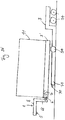
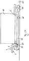
- FIGS. 26 to 28 is a second loading platform 3 'with a coupling jaw 7 shown by means of in FIG. 23 shown coupling device 1 is loaded on a low bed 71 of a first loading platform 3 (the vehicle used for this is not shown).
- the second loading platform 3' by means of the coupling device 1 is unilaterally raised and by means of the wheels 34 'of this loading platform 3' so on the low bed 71 are rolled, that the deep bed 71 is disposed in a space 72 between the left and right wheels 34 'of the second loading platform 3' below the second loading platform 3 ', see FIG.
- the second loading platform 3 ' can be placed on the deep bed 71 and the coupling arm 6 and the coupling jaw 7 of the second loading platform 3' are moved out.
- the first loading platform 3 with the coupling device 1 via the coupling elements 69 and 70 of the coupling device 1 and the loading platform 3 are connected (the coupling elements 69, 70 are in FIG. 26 not shown), after previously the coupling arm 6 of the coupling device 1 has been turned away upwards (see dashed line illustration of the coupling arm 6 in FIG. 27 ).
- the deep bed 71 means of the coupling device 1 and possibly a separate (hydraulic) lifting device of the axles 34 of the first loading platform 3, to be raised so far between the wheels 34 'of the second loading platform 3' and the ground 65 no longer exists and a sufficiently large distance has been established. Subsequently, the first loading platform 3 can be pulled or pushed by means of the coupling device 1.
- the low bed 71 of the first loading platform 3 has a maximum width B max (measured in the direction of the transverse axis of the low bed) that is less than a minimum distance A min between the left and right wheels 34 'of the second loading platform 3' (FIG. measured in the direction of the transverse axis of the second loading platform 3 ').
- a maximum height H max of the deep bed 71 is smaller than a ground clearance BF of the second loading platform 3 '(defined as the smallest distance between the ground 65 and the lowest fixed area of the second loading platform 3' between the left and right wheels of the second loading platform 3 ').
Landscapes
- Engineering & Computer Science (AREA)
- Transportation (AREA)
- Mechanical Engineering (AREA)
- Chemical & Material Sciences (AREA)
- Combustion & Propulsion (AREA)
- Health & Medical Sciences (AREA)
- Public Health (AREA)
- Aviation & Aerospace Engineering (AREA)
- Handcart (AREA)
Claims (15)
- Dispositif de couplage (1) destiné à établir une liaison amovible entre un véhicule (2) et une plateforme de chargement (3) pour des marchandises à transporter lourdes, où le dispositif de couplage (1) comprend un élément de couplage (5) pour relier le dispositif de couplage (1) avec le véhicule (2) et un bras de couplage (6) pour l'insertion du bras de couplage (6) dans une embouchure de couplage de la plateforme de chargement (3), où le dispositif de couplage (1) comprend en outre un élément intermédiaire (8), lequel est disposé entre l'élément de couplage (5) et le bras de couplage (6), où le dispositif de couplage (1) comprend un pivot (9), lequel relie le bras de couplage (6) de manière rotative avec l'élément intermédiaire (8),
où le pivot (9) présente un axe de rotation vertical, autour duquel le bras de couplage (6) peut pivoter latéralement par rapport à l'élément intermédiaire (8),
caractérisé en ce
que le bras de couplage (6) peut pivoter autour de l'axe de rotation vertical, en partant d'une orientation centrale du bras de couplage (6), de 90° dans une première direction de rotation, et de 90° dans une deuxième direction de rotation, opposée à la première direction de rotation. - Dispositif de couplage (1) selon la revendication 1, caractérisé en ce que le bras de couplage (6) s'étend le long d'un axe longitudinal du bras de couplage (6) à partir d'une pièce d'extrémité avant du bras de couplage (6), orientée vers le pivot (9), jusqu'à une pièce d'extrémité arrière du bras de couplage (6), opposée au pivot (9), où un premier élément d'articulation du pivot (9) est limitrophe avec la pièce d'extrémité avant du bras de couplage (6) et est relié avec le bras de couplage (6), et un deuxième élément d'articulation du pivot est limitrophe avec l'élément intermédiaire (8) et est relié avec l'élément intermédiaire (8), où le premier élément d'articulation et le deuxième élément d'articulation du pivot (9) sont rotatifs l'un par rapport à l'autre autour de l'axe de rotation vertical du pivot (9).
- Dispositif de couplage (1) selon l'une des revendications précédentes,
caractérisé en ce le pivot (9) présente un axe de rotation horizontal, autour duquel le bras de couplage (6) peut pivoter vers le haut et vers le bas par rapport à l'élément intermédiaire (8). - Dispositif de couplage (1) selon l'une des revendications précédentes,
caractérisé en ce que le dispositif de couplage (1) comprend en outre un joint à glissière (25), qui est conçu pour déplacer le bras de couplage (6) par rapport à l'élément de couplage (5) le long d'au moins un axe de déplacement du joint à glissière (25). - Dispositif de couplage (1) selon la revendication 4, caractérisé en ce que le dispositif de couplage (1) présente au moins un entraînement pour le joint à glissière.
- Dispositif de couplage (1) selon l'une des revendications précédentes,
caractérisé en ce que le dispositif de couplage (1) présente au moins un entraînement pour le pivot (9). - Dispositif de couplage (1) selon l'une des revendications précédentes,
caractérisé en ce que le dispositif de couplage (1) comprend- un dispositif de butée arrière (26) pour le blocage de mouvements de rotation du pivot (9)
et/ou- un dispositif de butée avant (27) pour le blocage de mouvements de rotation de l'élément intermédiaire (8) par rapport au véhicule (2). - Système (4) destiné au transport de marchandises à transporter lourdes, comprenant au moins un dispositif de couplage (1) selon l'une des revendications précédentes et au moins un véhicule (2), où l'au moins un véhicule (2) présente un élément de couplage, qui est conçu pour l'établissement d'une liaison amovible avec l'élément de couplage (5) du dispositif de couplage (1), où au moins un véhicule (2) de l'au moins un véhicules du système est de préférence un tracteur, un véhicule industriel, un chariot élévateur pour charges lourdes, un chariot élévateur à fourche, un tracteur RORO ou un tracteur portuaire.
- Système (4) selon la revendication 8, caractérisé en ce que le système (4) comprend au moins une plateforme de chargement (3) pour des marchandises à transporter lourdes, où l'au moins une plateforme de chargement (3) comprend une embouchure de couplage pour la réception du bras de couplage (6) de l'au moins un dispositif de couplage (1), où au moins une plateforme de chargement (3) parmi l'au moins une plateforme de chargement (3) du système est de préférence un semi-remorque de conteneurs, un semi-remorque, un châssis pour conteneurs, une remorque à lit plat, une remorque Dolly ou une rampe de chargement mobile.
- Système (4) selon l'une des revendications 8 ou 9, caractérisé en ce que le système (4) comprend au moins un adaptateur d'attelage (52) pour l'établissement d'une liaison amovible entre le bras de couplage (6) du dispositif de couplage (1) et une plateforme de chargement (3) conçue sous la forme d'une semi-remorque, où l'adaptateur d'attelage (52) comprend une partie de base (53), qui présente sur une face avant de la partie de base (53) une embouchure de couplage (7) pour la réception du bras de couplage (6) du dispositif de couplage (1), où, sur une face supérieure de la partie de base (53) est disposée une plaque d'attelage (51) avec un logement (57) pour une broche de connexion du semi-remorque.
- Système (4) selon l'une des revendications 8 à 10, caractérisé en ce qu'au moins l'une des plateformes de chargement (3) présente un train de roues (34) approprié pour les routes ainsi qu'un train de roues (45) approprié pour les rails, où les trains de roues (34, 45) de cette plateforme de chargement (3) sont réglables en hauteur l'un par rapport à l'autre pour l'utilisation des trains de roues (34, 45) en alternance, où le système (4) comprend au moins un wagon à marchandises relié à des rails (39), notamment un wagon plat, où des rails (44) pour les trains de roues (45) appropriés pour les rails de ladite plateforme de chargement (3) sont disposés sur la surface de chargement du wagon à marchandises (39), où les rails (44) présentent une portion (46) s'étendant parallèlement par rapport à l'axe longitudinal du wagon à marchandises (39) et au moins une section (47) faisant suite à ce niveau et se recourbant en direction d'un bord latéral de la surface de chargement.
- Procédé d'utilisation d'un dispositif de couplage (1) selon l'une des revendications 1 à 7 et d'utilisation d'un système (4) selon l'une des revendications 8 à 11, caractérisé en ce qu'une plateforme de chargement (3) est déplacée au moyen du dispositif de couplage (1) et que le bras de couplage (6) est simultanément mis en rotation au moyen du pivot (9) du dispositif de couplage (1).
- Procédé selon la revendication 12, caractérisé en ce que, pendant le mouvement de la plateforme de chargement (3), l'élément intermédiaire (8) du dispositif de couplage (1) est mis en butée sans pouvoir tourner par rapport au véhicule (2) pour le blocage de mouvements de rotation de l'élément intermédiaire (8) par rapport au véhicule (1).
- Procédé selon l'une des revendications 12 ou 13, caractérisé en ce qu'avant l'insertion du bras de couplage (6) dans l'embouchure de couplage de la plateforme de chargement (3) et/ou après le retrait du bras de couplage (6) hors de l'embouchure de couplage de la plateforme de chargement (3), le bras de couplage (6) est mis en rotation au moyen du pivot (9).
- Procédé selon l'une des revendications 12 à 14, caractérisé en ce que le bras de couplage (6) est déplacé au moyen d'un joint à glissières de l'élément intermédiaire (8) le long d'un axe longitudinal du bras de couplage (6) et le bras de couplage (6) est inséré par ce déplacement dans l'embouchure de couplage de la plateforme de chargement (3) ou est retiré de l'embouchure de couplage de la plateforme de chargement (3).
Priority Applications (1)
| Application Number | Priority Date | Filing Date | Title |
|---|---|---|---|
| EP14186446.2A EP3000696B1 (fr) | 2014-09-25 | 2014-09-25 | Dispositif d'accouplement, système doté d'un tel dispositif d'accouplement et utilisation d'un tel dispositif d'accouplement |
Applications Claiming Priority (1)
| Application Number | Priority Date | Filing Date | Title |
|---|---|---|---|
| EP14186446.2A EP3000696B1 (fr) | 2014-09-25 | 2014-09-25 | Dispositif d'accouplement, système doté d'un tel dispositif d'accouplement et utilisation d'un tel dispositif d'accouplement |
Publications (2)
| Publication Number | Publication Date |
|---|---|
| EP3000696A1 EP3000696A1 (fr) | 2016-03-30 |
| EP3000696B1 true EP3000696B1 (fr) | 2018-04-11 |
Family
ID=51619025
Family Applications (1)
| Application Number | Title | Priority Date | Filing Date |
|---|---|---|---|
| EP14186446.2A Not-in-force EP3000696B1 (fr) | 2014-09-25 | 2014-09-25 | Dispositif d'accouplement, système doté d'un tel dispositif d'accouplement et utilisation d'un tel dispositif d'accouplement |
Country Status (1)
| Country | Link |
|---|---|
| EP (1) | EP3000696B1 (fr) |
Families Citing this family (4)
| Publication number | Priority date | Publication date | Assignee | Title |
|---|---|---|---|---|
| CN108974157B (zh) * | 2017-06-05 | 2024-06-18 | 扬州市伏尔坎机械制造有限公司 | 一种具有升降功能的运输半挂车 |
| DE102019118836B4 (de) * | 2019-07-11 | 2023-11-30 | Saf-Holland Gmbh | Adapteranordnung für eine Sattelzuganordnung |
| US12005825B2 (en) | 2020-11-10 | 2024-06-11 | David William PRESBY | Loading/unloading device for a delivery vehicle |
| US11364834B2 (en) * | 2020-11-10 | 2022-06-21 | David William PRESBY | Loading/unloading device for a delivery vehicle |
Family Cites Families (9)
| Publication number | Priority date | Publication date | Assignee | Title |
|---|---|---|---|---|
| DE2112113A1 (de) | 1971-03-13 | 1972-09-28 | Fiala Kg Martin | Vorrichtung zum Aufsatteln eines fahrbaren Ladegestelles |
| SE406884B (sv) * | 1978-06-12 | 1979-03-05 | Infis Ab | Anordning vid svanhals for rolltrailer |
| DE3116932A1 (de) | 1981-04-29 | 1982-11-18 | LESA-Konstruktionen Sauer KG, 5190 Stolberg | Kupplungsvorrichtung |
| US4377296A (en) * | 1981-06-22 | 1983-03-22 | Ulshafer Jr Carl | Hitching apparatus |
| DK2327655T3 (da) * | 2009-11-30 | 2012-09-24 | Siemens Ag | Indretning til transport af vindmøllekomponenter |
| EP2357122A1 (fr) | 2010-02-17 | 2011-08-17 | F.W. Grundt Logistik + Spedition GmbH & Co. KG | Adaptateur de couplage destiné à connecter des systèmes de transport pour charges lourdes |
| WO2011151847A1 (fr) * | 2010-06-04 | 2011-12-08 | T.C.M S.R.L. | Dispositif de levage et de remorquage de véhicules, en particulier de véhicules à moteur militaires lourds |
| EP2594430B1 (fr) * | 2011-11-18 | 2016-05-25 | Blue Water Shipping A/S | Véhicule de transport d'une pale |
| EP2660102B1 (fr) * | 2012-05-03 | 2014-11-19 | Omars S.r.l. | Équipement pour récupérer des véhicules en panne et système muni d'un tel équipement |
-
2014
- 2014-09-25 EP EP14186446.2A patent/EP3000696B1/fr not_active Not-in-force
Non-Patent Citations (1)
| Title |
|---|
| None * |
Also Published As
| Publication number | Publication date |
|---|---|
| EP3000696A1 (fr) | 2016-03-30 |
Similar Documents
| Publication | Publication Date | Title |
|---|---|---|
| EP2079607B1 (fr) | Chariot de transport relié au sol, en particulier pour le transport de conteneurs | |
| EP3268257B1 (fr) | Dispositif de transport levable | |
| DE2451165A1 (de) | Transportfahrzeug zur befoerderung von containern | |
| DE69623989T2 (de) | Eisenbahngüterwagen | |
| EP3000696B1 (fr) | Dispositif d'accouplement, système doté d'un tel dispositif d'accouplement et utilisation d'un tel dispositif d'accouplement | |
| DE102007039778A1 (de) | Flurgebundenes Transportfahrzeug, insbesondere für den Transport von Containern | |
| DE2952984T1 (de) | Hauling vehicle | |
| DE1605068C3 (de) | Zugmaschine für die Verwendung auf Schiene und Straße | |
| EP0064053A1 (fr) | Wagon a plateforme surbaissee pour le ferroutage de vehicules automobiles et de conteneurs geants | |
| DE69730326T2 (de) | Portalhubwagen | |
| DE4328635C1 (de) | Ladegeschirr mit beweglichen Kupplungsorganen, insbesondere verdrehbaren Verriegelungsbolzen | |
| DE3822542A1 (de) | Ladeanhaenger | |
| DE2325074A1 (de) | Schnabelwagen | |
| EP4122791B1 (fr) | Système d'approvisionnement destiné à l'approvisionnement en produits en vrac et béton prêt à l'emploi | |
| DE102006014214A1 (de) | Einrichtung zum Auf- und Abladen einer Befülleinrichtung quer zu deren Transportrichtung | |
| DE69511673T2 (de) | Auf Eisenbahnwagen transportierbare Rampen zum Verladen von Standard-Sattelaufliegern auf, aus besonderen Einheiten zusammengestellte, Züge | |
| EP3473580A1 (fr) | Dispositif d'embarquement | |
| DE102005035379B4 (de) | Mehrgliedriger Anhänger | |
| EP1736391B1 (fr) | Dispositif et procédé pour le chargement des remorques sur wagons de chemin de fer | |
| AT523849B1 (de) | Anhänger für ein Kraftfahrzeug | |
| DE4024608C2 (de) | Lastwagen mit einer hydraulischen Abstützvorrichtung | |
| EP2357122A1 (fr) | Adaptateur de couplage destiné à connecter des systèmes de transport pour charges lourdes | |
| EP1688300B1 (fr) | Dispositif pour charger et décharger une plate-forme | |
| DE3211671A1 (de) | Hebebuehne zum anbau an ein strassentransportfahrzeug und mit einer derartigen hebebuehne ausgeruestetes strassentransportfahrzeug | |
| DE20004251U1 (de) | Transportvorrichtung zum Befördern oder Tragen von Lasten sowie Schlitten |
Legal Events
| Date | Code | Title | Description |
|---|---|---|---|
| PUAI | Public reference made under article 153(3) epc to a published international application that has entered the european phase |
Free format text: ORIGINAL CODE: 0009012 |
|
| AK | Designated contracting states |
Kind code of ref document: A1 Designated state(s): AL AT BE BG CH CY CZ DE DK EE ES FI FR GB GR HR HU IE IS IT LI LT LU LV MC MK MT NL NO PL PT RO RS SE SI SK SM TR |
|
| AX | Request for extension of the european patent |
Extension state: BA ME |
|
| 17P | Request for examination filed |
Effective date: 20160921 |
|
| RBV | Designated contracting states (corrected) |
Designated state(s): AL AT BE BG CH CY CZ DE DK EE ES FI FR GB GR HR HU IE IS IT LI LT LU LV MC MK MT NL NO PL PT RO RS SE SI SK SM TR |
|
| RIC1 | Information provided on ipc code assigned before grant |
Ipc: B60P 3/41 20060101ALI20170906BHEP Ipc: B62D 53/08 20060101ALI20170906BHEP Ipc: B62D 53/06 20060101AFI20170906BHEP Ipc: B60P 3/11 20060101ALI20170906BHEP |
|
| GRAP | Despatch of communication of intention to grant a patent |
Free format text: ORIGINAL CODE: EPIDOSNIGR1 |
|
| INTG | Intention to grant announced |
Effective date: 20171019 |
|
| GRAS | Grant fee paid |
Free format text: ORIGINAL CODE: EPIDOSNIGR3 |
|
| GRAA | (expected) grant |
Free format text: ORIGINAL CODE: 0009210 |
|
| AK | Designated contracting states |
Kind code of ref document: B1 Designated state(s): AL AT BE BG CH CY CZ DE DK EE ES FI FR GB GR HR HU IE IS IT LI LT LU LV MC MK MT NL NO PL PT RO RS SE SI SK SM TR |
|
| REG | Reference to a national code |
Ref country code: GB Ref legal event code: FG4D Free format text: NOT ENGLISH |
|
| REG | Reference to a national code |
Ref country code: CH Ref legal event code: EP |
|
| REG | Reference to a national code |
Ref country code: AT Ref legal event code: REF Ref document number: 987722 Country of ref document: AT Kind code of ref document: T Effective date: 20180415 |
|
| REG | Reference to a national code |
Ref country code: IE Ref legal event code: FG4D Free format text: LANGUAGE OF EP DOCUMENT: GERMAN |
|
| REG | Reference to a national code |
Ref country code: DE Ref legal event code: R096 Ref document number: 502014007912 Country of ref document: DE |
|
| REG | Reference to a national code |
Ref country code: NL Ref legal event code: MP Effective date: 20180411 |
|
| REG | Reference to a national code |
Ref country code: LT Ref legal event code: MG4D |
|
| REG | Reference to a national code |
Ref country code: FR Ref legal event code: PLFP Year of fee payment: 5 |
|
| PG25 | Lapsed in a contracting state [announced via postgrant information from national office to epo] |
Ref country code: NL Free format text: LAPSE BECAUSE OF FAILURE TO SUBMIT A TRANSLATION OF THE DESCRIPTION OR TO PAY THE FEE WITHIN THE PRESCRIBED TIME-LIMIT Effective date: 20180411 |
|
| PG25 | Lapsed in a contracting state [announced via postgrant information from national office to epo] |
Ref country code: AL Free format text: LAPSE BECAUSE OF FAILURE TO SUBMIT A TRANSLATION OF THE DESCRIPTION OR TO PAY THE FEE WITHIN THE PRESCRIBED TIME-LIMIT Effective date: 20180411 Ref country code: ES Free format text: LAPSE BECAUSE OF FAILURE TO SUBMIT A TRANSLATION OF THE DESCRIPTION OR TO PAY THE FEE WITHIN THE PRESCRIBED TIME-LIMIT Effective date: 20180411 Ref country code: BG Free format text: LAPSE BECAUSE OF FAILURE TO SUBMIT A TRANSLATION OF THE DESCRIPTION OR TO PAY THE FEE WITHIN THE PRESCRIBED TIME-LIMIT Effective date: 20180711 Ref country code: FI Free format text: LAPSE BECAUSE OF FAILURE TO SUBMIT A TRANSLATION OF THE DESCRIPTION OR TO PAY THE FEE WITHIN THE PRESCRIBED TIME-LIMIT Effective date: 20180411 Ref country code: LT Free format text: LAPSE BECAUSE OF FAILURE TO SUBMIT A TRANSLATION OF THE DESCRIPTION OR TO PAY THE FEE WITHIN THE PRESCRIBED TIME-LIMIT Effective date: 20180411 Ref country code: SE Free format text: LAPSE BECAUSE OF FAILURE TO SUBMIT A TRANSLATION OF THE DESCRIPTION OR TO PAY THE FEE WITHIN THE PRESCRIBED TIME-LIMIT Effective date: 20180411 Ref country code: PL Free format text: LAPSE BECAUSE OF FAILURE TO SUBMIT A TRANSLATION OF THE DESCRIPTION OR TO PAY THE FEE WITHIN THE PRESCRIBED TIME-LIMIT Effective date: 20180411 Ref country code: NO Free format text: LAPSE BECAUSE OF FAILURE TO SUBMIT A TRANSLATION OF THE DESCRIPTION OR TO PAY THE FEE WITHIN THE PRESCRIBED TIME-LIMIT Effective date: 20180711 |
|
| PG25 | Lapsed in a contracting state [announced via postgrant information from national office to epo] |
Ref country code: GR Free format text: LAPSE BECAUSE OF FAILURE TO SUBMIT A TRANSLATION OF THE DESCRIPTION OR TO PAY THE FEE WITHIN THE PRESCRIBED TIME-LIMIT Effective date: 20180712 Ref country code: RS Free format text: LAPSE BECAUSE OF FAILURE TO SUBMIT A TRANSLATION OF THE DESCRIPTION OR TO PAY THE FEE WITHIN THE PRESCRIBED TIME-LIMIT Effective date: 20180411 Ref country code: HR Free format text: LAPSE BECAUSE OF FAILURE TO SUBMIT A TRANSLATION OF THE DESCRIPTION OR TO PAY THE FEE WITHIN THE PRESCRIBED TIME-LIMIT Effective date: 20180411 Ref country code: LV Free format text: LAPSE BECAUSE OF FAILURE TO SUBMIT A TRANSLATION OF THE DESCRIPTION OR TO PAY THE FEE WITHIN THE PRESCRIBED TIME-LIMIT Effective date: 20180411 |
|
| PG25 | Lapsed in a contracting state [announced via postgrant information from national office to epo] |
Ref country code: PT Free format text: LAPSE BECAUSE OF FAILURE TO SUBMIT A TRANSLATION OF THE DESCRIPTION OR TO PAY THE FEE WITHIN THE PRESCRIBED TIME-LIMIT Effective date: 20180813 |
|
| REG | Reference to a national code |
Ref country code: DE Ref legal event code: R097 Ref document number: 502014007912 Country of ref document: DE |
|
| PG25 | Lapsed in a contracting state [announced via postgrant information from national office to epo] |
Ref country code: CZ Free format text: LAPSE BECAUSE OF FAILURE TO SUBMIT A TRANSLATION OF THE DESCRIPTION OR TO PAY THE FEE WITHIN THE PRESCRIBED TIME-LIMIT Effective date: 20180411 Ref country code: SK Free format text: LAPSE BECAUSE OF FAILURE TO SUBMIT A TRANSLATION OF THE DESCRIPTION OR TO PAY THE FEE WITHIN THE PRESCRIBED TIME-LIMIT Effective date: 20180411 Ref country code: RO Free format text: LAPSE BECAUSE OF FAILURE TO SUBMIT A TRANSLATION OF THE DESCRIPTION OR TO PAY THE FEE WITHIN THE PRESCRIBED TIME-LIMIT Effective date: 20180411 Ref country code: DK Free format text: LAPSE BECAUSE OF FAILURE TO SUBMIT A TRANSLATION OF THE DESCRIPTION OR TO PAY THE FEE WITHIN THE PRESCRIBED TIME-LIMIT Effective date: 20180411 Ref country code: EE Free format text: LAPSE BECAUSE OF FAILURE TO SUBMIT A TRANSLATION OF THE DESCRIPTION OR TO PAY THE FEE WITHIN THE PRESCRIBED TIME-LIMIT Effective date: 20180411 |
|
| PLBE | No opposition filed within time limit |
Free format text: ORIGINAL CODE: 0009261 |
|
| STAA | Information on the status of an ep patent application or granted ep patent |
Free format text: STATUS: NO OPPOSITION FILED WITHIN TIME LIMIT |
|
| PG25 | Lapsed in a contracting state [announced via postgrant information from national office to epo] |
Ref country code: IT Free format text: LAPSE BECAUSE OF FAILURE TO SUBMIT A TRANSLATION OF THE DESCRIPTION OR TO PAY THE FEE WITHIN THE PRESCRIBED TIME-LIMIT Effective date: 20180411 Ref country code: SM Free format text: LAPSE BECAUSE OF FAILURE TO SUBMIT A TRANSLATION OF THE DESCRIPTION OR TO PAY THE FEE WITHIN THE PRESCRIBED TIME-LIMIT Effective date: 20180411 |
|
| 26N | No opposition filed |
Effective date: 20190114 |
|
| PG25 | Lapsed in a contracting state [announced via postgrant information from national office to epo] |
Ref country code: MC Free format text: LAPSE BECAUSE OF FAILURE TO SUBMIT A TRANSLATION OF THE DESCRIPTION OR TO PAY THE FEE WITHIN THE PRESCRIBED TIME-LIMIT Effective date: 20180411 |
|
| REG | Reference to a national code |
Ref country code: CH Ref legal event code: PL |
|
| PG25 | Lapsed in a contracting state [announced via postgrant information from national office to epo] |
Ref country code: SI Free format text: LAPSE BECAUSE OF FAILURE TO SUBMIT A TRANSLATION OF THE DESCRIPTION OR TO PAY THE FEE WITHIN THE PRESCRIBED TIME-LIMIT Effective date: 20180411 |
|
| REG | Reference to a national code |
Ref country code: BE Ref legal event code: MM Effective date: 20180930 |
|
| REG | Reference to a national code |
Ref country code: IE Ref legal event code: MM4A |
|
| PG25 | Lapsed in a contracting state [announced via postgrant information from national office to epo] |
Ref country code: LU Free format text: LAPSE BECAUSE OF NON-PAYMENT OF DUE FEES Effective date: 20180925 |
|
| PG25 | Lapsed in a contracting state [announced via postgrant information from national office to epo] |
Ref country code: IE Free format text: LAPSE BECAUSE OF NON-PAYMENT OF DUE FEES Effective date: 20180925 |
|
| PG25 | Lapsed in a contracting state [announced via postgrant information from national office to epo] |
Ref country code: BE Free format text: LAPSE BECAUSE OF NON-PAYMENT OF DUE FEES Effective date: 20180930 Ref country code: CH Free format text: LAPSE BECAUSE OF NON-PAYMENT OF DUE FEES Effective date: 20180930 Ref country code: LI Free format text: LAPSE BECAUSE OF NON-PAYMENT OF DUE FEES Effective date: 20180930 |
|
| PGFP | Annual fee paid to national office [announced via postgrant information from national office to epo] |
Ref country code: DE Payment date: 20190905 Year of fee payment: 6 Ref country code: FR Payment date: 20190927 Year of fee payment: 6 |
|
| PGFP | Annual fee paid to national office [announced via postgrant information from national office to epo] |
Ref country code: GB Payment date: 20190920 Year of fee payment: 6 |
|
| PG25 | Lapsed in a contracting state [announced via postgrant information from national office to epo] |
Ref country code: MT Free format text: LAPSE BECAUSE OF FAILURE TO SUBMIT A TRANSLATION OF THE DESCRIPTION OR TO PAY THE FEE WITHIN THE PRESCRIBED TIME-LIMIT Effective date: 20180411 |
|
| PG25 | Lapsed in a contracting state [announced via postgrant information from national office to epo] |
Ref country code: TR Free format text: LAPSE BECAUSE OF FAILURE TO SUBMIT A TRANSLATION OF THE DESCRIPTION OR TO PAY THE FEE WITHIN THE PRESCRIBED TIME-LIMIT Effective date: 20180411 |
|
| PG25 | Lapsed in a contracting state [announced via postgrant information from national office to epo] |
Ref country code: HU Free format text: LAPSE BECAUSE OF FAILURE TO SUBMIT A TRANSLATION OF THE DESCRIPTION OR TO PAY THE FEE WITHIN THE PRESCRIBED TIME-LIMIT; INVALID AB INITIO Effective date: 20140925 Ref country code: CY Free format text: LAPSE BECAUSE OF FAILURE TO SUBMIT A TRANSLATION OF THE DESCRIPTION OR TO PAY THE FEE WITHIN THE PRESCRIBED TIME-LIMIT Effective date: 20180411 Ref country code: MK Free format text: LAPSE BECAUSE OF NON-PAYMENT OF DUE FEES Effective date: 20180411 |
|
| PG25 | Lapsed in a contracting state [announced via postgrant information from national office to epo] |
Ref country code: IS Free format text: LAPSE BECAUSE OF FAILURE TO SUBMIT A TRANSLATION OF THE DESCRIPTION OR TO PAY THE FEE WITHIN THE PRESCRIBED TIME-LIMIT Effective date: 20180811 |
|
| REG | Reference to a national code |
Ref country code: AT Ref legal event code: MM01 Ref document number: 987722 Country of ref document: AT Kind code of ref document: T Effective date: 20190925 |
|
| PG25 | Lapsed in a contracting state [announced via postgrant information from national office to epo] |
Ref country code: AT Free format text: LAPSE BECAUSE OF NON-PAYMENT OF DUE FEES Effective date: 20190925 |
|
| REG | Reference to a national code |
Ref country code: DE Ref legal event code: R119 Ref document number: 502014007912 Country of ref document: DE |
|
| GBPC | Gb: european patent ceased through non-payment of renewal fee |
Effective date: 20200925 |
|
| PG25 | Lapsed in a contracting state [announced via postgrant information from national office to epo] |
Ref country code: FR Free format text: LAPSE BECAUSE OF NON-PAYMENT OF DUE FEES Effective date: 20200930 Ref country code: DE Free format text: LAPSE BECAUSE OF NON-PAYMENT OF DUE FEES Effective date: 20210401 |
|
| PG25 | Lapsed in a contracting state [announced via postgrant information from national office to epo] |
Ref country code: GB Free format text: LAPSE BECAUSE OF NON-PAYMENT OF DUE FEES Effective date: 20200925 |