EP3000977B1 - Schaufel einer turbine mit wasserabweisendem beschichtetem schaufelblatt - Google Patents
Schaufel einer turbine mit wasserabweisendem beschichtetem schaufelblatt Download PDFInfo
- Publication number
- EP3000977B1 EP3000977B1 EP15184244.0A EP15184244A EP3000977B1 EP 3000977 B1 EP3000977 B1 EP 3000977B1 EP 15184244 A EP15184244 A EP 15184244A EP 3000977 B1 EP3000977 B1 EP 3000977B1
- Authority
- EP
- European Patent Office
- Prior art keywords
- blade
- coating
- silicon
- water
- process according
- Prior art date
- Legal status (The legal status is an assumption and is not a legal conclusion. Google has not performed a legal analysis and makes no representation as to the accuracy of the status listed.)
- Not-in-force
Links
- 230000002209 hydrophobic effect Effects 0.000 title description 4
- 238000000576 coating method Methods 0.000 claims description 37
- 239000011248 coating agent Substances 0.000 claims description 36
- XLYOFNOQVPJJNP-UHFFFAOYSA-N water Substances O XLYOFNOQVPJJNP-UHFFFAOYSA-N 0.000 claims description 34
- 238000000034 method Methods 0.000 claims description 20
- 239000002243 precursor Substances 0.000 claims description 18
- 230000008569 process Effects 0.000 claims description 12
- 238000005121 nitriding Methods 0.000 claims description 6
- UQEAIHBTYFGYIE-UHFFFAOYSA-N hexamethyldisiloxane Chemical compound C[Si](C)(C)O[Si](C)(C)C UQEAIHBTYFGYIE-UHFFFAOYSA-N 0.000 claims description 5
- 230000015572 biosynthetic process Effects 0.000 claims description 4
- 238000004132 cross linking Methods 0.000 claims description 2
- KPUWHANPEXNPJT-UHFFFAOYSA-N disiloxane Chemical class [SiH3]O[SiH3] KPUWHANPEXNPJT-UHFFFAOYSA-N 0.000 claims description 2
- 239000010410 layer Substances 0.000 description 20
- 238000005260 corrosion Methods 0.000 description 19
- 230000007797 corrosion Effects 0.000 description 13
- 210000002381 plasma Anatomy 0.000 description 12
- 229920000642 polymer Polymers 0.000 description 10
- 238000004519 manufacturing process Methods 0.000 description 6
- 238000002485 combustion reaction Methods 0.000 description 5
- 229920002493 poly(chlorotrifluoroethylene) Polymers 0.000 description 5
- 239000005023 polychlorotrifluoroethylene (PCTFE) polymer Substances 0.000 description 5
- 229920001343 polytetrafluoroethylene Polymers 0.000 description 5
- 239000004810 polytetrafluoroethylene Substances 0.000 description 5
- 229910000831 Steel Inorganic materials 0.000 description 4
- 230000003628 erosive effect Effects 0.000 description 4
- -1 polytetrafluoroethylene Polymers 0.000 description 4
- 239000010959 steel Substances 0.000 description 4
- 239000000126 substance Substances 0.000 description 4
- 229910003481 amorphous carbon Inorganic materials 0.000 description 3
- 230000008901 benefit Effects 0.000 description 3
- 239000000919 ceramic Substances 0.000 description 3
- 238000000354 decomposition reaction Methods 0.000 description 3
- 238000009499 grossing Methods 0.000 description 3
- 229930195733 hydrocarbon Natural products 0.000 description 3
- 150000002430 hydrocarbons Chemical class 0.000 description 3
- 230000003301 hydrolyzing effect Effects 0.000 description 3
- 229910052751 metal Inorganic materials 0.000 description 3
- 239000002184 metal Substances 0.000 description 3
- 238000005498 polishing Methods 0.000 description 3
- 229920001721 polyimide Polymers 0.000 description 3
- 229920000098 polyolefin Polymers 0.000 description 3
- 239000004215 Carbon black (E152) Substances 0.000 description 2
- VYZAMTAEIAYCRO-UHFFFAOYSA-N Chromium Chemical compound [Cr] VYZAMTAEIAYCRO-UHFFFAOYSA-N 0.000 description 2
- 239000004696 Poly ether ether ketone Substances 0.000 description 2
- 239000004642 Polyimide Substances 0.000 description 2
- 230000035508 accumulation Effects 0.000 description 2
- 238000009825 accumulation Methods 0.000 description 2
- 230000004888 barrier function Effects 0.000 description 2
- JUPQTSLXMOCDHR-UHFFFAOYSA-N benzene-1,4-diol;bis(4-fluorophenyl)methanone Chemical compound OC1=CC=C(O)C=C1.C1=CC(F)=CC=C1C(=O)C1=CC=C(F)C=C1 JUPQTSLXMOCDHR-UHFFFAOYSA-N 0.000 description 2
- 229910052804 chromium Inorganic materials 0.000 description 2
- 239000011651 chromium Substances 0.000 description 2
- 230000000694 effects Effects 0.000 description 2
- 238000009713 electroplating Methods 0.000 description 2
- 229920002313 fluoropolymer Polymers 0.000 description 2
- 239000000295 fuel oil Substances 0.000 description 2
- 230000002401 inhibitory effect Effects 0.000 description 2
- 229910052816 inorganic phosphate Inorganic materials 0.000 description 2
- 238000007733 ion plating Methods 0.000 description 2
- 239000007788 liquid Substances 0.000 description 2
- 239000000463 material Substances 0.000 description 2
- 238000010422 painting Methods 0.000 description 2
- 229920006393 polyether sulfone Polymers 0.000 description 2
- 229920002530 polyetherether ketone Polymers 0.000 description 2
- 230000002829 reductive effect Effects 0.000 description 2
- 239000002356 single layer Substances 0.000 description 2
- 239000007787 solid Substances 0.000 description 2
- 230000003068 static effect Effects 0.000 description 2
- BPQQTUXANYXVAA-UHFFFAOYSA-N Orthosilicate Chemical compound [O-][Si]([O-])([O-])[O-] BPQQTUXANYXVAA-UHFFFAOYSA-N 0.000 description 1
- 239000004698 Polyethylene Substances 0.000 description 1
- 239000004743 Polypropylene Substances 0.000 description 1
- 239000000853 adhesive Substances 0.000 description 1
- 230000001070 adhesive effect Effects 0.000 description 1
- 125000000217 alkyl group Chemical group 0.000 description 1
- 230000000181 anti-adherent effect Effects 0.000 description 1
- 125000003118 aryl group Chemical group 0.000 description 1
- 125000001797 benzyl group Chemical group [H]C1=C([H])C([H])=C(C([H])=C1[H])C([H])([H])* 0.000 description 1
- 239000011230 binding agent Substances 0.000 description 1
- 238000005266 casting Methods 0.000 description 1
- 238000005524 ceramic coating Methods 0.000 description 1
- 229910010293 ceramic material Inorganic materials 0.000 description 1
- 238000010276 construction Methods 0.000 description 1
- 230000036461 convulsion Effects 0.000 description 1
- 230000001419 dependent effect Effects 0.000 description 1
- 238000005470 impregnation Methods 0.000 description 1
- 229910052909 inorganic silicate Inorganic materials 0.000 description 1
- 238000005304 joining Methods 0.000 description 1
- 239000007791 liquid phase Substances 0.000 description 1
- 238000012423 maintenance Methods 0.000 description 1
- 229920000620 organic polymer Polymers 0.000 description 1
- 239000003973 paint Substances 0.000 description 1
- 238000002161 passivation Methods 0.000 description 1
- 238000005240 physical vapour deposition Methods 0.000 description 1
- 229920001643 poly(ether ketone) Polymers 0.000 description 1
- 229920002492 poly(sulfone) Polymers 0.000 description 1
- 229920000573 polyethylene Polymers 0.000 description 1
- 229920001155 polypropylene Polymers 0.000 description 1
- 239000000843 powder Substances 0.000 description 1
- 230000009467 reduction Effects 0.000 description 1
- 239000005871 repellent Substances 0.000 description 1
- 230000000717 retained effect Effects 0.000 description 1
- 239000004576 sand Substances 0.000 description 1
- 239000000565 sealant Substances 0.000 description 1
- 239000002904 solvent Substances 0.000 description 1
- 238000005507 spraying Methods 0.000 description 1
- 239000007858 starting material Substances 0.000 description 1
- 230000003746 surface roughness Effects 0.000 description 1
- 230000007704 transition Effects 0.000 description 1
- 230000005514 two-phase flow Effects 0.000 description 1
- 239000012808 vapor phase Substances 0.000 description 1
- 238000003466 welding Methods 0.000 description 1
Images
Classifications
-
- F—MECHANICAL ENGINEERING; LIGHTING; HEATING; WEAPONS; BLASTING
- F01—MACHINES OR ENGINES IN GENERAL; ENGINE PLANTS IN GENERAL; STEAM ENGINES
- F01D—NON-POSITIVE DISPLACEMENT MACHINES OR ENGINES, e.g. STEAM TURBINES
- F01D5/00—Blades; Blade-carrying members; Heating, heat-insulating, cooling or antivibration means on the blades or the members
- F01D5/12—Blades
- F01D5/28—Selecting particular materials; Particular measures relating thereto; Measures against erosion or corrosion
- F01D5/288—Protective coatings for blades
-
- F—MECHANICAL ENGINEERING; LIGHTING; HEATING; WEAPONS; BLASTING
- F05—INDEXING SCHEMES RELATING TO ENGINES OR PUMPS IN VARIOUS SUBCLASSES OF CLASSES F01-F04
- F05D—INDEXING SCHEME FOR ASPECTS RELATING TO NON-POSITIVE-DISPLACEMENT MACHINES OR ENGINES, GAS-TURBINES OR JET-PROPULSION PLANTS
- F05D2300/00—Materials; Properties thereof
- F05D2300/50—Intrinsic material properties or characteristics
- F05D2300/512—Hydrophobic, i.e. being or having non-wettable properties
Definitions
- the invention relates to a method for manufacturing a blade.
- the invention is particularly applicable to guide vanes of a steam turbine.
- the water plumes that form on the trailing edges of the guide vanes are carried away by the flow in the form of larger water droplets, so-called secondary droplets with diameters between 50 and 400 micrometers. Due to their size and mass and the associated inertia, these droplets can only follow the flow with great difficulty and hit the leading edges of the rotating blades at a high relative speed.
- the locally very high energy input leads to the formation of cracks on the rotor blade surface and continuous drop impact causes material to be removed from the leading edges of low-pressure blades.
- the consequences of droplet impact erosion and the damage to the rotor blades caused by it are decrease the efficiency of the steam turbine and increased maintenance costs.
- DE 696 24 971 T2 discloses a coating for preventing fouling in turbomachinery having a metal surface comprising: a first hardened layer of an adhesive ceramic material with inorganic phosphate as a sacrificial anode in contact with the surface, a second hardened layer in contact with the first layer and a binder with inorganic phosphate or silicate and which is non-conductive and does not serve as a sacrificial anode, and a cured top layer with a heat-stable organic polymer sealant.
- DE 196 07 979 A1 discloses an exhaust tract of a combustion device that can be used in particular for the combustion of heavy oil.
- This exhaust tract is intended to solve the problem of reducing the accumulation of layers of dirt in the exhaust tract of a combustion device that can be used in particular for the combustion of heavy oil and on the components arranged in the exhaust tract to utilize the exhaust gas energy of the combustion device.
- an anti-adhesive coating is arranged on the surface of the at least one component arranged to utilize the exhaust gas energy in the exhaust gas tract or at least one of these components and / or on the surface of the exhaust gas tract itself.
- DE 37 24 626 A1 discloses an airfoil provided with a coating for steam turbines, which is characterized by the actual airfoil and a single-layer coating made of hard, wear-resistant ceramic or a multilayered coating consisting of a sub-layer made of active metal such as Cr and Ti and a top layer made of ceramic, the ceramic coating by ion plating is formed.
- a procedure according to DE 37 24 626 A1 is used to coat a blade for steam turbines, excellent by surface treating the blade surface until the surface roughness is reduced to Rmax 1-2 S and by forming a single-layer or multi-layer coating of ceramic by ion plating.
- WO 98/18977 discloses a coating for components, the boundary surfaces of each component being roughened and a coating of non-wettable amorphous carbon applied to it at least in certain areas. The aim is to create a coating with which the formation of liquid films on the boundary surfaces of components and the formation of solid deposits can be avoided. A method for producing a coating is also disclosed, the boundary surfaces of each component being roughened and at least one coating of non-wettable amorphous carbon being applied to it.
- DE 100 56 241 A1 discloses a low pressure turbine having guide vanes and rotor blades, the airfoils of which have a coating which is hydrophobic or water-repellent and has a smooth surface.
- the coating preferably contains amorphous carbon.
- the hydrophobic property of the coating causes small droplets contained in the vapor phase to roll over the airfoil as small droplets when they hit a coated airfoil and continue to follow the steam flow. This prevents moisture loss and increases the efficiency of the turbine. It is also prevented that the small droplets on the blades do not coalesce to form larger droplets or a liquid film. Drop impact erosion on blades and other components of the turbine caused by large drops is avoided.
- US2013032316 relates to a process for wet chemical coating and impregnation of surfaces. It is the object of the present invention to at least partially overcome the disadvantages of the prior art and, in particular, to provide a possibility for a particularly effective and inexpensive implementable reduction of droplet impact erosion of rotor blades of a steam turbine.
- a vane, in particular a guide vane has the advantage that it is reliably able to keep water droplets detaching from its rear edge of the guide vanes small, in particular with mean droplet sizes of a few micrometers or even less. This makes use of the fact that a water receding angle of at least 40 ° means that even the smallest droplets can move on the coating without them having to combine to form larger accumulations of water.
- the water receding angle can be measured using the static drop method.
- the water receding angle is at least 45 °, in particular at least 50 °, in particular at least 55 °.
- a particularly preferred embodiment has resulted from a water receding angle of at least 60 °.
- the water receding angle may be even greater, e.g. be at least 65 ° or at least 70 °.
- the coating consists of at least one high-temperature-resistant polymer with a small number of polar groups.
- Such polymers are easy and inexpensive to obtain and can be applied to the airfoil. In addition, they show no decomposition under hydrolytic influences in their intended temperature range, which is suitable for use in a steam turbine.
- the small number of polar groups may also include an absence of polar groups.
- At least one polymer has at least one at least partially fluorinated hydrocarbon or has been produced on the basis thereof.
- the at least one polymer based on at least one partially fluorinated hydrocarbon may for example have at least one fluoroplastic, in particular at least one polyhalogenolefin, for example polytetrafluoroethylene (abbreviation PTFE) and / or polychlorotrifluoroethylene (abbreviation PCTFE).
- PTFE polytetrafluoroethylene
- PCTFE polychlorotrifluoroethylene
- PTFE is very resistant to many chemicals and temperature resistant up to approx. 260 ° C.
- PTFE also has a very low coefficient of friction. In addition, the static friction is just as great as the sliding friction, so that the transition from standstill to movement takes place without jerks.
- PCTFE polystyrene-co-styrene-co-styrene
- a preferred range of use for polymers based on at least partially fluorinated hydrocarbons extends from approx. 100 ° C to approx. 180 ° C.
- At least one polymer has at least one polyolefin.
- These polyolefin are particularly inexpensive and easy to use.
- a preferred use of polyoleofins extends up to approx. 100 ° C.
- Examples of polyolefins that can be used on guide vanes include polyethylene and / or polypropylene.
- At least one polymer has at least one polyether ketone, at least one polyimide and / or at least one polysulfone.
- a preferred area of use for these polymers begins at around 200 ° C.
- the water droplet size-reducing coating has been produced with at least one organosilicon precursor.
- the precursor only has non-polar groups. Even an organosilicon precursor does not show any decomposition under hydrolytic influences in an environment that is typical for a low-pressure area of a steam turbine.
- At least one organosilicon precursor has been applied, which is then densely networked.
- the groups of the precursor are preferably largely retained, that is, they are essentially not chemically converted.
- the precursor has at least one alkyl group, at least one aryl group and / or at least has a cycloaromatic group, especially benzyl group.
- the at least one organosilicon precursor has at least one siloxane, in particular hexamethyldisiloxane and / or octamethylcyclosiloxane.
- a water contact angle is at least 50 °, in particular at least 75 °.
- the water droplet size-reducing coating may therefore be hydrophobic, but does not need to be in order to achieve the small droplet size.
- the water contact angle may e.g. be smaller than 90 °, in particular also smaller than 85 °, in particular smaller than 80 °.
- the water droplet size-reducing coating is applied to a corrosion protection surface of the blade. Corrosive damage to the airfoil, which is an average droplet size of the water droplets detaching from the guide vane, can thereby be reduced or even completely prevented.
- the application of the water droplet size-reducing coating may be carried out, for example, wet-chemically or as part of a plasma process.
- the plasma process may e.g. Use atmospheric pressure plasma or low pressure plasma. It can also be applied by painting (with a solvent or by using powder paint), spraying on or foiling.
- the corrosion protection surface is a surface of a corrosion protection layer, for example made of metal (in particular chromium) or polymer.
- a corrosion protection layer for example made of metal (in particular chromium) or polymer.
- the anti-corrosion layer can also be referred to as an anti-corrosion barrier.
- the corrosion protection layer may be applied directly or indirectly (for example via at least one intermediate layer) to a base body of the blade.
- the anti-corrosion layer may be applied by electroplating, PVD, CVD, etc., for example
- the anti-corrosion surface is a surface of a corrosion-resistant base body of the blade or a surface-passivated surface of a base body of the blade.
- a surface passivation may e.g. by nitriding or phosphating, e.g. a body made of steel. The nitriding can be carried out, for example, by means of a plasma process.
- the main body of the airfoil determines a basic shape, size and mechanical and thermal properties of the airfoil.
- the main body may e.g. be a metallic cast body, in particular made of steel, and e.g. can also be referred to as "blade as such".
- the main body is in particular a solid body. It may be a filled body or a hollow body.
- the coating that reduces the size of the water droplets may be applied directly or indirectly (e.g. via at least one intermediate layer) to a corrosion protection surface of the airfoil.
- a surface of a base body of the blade is a smoothed surface.
- Such a smoothed surface can have an advantageous effect on the smoothness of the water droplet size-reducing coating.
- a rotor blade can also be designed accordingly.
- the object is also achieved by a steam turbine with at least one blade, in particular a guide blade, as described above.
- the steam turbine is preferably a condensing steam turbine.
- the at least one vane, in particular guide vane is located in particular in a low-pressure region of the steam turbine.
- the object is also achieved by a method for producing a blade, in particular a guide blade, as described above.
- the method can be designed analogously to the guide vane and results in the same advantages.
- the method is used to manufacture the blade with a water droplet size-reducing coating with at least one organosilicon precursor, in which at least one organosilicon precursor is applied to a base body of the blade or to a corrosion protection layer applied to the base body, which follows networked.
- the base body is already made smoother.
- improvements in the manufacturing process may consist of using a finer sand in the mold construction of a casting mold of the base body and / or a smoother starting material for welding.
- the surface of the main body of the airfoil may be polished.
- Another, alternative or additional, measure consists in applying a topography-leveling coating to the base body.
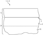
- the figure shows, as a sectional illustration in side view, a detail from a near-surface area of a blade 2 of a guide vane 1 of a steam turbine D.
- a guide vane 1 may be used in particular in a low-pressure area of the steam turbine D.
- a base body 3 made of steel of the guide vane 1 is first provided. Its initially still untreated surface 4 is then smoothed by polishing.
- the polished surface 4 is then nitrided e.g. using a plasma.
- a superficial area 5 of the base body 3 is formed as a layer-like corrosion-inhibiting area.
- An underlying area 6 is not nitrided.
- an organosilicon precursor e.g. Hexamethyldisiloxane and / or octamethylcyclosiloxane.
- a subsequent dense crosslinking of the precursor produces a silicon-organic coating 7 that reduces the size of water droplets on the surface 4.
- This coating has a water receding angle of at least 40 ° and a water contact angle of more than 50 °. In the low pressure area of the steam turbine D it shows no decomposition under hydrolytic influences.
- a number can also include exactly the specified number and a customary tolerance range, as long as this is not explicitly excluded.
Landscapes
- Engineering & Computer Science (AREA)
- Chemical & Material Sciences (AREA)
- Materials Engineering (AREA)
- Mechanical Engineering (AREA)
- General Engineering & Computer Science (AREA)
- Turbine Rotor Nozzle Sealing (AREA)
Description
- Die Erfindung betrifft ein Verfahren zum Herstellen einer Schaufel. Die Erfindung ist insbesondere anwendbar auf Leitschaufeln einer Dampfturbine.
- Die effiziente Erzeugung elektrischer Energie mit Hilfe von Dampfturbinenanlagen setzt voraus, dass entlang deren Strömungspfad ein möglichst hoher Anteil thermischer Energie des Strömungsmediums in kinetische Energie umgewandelt und zur Produktion von elektrischer Energie genutzt wird. Am kalten Ende einer Kondensationsdampfturbine, dem sogenannten Niederdruckbereich, ist dem Dampf derart viel innere Energie entzogen, dass sich aufgrund des geringen Kondensatordruckes eine Zweiphasenströmung ausbildet, die sowohl eine Gas- als auch eine Flüssigphase enthält. In der Strömung kommt es zum spontanen auskondensieren sogenannter Primärtropfen, die einen Durchmesser nicht mehr als einem Mikrometer aufweisen. Diese kleinen Tröpfchen in der Strömung werden von den Oberflächen der stationären Leitschaufeln aufgefangen und es bilden sich Wasseransammlungen, die in Richtung der Hinterkanten der Leitschaufeln wandern. Die sich an den Hinterkanten der Leitschaufeln ausbildenden Wasserfahnen werden von der Strömung in Form größerer Wassertropfen, sogenannten Sekundärtropfen mit Durchmessern zwischen 50 und 400 Mikrometern, mitgerissen. Aufgrund ihrer Größe und Masse und der damit einhergehenden Trägheit können diese Tropfen der Strömung nur sehr schlecht folgen und schlagen mit hoher Relativgeschwindigkeit auf die Vorderkanten der rotierenden Laufschaufeln. Der lokal sehr hohe Energieeintrag führt zur Ausbildung von Rissen auf der Laufschaufeloberfläche und kontinuierlicher Tropfenschlag bewirkt einen Materialabtrag an den Vorderkanten von Niederdruckschaufeln. Die Folgen von Tropfenschlagerosion und dadurch hervorgerufener Schädigung der Laufschaufeln sind Abnahme des Wirkungsgrades der Dampfturbine und erhöhter Wartungsaufwand.
-
DE 696 24 971 T2 offenbart eine Beschichtung zur Verhinderung von Fouling in Turbomaschinen mit einer Metalloberfläche, die umfasst: eine erste gehärtete Schicht eines haftenden Keramikmaterials mit anorganischem Phosphat als Opferanode, die in Kontakt mit der Oberfläche ist, eine zweite gehärtete Schicht, die in Kontakt mit der ersten Schicht ist und ein Bindemittel mit anorganischem Phosphat oder Silikat enthält und die nicht leitfähig ist und nicht als Opferanode dient, und eine gehärtete Deckschicht mit einer wärmestabilen organischen Polymer-Siegelmasse. -
DE 196 07 979 A1 offenbart einen Abgastrakt einer insbesondere zur Verbrennung von Schweröl einsetzbaren Verbrennungsvorrichtung. Dieser Abgastrakt soll das Problem lösen, die Anlagerung von Schmutzschichten im Abgastrakt einer insbesondere zur Verbrennung von Schweröl einsetzbaren Verbrennungsvorrichtung und an den zur Nutzbarmachung der Abgasenergie der Verbrennungsvorrichtung im Abgastrakt angeordneten Bauteile zu vermindern. Dies soll dadurch erreicht werden, dass auf der Oberfläche des zumindest einen, zur Nutzbarmachung der Abgasenergie im Abgastrakt angeordneten Bauteils bzw. zumindest eines dieser Bauteile und/oder auf der Oberfläche des Abgastraktes selbst eine Anti-Haftbeschichtung angeordnet ist. -
DE 37 24 626 A1 offenbart ein mit einem Überzug versehenes Schaufelblatt für Dampfturbinen, sich auszeichnet durch das eigentliche Schaufelblatt und einen einschichtigen Überzug aus harter verschleißfester Keramik oder einen mehrschichtigen Überzug bestehend aus einer Unterschicht aus aktivem Metall wie Cr und Ti und einer Deckschicht aus Keramik, wobei der Keramiküberzug durch Ionplating gebildet wird. Ein Verfahren gemäßDE 37 24 626 A1 dient zum Beschichten einer Schaufel für Dampfturbinen, ausgezeichnet durch Oberflächenbehandeln der Schaufeloberfläche, bis die Oberflächenrauheit auf Rmax 1-2 S verringert ist und durch Bilden eines einschichtigen oder mehrschichtigen Überzugs aus Keramik durch Ionplating. -
WO 98/18977 -
DE 100 56 241 A1 offenbart eine Niederdruckturbine, die Leitschaufeln und Laufschaufeln aufweist, deren Schaufelblätter eine Beschichtung aufweisen, die hydrophob oder wasserabweisend ist und eine glatte Oberfläche aufweist. Vorzugsweise enthält die Beschichtung amorphen Kohlenstoff. Die hydrophobe Eigenschaft der Beschichtung bewirkt, dass kleine in der Dampfphase enthaltene Tröpfchen beim Auftreffen auf ein beschichtetes Schaufelblatt als kleine Tröpfchen über das Schaufelblatt hinwegrollen und der Dampfströmung weiter folgen. Dadurch werden Nässeverluste vermieden und der Wirkungsgrad der Turbine erhöht. Weiter wird verhindert, dass die kleinen Tröpfchen auf den Schaufelblättern nicht zu größeren Tropfen oder einem Flüssigkeitsfilm koaleszieren. Tropfenschlagerosion an Schaufeln und weiteren Bauteilen der Turbine durch große Tropfen wird dadurch vermieden. -
US2013032316 betrifft ein Verfahren zur nasschemischen Beschichtung und Imprägnierung von Oberflächen. Es ist die Aufgabe der vorliegenden Erfindung, die Nachteile des Standes der Technik zumindest teilweise zu überwinden und insbesondere eine Möglichkeit zur besonders effektiven und preisgünstig umsetzbaren Verminderung einer Tropfenschlagerosion von Laufschaufeln einer Dampfturbine bereitzustellen. - Diese Aufgabe wird gemäß den Merkmalen des unabhängigen Anspruchs gelöst. Bevorzugte Ausführungsformen sind insbesondere den abhängigen Ansprüchen entnehmbar.
- Die Aufgabe wird gelöst durch eine Schaufel, insbesondere Leitschaufel, einer Turbine, insbesondere Dampfturbine, deren Schaufelblatt zumindest bereichsweise eine Beschichtung (im Folgenden ohne Beschränkung der Allgemeinheit als "wassertropfengrößen-reduzierende" Beschichtung bezeichnet) aufweist, deren Wasserrückzugswinkel mindestens 40° beträgt. Eine solche Schaufel, insbesondere Leitschaufel, weist den Vorteil auf, dass sie zuverlässig in der Lage ist, sich von ihrer Hinterkante der Leitschaufeln lösende Wassertropfen klein zu halten, insbesondere mit mittleren Tropfengrößen von wenigen Mikrometern oder noch weniger. Dabei wird ausgenutzt, dass ein Wasserrückzugswinkel von mindestens 40° dazu führt, dass selbst kleinsten Tröpfchen sich auf der Beschichtung bewegen können, ohne dass sie sich erst zu größeren Wasseransammlungen zusammenschließen müssen. In Folge dessen erreichen auch kleine und kleinste Tröpfchen die Leitschaufelkanten und lösen sich dort ab, ohne durch weiteres Zusammenschließen eine Mindestgröße erreichen zu müssen. Derart kleine Wassertropfen können weitgehend oder sogar praktisch vollständig von einem Dampfstrom in einer Dampfturbine so stark mitgenommen werden, dass sie nicht mehr auf zugehörige Laufschaufeln treffen. Treffen sie doch auf eine Laufschaufel, so setzen sie aufgrund ihrer geringen Masse bei einem Auftreffen auf die Laufschaufel eine nur geringe kinetische Energie frei. Durch beides wird eine Tropfenschlagerosion an der Laufschaufel verringert und somit deren Lebensdauer verlängert. Der Wasserrückzugswinkel von mindestens 40° ermöglicht zudem den Einsatz preiswerter wassertropfengrößenreduzierender Beschichtungen, die sich zudem einfach auf ein Schaufelblatt aufbringen lassen.
- Der Wasserrückzugswinkel kann insbesondere mit der statischen Tropfenmethode gemessen werden.
- Es ist eine Ausgestaltung, dass der Wasserrückzugswinkel mindestens 45°, insbesondere mindestens 50°, insbesondere mindestens 55° beträgt. Eine besonders bevorzugte Ausgestaltung hat sich bei einem Wasserrückzugswinkel von mindestens 60° ergeben. Der Wasserrückzugswinkel mag aber noch größer sein, z.B. mindestens 65° oder mindestens 70° betragen.
- Es ist noch eine Ausgestaltung, dass die Beschichtung aus mindestens einem hochtemperaturbeständigen Polymer mit einer geringen Zahl an polaren Gruppen besteht. Solche Polymere sind einfach und preiswert beziehbar und auf das Schaufelblatt aufbringbar. Zudem zeigen sie in ihrem vorgesehenen Temperaturbereich, der zum Einsatz in einer Dampfturbine geeignet ist, keine Zersetzung unter hydrolytischen Einflüssen. Die geringe Zahl an polaren Gruppen mag auch eine Abwesenheit polarer Gruppen umfassen.
- Es ist eine Ausgestaltung davon, dass mindestens ein Polymer mindestens einen zumindest teilfluorierten Kohlenwasserstoff aufweist bzw. auf dessen Basis hergestellt worden ist. Das auf mindestens einem teilfluorierten Kohlenwasserstoff basierte mindestens eine Polymer mag beispielsweise mindestens einen Fluorkunststoff aufweisen, insbesondere mindestens ein Polyhalogenolefin, z.B. Polytetrafluorethylen (Kurzzeichen PTFE) und/oder Polychlortrifluorethylen (Kurzzeichen PCTFE). PTFE ist sehr beständig gegenüber vielen Chemikalien und temperaturbeständig bis ca. 260 °C. PTFE hat ferner einen sehr geringen Reibungskoeffizienten. Außerdem ist die Haftreibung genauso groß wie die Gleitreibung, so dass der Übergang vom Stillstand zur Bewegung ohne Ruck stattfindet. Seine Oberflächenspannung ist extrem niedrig. PTFE ist schwierig zu benetzen und kaum zu verkleben. Ein Kontaktwinkel mit Wasser beträgt 126°. Auch PCTFE ist sehr beständig gegenüber vielen Chemikalien. Daneben besitzt PCTFE die höchste Härte, Festigkeit und Steifigkeit unter den Fluorkunststoffen. PCTFE ist formstabil, sehr gut mechanisch bearbeitbar und kann in einem weiten Temperaturbereich (etwa -240 °C bis +205 °C) eingesetzt werden.
- Ein bevorzugter Einsatzbereich von auf zumindest teilfluorierten Kohlenwasserstoffen basierenden Polymeren reicht von ca. 100 °C bis ca. 180 °C.
- Es ist noch eine Ausgestaltung davon, dass mindestens ein Polymer mindestens ein Polyoleofin aufweist. Diese Polyoleofin sind besonders preiswert und einfach handhabbar. Ein bevorzugter Einsatzbereich von Polyoleofinen reicht bis ca. 100 °C. Beispiele für auf Leitschaufeln nutzbare Polyoleofine umfassen Polyethylen und/oder Polypropylen.
- Es ist eine weitere Ausgestaltung davon, dass mindestens ein Polymer mindestens ein Polyetherketon, mindestens ein Polyimid und/oder mindestens ein Polysulfon aufweist. Ein bevorzugter Einsatzbereich dieser Polymere beginnt ab ca. 200 °C.
- Es ist ein Teil der Erfindung, dass die wassertropfengrößen-reduzierende Beschichtung mit mindestens einem siliziumorganischen Präkursor hergestellt worden ist. Der Präkursor weist insbesondere nur unpolare Gruppen auf. Auch ein siliziumorganischer Präkursor weist in einer für einen Niederdruckbereich einer Dampfturbine typischen Umgebung keine Zersetzung unter hydrolytischen Einflüssen auf.
- Es ist eine Weiterbildung, dass dazu mindestens ein siliziumorganischer Präkursor aufgebracht worden, welcher sich folgend dicht vernetzt. Die Gruppen des Präkursors bleiben dabei vorzugsweise weitgehend erhalten, wandeln sich also im Wesentlichen nicht chemisch um.
- Es ist auch eine Ausgestaltung, dass der Präkursor mindestens eine Alkylgruppe, mindestens eine Arylgruppe und/oder mindestens eine cycloaromatische Gruppe, insbesondere Benzylgruppe, aufweist.
- Es ist außerdem eine Ausgestaltung, dass der mindestens eine siliziumorganische Präkursor mindestens ein Siloxan, insbesondere Hexamethyldisiloxan und/oder Octamethylcyclosiloxan, aufweist.
- Es ist zudem eine Ausgestaltung, dass ein Wasserkontaktwinkel mindestens 50°, insbesondere mindestens 75°, beträgt. Dadurch kann die Beweglichkeit des Wassers auf dem Schaufelblatt weiter gesteigert werden. Die wassertropfengrößen-reduzierende Beschichtung mag also hydrophob sein, braucht es aber nicht zu sein, um die geringe Tröpfchengröße zu erreichen. Der Wasserkontaktwinkel mag also z.B. kleiner als 90° sein, insbesondere auch kleiner als 85°, insbesondere kleiner als 80°.
- Es ist eine zur Verlängerung einer Lebensdauer vorteilhafte Ausgestaltung, dass die wassertropfengrößen-reduzierende Beschichtung auf einer Korrosionsschutzoberfläche des Schaufelblatts aufgebracht ist. Dadurch kann eine korrosive Beschädigung des Schaufelblatts, welche eine mittlere Tröpfchengröße der sich von der Leitschaufel ablösenden Wassertröpfchen, verringert oder sogar ganz verhindert werden.
- Das Aufbringen der wassertropfengrößen-reduzierenden Beschichtung mag beispielsweise nasschemisch oder im Rahmen eines Plasmaprozesses durchgeführt werden. Der Plasmaprozess mag z.B. Atmosphärendruckplasma oder Niederdruckplasma nutzen. Eine Auftragung mag auch durch Lackieren (mit Lösungsmittel oder durch Verwendung von Pulverlack), Aufsprühen, oder Folieren erfolgen.
- Es ist eine Ausgestaltung davon, dass die Korrosionsschutzoberfläche eine Oberfläche einer Korrosionsschutzschicht ist, z.B. aus Metall (insbesondere Chrom) oder Polymer. Dies ermöglicht eine besonders große Auswahl an einsetzbaren korrosionsschützenden Materialien. Die Korrosionsschutzschicht kann auch als eine korrosionshemmende Sperrschicht bezeichnet werden. Die Korrosionsschutzschicht mag direkt oder indirekt (z.B. über mindestens eine Zwischenschicht) auf einem Grundkörper des Schaufelblatts aufgebracht sein. Die Korrosionsschutzschicht mag beispielsweise durch Galvanisieren, PVD, CVD usw. aufgebracht werden
- Es ist noch eine Ausgestaltung davon, dass die Korrosionsschutzoberfläche eine Oberfläche eines korrosionsfesten Grundkörpers des Schaufelblatts oder eine oberflächenpassivierte Oberfläche eines Grundkörpers des Schaufelblatts ist. Durch eine solche korrosionsschützende Behandlung der Oberfläche des Grundkörpers des Schaufelblatts kann auf eine eigenständige Korrosionsschutzschicht verzichtet werden. Eine Oberflächenpassivierung mag z.B. durch Nitrieren oder Phosphatieren umgesetzt werden, z.B. eines Grundkörpers aus Stahl. Das Nitrieren kann beispielsweise mittels eines Plasmaprozess durchgeführt werden.
- Der Grundkörper des Schaufelblatts bestimmt eine grundsätzliche Form, Größe und mechanische und thermische Eigenschaft des Schaufelblatts. Der Grundkörper mag z.B. ein metallischer Gusskörper sein, insbesondere aus Stahl, und z.B. auch als "Schaufelblatt als solches" bezeichnet werden. Der Grundkörper ist insbesondere ein Vollkörper. Er mag ein ausgefüllter Körper oder ein Hohlkörper sein.
- Die wassertropfengrößen-reduzierende Beschichtung mag direkt oder indirekt (z.B. über mindestens eine Zwischenschicht) auf einer Korrosionsschutzoberfläche des Schaufelblatts aufgebracht sein.
- Es ist eine weitere zur Reduzierung einer Wassertropfengröße vorteilhafte Ausgestaltung, dass eine Oberfläche eines Grundkörpers des Schaufelblatts eine geglättete Oberfläche ist. Eine solche geglättete Oberfläche kann sich vorteilhaft auf eine Glattheit der wassertropfengrößen-reduzierenden Beschichtung auswirken.
- Außer einer Leitschaufel mag z.B. auch eine Laufschaufel entsprechend ausgebildet sein.
- Die Aufgabe wird auch gelöst durch eine Dampfturbine mit mindestens einer Schaufel, insbesondere Leitschaufel, wie oben beschrieben. Die Dampfturbine ist vorzugsweise eine Kondensationsdampfturbine. Die mindestens eine Schaufel, insbesondere Leitschaufel, befindet sich insbesondere in einem Niederdruckbereich der Dampfturbine.
- Die Aufgabe wird auch gelöst durch ein Verfahren zum Herstellen einer Schaufel, insbesondere Leitschaufel, wie oben beschrieben. Das Verfahren kann analog zu der Leitschaufel ausgebildet werden und ergibt sie gleichen Vorteile.
- Es ist eine Ausgestaltung, dass das Verfahren zum Herstellen der Schaufel mit einer wassertropfengrößen-reduzierenden Beschichtung mit mindestens einem siliziumorganischen Präkursor dient, bei dem auf einen Grundkörper des Schaufelblatts oder auf eine auf den Grundkörper aufgebrachte Korrosionsschutzschicht mindestens ein siliziumorganischer Präkursor aufgebracht wird, welcher sich folgend vernetzt.
- Es ist ein Teil der Erfindung, dass zum Herstellen einer geglätteten Oberfläche des Grundkörpers des Schaufelblatts der Grundkörper bereits glatter hergestellt wird. Dies kann beispielsweise durch Verbesserungen im Herstellungsprozess erreicht werden. Solche Verbesserungen mögen eine Nutzung eines feineren Sand im Formenbau einer Gussform des Grundkörpers und/oder eines glatteren Ausgangsmaterials beim Schweißen bestehen. Alternativ oder Zusätzlich mag die Oberfläche des Grundkörpers des Schaufelblatts poliert werden. Eine weitere, alternative oder zusätzliche, Maßnahme besteht im Aufbringen einer topographienivellierenden Beschichtung auf den Grundkörper.
- Insbesondere können folgende Vorgehensweisen beispielhaft genutzt werden, z.B. nach Bereitstellung eines Grundkörpers einer Schaufel aus Stahl:
- a) Glättung der Oberfläche zumindest des Schaufelblatts durch Polieren, anschließende Nitrierung der Oberfläche (z.B. unter Verwendung eines Plasmas) zum Erreichen einer korrosionshemmenden Sperrschicht und anschließende Beschichtung der nitrierten Oberfläche in einem Atmosphärendruckplasma oder einem Niederdruckplasma mit einem siliziumorganischen Präkursor (z.B. Hexamethyldisiloxan oder Octamethylcyclosiloxan) zum Herstellen der wassertropfengrößen-reduzierenden Beschichtung. Dieses oben genannten Verfahren gehört auch zur Erfindung.
- b) Glättung der Oberfläche zumindest des Schaufelblatts durch Polieren, anschließender Auftrag einer Korrosionsschutzschicht durch Galvanisieren (z.B. durch einen Auftrag einer Chromschicht und anschließender nasschemischer oder plasmatechnischer Auftrag einer wassertropfengrößen-reduzierenden Beschichtung.
- c) Auftrag einer Korrosionsschutzschicht durch Nitrieren oder Phosphatieren, anschließend Glättung der Oberfläche und anschließend Auftrag einer polymeren Oberfläche z.B. durch Lackieren oder Folieren. Dieses Beispiel ist besonders geeignet für Polymere wie PEEK, Polyimid(e) und/oder Polyethersulfon(e).
- Die oben beschriebenen Eigenschaften, Merkmale und Vorteile dieser Erfindung sowie die Art und Weise, wie diese erreicht werden, werden klarer und deutlicher verständlich im Zusammenhang mit der folgenden schematischen Beschreibung eines Ausführungsbeispiels, das im Zusammenhang mit den Zeichnungen näher erläutert wird. Dabei können zur Übersichtlichkeit gleiche oder gleichwirkende Elemente mit gleichen Bezugszeichen versehen sein.
- Die Figur zeigt als Schnittdarstellung in Seitenansicht einen Ausschnitt aus einem oberflächennahen Bereich eines Schaufelblatts 2 einer Leitschaufel 1 einer Dampfturbine D. Eine solche Leitschaufel 1 mag insbesondere in einem Niederdruckbereich der Dampfturbine D verwendet werden.
- Dazu wird zunächst ein Grundkörper 3 aus Stahl der Leitschaufel 1 bereitgestellt. Folgend wird seine zunächst noch unbehandelte Oberfläche 4 durch Polieren geglättet.
- Anschließend erfolgt die Nitrierung der polierten Oberfläche 4 z.B. unter Verwendung eines Plasmas. So wird ein oberflächlicher Bereich 5 des Grundkörpers 3 als ein schichtartiger korrosionshemmender Bereich ausgebildet. Ein darunterliegender Bereich 6 wird nicht nitriert.
- Es erfolgt eine anschließende Beschichtung der nun aufgrund der Nitrierung als Korrosionsschutzoberfläche dienenden Oberfläche 4 in einem Atmosphärendruckplasma oder einem Niederdruckplasma mit einem siliziumorganischen Präkursor, z.B. Hexamethyldisiloxan und/oder Octamethylcyclosiloxan. Durch eine sich anschließende dichte Vernetzung des Präkursors wird auf der Oberfläche 4 eine wassertropfengrößen-reduzierende siliziumorganische Beschichtung 7 erzeugt. Diese Beschichtung weist einen Wasserrückzugswinkel von mindestens 40° und einen Wasserkontaktwinkel von mehr als 50° auf. Sie zeigt in dem Niederdruckbereich der Dampfturbine D keine Zersetzung unter hydrolytischen Einflüssen.
- Obwohl die Erfindung im Detail durch das gezeigte Ausführungsbeispiel näher illustriert und beschrieben wurde, so ist die Erfindung nicht darauf eingeschränkt und andere Variationen können vom Fachmann hieraus abgeleitet werden, ohne den Schutzumfang der Erfindung zu verlassen.
- Allgemein kann unter "ein", "eine" usw. eine Einzahl oder eine Mehrzahl verstanden werden, insbesondere im Sinne von "mindestens ein" oder "ein oder mehrere" usw., solange dies nicht explizit ausgeschlossen ist, z.B. durch den Ausdruck "genau ein" usw.
- Auch kann eine Zahlenangabe genau die angegebene Zahl als auch einen üblichen Toleranzbereich umfassen, solange dies nicht explizit ausgeschlossen ist.
Claims (7)
- Verfahren zum Herstellen einer Schaufel, insbesondere einer Leitschaufel (1) einer Dampfturbine, bei dem- ein geglätteter Grundkörper (3) eines Schaufelblatts (2) bereitgestellt wird, mit folgender Vorgehensweise:- Bildung einer Korrosionsschutzschicht (5) auf dem geglätteten Grundkörper (3) durch Nitrierung oder Phosphatierung, und- Beschichtung der Oberfläche (4) der Korrosionsschutzschicht (5) in einem Atmosphärendruckplasma oder einem Niederdruckplasma mit einem siliziumorganischen Präkursor,- durch dessen im Folgenden durchgeführte dichte Vernetzung auf der Oberfläche (4) eine wassertropfengrößen-reduzierende siliziumorganische Beschichtung (7) erzeugt wird.
- Verfahren nach Anspruch 1, wobei der siliziumorganische Präkursor über ein Plasma aufgebracht wird.
- Verfahren nach Anspruch 2, wobei der siliziumorganische Präkursor über ein Atmosphärendruckplasma aufgebracht wird.
- Verfahren nach einem der vorstehenden Ansprüche, wobei der siliziumorganische Präkursor zumindest ein Siloxan umfasst.
- Verfahren nach einem der vorstehenden Ansprüche, wobei der siliziumorganische Präkursor zumindest ein Hexamethyldisiloxan umfasst.
- Verfahren nach einem der vorstehenden Ansprüche, wobei der siliziumorganische Präkursor zumindest ein Octamethylcyclosiloxan umfasst.
- Verfahren nach einem der vorstehenden Ansprüche, wobei die wassertropfengrößen-reduzierende siliziumorganische Beschichtung einen Wasserrückzugswinkel von mindestens 40° aufweist.
Applications Claiming Priority (1)
| Application Number | Priority Date | Filing Date | Title |
|---|---|---|---|
| DE102014219653.1A DE102014219653A1 (de) | 2014-09-29 | 2014-09-29 | Schaufel einer Turbine mit beschichtetem Schaufelblatt |
Publications (2)
| Publication Number | Publication Date |
|---|---|
| EP3000977A1 EP3000977A1 (de) | 2016-03-30 |
| EP3000977B1 true EP3000977B1 (de) | 2020-11-04 |
Family
ID=54065798
Family Applications (1)
| Application Number | Title | Priority Date | Filing Date |
|---|---|---|---|
| EP15184244.0A Not-in-force EP3000977B1 (de) | 2014-09-29 | 2015-09-08 | Schaufel einer turbine mit wasserabweisendem beschichtetem schaufelblatt |
Country Status (2)
| Country | Link |
|---|---|
| EP (1) | EP3000977B1 (de) |
| DE (1) | DE102014219653A1 (de) |
Families Citing this family (2)
| Publication number | Priority date | Publication date | Assignee | Title |
|---|---|---|---|---|
| WO2017222516A1 (en) * | 2016-06-22 | 2017-12-28 | Siemens Aktiengesellschaft | Method and system for reducing liquid droplet impact damage by superhydrophobic surfaces |
| DE112018000210T5 (de) * | 2017-01-09 | 2019-08-29 | Cummins Filtration Ip, Inc. | Impulsturbine mit nicht benetzender Oberfläche für verbesserten hydraulischen Wirkungsgrad |
Family Cites Families (9)
| Publication number | Priority date | Publication date | Assignee | Title |
|---|---|---|---|---|
| DE3724626A1 (de) | 1986-07-31 | 1988-02-04 | Mitsubishi Heavy Ind Ltd | Beschichtete schaufel fuer dampfturbinen und hierfuer anzuwendendes beschichtungsverfahren |
| DE69624971T2 (de) | 1995-04-25 | 2003-07-17 | Sermatch International Inc., Limerick | Fäulnisverhinderndes Überzugsmittel für Turbomaschinen |
| DE19607979A1 (de) | 1996-03-01 | 1997-09-04 | Asea Brown Boveri | Abgastrakt einer insbesondere zur Verbrennung von Schweröl einsetzbaren Verbrennungsvorrichtung |
| DE19644692A1 (de) | 1996-10-28 | 1998-04-30 | Abb Patent Gmbh | Beschichtung sowie ein Verfahren zu deren Herstellung |
| DE10056241B4 (de) | 2000-11-14 | 2010-12-09 | Alstom Technology Ltd. | Niederdruckdampfturbine |
| US20080145631A1 (en) * | 2006-12-19 | 2008-06-19 | General Electric Company | Articles having antifouling surfaces and methods for making |
| BR112014002627A2 (pt) * | 2011-08-03 | 2017-03-01 | Massachusetts Inst Technology | artigos para manipulação de líquidos colididos e métodos de fabricação dos mesmos |
| BR112014002585B8 (pt) * | 2011-08-05 | 2022-09-06 | Massachusetts Inst Technology | Artigo compreendendo superfícies impregnadas com líquido |
| WO2014145586A1 (en) * | 2013-03-15 | 2014-09-18 | Jonathan David Smith | Methods and articles for liquid-impregnated surfaces for the inhibition of vapor or gas nucleation |
-
2014
- 2014-09-29 DE DE102014219653.1A patent/DE102014219653A1/de not_active Withdrawn
-
2015
- 2015-09-08 EP EP15184244.0A patent/EP3000977B1/de not_active Not-in-force
Non-Patent Citations (1)
| Title |
|---|
| None * |
Also Published As
| Publication number | Publication date |
|---|---|
| EP3000977A1 (de) | 2016-03-30 |
| DE102014219653A1 (de) | 2016-03-31 |
Similar Documents
| Publication | Publication Date | Title |
|---|---|---|
| DE102009010110B4 (de) | Erosionsschutz-Beschichtungssystem für Gasturbinenbauteile | |
| DE102013009369B4 (de) | Verfahren zur Herstellung eines Kolbenrings | |
| EP2576862B1 (de) | Verfahren zum kaltgasspritzen einer schicht mit einer metallischen gefügephase und einer gefügephase aus kunststoff, bauteil mit einer solchen schicht sowie verwendungen dieses bauteils | |
| DE102011075810A1 (de) | Korrosionsbeständige walzenbeschichtung | |
| EP2352907B1 (de) | Erosionsschutzschicht für aerodynamische komponenten und strukturen und verfahren zu ihrer herstellung | |
| DE102014109339A1 (de) | Beschichtung, beschichtete Turbinenkomponente und Beschichtungsverfahren | |
| WO2015113532A1 (de) | Aerodynamisches luftlager und verfahren zu dessen herstellung | |
| WO2009079979A1 (de) | Lageranordnung | |
| EP3000977B1 (de) | Schaufel einer turbine mit wasserabweisendem beschichtetem schaufelblatt | |
| AT510190A1 (de) | Verfahren zum herstellen eines mehrschichtigen gleitlagers | |
| DE112015003695B4 (de) | Dampfturbinenrotorblatt, Verfahren zum Herstellen eines Dampfturbinenrotorblatts, und Dampfturbine | |
| DE102007050141A1 (de) | Verschleißschutzbeschichtung | |
| DE102010005389A1 (de) | Strukturierte Oberflächenbeschichtung mittels kinetischem Kaltgasspritzen | |
| DE102010004661B4 (de) | Vanadium basierte Hartstoffbeschichtung einer Windkraftanlagenkomponente | |
| DE102006009116A1 (de) | Korrosionsbeständiges Substrat und Verfahren zu dessen Herstellung | |
| EP3601629B1 (de) | Kolbenring mit kugelgestrahlter einlaufschicht und verfahren zur herstellung | |
| DE102016108088B4 (de) | Beschichteter Kolbenring mit Schutzschicht | |
| WO2014190984A1 (de) | Beschichtetes bauteil | |
| WO1998018977A1 (de) | Beschichtung für bauelemente sowie ein verfahren zu deren herstellung | |
| EP1711773A1 (de) | Wärmetauscherrohr, wärmetauscher und verwendung | |
| WO2008003273A2 (de) | Korrosionbeständiges substrat mit einer cr(vi)-freien dreilagigen beschichtung und verfahren zu dessen herstellung | |
| EP3245378B1 (de) | Lösbare gewindeverbindung mit asymmetrischer beschichtung | |
| WO2017206981A1 (de) | Wälzlager mit einer beschichtung | |
| EP3421745B1 (de) | Baueinheit für eine abgasanlage | |
| DE102004014871A1 (de) | Kolbenring |
Legal Events
| Date | Code | Title | Description |
|---|---|---|---|
| PUAI | Public reference made under article 153(3) epc to a published international application that has entered the european phase |
Free format text: ORIGINAL CODE: 0009012 |
|
| AK | Designated contracting states |
Kind code of ref document: A1 Designated state(s): AL AT BE BG CH CY CZ DE DK EE ES FI FR GB GR HR HU IE IS IT LI LT LU LV MC MK MT NL NO PL PT RO RS SE SI SK SM TR |
|
| AX | Request for extension of the european patent |
Extension state: BA ME |
|
| 17P | Request for examination filed |
Effective date: 20160504 |
|
| RBV | Designated contracting states (corrected) |
Designated state(s): AL AT BE BG CH CY CZ DE DK EE ES FI FR GB GR HR HU IE IS IT LI LT LU LV MC MK MT NL NO PL PT RO RS SE SI SK SM TR |
|
| STAA | Information on the status of an ep patent application or granted ep patent |
Free format text: STATUS: REQUEST FOR EXAMINATION WAS MADE |
|
| RAP1 | Party data changed (applicant data changed or rights of an application transferred) |
Owner name: SIEMENS AKTIENGESELLSCHAFT |
|
| STAA | Information on the status of an ep patent application or granted ep patent |
Free format text: STATUS: EXAMINATION IS IN PROGRESS |
|
| 17Q | First examination report despatched |
Effective date: 20191004 |
|
| GRAP | Despatch of communication of intention to grant a patent |
Free format text: ORIGINAL CODE: EPIDOSNIGR1 |
|
| STAA | Information on the status of an ep patent application or granted ep patent |
Free format text: STATUS: GRANT OF PATENT IS INTENDED |
|
| INTG | Intention to grant announced |
Effective date: 20200608 |
|
| GRAS | Grant fee paid |
Free format text: ORIGINAL CODE: EPIDOSNIGR3 |
|
| GRAA | (expected) grant |
Free format text: ORIGINAL CODE: 0009210 |
|
| STAA | Information on the status of an ep patent application or granted ep patent |
Free format text: STATUS: THE PATENT HAS BEEN GRANTED |
|
| AK | Designated contracting states |
Kind code of ref document: B1 Designated state(s): AL AT BE BG CH CY CZ DE DK EE ES FI FR GB GR HR HU IE IS IT LI LT LU LV MC MK MT NL NO PL PT RO RS SE SI SK SM TR |
|
| REG | Reference to a national code |
Ref country code: GB Ref legal event code: FG4D Free format text: NOT ENGLISH |
|
| REG | Reference to a national code |
Ref country code: CH Ref legal event code: EP |
|
| REG | Reference to a national code |
Ref country code: AT Ref legal event code: REF Ref document number: 1331058 Country of ref document: AT Kind code of ref document: T Effective date: 20201115 |
|
| REG | Reference to a national code |
Ref country code: DE Ref legal event code: R096 Ref document number: 502015013737 Country of ref document: DE |
|
| REG | Reference to a national code |
Ref country code: IE Ref legal event code: FG4D Free format text: LANGUAGE OF EP DOCUMENT: GERMAN |
|
| REG | Reference to a national code |
Ref country code: DE Ref legal event code: R081 Ref document number: 502015013737 Country of ref document: DE Owner name: SIEMENS ENERGY GLOBAL GMBH & CO. KG, DE Free format text: FORMER OWNER: SIEMENS AKTIENGESELLSCHAFT, 80333 MUENCHEN, DE |
|
| RAP2 | Party data changed (patent owner data changed or rights of a patent transferred) |
Owner name: SIEMENS ENERGY GLOBAL GMBH & CO. KG |
|
| REG | Reference to a national code |
Ref country code: NL Ref legal event code: MP Effective date: 20201104 |
|
| PG25 | Lapsed in a contracting state [announced via postgrant information from national office to epo] |
Ref country code: NO Free format text: LAPSE BECAUSE OF FAILURE TO SUBMIT A TRANSLATION OF THE DESCRIPTION OR TO PAY THE FEE WITHIN THE PRESCRIBED TIME-LIMIT Effective date: 20210204 Ref country code: PT Free format text: LAPSE BECAUSE OF FAILURE TO SUBMIT A TRANSLATION OF THE DESCRIPTION OR TO PAY THE FEE WITHIN THE PRESCRIBED TIME-LIMIT Effective date: 20210304 Ref country code: FI Free format text: LAPSE BECAUSE OF FAILURE TO SUBMIT A TRANSLATION OF THE DESCRIPTION OR TO PAY THE FEE WITHIN THE PRESCRIBED TIME-LIMIT Effective date: 20201104 Ref country code: RS Free format text: LAPSE BECAUSE OF FAILURE TO SUBMIT A TRANSLATION OF THE DESCRIPTION OR TO PAY THE FEE WITHIN THE PRESCRIBED TIME-LIMIT Effective date: 20201104 Ref country code: GR Free format text: LAPSE BECAUSE OF FAILURE TO SUBMIT A TRANSLATION OF THE DESCRIPTION OR TO PAY THE FEE WITHIN THE PRESCRIBED TIME-LIMIT Effective date: 20210205 |
|
| PG25 | Lapsed in a contracting state [announced via postgrant information from national office to epo] |
Ref country code: IS Free format text: LAPSE BECAUSE OF FAILURE TO SUBMIT A TRANSLATION OF THE DESCRIPTION OR TO PAY THE FEE WITHIN THE PRESCRIBED TIME-LIMIT Effective date: 20210304 Ref country code: LV Free format text: LAPSE BECAUSE OF FAILURE TO SUBMIT A TRANSLATION OF THE DESCRIPTION OR TO PAY THE FEE WITHIN THE PRESCRIBED TIME-LIMIT Effective date: 20201104 Ref country code: PL Free format text: LAPSE BECAUSE OF FAILURE TO SUBMIT A TRANSLATION OF THE DESCRIPTION OR TO PAY THE FEE WITHIN THE PRESCRIBED TIME-LIMIT Effective date: 20201104 Ref country code: SE Free format text: LAPSE BECAUSE OF FAILURE TO SUBMIT A TRANSLATION OF THE DESCRIPTION OR TO PAY THE FEE WITHIN THE PRESCRIBED TIME-LIMIT Effective date: 20201104 Ref country code: BG Free format text: LAPSE BECAUSE OF FAILURE TO SUBMIT A TRANSLATION OF THE DESCRIPTION OR TO PAY THE FEE WITHIN THE PRESCRIBED TIME-LIMIT Effective date: 20210204 Ref country code: ES Free format text: LAPSE BECAUSE OF FAILURE TO SUBMIT A TRANSLATION OF THE DESCRIPTION OR TO PAY THE FEE WITHIN THE PRESCRIBED TIME-LIMIT Effective date: 20201104 |
|
| REG | Reference to a national code |
Ref country code: LT Ref legal event code: MG9D |
|
| PG25 | Lapsed in a contracting state [announced via postgrant information from national office to epo] |
Ref country code: HR Free format text: LAPSE BECAUSE OF FAILURE TO SUBMIT A TRANSLATION OF THE DESCRIPTION OR TO PAY THE FEE WITHIN THE PRESCRIBED TIME-LIMIT Effective date: 20201104 |
|
| PG25 | Lapsed in a contracting state [announced via postgrant information from national office to epo] |
Ref country code: LT Free format text: LAPSE BECAUSE OF FAILURE TO SUBMIT A TRANSLATION OF THE DESCRIPTION OR TO PAY THE FEE WITHIN THE PRESCRIBED TIME-LIMIT Effective date: 20201104 Ref country code: RO Free format text: LAPSE BECAUSE OF FAILURE TO SUBMIT A TRANSLATION OF THE DESCRIPTION OR TO PAY THE FEE WITHIN THE PRESCRIBED TIME-LIMIT Effective date: 20201104 Ref country code: SK Free format text: LAPSE BECAUSE OF FAILURE TO SUBMIT A TRANSLATION OF THE DESCRIPTION OR TO PAY THE FEE WITHIN THE PRESCRIBED TIME-LIMIT Effective date: 20201104 Ref country code: SM Free format text: LAPSE BECAUSE OF FAILURE TO SUBMIT A TRANSLATION OF THE DESCRIPTION OR TO PAY THE FEE WITHIN THE PRESCRIBED TIME-LIMIT Effective date: 20201104 Ref country code: EE Free format text: LAPSE BECAUSE OF FAILURE TO SUBMIT A TRANSLATION OF THE DESCRIPTION OR TO PAY THE FEE WITHIN THE PRESCRIBED TIME-LIMIT Effective date: 20201104 Ref country code: CZ Free format text: LAPSE BECAUSE OF FAILURE TO SUBMIT A TRANSLATION OF THE DESCRIPTION OR TO PAY THE FEE WITHIN THE PRESCRIBED TIME-LIMIT Effective date: 20201104 |
|
| REG | Reference to a national code |
Ref country code: DE Ref legal event code: R097 Ref document number: 502015013737 Country of ref document: DE |
|
| PG25 | Lapsed in a contracting state [announced via postgrant information from national office to epo] |
Ref country code: DK Free format text: LAPSE BECAUSE OF FAILURE TO SUBMIT A TRANSLATION OF THE DESCRIPTION OR TO PAY THE FEE WITHIN THE PRESCRIBED TIME-LIMIT Effective date: 20201104 |
|
| PLBE | No opposition filed within time limit |
Free format text: ORIGINAL CODE: 0009261 |
|
| STAA | Information on the status of an ep patent application or granted ep patent |
Free format text: STATUS: NO OPPOSITION FILED WITHIN TIME LIMIT |
|
| 26N | No opposition filed |
Effective date: 20210805 |
|
| PG25 | Lapsed in a contracting state [announced via postgrant information from national office to epo] |
Ref country code: AL Free format text: LAPSE BECAUSE OF FAILURE TO SUBMIT A TRANSLATION OF THE DESCRIPTION OR TO PAY THE FEE WITHIN THE PRESCRIBED TIME-LIMIT Effective date: 20201104 Ref country code: NL Free format text: LAPSE BECAUSE OF FAILURE TO SUBMIT A TRANSLATION OF THE DESCRIPTION OR TO PAY THE FEE WITHIN THE PRESCRIBED TIME-LIMIT Effective date: 20201104 Ref country code: IT Free format text: LAPSE BECAUSE OF FAILURE TO SUBMIT A TRANSLATION OF THE DESCRIPTION OR TO PAY THE FEE WITHIN THE PRESCRIBED TIME-LIMIT Effective date: 20201104 |
|
| PGFP | Annual fee paid to national office [announced via postgrant information from national office to epo] |
Ref country code: FR Payment date: 20210920 Year of fee payment: 7 |
|
| PG25 | Lapsed in a contracting state [announced via postgrant information from national office to epo] |
Ref country code: SI Free format text: LAPSE BECAUSE OF FAILURE TO SUBMIT A TRANSLATION OF THE DESCRIPTION OR TO PAY THE FEE WITHIN THE PRESCRIBED TIME-LIMIT Effective date: 20201104 |
|
| REG | Reference to a national code |
Ref country code: CH Ref legal event code: PL |
|
| REG | Reference to a national code |
Ref country code: BE Ref legal event code: MM Effective date: 20210930 |
|
| GBPC | Gb: european patent ceased through non-payment of renewal fee |
Effective date: 20210908 |
|
| PG25 | Lapsed in a contracting state [announced via postgrant information from national office to epo] |
Ref country code: IS Free format text: LAPSE BECAUSE OF FAILURE TO SUBMIT A TRANSLATION OF THE DESCRIPTION OR TO PAY THE FEE WITHIN THE PRESCRIBED TIME-LIMIT Effective date: 20210304 Ref country code: MC Free format text: LAPSE BECAUSE OF FAILURE TO SUBMIT A TRANSLATION OF THE DESCRIPTION OR TO PAY THE FEE WITHIN THE PRESCRIBED TIME-LIMIT Effective date: 20201104 |
|
| PG25 | Lapsed in a contracting state [announced via postgrant information from national office to epo] |
Ref country code: LU Free format text: LAPSE BECAUSE OF NON-PAYMENT OF DUE FEES Effective date: 20210908 Ref country code: IE Free format text: LAPSE BECAUSE OF NON-PAYMENT OF DUE FEES Effective date: 20210908 Ref country code: GB Free format text: LAPSE BECAUSE OF NON-PAYMENT OF DUE FEES Effective date: 20210908 Ref country code: BE Free format text: LAPSE BECAUSE OF NON-PAYMENT OF DUE FEES Effective date: 20210930 |
|
| PG25 | Lapsed in a contracting state [announced via postgrant information from national office to epo] |
Ref country code: LI Free format text: LAPSE BECAUSE OF NON-PAYMENT OF DUE FEES Effective date: 20210930 Ref country code: CH Free format text: LAPSE BECAUSE OF NON-PAYMENT OF DUE FEES Effective date: 20210930 |
|
| PGFP | Annual fee paid to national office [announced via postgrant information from national office to epo] |
Ref country code: DE Payment date: 20220617 Year of fee payment: 8 |
|
| REG | Reference to a national code |
Ref country code: AT Ref legal event code: MM01 Ref document number: 1331058 Country of ref document: AT Kind code of ref document: T Effective date: 20210908 |
|
| PG25 | Lapsed in a contracting state [announced via postgrant information from national office to epo] |
Ref country code: AT Free format text: LAPSE BECAUSE OF NON-PAYMENT OF DUE FEES Effective date: 20210908 |
|
| PG25 | Lapsed in a contracting state [announced via postgrant information from national office to epo] |
Ref country code: HU Free format text: LAPSE BECAUSE OF FAILURE TO SUBMIT A TRANSLATION OF THE DESCRIPTION OR TO PAY THE FEE WITHIN THE PRESCRIBED TIME-LIMIT; INVALID AB INITIO Effective date: 20150908 |
|
| PG25 | Lapsed in a contracting state [announced via postgrant information from national office to epo] |
Ref country code: CY Free format text: LAPSE BECAUSE OF FAILURE TO SUBMIT A TRANSLATION OF THE DESCRIPTION OR TO PAY THE FEE WITHIN THE PRESCRIBED TIME-LIMIT Effective date: 20201104 |
|
| PG25 | Lapsed in a contracting state [announced via postgrant information from national office to epo] |
Ref country code: FR Free format text: LAPSE BECAUSE OF NON-PAYMENT OF DUE FEES Effective date: 20220930 |
|
| REG | Reference to a national code |
Ref country code: DE Ref legal event code: R119 Ref document number: 502015013737 Country of ref document: DE |
|
| PG25 | Lapsed in a contracting state [announced via postgrant information from national office to epo] |
Ref country code: MK Free format text: LAPSE BECAUSE OF FAILURE TO SUBMIT A TRANSLATION OF THE DESCRIPTION OR TO PAY THE FEE WITHIN THE PRESCRIBED TIME-LIMIT Effective date: 20201104 |
|
| PG25 | Lapsed in a contracting state [announced via postgrant information from national office to epo] |
Ref country code: TR Free format text: LAPSE BECAUSE OF FAILURE TO SUBMIT A TRANSLATION OF THE DESCRIPTION OR TO PAY THE FEE WITHIN THE PRESCRIBED TIME-LIMIT Effective date: 20201104 |
|
| PG25 | Lapsed in a contracting state [announced via postgrant information from national office to epo] |
Ref country code: DE Free format text: LAPSE BECAUSE OF NON-PAYMENT OF DUE FEES Effective date: 20240403 |
|
| PG25 | Lapsed in a contracting state [announced via postgrant information from national office to epo] |
Ref country code: MT Free format text: LAPSE BECAUSE OF FAILURE TO SUBMIT A TRANSLATION OF THE DESCRIPTION OR TO PAY THE FEE WITHIN THE PRESCRIBED TIME-LIMIT Effective date: 20201104 |