EP3002155A2 - Beleuchtungsvorrichtung für einen innenraum eines kraftfahrzeugs - Google Patents
Beleuchtungsvorrichtung für einen innenraum eines kraftfahrzeugs Download PDFInfo
- Publication number
- EP3002155A2 EP3002155A2 EP15187444.3A EP15187444A EP3002155A2 EP 3002155 A2 EP3002155 A2 EP 3002155A2 EP 15187444 A EP15187444 A EP 15187444A EP 3002155 A2 EP3002155 A2 EP 3002155A2
- Authority
- EP
- European Patent Office
- Prior art keywords
- touch interface
- light
- sensor means
- light source
- interface
- Prior art date
- Legal status (The legal status is an assumption and is not a legal conclusion. Google has not performed a legal analysis and makes no representation as to the accuracy of the status listed.)
- Granted
Links
Images


Classifications
-
- B—PERFORMING OPERATIONS; TRANSPORTING
- B60—VEHICLES IN GENERAL
- B60Q—ARRANGEMENT OF SIGNALLING OR LIGHTING DEVICES, THE MOUNTING OR SUPPORTING THEREOF OR CIRCUITS THEREFOR, FOR VEHICLES IN GENERAL
- B60Q3/00—Arrangement of lighting devices for vehicle interiors; Lighting devices specially adapted for vehicle interiors
- B60Q3/60—Arrangement of lighting devices for vehicle interiors; Lighting devices specially adapted for vehicle interiors characterised by optical aspects
- B60Q3/62—Arrangement of lighting devices for vehicle interiors; Lighting devices specially adapted for vehicle interiors characterised by optical aspects using light guides
- B60Q3/64—Arrangement of lighting devices for vehicle interiors; Lighting devices specially adapted for vehicle interiors characterised by optical aspects using light guides for a single lighting device
-
- B—PERFORMING OPERATIONS; TRANSPORTING
- B60—VEHICLES IN GENERAL
- B60Q—ARRANGEMENT OF SIGNALLING OR LIGHTING DEVICES, THE MOUNTING OR SUPPORTING THEREOF OR CIRCUITS THEREFOR, FOR VEHICLES IN GENERAL
- B60Q3/00—Arrangement of lighting devices for vehicle interiors; Lighting devices specially adapted for vehicle interiors
- B60Q3/80—Circuits; Control arrangements
- B60Q3/82—Switches specially adapted for vehicle interior lighting, e.g. switching by tilting the lens
Definitions
- the invention relates to devices adapted to illuminate the interior passenger compartment of a motor vehicle.
- lighting devices of the passenger compartment of a motor vehicle comprise a light source and a control interface of the light source. It has also recently been known to use a touch control interface made in the form of a plate provided with sensors so that a contact on this plate controls the switching on or off of the light source.
- the plate is mounted via mounting means on a mounting bracket, itself mounted in the passenger compartment. Therefore, the known devices require mounting means of the plate on its mounting bracket, which causes a loss of compactness of the device and an additional manufacturing cost.
- the plate is subject to constraints inherent to the motor vehicle such as vibration, shaking or changes in attitude. It has been found that these constraints compromise the accuracy of the detection of contacts by the plate sensors, and in particular when the plate has a curved profile.
- the device according to the invention is remarkable in that the touch interface is mounted on the mounting support via the sensor means.
- the sensor means form means for mounting the touch interface on the mounting bracket. It is thus possible to get rid of mounting means, which improves the compactness of the device while reducing its manufacturing cost.
- the sensor means undergo the same constraints as the touch interface, which allows to take into account these constraints and thus improve the accuracy of the detection of contacts on the plate.
- the sensor means may for example be sensors arranged to detect a deformation of the touch interface and generate data relating to the presence of this deformation and possibly relating to characteristics associated with this deformation, such as its intensity or its recurrence.
- the sensor means may be capacitive or alternatively resistive.
- the device comprises at least one controller adapted to receive data generated by the sensor means, to compile these data to determine the contact area on the touch interface, and to send to the light source, depending contact area, instructions for switching on and / or extinguishing and / or changing intensity and / or color of this light source.
- the calculation method used by the controller may include a center of gravity calculation.
- the controller can give each measurement made by one of the sensor means a weighting corresponding to the deformation value of the touch interface recorded by these sensors.
- the controller is advantageously programmed to compare this position with the geometric data of the touch interface recorded in the memory of the controller. If the comparison causes the microprocessor to estimate that the contact has occurred in a predetermined area of the touch interface, the microprocessor generates an ignition command of the light source.
- the device comprises at least three sensor means able to block movements of the touch interface on its mounting bracket in a first direction.
- This first direction is preferably the main direction in which the touch interface deforms during a contact.
- the first direction is orthogonal to the touch interface.
- the touch interface being blocked in the main direction of the deformations caused by the contacts, it is thus ensured that only a deformation related to a contact will give rise to a detection of a contact by the controller and thus avoid false detections that can be caused by constraints inherent in the behavior of the vehicle.
- the touch interface has four edges and the device comprises four sensor means, for example each disposed at an edge of the touch interface, or alternatively, each arranged at a corner of the interface.
- At least one of the sensor means is further capable of blocking movements of the tacile interface on its mounting support in second and third directions orthogonal to each other and in the first direction .
- this sensor means thanks to this sensor means, the isostatism of the tacile interface vis-à-vis the mounting bracket is guaranteed, and any additional mounting means can then be dispensed with.
- the device further comprises at least one means for blocking movements of the touch interface on its mounting support in second and third directions orthogonal to each other and to the first direction.
- the locking means comprises at least one flexible blade attached to both the touch interface and the mounting bracket.
- the flexible blade may be attached to an edge of the touch interface via a central portion of the blade and to the mounting bracket via each of its ends.
- At least one or each sensor means comprises a slide in which is inserted a peripheral portion of the touch interface.
- the peripheral portion may be a corner of the touch interface.
- the or each peripheral portion comprises a boss arranged to come into contact and deform a wall of the slide in which it is inserted.
- the or each peripheral portion may comprise a rib.
- the or each peripheral portion comprises an upper boss arranged to come into contact and deform an upper wall of the slide and a lower boss arranged to come into contact and deform a bottom wall of the slide. With the boss, it reliably ensures the blocking of the touch interface on its mounting bracket in the first direction.
- the or each sensor means comprises a housing in which its slideway is disposed, this sensor means comprising a lower sensor disposed between the slideway and a bottom wall of the housing.
- the lower sensor is arranged to come into contact with both the slide and the bottom wall.
- the lower sensor may comprise a flexible printed circuit comprising means for detecting a deformation on the touch interface.
- the flexible printed circuit may comprise two electrodes and support a dielectric. If necessary, the flexible printed circuit is folded back on itself to form a stack of an electrode, a dielectric and the other electrode so as to form a capacitive detection means.
- the or each sensor means may further comprise a flexible element under tension, for example a spring, disposed between the slideway and an upper wall of the housing. This flexible element increases the reliability of the blocking of the touch interface on its mounting bracket in the first direction.
- the or each sensor means may further comprise an upper sensor disposed between the slide and an upper wall of the housing.
- this feature offers the advantage of adding a deformation detection means on the touch interface and therefore to improve the accuracy of the device.
- the touch interface may have a curved shape, or even a non-developable shape, so as to define a cavity between the mounting bracket and the touch interface. This type of shape increases the rigidity of the touch interface.
- the touch interface may have stiffening ribs.
- said stiffening ribs can be arranged in the form of a honeycomb.
- said stiffening ribs may be disposed on a peripheral portion of the touch interface, or on two opposite peripheral portions.
- At least one output portion of the touch interface is made of transparent or translucent material so that light rays emitted by the light source out of the device via this output portion.
- the touch interface plays both a role of control means of the light source and a role of light output surface of the same light source.
- the device according to the invention may comprise an upper mask surrounding the periphery of said output portion. The upper mask thus makes it possible to mask components, such as, for example, stiffening ribs, the device being able to impair its aesthetics.
- the light source is disposed between the mounting bracket and the touch interface at the output portion.
- the light source may be associated with optical means arranged to deflect the light rays emitted by this light source to a predetermined area of the passenger compartment.
- the optical means may be a collimator or optical guide arranged to deflect the light rays from the light source in a restricted area of the passenger compartment so as to perform a reading function.
- the device may comprise a lower mask disposed between the light source and the touch interface, wherein the lower mask has an orifice disposed vis-à-vis the light source or the associated optical means.
- the lower mask may extend over dimensions greater than or equal to those of the output portion.
- the lower mask may comprise means for mounting the light source and / or the associated optical means.
- the light source and / or the associated optical means may be mounted on a substrate, for example a printed circuit, this substrate being screwed into the lower mask.
- the light source comprises a semiconductor chip, for example a light-emitting diode, emitting white light.
- the device may be arranged such that contact on the touch interface at the output portion triggers the emission of white light from the light source to perform a reading function.
- the light source may comprise a semiconductor chip, for example a light emitting diode, emitting ultraviolet radiation and the output portion may comprise, at least at the light source photoluminescent patterns.
- These photoluminescent patterns are advantageously made of a material, for example fluorescent or phosphorescent, capable of emitting white light when subjected to ultraviolet radiation.
- the light source is disposed at one end of the touch interface so that light rays emitted by the light source penetrate into the interface.
- touch interface being arranged as a light guide for guiding these light rays towards the output portion.
- the entire touch interface may be made of a transparent or translucent material.
- the touch interface comprises decoupling means arranged at the output portion and arranged so that light rays propagating in the touch interface and reaching these decoupling means out of the touch interface by the output portion.
- These decoupling means can be realized in the form of diffusing prisms.
- the decoupling means may be arranged in the form of one or more strips extending over the entire width of the touch interface.
- the device can be arranged so that a contact on the touch interface at the output portion triggers the emission of light of a predetermined light power by the light source for the realization of lighting diffuse of the passenger compartment, the light power being a function of the distance between the contact point and the light source.
- the light source may comprise a semiconductor chip, for example a light-emitting diode, emitting white light.
- the light source may comprise a light-emitting diode of the RGB (Red-Green-Blue) type capable of selectively and / or jointly emitting light of blue, red or green color.
- the device may comprise first and second light sources capable of emitting light rays for the illumination of said passenger compartment, each of the light sources being selectively controlled by the touch interface.
- said first and second sources may each be disposed at an opposite end of the touch interface, the touch interface being arranged as a light guide to guide the light rays emitted respectively by the first and second light sources. to respective first and second separate output portions.
- the touch interface comprises first and second decoupling means disposed respectively at the first and second output portions, the first and second decoupling means being exclusively associated with the first and second light sources.
- These first and second decoupling means may for example be made in the form of oriented prisms.
- the device may comprise first, second, third and fourth light sources capable of emitting light rays for the illumination of said passenger compartment according to one or more of the embodiments described above, each of the light sources being selectively controlled by the touch interface.
- the invention also relates to a motor vehicle comprising a lighting device of the passenger compartment of the vehicle according to the invention.
- FIG. 1 a perspective view a lighting device 1 of a passenger compartment of a motor vehicle.
- the figure 2 represents a part of this device 1 according to a view from above.
- the device 1 comprises first, second, third and fourth light sources 2a, 2b, 2c and 2d, each of these light sources being able to emit light rays for the illumination of said passenger compartment.
- the device 1 also comprises a touch interface 3 and four sensor means 4 for detecting a contact on the touch interface and generating a characteristic signal of the contact according to which is controlled one or more of these light sources 2a to 2d.
- the device also comprises an upper mask 8 disposed above the touch interface 3, only shown in FIG. figure 1 .
- the device 1 further comprises a controller, not shown, able to receive data generated by the sensor means 4 so as to compile these data in particular to determine the contact area on the touch interface 3.
- the controller is also able to sending to the light sources 2a to 2d, according to the contact zone, instructions for switching on, extinguishing, changing the intensity and / or color of these light sources.
- the calculation method used by the controller consists, in the embodiment shown, in a center of gravity calculation.
- the sensor means 3 are arranged to detect a deformation of the touch interface 3 and generate data relating to the presence of this deformation and its intensity.
- the controller gives each measurement made by one of the sensor means 4 a weighting corresponding to the deformation value of the touch interface 3 recorded by these sensors 4. Once this calculation has been made and the position of the estimated contact, the controller is advantageously programmed to compare this position with the geometric data of the touch interface 3 recorded in the memory of the controller. If the comparison causes the microprocessor to estimate that the contact has taken place in a predetermined zone associated with one of the light sources 2a to 2d of the touch interface 3, the microprocessor generates an ignition instruction of this associated light source. Following the presentation of the embodiment of the figure 1 will give examples of ignition instructions of the different light sources 2a to 2d.
- the touch-sensitive interface 3 has a curved shape of undeveloped profile as well as rigidification ribs 32 arranged in the form of a honeycomb and arranged on two opposite peripheral portions of the tactile interface 3.
- the device 1 comprises a mounting bracket 5 of the touch interface 3 in the vehicle.
- the touch interface 3 is mounted on the mounting support 5 via the sensor means 4, each of the sensor means being mounted on a peripheral portion 31 of the touch interface 3 extending from one of its edge.
- the device 1 also comprises two flexible blades 6 forming means for blocking movements of the touch interface on its mounting support in two directions x and y orthogonal to each other and corresponding generally to the directions of extensions of the mounting bracket 5.
- Each flexible blade 6 can be attached to an edge of the touch interface 3 via a central portion of the blade 6 and the mounting bracket 5 via each of its ends.
- the sensor means 4 are able to block movements of the touch interface 3 on its mounting support 5 in a direction z orthogonal to the x and y directions and according to which the touch interface deforms during a contact.
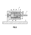
- figure 3 which represents in section one of these sensor means 4, a portion 31 of the touch interface 3 on which it is mounted and a part of the mounting bracket 5 on which the sensor is mounted. Subsequently, only one of these sensor means 4 will be described, it being understood that in the embodiment illustrated by the Figures 1 and 2 all sensor means 4 are identical.
- the sensor means 4 comprises a housing 41 comprising an orifice placed opposite an orifice of an extension of the mounting support 5, a fastening means such as a screw 7 being inserted into these orifices to fix the housing 41 to the mounting bracket 5.
- a slideway 42 is disposed in the housing 41.
- the peripheral portion 31 of the touch interface 3 is inserted into the slideway 42.
- This peripheral portion 31 has an upper boss 311 arranged to come into contact and deforming the upper wall of the slideway 42 and a lower projection 312 arranged to come into contact and deform the bottom wall of the slideway 42.
- the sensor means 4 comprises a lower sensor 43 disposed between the slideway and the bottom wall of the housing 41 and an upper sensor 44 disposed between the slideway and the top wall of the housing 41.
- Each of the lower 43 and upper 44 sensors comprises a flexible printed circuit 45 comprising detection means, for example of the capacitive or resistive type, deformation on the touch interface 3, the flexible printed circuit 45 being folded on itself and the foam 46 being inserted in the space between the two parts of the printed circuit 45.
- the structure of the sensor means 4, namely the deformable slide 42 and the foam 46 of the sensors 43 and 44, makes it possible to ensure that the sensors 43 and 44 are always in contact with the peripheral portion 31 and that movements of the tactile interface 3 in the direction z vis-a-vis the sensor means 4, and therefore the mounting bracket 5, are prohibited by the sensor means 4.
- the touch interface 3 is thus blocked in the z direction, that is to say the main direction of the deformations caused by the contacts, only a deformation related to a contact can give rise to a detection of a contact.
- the entire touch interface 3 is made of a transparent or translucent material so that the touch interface 3 comprises light output portions 3a, 3b, 3c and 3d, each of the output portions being associated with the light.
- one of the light sources respectively 2a, 2b, 2c and 2d so that light rays emitted by one of these light sources leave the device via its associated output portion.
- the upper mask 8 is arranged so as to surround the periphery of all the output portions 3a, 3b, 3c and 3d.
- the first set of light sources 2a comprises two light sources 2a each disposed between the mounting bracket 5 and the touch interface 3 at an output portion 3a of reduced shape compared to the extent of the touch interface.
- Each light source 2a is a light-emitting diode capable of emitting light of white color and is associated with a collimator 2a1 arranged to deflect the light rays emitted by this light source 2a towards a restricted predetermined zone of the passenger compartment so as to achieve a reading function.
- the controller of the device 1 is arranged so that upon detection of a contact on the touch interface at the output portion 3a, the controller generates an on / off command of the associated light source 2a so that this light source emits light if it is off or stops light emission if it is lit.
- the light source 2b is also disposed between the mounting bracket 5 and the touch interface 3 at a reduced-shaped output portion 3b compared to the extent of the touch interface 3.
- the light source 2b comprises a light-emitting diode capable of emitting ultraviolet radiation.
- the output portion 3b comprises photoluminescent patterns made of a fluorescent material capable of emitting white light when subjected to ultraviolet radiation. It is thus understood that the ultraviolet radiation emitted by the light source 2b will reach the photoluminescent patterns by causing the emission of white light for the realization of a reading function.
- the controller of the device 1 is arranged so that on detecting a contact on the touch interface at the output portion 3b, this controller generates an instruction for switching on or off the light source 2b so that this light source emits ultraviolet radiation if it is off or stops the emission of this radiation if it is on.
- the device comprises a lower mask 9 extending on the same dimensions as the tactile interface 3 and disposed between the light sources 2a and 2b and the touch interface 3.
- the lower mask 9 has orifices arranged vis-à-vis of the light source 2b and the collimators 2a1.
- Each light source 2a and 2b and the collimators 2a1 are mounted on a printed circuit fixed to the lower mask.
- the light sources 2c are light-emitting diodes able to emit light of white color and are arranged on the same printed circuit at one end 32 of the touch interface 3 so that light rays emitted by each of the these light sources 2c enter the touch interface.
- the touch interface is thus arranged as a light guide for guiding these light rays, via total internal reflection of these light rays on its internal walls, towards the output portion 3c.
- the touch interface 3 comprises decoupling prisms 3c1 arranged in band at the output portion 3c and oriented so that light rays emitted by the light sources 2c propagating in the touch interface 3 and reaching these means decoupling 3c1 out of the touch interface 3 by the output portion 3c.
- the controller of the device 1 is arranged so that a contact on the touch interface 3 at the output portion 3c triggers the emission of light of a predetermined luminous power by the light sources 2c for the realization of a diffuse lighting in the passenger compartment.
- This predetermined luminous power is a function of the distance separating the point of contact with the light sources 2c. For example, a contact on the touch interface on an area closest to the light sources 2c will trigger an extinction command of the light sources 2c and while a touch on the touch interface on a remote area of the light sources will trigger a ignition instruction of the light sources 2c for transmitting a maximum light output.
- the light sources 2d are light-emitting diodes of the RGB type capable of emitting selectively and / or together light of blue, red or green color. These light sources 2d are arranged on the same printed circuit board at one end 33 of the touch interface 3 so that light rays emitted by each of these light sources 2d enter the touch interface and are guided therethrough. to the output portion 3d.
- the touch interface 3 comprises 3d1 decoupling prisms arranged in band at the 3d output portion and oriented so that light rays emitted by the light sources 2d propagating in the touch interface 3 and reaching these means decoupling 3d1 out of the touch interface 3 by the output portion 3d.
- the decoupling prisms 3c1 and 3d1 are exclusively associated with the light sources respectively 2c and 2d, so that light rays emitted by one of these sources, for example 2c, and reaching prisms associated with the other of these sources. sources, for example 3d1, keep the same path without being deflected by these prisms towards the outside of the output portion, for example 3d.
- the invention is not limited to the only device according to the embodiment explicitly described with regard to the Figures 1 to 4d , or only to a specific application.
Landscapes
- Engineering & Computer Science (AREA)
- Mechanical Engineering (AREA)
- Arrangements Of Lighting Devices For Vehicle Interiors, Mounting And Supporting Thereof, Circuits Therefore (AREA)
Applications Claiming Priority (1)
| Application Number | Priority Date | Filing Date | Title |
|---|---|---|---|
| FR1459447A FR3026692B1 (fr) | 2014-10-02 | 2014-10-02 | Dispositif d'eclairage d'un habitacle de vehicule automobile |
Publications (3)
| Publication Number | Publication Date |
|---|---|
| EP3002155A2 true EP3002155A2 (de) | 2016-04-06 |
| EP3002155A3 EP3002155A3 (de) | 2016-10-05 |
| EP3002155B1 EP3002155B1 (de) | 2023-01-18 |
Family
ID=52358893
Family Applications (1)
| Application Number | Title | Priority Date | Filing Date |
|---|---|---|---|
| EP15187444.3A Active EP3002155B1 (de) | 2014-10-02 | 2015-09-29 | Beleuchtungsvorrichtung für einen innenraum eines kraftfahrzeugs |
Country Status (3)
| Country | Link |
|---|---|
| US (1) | US10124723B2 (de) |
| EP (1) | EP3002155B1 (de) |
| FR (1) | FR3026692B1 (de) |
Cited By (1)
| Publication number | Priority date | Publication date | Assignee | Title |
|---|---|---|---|---|
| WO2019042727A1 (de) * | 2017-08-30 | 2019-03-07 | Volkswagen Aktiengesellschaft | Beleuchtungssystem für einen fahrzeuginnenraum |
Families Citing this family (3)
| Publication number | Priority date | Publication date | Assignee | Title |
|---|---|---|---|---|
| DE102017205789B4 (de) * | 2017-04-05 | 2022-04-21 | Volkswagen Aktiengesellschaft | Innenraumleuchte für ein Kraftfahrzeug |
| FR3072447B1 (fr) * | 2017-10-13 | 2019-09-20 | Psa Automobiles Sa | Dispositif d’eclairage |
| JP6781211B2 (ja) * | 2018-08-22 | 2020-11-04 | 矢崎総業株式会社 | 車両用室内照明装置およびルーフモジュール |
Family Cites Families (11)
| Publication number | Priority date | Publication date | Assignee | Title |
|---|---|---|---|---|
| US6092917A (en) * | 1997-12-02 | 2000-07-25 | Lear Donnelly Overhead Systems Llc | Single lens, push-push, dual lamp assembly |
| JP2000344010A (ja) * | 1999-06-09 | 2000-12-12 | Teeantee:Kk | 車両用室内灯 |
| JP2002172977A (ja) * | 2000-12-05 | 2002-06-18 | Teeantee:Kk | 車両用室内灯 |
| US6799875B2 (en) * | 2002-09-20 | 2004-10-05 | Innotec Corporation | Vehicle interior light |
| JP4263638B2 (ja) * | 2004-02-19 | 2009-05-13 | 小島プレス工業株式会社 | レンズ押下型の照明装置 |
| JP2005289202A (ja) * | 2004-03-31 | 2005-10-20 | Honda Access Corp | 自動車の室内照明装置 |
| JP4395104B2 (ja) * | 2004-11-08 | 2010-01-06 | アルプス電気株式会社 | 照明装置 |
| JP4588624B2 (ja) * | 2005-12-20 | 2010-12-01 | 矢崎総業株式会社 | 車両用室内灯 |
| JP4220528B2 (ja) * | 2006-03-02 | 2009-02-04 | 小島プレス工業株式会社 | 車室内用照明装置 |
| US8330385B2 (en) * | 2010-02-15 | 2012-12-11 | Ford Global Technologies, Llc | Light bar |
| FR3010669B1 (fr) * | 2013-09-09 | 2016-11-04 | Valeo Vision | Ensemble structurel de vehicule automobile |
-
2014
- 2014-10-02 FR FR1459447A patent/FR3026692B1/fr not_active Expired - Fee Related
-
2015
- 2015-09-29 EP EP15187444.3A patent/EP3002155B1/de active Active
- 2015-09-30 US US14/870,370 patent/US10124723B2/en active Active
Non-Patent Citations (1)
| Title |
|---|
| None |
Cited By (1)
| Publication number | Priority date | Publication date | Assignee | Title |
|---|---|---|---|---|
| WO2019042727A1 (de) * | 2017-08-30 | 2019-03-07 | Volkswagen Aktiengesellschaft | Beleuchtungssystem für einen fahrzeuginnenraum |
Also Published As
| Publication number | Publication date |
|---|---|
| FR3026692A1 (fr) | 2016-04-08 |
| FR3026692B1 (fr) | 2017-12-01 |
| EP3002155B1 (de) | 2023-01-18 |
| US10124723B2 (en) | 2018-11-13 |
| US20160096470A1 (en) | 2016-04-07 |
| EP3002155A3 (de) | 2016-10-05 |
Similar Documents
| Publication | Publication Date | Title |
|---|---|---|
| EP0978084A1 (de) | Optoelektronisches bilderfassungsgerät, insbesondere für strichkodes | |
| EP3002155B1 (de) | Beleuchtungsvorrichtung für einen innenraum eines kraftfahrzeugs | |
| CN110618536B (zh) | 包括led和光栅的照明设备 | |
| EP2045923B1 (de) | Vorrichtung mit beleuchteter, auf dem kapazitiven Effekt beruhenden berührungsempfindlichen Taste und Steuertastatur, die eine solche Vorrichtung umfasst | |
| WO2005018283A1 (fr) | Element lumineux comportant au moins un substrat et un revetement emettant de la lumiere | |
| JP2019067521A (ja) | 車両用灯具 | |
| EP3381748B1 (de) | Innenbeleuchtungsmodul für kraftfahrzeug | |
| WO2016124718A1 (fr) | Module lumineux d'un véhicule compatible au trafic gauche et au trafic droit | |
| EP2996142A1 (de) | Halterung für leuchtquelle mit integriertem anschluss | |
| EP2824385B1 (de) | Vorrichtung mit einem Lichtleiter zur zweifarbigen Beleuchtung und/oder Signalisierung, insbesondere für Kraftfahrzeug | |
| EP3884206A1 (de) | Multifunktionales lichtmodul mit zwei flachen lichtleitern | |
| EP2651694B1 (de) | Blinklicht | |
| FR3058102A1 (fr) | Interface de commande capacitive et retroeclairee pour vehicule automobile | |
| JP6769135B2 (ja) | 車両用灯具、車両用灯具を備える車両用後方視認装置 | |
| KR20120008161A (ko) | 화장품 케이스 | |
| FR3010484A1 (fr) | Dispositif d'eclairage d'un habitacle de vehicule automobile | |
| EP0653768A1 (de) | Steuertastenfeld für elektrische oder elektronische Systeme, insbesondere Anti-Diebstahlsysteme für Kraftfahrzeuge | |
| WO2020126178A1 (fr) | Dispositif d'éclairage pour plafonnier de véhicule | |
| EP1590602A1 (de) | Beleuchtungsvorrichtung | |
| EP2845771A1 (de) | Struktureinheit eines Kraftfahrzeugs | |
| JP5830399B2 (ja) | ライセンスプレートランプ | |
| EP2938511A1 (de) | Steuerungsvorrichtung | |
| WO2012072254A1 (fr) | Dispositif de rangement pour vehicule automobile et dispositif optique de detection de l'ouverture d'un tel dispositif | |
| EP3367525B1 (de) | Elektronisches gerät wie eine türklingel | |
| FR3102917A1 (fr) | Système d’ouverture à effet lumineux et mallette porte-documents intégrant un tel système d’ouverture |
Legal Events
| Date | Code | Title | Description |
|---|---|---|---|
| PUAI | Public reference made under article 153(3) epc to a published international application that has entered the european phase |
Free format text: ORIGINAL CODE: 0009012 |
|
| AK | Designated contracting states |
Kind code of ref document: A2 Designated state(s): AL AT BE BG CH CY CZ DE DK EE ES FI FR GB GR HR HU IE IS IT LI LT LU LV MC MK MT NL NO PL PT RO RS SE SI SK SM TR |
|
| AX | Request for extension of the european patent |
Extension state: BA ME |
|
| RIC1 | Information provided on ipc code assigned before grant |
Ipc: B60Q 3/02 20060101AFI20160510BHEP |
|
| PUAL | Search report despatched |
Free format text: ORIGINAL CODE: 0009013 |
|
| AK | Designated contracting states |
Kind code of ref document: A3 Designated state(s): AL AT BE BG CH CY CZ DE DK EE ES FI FR GB GR HR HU IE IS IT LI LT LU LV MC MK MT NL NO PL PT RO RS SE SI SK SM TR |
|
| AX | Request for extension of the european patent |
Extension state: BA ME |
|
| RIC1 | Information provided on ipc code assigned before grant |
Ipc: B60Q 3/02 20060101AFI20160831BHEP |
|
| STAA | Information on the status of an ep patent application or granted ep patent |
Free format text: STATUS: REQUEST FOR EXAMINATION WAS MADE |
|
| 17P | Request for examination filed |
Effective date: 20170403 |
|
| RBV | Designated contracting states (corrected) |
Designated state(s): AL AT BE BG CH CY CZ DE DK EE ES FI FR GB GR HR HU IE IS IT LI LT LU LV MC MK MT NL NO PL PT RO RS SE SI SK SM TR |
|
| STAA | Information on the status of an ep patent application or granted ep patent |
Free format text: STATUS: EXAMINATION IS IN PROGRESS |
|
| 17Q | First examination report despatched |
Effective date: 20210504 |
|
| REG | Reference to a national code |
Ref country code: DE Ref legal event code: R079 Ref document number: 602015082312 Country of ref document: DE Free format text: PREVIOUS MAIN CLASS: B60Q0003020000 Ipc: B60Q0003640000 |
|
| RIC1 | Information provided on ipc code assigned before grant |
Ipc: B60Q 3/82 20170101ALI20220328BHEP Ipc: B60Q 3/64 20170101AFI20220328BHEP |
|
| GRAP | Despatch of communication of intention to grant a patent |
Free format text: ORIGINAL CODE: EPIDOSNIGR1 |
|
| STAA | Information on the status of an ep patent application or granted ep patent |
Free format text: STATUS: GRANT OF PATENT IS INTENDED |
|
| INTG | Intention to grant announced |
Effective date: 20220830 |
|
| GRAS | Grant fee paid |
Free format text: ORIGINAL CODE: EPIDOSNIGR3 |
|
| GRAA | (expected) grant |
Free format text: ORIGINAL CODE: 0009210 |
|
| STAA | Information on the status of an ep patent application or granted ep patent |
Free format text: STATUS: THE PATENT HAS BEEN GRANTED |
|
| AK | Designated contracting states |
Kind code of ref document: B1 Designated state(s): AL AT BE BG CH CY CZ DE DK EE ES FI FR GB GR HR HU IE IS IT LI LT LU LV MC MK MT NL NO PL PT RO RS SE SI SK SM TR |
|
| REG | Reference to a national code |
Ref country code: GB Ref legal event code: FG4D Free format text: NOT ENGLISH |
|
| REG | Reference to a national code |
Ref country code: DE Ref legal event code: R096 Ref document number: 602015082312 Country of ref document: DE |
|
| REG | Reference to a national code |
Ref country code: CH Ref legal event code: EP |
|
| REG | Reference to a national code |
Ref country code: AT Ref legal event code: REF Ref document number: 1544505 Country of ref document: AT Kind code of ref document: T Effective date: 20230215 Ref country code: IE Ref legal event code: FG4D Free format text: LANGUAGE OF EP DOCUMENT: FRENCH |
|
| REG | Reference to a national code |
Ref country code: LT Ref legal event code: MG9D |
|
| REG | Reference to a national code |
Ref country code: NL Ref legal event code: MP Effective date: 20230118 |
|
| REG | Reference to a national code |
Ref country code: AT Ref legal event code: MK05 Ref document number: 1544505 Country of ref document: AT Kind code of ref document: T Effective date: 20230118 |
|
| PG25 | Lapsed in a contracting state [announced via postgrant information from national office to epo] |
Ref country code: NL Free format text: LAPSE BECAUSE OF FAILURE TO SUBMIT A TRANSLATION OF THE DESCRIPTION OR TO PAY THE FEE WITHIN THE PRESCRIBED TIME-LIMIT Effective date: 20230118 |
|
| P01 | Opt-out of the competence of the unified patent court (upc) registered |
Effective date: 20230528 |
|
| PG25 | Lapsed in a contracting state [announced via postgrant information from national office to epo] |
Ref country code: RS Free format text: LAPSE BECAUSE OF FAILURE TO SUBMIT A TRANSLATION OF THE DESCRIPTION OR TO PAY THE FEE WITHIN THE PRESCRIBED TIME-LIMIT Effective date: 20230118 Ref country code: PT Free format text: LAPSE BECAUSE OF FAILURE TO SUBMIT A TRANSLATION OF THE DESCRIPTION OR TO PAY THE FEE WITHIN THE PRESCRIBED TIME-LIMIT Effective date: 20230518 Ref country code: NO Free format text: LAPSE BECAUSE OF FAILURE TO SUBMIT A TRANSLATION OF THE DESCRIPTION OR TO PAY THE FEE WITHIN THE PRESCRIBED TIME-LIMIT Effective date: 20230418 Ref country code: LV Free format text: LAPSE BECAUSE OF FAILURE TO SUBMIT A TRANSLATION OF THE DESCRIPTION OR TO PAY THE FEE WITHIN THE PRESCRIBED TIME-LIMIT Effective date: 20230118 Ref country code: LT Free format text: LAPSE BECAUSE OF FAILURE TO SUBMIT A TRANSLATION OF THE DESCRIPTION OR TO PAY THE FEE WITHIN THE PRESCRIBED TIME-LIMIT Effective date: 20230118 Ref country code: HR Free format text: LAPSE BECAUSE OF FAILURE TO SUBMIT A TRANSLATION OF THE DESCRIPTION OR TO PAY THE FEE WITHIN THE PRESCRIBED TIME-LIMIT Effective date: 20230118 Ref country code: ES Free format text: LAPSE BECAUSE OF FAILURE TO SUBMIT A TRANSLATION OF THE DESCRIPTION OR TO PAY THE FEE WITHIN THE PRESCRIBED TIME-LIMIT Effective date: 20230118 Ref country code: AT Free format text: LAPSE BECAUSE OF FAILURE TO SUBMIT A TRANSLATION OF THE DESCRIPTION OR TO PAY THE FEE WITHIN THE PRESCRIBED TIME-LIMIT Effective date: 20230118 |
|
| PG25 | Lapsed in a contracting state [announced via postgrant information from national office to epo] |
Ref country code: SE Free format text: LAPSE BECAUSE OF FAILURE TO SUBMIT A TRANSLATION OF THE DESCRIPTION OR TO PAY THE FEE WITHIN THE PRESCRIBED TIME-LIMIT Effective date: 20230118 Ref country code: PL Free format text: LAPSE BECAUSE OF FAILURE TO SUBMIT A TRANSLATION OF THE DESCRIPTION OR TO PAY THE FEE WITHIN THE PRESCRIBED TIME-LIMIT Effective date: 20230118 Ref country code: IS Free format text: LAPSE BECAUSE OF FAILURE TO SUBMIT A TRANSLATION OF THE DESCRIPTION OR TO PAY THE FEE WITHIN THE PRESCRIBED TIME-LIMIT Effective date: 20230518 Ref country code: GR Free format text: LAPSE BECAUSE OF FAILURE TO SUBMIT A TRANSLATION OF THE DESCRIPTION OR TO PAY THE FEE WITHIN THE PRESCRIBED TIME-LIMIT Effective date: 20230419 Ref country code: FI Free format text: LAPSE BECAUSE OF FAILURE TO SUBMIT A TRANSLATION OF THE DESCRIPTION OR TO PAY THE FEE WITHIN THE PRESCRIBED TIME-LIMIT Effective date: 20230118 |
|
| REG | Reference to a national code |
Ref country code: DE Ref legal event code: R097 Ref document number: 602015082312 Country of ref document: DE |
|
| PG25 | Lapsed in a contracting state [announced via postgrant information from national office to epo] |
Ref country code: SM Free format text: LAPSE BECAUSE OF FAILURE TO SUBMIT A TRANSLATION OF THE DESCRIPTION OR TO PAY THE FEE WITHIN THE PRESCRIBED TIME-LIMIT Effective date: 20230118 Ref country code: RO Free format text: LAPSE BECAUSE OF FAILURE TO SUBMIT A TRANSLATION OF THE DESCRIPTION OR TO PAY THE FEE WITHIN THE PRESCRIBED TIME-LIMIT Effective date: 20230118 Ref country code: EE Free format text: LAPSE BECAUSE OF FAILURE TO SUBMIT A TRANSLATION OF THE DESCRIPTION OR TO PAY THE FEE WITHIN THE PRESCRIBED TIME-LIMIT Effective date: 20230118 Ref country code: DK Free format text: LAPSE BECAUSE OF FAILURE TO SUBMIT A TRANSLATION OF THE DESCRIPTION OR TO PAY THE FEE WITHIN THE PRESCRIBED TIME-LIMIT Effective date: 20230118 Ref country code: CZ Free format text: LAPSE BECAUSE OF FAILURE TO SUBMIT A TRANSLATION OF THE DESCRIPTION OR TO PAY THE FEE WITHIN THE PRESCRIBED TIME-LIMIT Effective date: 20230118 |
|
| PLBE | No opposition filed within time limit |
Free format text: ORIGINAL CODE: 0009261 |
|
| STAA | Information on the status of an ep patent application or granted ep patent |
Free format text: STATUS: NO OPPOSITION FILED WITHIN TIME LIMIT |
|
| PG25 | Lapsed in a contracting state [announced via postgrant information from national office to epo] |
Ref country code: SK Free format text: LAPSE BECAUSE OF FAILURE TO SUBMIT A TRANSLATION OF THE DESCRIPTION OR TO PAY THE FEE WITHIN THE PRESCRIBED TIME-LIMIT Effective date: 20230118 |
|
| 26N | No opposition filed |
Effective date: 20231019 |
|
| PG25 | Lapsed in a contracting state [announced via postgrant information from national office to epo] |
Ref country code: SI Free format text: LAPSE BECAUSE OF FAILURE TO SUBMIT A TRANSLATION OF THE DESCRIPTION OR TO PAY THE FEE WITHIN THE PRESCRIBED TIME-LIMIT Effective date: 20230118 |
|
| REG | Reference to a national code |
Ref country code: CH Ref legal event code: PL |
|
| PG25 | Lapsed in a contracting state [announced via postgrant information from national office to epo] |
Ref country code: LU Free format text: LAPSE BECAUSE OF NON-PAYMENT OF DUE FEES Effective date: 20230929 |
|
| REG | Reference to a national code |
Ref country code: BE Ref legal event code: MM Effective date: 20230930 |
|
| GBPC | Gb: european patent ceased through non-payment of renewal fee |
Effective date: 20230929 |
|
| PG25 | Lapsed in a contracting state [announced via postgrant information from national office to epo] |
Ref country code: LU Free format text: LAPSE BECAUSE OF NON-PAYMENT OF DUE FEES Effective date: 20230929 Ref country code: IT Free format text: LAPSE BECAUSE OF FAILURE TO SUBMIT A TRANSLATION OF THE DESCRIPTION OR TO PAY THE FEE WITHIN THE PRESCRIBED TIME-LIMIT Effective date: 20230118 Ref country code: MC Free format text: LAPSE BECAUSE OF FAILURE TO SUBMIT A TRANSLATION OF THE DESCRIPTION OR TO PAY THE FEE WITHIN THE PRESCRIBED TIME-LIMIT Effective date: 20230118 |
|
| REG | Reference to a national code |
Ref country code: IE Ref legal event code: MM4A |
|
| PG25 | Lapsed in a contracting state [announced via postgrant information from national office to epo] |
Ref country code: IE Free format text: LAPSE BECAUSE OF NON-PAYMENT OF DUE FEES Effective date: 20230929 |
|
| PG25 | Lapsed in a contracting state [announced via postgrant information from national office to epo] |
Ref country code: GB Free format text: LAPSE BECAUSE OF NON-PAYMENT OF DUE FEES Effective date: 20230929 |
|
| PG25 | Lapsed in a contracting state [announced via postgrant information from national office to epo] |
Ref country code: CH Free format text: LAPSE BECAUSE OF NON-PAYMENT OF DUE FEES Effective date: 20230930 |
|
| PG25 | Lapsed in a contracting state [announced via postgrant information from national office to epo] |
Ref country code: IE Free format text: LAPSE BECAUSE OF NON-PAYMENT OF DUE FEES Effective date: 20230929 Ref country code: GB Free format text: LAPSE BECAUSE OF NON-PAYMENT OF DUE FEES Effective date: 20230929 Ref country code: CH Free format text: LAPSE BECAUSE OF NON-PAYMENT OF DUE FEES Effective date: 20230930 |
|
| PG25 | Lapsed in a contracting state [announced via postgrant information from national office to epo] |
Ref country code: BE Free format text: LAPSE BECAUSE OF NON-PAYMENT OF DUE FEES Effective date: 20230930 |
|
| PG25 | Lapsed in a contracting state [announced via postgrant information from national office to epo] |
Ref country code: BG Free format text: LAPSE BECAUSE OF FAILURE TO SUBMIT A TRANSLATION OF THE DESCRIPTION OR TO PAY THE FEE WITHIN THE PRESCRIBED TIME-LIMIT Effective date: 20230118 |
|
| PG25 | Lapsed in a contracting state [announced via postgrant information from national office to epo] |
Ref country code: BG Free format text: LAPSE BECAUSE OF FAILURE TO SUBMIT A TRANSLATION OF THE DESCRIPTION OR TO PAY THE FEE WITHIN THE PRESCRIBED TIME-LIMIT Effective date: 20230118 |
|
| PG25 | Lapsed in a contracting state [announced via postgrant information from national office to epo] |
Ref country code: CY Free format text: LAPSE BECAUSE OF FAILURE TO SUBMIT A TRANSLATION OF THE DESCRIPTION OR TO PAY THE FEE WITHIN THE PRESCRIBED TIME-LIMIT; INVALID AB INITIO Effective date: 20150929 |
|
| PG25 | Lapsed in a contracting state [announced via postgrant information from national office to epo] |
Ref country code: HU Free format text: LAPSE BECAUSE OF FAILURE TO SUBMIT A TRANSLATION OF THE DESCRIPTION OR TO PAY THE FEE WITHIN THE PRESCRIBED TIME-LIMIT; INVALID AB INITIO Effective date: 20150929 |
|
| PGFP | Annual fee paid to national office [announced via postgrant information from national office to epo] |
Ref country code: DE Payment date: 20250916 Year of fee payment: 11 |
|
| PGFP | Annual fee paid to national office [announced via postgrant information from national office to epo] |
Ref country code: FR Payment date: 20250929 Year of fee payment: 11 |
|
| PG25 | Lapsed in a contracting state [announced via postgrant information from national office to epo] |
Ref country code: TR Free format text: LAPSE BECAUSE OF FAILURE TO SUBMIT A TRANSLATION OF THE DESCRIPTION OR TO PAY THE FEE WITHIN THE PRESCRIBED TIME-LIMIT Effective date: 20230118 |