EP3006285A1 - Commutateur de type magnétique - Google Patents
Commutateur de type magnétique Download PDFInfo
- Publication number
- EP3006285A1 EP3006285A1 EP15185355.3A EP15185355A EP3006285A1 EP 3006285 A1 EP3006285 A1 EP 3006285A1 EP 15185355 A EP15185355 A EP 15185355A EP 3006285 A1 EP3006285 A1 EP 3006285A1
- Authority
- EP
- European Patent Office
- Prior art keywords
- magnetic
- magnet
- switch
- stay
- brake pedal
- Prior art date
- Legal status (The legal status is an assumption and is not a legal conclusion. Google has not performed a legal analysis and makes no representation as to the accuracy of the status listed.)
- Granted
Links
Images


Classifications
-
- H—ELECTRICITY
- H01—ELECTRIC ELEMENTS
- H01H—ELECTRIC SWITCHES; RELAYS; SELECTORS; EMERGENCY PROTECTIVE DEVICES
- H01H36/00—Switches actuated by change of magnetic field or of electric field, e.g. by change of relative position of magnet and switch, by shielding
- H01H36/02—Switches actuated by change of magnetic field or of electric field, e.g. by change of relative position of magnet and switch, by shielding actuated by movement of a float carrying a magnet
-
- H—ELECTRICITY
- H01—ELECTRIC ELEMENTS
- H01H—ELECTRIC SWITCHES; RELAYS; SELECTORS; EMERGENCY PROTECTIVE DEVICES
- H01H36/00—Switches actuated by change of magnetic field or of electric field, e.g. by change of relative position of magnet and switch, by shielding
- H01H36/0073—Switches actuated by change of magnetic field or of electric field, e.g. by change of relative position of magnet and switch, by shielding actuated by relative movement between two magnets
-
- B—PERFORMING OPERATIONS; TRANSPORTING
- B60—VEHICLES IN GENERAL
- B60T—VEHICLE BRAKE CONTROL SYSTEMS OR PARTS THEREOF; BRAKE CONTROL SYSTEMS OR PARTS THEREOF, IN GENERAL; ARRANGEMENT OF BRAKING ELEMENTS ON VEHICLES IN GENERAL; PORTABLE DEVICES FOR PREVENTING UNWANTED MOVEMENT OF VEHICLES; VEHICLE MODIFICATIONS TO FACILITATE COOLING OF BRAKES
- B60T17/00—Component parts, details, or accessories of power brake systems not covered by groups B60T8/00, B60T13/00 or B60T15/00, or presenting other characteristic features
- B60T17/18—Safety devices; Monitoring
- B60T17/22—Devices for monitoring or checking brake systems; Signal devices
-
- B—PERFORMING OPERATIONS; TRANSPORTING
- B60—VEHICLES IN GENERAL
- B60T—VEHICLE BRAKE CONTROL SYSTEMS OR PARTS THEREOF; BRAKE CONTROL SYSTEMS OR PARTS THEREOF, IN GENERAL; ARRANGEMENT OF BRAKING ELEMENTS ON VEHICLES IN GENERAL; PORTABLE DEVICES FOR PREVENTING UNWANTED MOVEMENT OF VEHICLES; VEHICLE MODIFICATIONS TO FACILITATE COOLING OF BRAKES
- B60T7/00—Brake-action initiating means
- B60T7/02—Brake-action initiating means for personal initiation
- B60T7/04—Brake-action initiating means for personal initiation foot actuated
- B60T7/06—Disposition of pedal
-
- H—ELECTRICITY
- H01—ELECTRIC ELEMENTS
- H01H—ELECTRIC SWITCHES; RELAYS; SELECTORS; EMERGENCY PROTECTIVE DEVICES
- H01H36/00—Switches actuated by change of magnetic field or of electric field, e.g. by change of relative position of magnet and switch, by shielding
-
- H—ELECTRICITY
- H01—ELECTRIC ELEMENTS
- H01H—ELECTRIC SWITCHES; RELAYS; SELECTORS; EMERGENCY PROTECTIVE DEVICES
- H01H36/00—Switches actuated by change of magnetic field or of electric field, e.g. by change of relative position of magnet and switch, by shielding
- H01H36/0006—Permanent magnet actuating reed switches
- H01H36/0013—Permanent magnet actuating reed switches characterised by the co-operation between reed switch and permanent magnet; Magnetic circuits
- H01H36/002—Actuation by moving ferromagnetic material, switch and magnet being fixed
-
- H—ELECTRICITY
- H01—ELECTRIC ELEMENTS
- H01H—ELECTRIC SWITCHES; RELAYS; SELECTORS; EMERGENCY PROTECTIVE DEVICES
- H01H9/00—Details of switching devices, not covered by groups H01H1/00 - H01H7/00
- H01H9/02—Bases, casings, or covers
-
- H—ELECTRICITY
- H03—ELECTRONIC CIRCUITRY
- H03K—PULSE TECHNIQUE
- H03K17/00—Electronic switching or gating, i.e. not by contact-making and –breaking
- H03K17/94—Electronic switching or gating, i.e. not by contact-making and –breaking characterised by the way in which the control signals are generated
- H03K17/965—Switches controlled by moving an element forming part of the switch
- H03K17/97—Switches controlled by moving an element forming part of the switch using a magnetic movable element
-
- B—PERFORMING OPERATIONS; TRANSPORTING
- B60—VEHICLES IN GENERAL
- B60Q—ARRANGEMENT OF SIGNALLING OR LIGHTING DEVICES, THE MOUNTING OR SUPPORTING THEREOF OR CIRCUITS THEREFOR, FOR VEHICLES IN GENERAL
- B60Q1/00—Arrangement of optical signalling or lighting devices, the mounting or supporting thereof or circuits therefor
- B60Q1/26—Arrangement of optical signalling or lighting devices, the mounting or supporting thereof or circuits therefor the devices being primarily intended to indicate the vehicle, or parts thereof, or to give signals, to other traffic
- B60Q1/44—Arrangement of optical signalling or lighting devices, the mounting or supporting thereof or circuits therefor the devices being primarily intended to indicate the vehicle, or parts thereof, or to give signals, to other traffic for indicating braking action or preparation for braking, e.g. by detection of the foot approaching the brake pedal
- B60Q1/441—Electric switches operable by the driver's pedals
Definitions
- the present invention relates to a magnetic type switch that detects a position of a detected element without contact therewith.
- a magnetic type switch is more superior in a point where there occurs no degradation in the switch due to contact with a detection object because of detecting a position of the detection object without contact therewith as compared to a conventional switch that detects a position of a detection object by making contact with the detection object, and there are various kinds of application examples of this magnetic type switch to various types of switches for vehicles (for example, refer to Japanese Patent Laid-Open Publication No. 2012-251809 )
- a magnetic type switch that detects an operation of a brake pedal is designed such that a magnet in the switch is provided to face a magnetic body attached to the brake pedal, and the magnetic type switch outputs an ON/OFF signal that indicates presence/absence of the operation of the brake pedal by detecting a change of magnetic field at the time a distance between the magnetic body and the magnet changes by the operation of the brake pedal.
- a switch that detects an operation of the brake pedal is also arranged under the driver's foot.
- the magnetic field by the magnet in the magnetic type switch is required to be not subjected to an influence by an external factor such as iron sand.
- the present invention is made in view of the aforementioned problem, and an object of the present invention is to provide a magnetic type switch in which magnetic field of a magnet is not subjected to an influence of an external factor.
- a magnetic type switch in which a magnetic pole face of a magnet is arranged to face a magnetic body provided in an object, and a change in magnetic field due to a change in distance between the magnetic body and the magnet by an operation of the object is detected to output a signal for indicating presence/absence of the operation of the object, characterized in that the magnetic pole face of the magnet is arranged to face the magnetic body to have a facing part to the magnetic body between the magnetic pole face and the magnetic body within a casing of having the facing part, and a protector member formed of a non-magnetic body having a predetermined thickness in a direction vertical to the magnetic pole face is attached to the casing to cover at least the facing part with the protector member.
- the protector member Since magnetic force lines extend in the vertical direction to the magnetic pole face, when the magnetic type switch is structured as described above, the protector member results in being positioned in a section where density of the magnetic force lines is the highest.
- the iron sand pulled in by the magnetic force of the magnet cannot be closer to the magnet than the protector member, and the pulled-in iron sand cannot be magnetized or even if it is magnetized, magnetic susceptibility thereof becomes low.
- the magnetic type switch of the present invention which is different from a case where the protector member is not provided, since the pulled-in iron sand does not achieve a function as a magnet to collect a great deal of iron sand in a chained manner, the magnetic field of the magnet in the magnetic type switch is not affected by the iron sand or the like.
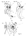
- Fig. 1A to Fig. 1C are diagrams each explaining an installation state of a magnetic type switch 1 that outputs a signal for indicating presence/absence of an operation of a brake pedal 2, wherein Fig. 1A is a perspective view illustrating the switch 1, Fig. 1B is a side view thereof and Fig. 1C is an enlarged view illustrating the surroundings thereof.
- Fig. 2A is a sectional view illustrating the surroundings of the switch 1
- Fig. 2B is a sectional view taken along line A-A in Fig. 2A and is a diagram illustrating an inner periphery 410 of a tubular part 41 in a clip 4 in a virtual line
- Fig. 2C is an enlarged view of Region B in Fig. 2A .
- a bracket 3 fixed on the vehicle body side has side plates 31a, 31b that are arranged in parallel to each other to be spaced therebetween in the width direction.
- the side plate 31a and the side plate 31b are provided with a shaft member 32 that penetrates therethrough, the shaft member 32 supporting a brake pedal 2 to be rotatable thereon.
- the brake pedal 2 is formed of a plate-shaped base part 21 one end 21a of which is rotatably supported by the shaft member 32, and an operating part 22 provided in the other end 21b that is capable of being displaced in the circumferential direction around a rotational axis X.
- the base part 21 is made of magnetic material, and a stay 23 formed in a square shape as viewed from the compartment inside is provided in a side edge 21c in the compartment inside closer to the one end 21a-side of the base part 21.
- the stay 23 is made of ferromagnetic material such as iron and extends from the side edge 21c of the base part 21 to the side plate 31b-side along the rotational axis X direction.
- a support plate part 33 of the switch 1 is provided in a position spaced from the stay 23 upward in the compartment inside.
- the support plate part 33 extends to the side plate 31b-side from a side edge, closer to the compartment inside, of the side plate 31a, and a tip 33a of the support plate part 33 is positioned closer to the side plate 31b than the stay 23.
- the support plate part 33 is provided with a through hole 33b that penetrates through the support plate part 33 in the thickness direction, and a clip 4 for attaching the switch 1 on the support plate part 33 is fitted in the through hole 33b for fixation.
- the clip 4 has a tubular part 41 that is inserted in the through hole 33b and a collar part 42 that surrounds one end of the tubular part 41 over an entire circumference.
- the clip 4 is structured such that when the tubular part 41 is inserted in the through hole 33b until the collar part 42 abuts on a face 33c, closer to the compartment inside, of the support plate part 33, an engaging part (unillustrated) provided on an outer periphery of the tubular part 41 makes pressure-contact with an inner periphery of the through hole 33b to prevent the clip 4 from dropping out of the support plate part 33.
- screw groove parts 410a that project to the tubular part 41-inside are provided on an inner periphery 410 of the tubular part 41, and are provided in two locations to be spaced in the circumferential direction in a sectional view.
- Screw grooves are provided along the circumferential direction on an inner periphery of the screw groove parts 410a, and at the time of supporting the switch 1 with the clip 4, meshing of screw parts 521 provided in a body casing 5 of the switch 1 with the screw grooves blocks the switch 1 from dropping out of the support plate part 33.
- the body casing 5 of the switch 1 is formed of a bottomed, tubular accommodation part 51 and an enclosing part 55 that closes an opening 51a of the accommodation part 51, and a print board 6 having a hall element 61 and a magnet holding member 8 in a tip of which a magnet 71 is insert-molded are accommodated in the body casing 5.
- the accommodation part 51 is formed of a tubular peripheral wall part 52 and a bottom wall part 53 that closes one end of the peripheral wall part 52 in the longitudinal direction, and the screw parts 521 meshing with the screw groove parts 410a of the aforementioned clip 4 are provided on the outer periphery of the peripheral wall part 52 in a position offset to the opening 51a-side from the bottom wall part 53 (refer to Fig. 2B ).
- an outer peripheral face 520 of the peripheral wall part 52 is formed in an arc shape along a virtual circle having a diameter D1 in a sectional view, and the screw parts 521 and projection parts 552 are provided alternately two by two on the outer peripheral face 520 to be spaced in the circumferential direction.
- the outer diameter D1 of a section of the peripheral wall part 52 in which the screw part 521 and the projection part 552 are not provided is made smaller than an inner diameter D3 of the tubular part 41 of the aforementioned clip 4, and an outer diameter D2 of a section of the peripheral wall part 52 in which the screw part 521 and the projection part 552 are provided is formed in a diameter substantially aligned to an inner diameter D3 of the tubular part 41.
- the accommodation part 51 of the switch 1 is designed to be capable of being inserted in the tubular part 41 of the clip 4 in a state where the screw groove part 410a and the screw part 521 in the circumferential direction around an axis line L of the peripheral wall part 52 are shifted in phase from each other.
- the accommodation part 51 is inserted into the tubular part 41 of the clip 4 to position the switch 1 in the axis line L direction, and thereafter, when the switch 1 (body casing 5) is rotated in the circumferential direction around the axis line L to mesh the screw part 521 with the screw groove part 410a, it prevents the switch 1 from dropping out of the support plate part 33 (clip 4) and from being shifted in position in the axis line L direction.
- the magnet holding member 8 is designed to be inserted in the accommodation part 51 of the body casing 5 from the opening 51a-side in an axial direction of the axis line L passing through a center of the peripheral wall part 52.
- the enclosing part 55 that closes the opening 51a of the accommodation part 51 has a tubular fitting wall 56 that is fitted in the peripheral wall part 52.
- the magnet holding member 8 inserted in the accommodation part 51 is pushed by the fitting wall 56 to hold a magnetic pole face 71a of the magnet 71 provided in the tip in a position close to the bottom wall part 53.
- the magnetic pole face 71a of the magnet 71 faces the bottom wall part 53 to be slightly spaced from the bottom wall part 53.
- a width W1 of the magnetic pole face 71a of the magnet 71 is made smaller than a width W4 of the bottom wall part 53, and a facing position of the magnetic pole face 71a to the bottom wall part 53 is in one side from the axis line L (left, oblique, upward side in Fig. 2C ).
- a first yoke 81 and a second yoke 82 that are insert-molded in the magnet holding member 8 are arranged to face with each other to be spaced from each other on an axis line Ln in parallel to the magnetic pole face 71a.
- the magnetic pole face 71a of the magnet 71 faces the bottom wall part 53 over its entire surface, and sections of magnetic lines M extending from the magnetic pole face 71a of the magnet 71, the sections being close to the magnetic pole face 71a, are aligned in a direction penetrating the bottom wall part 53 in the thickness direction (refer to Fig. 3A ).
- the magnet 71 has N pole in the bottom wall part 53-side and S pole in the enclosing part 55-side, wherein N pole is formed in a cubic shape having a predetermined width W1.
- S pole positioned in the enclosing part 55-side of N pole is formed in a cube to have a connecting part to N pole having a width W2 narrower than N pole, and in a cubic shape such that the width is narrower according to being away from N pole.
- the first yoke 81 in a square pillar shape is provided in parallel to the magnetic pole face 71a inside N pole , and one end part 81a of the first yoke 81 projects closer to the board 60 than the magnet 71, and faces a hall element 61 provided in the board 60.
- the second yoke 82 embedded in the magnet holding member 8 by insert-molding is provided in the board 60 at the opposite to the hall element 61, and the first yoke 81 and the second yoke 82 oppose with each other to have the hall element 61 therebetween.
- the second yoke 82 is provided in parallel to the axis line L passing through the center of the peripheral wall part 52, and is arranged such that an end face 82a of the second yoke 82 in the bottom wall part 53-side is flush with the magnetic pole face 71a of the magnet 71.
- the magnetic pole face 71a of the magnet 71 and the end face 82a of the second yoke 82 each face the bottom wall part 53 to be slightly spaced from the bottom wall part 53, and in this state, the magnetic pole face 71a of the magnet 71 and the end face 82a of the second yoke 82 are positioned in the axis line L direction.
- the stay 23 provided in the brake pedal 2 as described above is positioned in a position to be spaced from the bottom wall part 53 in a direction away from the magnet 71 along the axis line L.
- the stay 23 is positioned in the vicinity of the bottom wall part 53 of the body casing 5 at the non-operation of the brake pedal 2, and moves to a position away from the bottom wall part 53 at the operation of the brake pedal 2.
- Fig. 3A is a diagram explaining a magnetic circuit that is formed by the magnet 71 of the switch 1 in a case where the stay 23 is positioned in the vicinity of the magnetic pole face 71a of the magnet 71
- Fig. 3B is a diagram explaining a magnetic circuit that is formed by the magnet 71 in a case where the stay 23 is not positioned in the vicinity of the magnetic pole face 71a of the magnet 71.
- the stay 23 provided in the brake pedal 2 is positioned in the vicinity of the magnetic pole face 71a of the magnet 71, and in this state, the magnetic circuit as illustrated in Fig. 3A is formed.
- the magnetic flux advancing in a direction of being away from the magnetic pole face 71a of the magnet 71 mostly passes through the stay 23 and goes toward the second yoke 82. Then, the magnetic flux having entered into the second yoke 82 goes across the hall element 61 to be led into the first yoke 81, and after that, goes from N pole to S pole in the magnet 71.
- a passing direction of the magnetic flux in the hall element 61 at this time is set to be along a magnetic sensitive direction, and density of the magnetic flux detected by the hall element 61 becomes a large value.
- the switch 1 outputs a signal for indicating ON/OFF of the brake pedal 2 based upon the detected density of the magnetic flux.
- the magnetic circuit formed around the magnet 71 in the switch 1 changes depending upon whether or not the stay 23 is positioned in the vicinity of the magnetic pole face 71a of the magnet 71.
- a protector member 9 having cushion properties is attached on the bottom wall part 53-side of the body casing 5 in the switch 1.
- the protector member 9 is disposed in a range of being capable of covering both of areas (areas A1, A2) where the density of the magnetic flux is high when the stay 23 is positioned in the vicinity of the magnetic pole face 71a of the magnet 71 and an area (area A1) where the density of the magnetic flux is high when the stay 23 is not positioned in the vicinity of the magnetic pole face 71a of the magnet 71.
- the protector member 9 is designed to have a thickness Wa (refer to Fig. 2A ) for preventing the iron sand having reached to the protector member 9 from being magnetized to the extent of being capable of pulling in other magnetic materials.
- the protector member 9 is provided with a peripheral wall part 91 to be capable of covering not only the bottom wall part 53 but also an outer periphery of the peripheral wall part 52 in the bottom wall part 53-side.
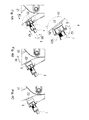
- Figs. 4A to 4C are diagrams explaining attachment of the switch 1 to the support plate part 33, wherein Fig. 4A is a diagram explaining a positional relation between the brake pedal 2 and the switch 1 for explaining the positioning of the switch 1 in the axis line L direction, Fig. 4B is a diagram indicating a positional relation between the stay 23 and the switch 1 when the brake pedal 2 is not operated, and Fig. 4C is a diagram indicating a positional relation between the stay 23 and the switch 1 when the brake pedal 2 is operated.
- the brake pedal 2 For positioning the switch 1 in the axis line L direction, the brake pedal 2 is rotated around the rotational axis X (refer to arrow A1 in Fig. 4A ) to be arranged in a positioning initial position set closer to the compartment inside than a reference position indicated in Fig. 4B .
- the accommodation part 51 of the switch 1 is inserted in the tubular part 41 of the clip 4 in a state where the screw part 521 (refer to Fig. 2B ) provided on the peripheral wall part 52 in the switch 1 and the screw groove part 410a (refer to Fig. 2B ) on the inner periphery of the tubular part 41 of the clip 4 are shifted in phase from each other around the axis line L (refer to arrow A2 in Fig. 4A ).
- the switch 1 is rotated around the axis line L to mesh the screw part 521 (refer to Fig. 2B ) provided on the peripheral wall part 52 in the switch 1 and the screw groove part 410a (refer to Fig. 2B ) on the inner periphery of the tubular part 41 of the clip 4 and restrict the movement of the switch 1 in the axis line L direction, thus positioning the switch 1 in the axis line L direction.
- the bottom wall part 53 is designed to press the body casing 5 covered with the protector member 9 against the stay 23.
- the protector member 9 is compressed between the stay 23 and the accommodation part 51 (body casing 5) at this positioning time, (1) when a compression amount of the protector member 9 varies, the switch 1 cannot be positioned with accuracy, and (2) after positioning the switch 1, when the shape of the protector member 9 is compressed and does not return back to the original, the iron sand pulled in by a magnetic force cannot be left away from the magnet 71. Therefore in the embodiment, the protector member 9 is made of a material that always has the same compression amount and has high resilience of the shape after the positioning.
- the protector member 9 a material that is a porous, non-magnetic material and has high resilience of the shape after the deformation, such as urethane foam, is used as the protector member 9.
- the brake pedal 2 is rotated around the rotational axis X in a direction of separating the stay 23 from the switch 1 (refer to arrow B1 in Fig. 4B ) by an urging force of an unillustrated spring to dispose the stay 23 in a predetermined position to have a gap d (refer to Fig. 2A ) from the protector member 9 attached to the switch 1.
- the object When the foreign object of the magnetic body such as iron sand is pulled in by the magnetic force to be attached on the magnet, the object is magnetized to achieve a function as the magnet. Then, different iron sand is pulled in to the magnetized iron sand and is attached thereto, and this attached different iron sand is also magnetized to achieve a function of the magnet. Therefore the pulled-in iron sands are magnetized in turn to be connected, and as a result, many iron sands get together in a chained manner and are lined up along magnetic force lines extending from the magnetic force face of the magnet.
- the protector member 9 made of the non-magnetic body having the predetermined thickness Wa in the direction vertical to the magnetic pole face 71a is provided on the bottom wall part 53, the iron sand pulled in by the magnetic force can be appropriately prevented from getting together in a chained manner along the magnetic force line of the magnet 71.
- the protector member 9 since the pulled-in iron sand does not achieve a function as a magnet so that many iron sands get together in a chained manner, the magnetic field of the magnet 71 in the magnetic type switch 1 is not affected by the iron sand.
- the protector member 9 Only by providing the protector member 9 on the bottom wall part 53 of the accommodation part 51 in the body casing 5, the attachment of the foreign object made of the magnetic body such as a magnet can be appropriately prevented. Therefore the attachment of the foreign object such as the iron sand on the body casing 5 in the switch 1 can be prevented without making the switch 1 large in size.
- the protector member 9 is formed of a sponge-shaped member that achieves cushion properties and is made of porous, flexibly deformable material, it is possible to appropriately prevent the weight of the switch 1 from increasing due to the prevention of the attachment of the foreign object such as the iron sand on the body casing 5 in the switch 1.
- the bake peal 2 returns back to the reference position by the urging force of the unillustrated spring.
- the stay 23 does not interfere with the protector member 9 while the brake pedal 2 returns back to the reference position.
- the iron sand (magnetic body) pulled in by the magnetic force can be magnetized to achieve a function as the magnet, not to prevent the pulled-in iron sand from getting together in a chained manner along the magnetic force line of the magnet 71.
Landscapes
- Engineering & Computer Science (AREA)
- Transportation (AREA)
- Mechanical Engineering (AREA)
- Switches That Are Operated By Magnetic Or Electric Fields (AREA)
- Push-Button Switches (AREA)
- Braking Elements And Transmission Devices (AREA)
- Rotary Switch, Piano Key Switch, And Lever Switch (AREA)
Applications Claiming Priority (1)
| Application Number | Priority Date | Filing Date | Title |
|---|---|---|---|
| JP2014207446A JP6434774B2 (ja) | 2014-10-08 | 2014-10-08 | スイッチ |
Publications (2)
| Publication Number | Publication Date |
|---|---|
| EP3006285A1 true EP3006285A1 (fr) | 2016-04-13 |
| EP3006285B1 EP3006285B1 (fr) | 2020-10-28 |
Family
ID=54147068
Family Applications (1)
| Application Number | Title | Priority Date | Filing Date |
|---|---|---|---|
| EP15185355.3A Active EP3006285B1 (fr) | 2014-10-08 | 2015-09-15 | Commutateur de type magnétique |
Country Status (5)
| Country | Link |
|---|---|
| US (1) | US9997315B2 (fr) |
| EP (1) | EP3006285B1 (fr) |
| JP (1) | JP6434774B2 (fr) |
| KR (1) | KR20160041763A (fr) |
| CN (1) | CN105513893B (fr) |
Families Citing this family (4)
| Publication number | Priority date | Publication date | Assignee | Title |
|---|---|---|---|---|
| US20190061725A1 (en) * | 2017-08-31 | 2019-02-28 | Nissan North America, Inc. | Parking Brake Cable Stretch Assist Tool |
| JP7132064B2 (ja) * | 2018-10-02 | 2022-09-06 | 株式会社ヴァレオジャパン | スイッチ装置 |
| US11657992B2 (en) | 2019-05-06 | 2023-05-23 | Jeffrey A. Stallmer | Protective cover assembly for magnetically actuating an electrical wall switch |
| JP7414050B2 (ja) * | 2021-09-07 | 2024-01-16 | カシオ計算機株式会社 | 押釦装置、時計および電子機器 |
Citations (6)
| Publication number | Priority date | Publication date | Assignee | Title |
|---|---|---|---|---|
| DE2011161A1 (de) * | 1970-03-10 | 1971-09-23 | Nix H | Magnetischer Schalter |
| US4316145A (en) * | 1976-10-01 | 1982-02-16 | Electro-Mechanical Products | Fluid pressure actuator with proximity position sensor |
| WO1987006656A1 (fr) * | 1986-04-29 | 1987-11-05 | Niels Hvilsted | Cylindre hydraulique avec piston et avec dispositif magnetique servant a determiner la position du piston |
| US6617845B1 (en) * | 2000-04-28 | 2003-09-09 | Rockwell Automation Technologies, Inc. | Proximity sensor resistant to environmental effects |
| FR2848936A1 (fr) * | 2002-12-20 | 2004-06-25 | Bosch Gmbh Robert | Maitre-cylindre comportant un dispositif de detection d'actionnement d'un systeme de freinage et vehicule comportant un tel maitre-cylindre |
| JP2012251809A (ja) | 2011-06-01 | 2012-12-20 | Honda Motor Co Ltd | 磁気式回転角検出装置及びブレーキバイワイヤ型制動制御装置 |
Family Cites Families (7)
| Publication number | Priority date | Publication date | Assignee | Title |
|---|---|---|---|---|
| JPS58154543U (ja) * | 1982-04-09 | 1983-10-15 | 株式会社山武 | 近接スイツチ |
| US5877664A (en) * | 1996-05-08 | 1999-03-02 | Jackson, Jr.; John T. | Magnetic proximity switch system |
| US7936242B2 (en) * | 2007-09-14 | 2011-05-03 | William N Carpenter | Magnetically operated electrical switch |
| US9329057B2 (en) * | 2012-05-31 | 2016-05-03 | Allegro Microsystems, Llc | Gear tooth sensor with peak and threshold detectors |
| JP5958314B2 (ja) * | 2012-12-06 | 2016-07-27 | トヨタ自動車株式会社 | スイッチ装置 |
| JP2014160640A (ja) * | 2013-01-28 | 2014-09-04 | Panasonic Corp | 保持部材及びこれを用いたスイッチ装置 |
| US9355800B2 (en) * | 2013-09-13 | 2016-05-31 | Cooper Technologies Company | Magnetic control devices for enclosures |
-
2014
- 2014-10-08 JP JP2014207446A patent/JP6434774B2/ja active Active
-
2015
- 2015-09-15 EP EP15185355.3A patent/EP3006285B1/fr active Active
- 2015-09-23 KR KR1020150134296A patent/KR20160041763A/ko not_active Abandoned
- 2015-09-28 CN CN201510626777.3A patent/CN105513893B/zh active Active
- 2015-10-07 US US14/877,608 patent/US9997315B2/en active Active
Patent Citations (6)
| Publication number | Priority date | Publication date | Assignee | Title |
|---|---|---|---|---|
| DE2011161A1 (de) * | 1970-03-10 | 1971-09-23 | Nix H | Magnetischer Schalter |
| US4316145A (en) * | 1976-10-01 | 1982-02-16 | Electro-Mechanical Products | Fluid pressure actuator with proximity position sensor |
| WO1987006656A1 (fr) * | 1986-04-29 | 1987-11-05 | Niels Hvilsted | Cylindre hydraulique avec piston et avec dispositif magnetique servant a determiner la position du piston |
| US6617845B1 (en) * | 2000-04-28 | 2003-09-09 | Rockwell Automation Technologies, Inc. | Proximity sensor resistant to environmental effects |
| FR2848936A1 (fr) * | 2002-12-20 | 2004-06-25 | Bosch Gmbh Robert | Maitre-cylindre comportant un dispositif de detection d'actionnement d'un systeme de freinage et vehicule comportant un tel maitre-cylindre |
| JP2012251809A (ja) | 2011-06-01 | 2012-12-20 | Honda Motor Co Ltd | 磁気式回転角検出装置及びブレーキバイワイヤ型制動制御装置 |
Also Published As
| Publication number | Publication date |
|---|---|
| US20160181035A1 (en) | 2016-06-23 |
| EP3006285B1 (fr) | 2020-10-28 |
| US9997315B2 (en) | 2018-06-12 |
| KR20160041763A (ko) | 2016-04-18 |
| JP2016076446A (ja) | 2016-05-12 |
| JP6434774B2 (ja) | 2018-12-05 |
| CN105513893A (zh) | 2016-04-20 |
| CN105513893B (zh) | 2020-08-11 |
Similar Documents
| Publication | Publication Date | Title |
|---|---|---|
| EP3006285A1 (fr) | Commutateur de type magnétique | |
| JP4560044B2 (ja) | 旋回角度センサを備えたボールジョイント | |
| CN104179955A (zh) | 换档装置 | |
| US9310392B2 (en) | Wheel-speed sensor mounting device | |
| EP1813925B1 (fr) | Détecteur de couple | |
| US11101718B2 (en) | Motor rotation detection device | |
| CN102224402B (zh) | 转向系统中扭矩测量用的传感装置及相应的转向系统 | |
| CN109891186B (zh) | 集成式双旋转位置传感器 | |
| CN107076574A (zh) | 用于确定电动机的转子位置的传感器单元和优选用于机动车的离合器操作系统的离合器执行装置的电动机 | |
| EP3129792B1 (fr) | Capteur de vitesse de roue | |
| US20140320113A1 (en) | Sensor | |
| JP2007212198A (ja) | トルク検出装置及びこれの製造方法 | |
| JP5510753B2 (ja) | アクセル装置 | |
| EP3620754B1 (fr) | Support d'aimant et capteur de course avec le support d'aimant | |
| US20200271219A1 (en) | Shift device | |
| JP2020118599A (ja) | センサ装置 | |
| US11578994B2 (en) | Fixing structure | |
| EP3516759B1 (fr) | Capteur de position rotatif à agencement de double aimant | |
| US7353618B2 (en) | Magnetic scale | |
| EP3312564B1 (fr) | Dispositif de détection d'angle de rotation et détecteur d'angle utilisé en son sein | |
| JP3489074B2 (ja) | ソレノイド | |
| KR20210150404A (ko) | 자기 측정 장치용 센서 | |
| JP4249758B2 (ja) | 回転角検出装置 | |
| JP7240595B2 (ja) | 移動体検出装置、及び移動体検出装置の製造方法 | |
| JP2009276241A (ja) | 回転角検出装置 |
Legal Events
| Date | Code | Title | Description |
|---|---|---|---|
| PUAI | Public reference made under article 153(3) epc to a published international application that has entered the european phase |
Free format text: ORIGINAL CODE: 0009012 |
|
| AK | Designated contracting states |
Kind code of ref document: A1 Designated state(s): AL AT BE BG CH CY CZ DE DK EE ES FI FR GB GR HR HU IE IS IT LI LT LU LV MC MK MT NL NO PL PT RO RS SE SI SK SM TR |
|
| AX | Request for extension of the european patent |
Extension state: BA ME |
|
| 17P | Request for examination filed |
Effective date: 20161012 |
|
| RBV | Designated contracting states (corrected) |
Designated state(s): AL AT BE BG CH CY CZ DE DK EE ES FI FR GB GR HR HU IE IS IT LI LT LU LV MC MK MT NL NO PL PT RO RS SE SI SK SM TR |
|
| GRAP | Despatch of communication of intention to grant a patent |
Free format text: ORIGINAL CODE: EPIDOSNIGR1 |
|
| STAA | Information on the status of an ep patent application or granted ep patent |
Free format text: STATUS: GRANT OF PATENT IS INTENDED |
|
| INTG | Intention to grant announced |
Effective date: 20200604 |
|
| GRAS | Grant fee paid |
Free format text: ORIGINAL CODE: EPIDOSNIGR3 |
|
| GRAA | (expected) grant |
Free format text: ORIGINAL CODE: 0009210 |
|
| STAA | Information on the status of an ep patent application or granted ep patent |
Free format text: STATUS: THE PATENT HAS BEEN GRANTED |
|
| AK | Designated contracting states |
Kind code of ref document: B1 Designated state(s): AL AT BE BG CH CY CZ DE DK EE ES FI FR GB GR HR HU IE IS IT LI LT LU LV MC MK MT NL NO PL PT RO RS SE SI SK SM TR |
|
| REG | Reference to a national code |
Ref country code: GB Ref legal event code: FG4D |
|
| REG | Reference to a national code |
Ref country code: CH Ref legal event code: EP |
|
| REG | Reference to a national code |
Ref country code: AT Ref legal event code: REF Ref document number: 1327919 Country of ref document: AT Kind code of ref document: T Effective date: 20201115 |
|
| REG | Reference to a national code |
Ref country code: DE Ref legal event code: R096 Ref document number: 602015061048 Country of ref document: DE |
|
| REG | Reference to a national code |
Ref country code: IE Ref legal event code: FG4D |
|
| REG | Reference to a national code |
Ref country code: AT Ref legal event code: MK05 Ref document number: 1327919 Country of ref document: AT Kind code of ref document: T Effective date: 20201028 |
|
| REG | Reference to a national code |
Ref country code: NL Ref legal event code: MP Effective date: 20201028 |
|
| PG25 | Lapsed in a contracting state [announced via postgrant information from national office to epo] |
Ref country code: GR Free format text: LAPSE BECAUSE OF FAILURE TO SUBMIT A TRANSLATION OF THE DESCRIPTION OR TO PAY THE FEE WITHIN THE PRESCRIBED TIME-LIMIT Effective date: 20210129 Ref country code: RS Free format text: LAPSE BECAUSE OF FAILURE TO SUBMIT A TRANSLATION OF THE DESCRIPTION OR TO PAY THE FEE WITHIN THE PRESCRIBED TIME-LIMIT Effective date: 20201028 Ref country code: FI Free format text: LAPSE BECAUSE OF FAILURE TO SUBMIT A TRANSLATION OF THE DESCRIPTION OR TO PAY THE FEE WITHIN THE PRESCRIBED TIME-LIMIT Effective date: 20201028 Ref country code: PT Free format text: LAPSE BECAUSE OF FAILURE TO SUBMIT A TRANSLATION OF THE DESCRIPTION OR TO PAY THE FEE WITHIN THE PRESCRIBED TIME-LIMIT Effective date: 20210301 Ref country code: NO Free format text: LAPSE BECAUSE OF FAILURE TO SUBMIT A TRANSLATION OF THE DESCRIPTION OR TO PAY THE FEE WITHIN THE PRESCRIBED TIME-LIMIT Effective date: 20210128 Ref country code: NL Free format text: LAPSE BECAUSE OF FAILURE TO SUBMIT A TRANSLATION OF THE DESCRIPTION OR TO PAY THE FEE WITHIN THE PRESCRIBED TIME-LIMIT Effective date: 20201028 |
|
| REG | Reference to a national code |
Ref country code: LT Ref legal event code: MG4D |
|
| PG25 | Lapsed in a contracting state [announced via postgrant information from national office to epo] |
Ref country code: AT Free format text: LAPSE BECAUSE OF FAILURE TO SUBMIT A TRANSLATION OF THE DESCRIPTION OR TO PAY THE FEE WITHIN THE PRESCRIBED TIME-LIMIT Effective date: 20201028 Ref country code: ES Free format text: LAPSE BECAUSE OF FAILURE TO SUBMIT A TRANSLATION OF THE DESCRIPTION OR TO PAY THE FEE WITHIN THE PRESCRIBED TIME-LIMIT Effective date: 20201028 Ref country code: BG Free format text: LAPSE BECAUSE OF FAILURE TO SUBMIT A TRANSLATION OF THE DESCRIPTION OR TO PAY THE FEE WITHIN THE PRESCRIBED TIME-LIMIT Effective date: 20210128 Ref country code: SE Free format text: LAPSE BECAUSE OF FAILURE TO SUBMIT A TRANSLATION OF THE DESCRIPTION OR TO PAY THE FEE WITHIN THE PRESCRIBED TIME-LIMIT Effective date: 20201028 Ref country code: LV Free format text: LAPSE BECAUSE OF FAILURE TO SUBMIT A TRANSLATION OF THE DESCRIPTION OR TO PAY THE FEE WITHIN THE PRESCRIBED TIME-LIMIT Effective date: 20201028 Ref country code: IS Free format text: LAPSE BECAUSE OF FAILURE TO SUBMIT A TRANSLATION OF THE DESCRIPTION OR TO PAY THE FEE WITHIN THE PRESCRIBED TIME-LIMIT Effective date: 20210228 Ref country code: PL Free format text: LAPSE BECAUSE OF FAILURE TO SUBMIT A TRANSLATION OF THE DESCRIPTION OR TO PAY THE FEE WITHIN THE PRESCRIBED TIME-LIMIT Effective date: 20201028 |
|
| PG25 | Lapsed in a contracting state [announced via postgrant information from national office to epo] |
Ref country code: HR Free format text: LAPSE BECAUSE OF FAILURE TO SUBMIT A TRANSLATION OF THE DESCRIPTION OR TO PAY THE FEE WITHIN THE PRESCRIBED TIME-LIMIT Effective date: 20201028 |
|
| REG | Reference to a national code |
Ref country code: DE Ref legal event code: R097 Ref document number: 602015061048 Country of ref document: DE |
|
| PG25 | Lapsed in a contracting state [announced via postgrant information from national office to epo] |
Ref country code: SK Free format text: LAPSE BECAUSE OF FAILURE TO SUBMIT A TRANSLATION OF THE DESCRIPTION OR TO PAY THE FEE WITHIN THE PRESCRIBED TIME-LIMIT Effective date: 20201028 Ref country code: RO Free format text: LAPSE BECAUSE OF FAILURE TO SUBMIT A TRANSLATION OF THE DESCRIPTION OR TO PAY THE FEE WITHIN THE PRESCRIBED TIME-LIMIT Effective date: 20201028 Ref country code: LT Free format text: LAPSE BECAUSE OF FAILURE TO SUBMIT A TRANSLATION OF THE DESCRIPTION OR TO PAY THE FEE WITHIN THE PRESCRIBED TIME-LIMIT Effective date: 20201028 Ref country code: SM Free format text: LAPSE BECAUSE OF FAILURE TO SUBMIT A TRANSLATION OF THE DESCRIPTION OR TO PAY THE FEE WITHIN THE PRESCRIBED TIME-LIMIT Effective date: 20201028 Ref country code: EE Free format text: LAPSE BECAUSE OF FAILURE TO SUBMIT A TRANSLATION OF THE DESCRIPTION OR TO PAY THE FEE WITHIN THE PRESCRIBED TIME-LIMIT Effective date: 20201028 Ref country code: CZ Free format text: LAPSE BECAUSE OF FAILURE TO SUBMIT A TRANSLATION OF THE DESCRIPTION OR TO PAY THE FEE WITHIN THE PRESCRIBED TIME-LIMIT Effective date: 20201028 |
|
| PG25 | Lapsed in a contracting state [announced via postgrant information from national office to epo] |
Ref country code: DK Free format text: LAPSE BECAUSE OF FAILURE TO SUBMIT A TRANSLATION OF THE DESCRIPTION OR TO PAY THE FEE WITHIN THE PRESCRIBED TIME-LIMIT Effective date: 20201028 |
|
| PLBE | No opposition filed within time limit |
Free format text: ORIGINAL CODE: 0009261 |
|
| STAA | Information on the status of an ep patent application or granted ep patent |
Free format text: STATUS: NO OPPOSITION FILED WITHIN TIME LIMIT |
|
| 26N | No opposition filed |
Effective date: 20210729 |
|
| PG25 | Lapsed in a contracting state [announced via postgrant information from national office to epo] |
Ref country code: IT Free format text: LAPSE BECAUSE OF FAILURE TO SUBMIT A TRANSLATION OF THE DESCRIPTION OR TO PAY THE FEE WITHIN THE PRESCRIBED TIME-LIMIT Effective date: 20201028 Ref country code: AL Free format text: LAPSE BECAUSE OF FAILURE TO SUBMIT A TRANSLATION OF THE DESCRIPTION OR TO PAY THE FEE WITHIN THE PRESCRIBED TIME-LIMIT Effective date: 20201028 |
|
| PG25 | Lapsed in a contracting state [announced via postgrant information from national office to epo] |
Ref country code: SI Free format text: LAPSE BECAUSE OF FAILURE TO SUBMIT A TRANSLATION OF THE DESCRIPTION OR TO PAY THE FEE WITHIN THE PRESCRIBED TIME-LIMIT Effective date: 20201028 |
|
| REG | Reference to a national code |
Ref country code: CH Ref legal event code: PL |
|
| REG | Reference to a national code |
Ref country code: BE Ref legal event code: MM Effective date: 20210930 |
|
| GBPC | Gb: european patent ceased through non-payment of renewal fee |
Effective date: 20210915 |
|
| PG25 | Lapsed in a contracting state [announced via postgrant information from national office to epo] |
Ref country code: IS Free format text: LAPSE BECAUSE OF FAILURE TO SUBMIT A TRANSLATION OF THE DESCRIPTION OR TO PAY THE FEE WITHIN THE PRESCRIBED TIME-LIMIT Effective date: 20210228 Ref country code: MC Free format text: LAPSE BECAUSE OF FAILURE TO SUBMIT A TRANSLATION OF THE DESCRIPTION OR TO PAY THE FEE WITHIN THE PRESCRIBED TIME-LIMIT Effective date: 20201028 |
|
| PG25 | Lapsed in a contracting state [announced via postgrant information from national office to epo] |
Ref country code: LU Free format text: LAPSE BECAUSE OF NON-PAYMENT OF DUE FEES Effective date: 20210915 Ref country code: IE Free format text: LAPSE BECAUSE OF NON-PAYMENT OF DUE FEES Effective date: 20210915 Ref country code: GB Free format text: LAPSE BECAUSE OF NON-PAYMENT OF DUE FEES Effective date: 20210915 Ref country code: BE Free format text: LAPSE BECAUSE OF NON-PAYMENT OF DUE FEES Effective date: 20210930 |
|
| PG25 | Lapsed in a contracting state [announced via postgrant information from national office to epo] |
Ref country code: LI Free format text: LAPSE BECAUSE OF NON-PAYMENT OF DUE FEES Effective date: 20210930 Ref country code: CH Free format text: LAPSE BECAUSE OF NON-PAYMENT OF DUE FEES Effective date: 20210930 |
|
| PG25 | Lapsed in a contracting state [announced via postgrant information from national office to epo] |
Ref country code: HU Free format text: LAPSE BECAUSE OF FAILURE TO SUBMIT A TRANSLATION OF THE DESCRIPTION OR TO PAY THE FEE WITHIN THE PRESCRIBED TIME-LIMIT; INVALID AB INITIO Effective date: 20150915 |
|
| PG25 | Lapsed in a contracting state [announced via postgrant information from national office to epo] |
Ref country code: CY Free format text: LAPSE BECAUSE OF FAILURE TO SUBMIT A TRANSLATION OF THE DESCRIPTION OR TO PAY THE FEE WITHIN THE PRESCRIBED TIME-LIMIT Effective date: 20201028 |
|
| PG25 | Lapsed in a contracting state [announced via postgrant information from national office to epo] |
Ref country code: MK Free format text: LAPSE BECAUSE OF FAILURE TO SUBMIT A TRANSLATION OF THE DESCRIPTION OR TO PAY THE FEE WITHIN THE PRESCRIBED TIME-LIMIT Effective date: 20201028 |
|
| PG25 | Lapsed in a contracting state [announced via postgrant information from national office to epo] |
Ref country code: TR Free format text: LAPSE BECAUSE OF FAILURE TO SUBMIT A TRANSLATION OF THE DESCRIPTION OR TO PAY THE FEE WITHIN THE PRESCRIBED TIME-LIMIT Effective date: 20201028 |
|
| PG25 | Lapsed in a contracting state [announced via postgrant information from national office to epo] |
Ref country code: MT Free format text: LAPSE BECAUSE OF FAILURE TO SUBMIT A TRANSLATION OF THE DESCRIPTION OR TO PAY THE FEE WITHIN THE PRESCRIBED TIME-LIMIT Effective date: 20201028 |
|
| PGFP | Annual fee paid to national office [announced via postgrant information from national office to epo] |
Ref country code: DE Payment date: 20250916 Year of fee payment: 11 |
|
| PGFP | Annual fee paid to national office [announced via postgrant information from national office to epo] |
Ref country code: FR Payment date: 20250929 Year of fee payment: 11 |