EP3129792B1 - Capteur de vitesse de roue - Google Patents
Capteur de vitesse de roue Download PDFInfo
- Publication number
- EP3129792B1 EP3129792B1 EP15702359.9A EP15702359A EP3129792B1 EP 3129792 B1 EP3129792 B1 EP 3129792B1 EP 15702359 A EP15702359 A EP 15702359A EP 3129792 B1 EP3129792 B1 EP 3129792B1
- Authority
- EP
- European Patent Office
- Prior art keywords
- electromagnetic sensor
- flange
- tone ring
- wheel speed
- wheel
- Prior art date
- Legal status (The legal status is an assumption and is not a legal conclusion. Google has not performed a legal analysis and makes no representation as to the accuracy of the status listed.)
- Active
Links
Images





Classifications
-
- G—PHYSICS
- G01—MEASURING; TESTING
- G01P—MEASURING LINEAR OR ANGULAR SPEED, ACCELERATION, DECELERATION, OR SHOCK; INDICATING PRESENCE, ABSENCE, OR DIRECTION, OF MOVEMENT
- G01P3/00—Measuring linear or angular speed; Measuring differences of linear or angular speeds
- G01P3/42—Devices characterised by the use of electric or magnetic means
- G01P3/44—Devices characterised by the use of electric or magnetic means for measuring angular speed
- G01P3/48—Devices characterised by the use of electric or magnetic means for measuring angular speed by measuring frequency of generated current or voltage
- G01P3/481—Devices characterised by the use of electric or magnetic means for measuring angular speed by measuring frequency of generated current or voltage of pulse signals
- G01P3/488—Devices characterised by the use of electric or magnetic means for measuring angular speed by measuring frequency of generated current or voltage of pulse signals delivered by variable reluctance detectors
-
- G—PHYSICS
- G01—MEASURING; TESTING
- G01P—MEASURING LINEAR OR ANGULAR SPEED, ACCELERATION, DECELERATION, OR SHOCK; INDICATING PRESENCE, ABSENCE, OR DIRECTION, OF MOVEMENT
- G01P3/00—Measuring linear or angular speed; Measuring differences of linear or angular speeds
- G01P3/42—Devices characterised by the use of electric or magnetic means
- G01P3/44—Devices characterised by the use of electric or magnetic means for measuring angular speed
-
- G—PHYSICS
- G01—MEASURING; TESTING
- G01D—MEASURING NOT SPECIALLY ADAPTED FOR A SPECIFIC VARIABLE; ARRANGEMENTS FOR MEASURING TWO OR MORE VARIABLES NOT COVERED IN A SINGLE OTHER SUBCLASS; TARIFF METERING APPARATUS; MEASURING OR TESTING NOT OTHERWISE PROVIDED FOR
- G01D5/00—Mechanical means for transferring the output of a sensing member; Means for converting the output of a sensing member to another variable where the form or nature of the sensing member does not constrain the means for converting; Transducers not specially adapted for a specific variable
- G01D5/12—Mechanical means for transferring the output of a sensing member; Means for converting the output of a sensing member to another variable where the form or nature of the sensing member does not constrain the means for converting; Transducers not specially adapted for a specific variable using electric or magnetic means
- G01D5/14—Mechanical means for transferring the output of a sensing member; Means for converting the output of a sensing member to another variable where the form or nature of the sensing member does not constrain the means for converting; Transducers not specially adapted for a specific variable using electric or magnetic means influencing the magnitude of a current or voltage
- G01D5/142—Mechanical means for transferring the output of a sensing member; Means for converting the output of a sensing member to another variable where the form or nature of the sensing member does not constrain the means for converting; Transducers not specially adapted for a specific variable using electric or magnetic means influencing the magnitude of a current or voltage using Hall-effect devices
- G01D5/145—Mechanical means for transferring the output of a sensing member; Means for converting the output of a sensing member to another variable where the form or nature of the sensing member does not constrain the means for converting; Transducers not specially adapted for a specific variable using electric or magnetic means influencing the magnitude of a current or voltage using Hall-effect devices influenced by the relative movement between the Hall device and magnetic fields
-
- G—PHYSICS
- G01—MEASURING; TESTING
- G01P—MEASURING LINEAR OR ANGULAR SPEED, ACCELERATION, DECELERATION, OR SHOCK; INDICATING PRESENCE, ABSENCE, OR DIRECTION, OF MOVEMENT
- G01P1/00—Details of instruments
- G01P1/02—Housings
- G01P1/026—Housings for speed measuring devices, e.g. pulse generator
-
- H—ELECTRICITY
- H02—GENERATION; CONVERSION OR DISTRIBUTION OF ELECTRIC POWER
- H02K—DYNAMO-ELECTRIC MACHINES
- H02K29/00—Motors or generators having non-mechanical commutating devices, e.g. discharge tubes or semiconductor devices
- H02K29/06—Motors or generators having non-mechanical commutating devices, e.g. discharge tubes or semiconductor devices with position sensing devices
- H02K29/08—Motors or generators having non-mechanical commutating devices, e.g. discharge tubes or semiconductor devices with position sensing devices using magnetic effect devices, e.g. Hall-plates, magneto-resistors
-
- F—MECHANICAL ENGINEERING; LIGHTING; HEATING; WEAPONS; BLASTING
- F16—ENGINEERING ELEMENTS AND UNITS; GENERAL MEASURES FOR PRODUCING AND MAINTAINING EFFECTIVE FUNCTIONING OF MACHINES OR INSTALLATIONS; THERMAL INSULATION IN GENERAL
- F16C—SHAFTS; FLEXIBLE SHAFTS; ELEMENTS OR CRANKSHAFT MECHANISMS; ROTARY BODIES OTHER THAN GEARING ELEMENTS; BEARINGS
- F16C41/00—Other accessories, e.g. devices integrated in the bearing not relating to the bearing function as such
- F16C41/007—Encoders, e.g. parts with a plurality of alternating magnetic poles
Definitions
- the present invention relates to a wheel speed sensor, and preferably a wheel speed sensor and monitoring system for a wheeled vehicle.
- Document US 2012/0112742 A1 discloses a speed sensor having a sensor housing for accommodating a magnetic field sensor element, an adapter for holding the sensor housing and a magnetic encoder.
- the invention provides for the speed sensor to have a device for length adaptation or air gap adjustment, and for the device to have a clamping mechanism for holding the sensor housing.
- Document US 6,463,818 B1 discloses a brake sensor comprising a bushing for insertion into a cylindrical aperture defined by a mounting bracket.
- the bushing further provides for retention of a cylindrical sensor housing which is enveloped around its circumference by the bushing and positioned adjacent a rotating flux focusing element.
- the bushing is formed from a sheet of spring metal and shaped into a cylinder.
- a pair of outwardly projecting retaining brackets extend from a first end of the sheet and are positioned at one end of the cylinder.
- a pair of outwardly projecting dimples are formed in the sheet near the edge of the sheet opposite the first edge, the dimples being sized to allow insertion of the bushing into a cylindrical aperture but function to resist extraction for the bushing after passing completely through the cylindrical aperture.
- JP 2009/144812 A discloses a sensor body having a generally rectangular cross-section.
- the sensor body is inserted into a space defined between two generally straight arms extending along a radial direction and fixed in place by a clip connection.
- the invention provides a wheel speed sensor in accordance with claim 1 and a wheel speed monitoring system in accordance with claim 4.
- Advantageous embodiments are subject to the dependent claims.
- Fig. 1 shows an unassembled wheel speed sensor 50 including an electromagnetic sensor 52 having a communication connector 54 at a proximal end and an electromagnetic sensor head 60 at a distal end.
- the communication connector 54 is a cable harness.
- the electromagnetic sensor 52 includes an integrated circuit 62 and a magnet 64 (shown in Fig. 2 ) enclosed within the sensor head 60.
- a sensor interface 66 represented by the distal end of the sensor head 60 enables securement of the electromagnetic sensor 52 to another object.
- the communication connector 54 provides a connection from the integrated circuit 62 to a remote control unit (not shown).
- the integrated circuit 62 and the magnet 64 of the electromagnetic sensor head 60 operates as a magnetic-field sensor.
- the magnet typically is a permanent magnet.
- Fig. 1 also shows an annular flange 70 including an annular or cylindrical shaped metallic ring 72 and an outer element 74 extending outwardly about a portion of the outer circumferential surface of the cylindrical shaped ring.
- the outer element 74 is overmolded onto the annular metallic ring 72.
- the annular flange 70 includes a flange interface 76. While shown as a depression for receiving the distal end of the electromagnetic sensor head 60 in Fig. 1 , the flange interface 76 typically is a physical structure as discussed herein below.
- the flange 70 includes an open bore aperture 78 for receiving a wheel shaft, wherein the flange acts as a spacer along a wheel shaft.
- Figure 2 shows the wheel speed sensor 50 provided adjacent a tone ring 80.
- the tone ring 80 is a magnetically attractive material, and typically a ferrite that comprises any of several magnetic substances that consist essentially of ferric oxide combined with the oxides of one or more other metals (such as manganese, nickel, or zinc).
- a ferrite has high magnetic permeability and high electrical resistivity. However, a ferrite does not output a magnetic field, and thus does not act as a magnet. A permanent magnet is not contemplated for the tone ring.
- Fig. 3 shows a tone ring 80 having an annular shaped ring 82 and an open bore aperture 84 for receiving a wheel shaft therethrough.
- Fig. 4 shows the tone ring 80 having a plurality of projecting elements 86 projecting outwardly from one face of the tone ring 80.
- the plurality of projecting elements are disposed in an alternating pattern that comprises hills and valleys forming ridges extending outwardly toward the outer edge of the tone ring.
- the projecting elements are teeth in some embodiments.
- the projecting elements 86 are replaced by a plurality of apertures (not shown) extending through the tone ring 80 and providing an aperture pattern at essentially the same locations as the projecting elements 86, or at least adjacent an outer edge of the one face of the tone ring.
- a plurality of cavities (not shown) provided in the tone ring 80 act as closed bore apertures.
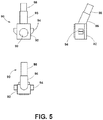
- Fig 5 shows one embodiment of an electromagnetic sensor 90 that includes an electromagnetic sensor head 92 having a substantially box-shape.
- the electromagnetic sensor 90 includes a sensor interface 94 in the form of tabs or ears, such as rigid or flexible tabs, projecting outwardly from opposing sides of the substantially box shaped electromagnetic sensor head 92. Other shaped projections 94 are contemplated.
- the electromagnetic sensor includes a central part 96 disposed between the electromagnetic sensor head 92 at the distal end, and the communication connector 98.
- a slightly raised cylindrical surface 99 is shown on a side of the electromagnetic sensor head 92 to indicate the sensing side to be faced with the tone ring 80.
- the center of the raised cylindrical surface 99 indicates the position of the integrated circuit 62 embedded in the electromagnetic sensor head 92 to be aligned with the tone ring 80.
- Three views of the electromagnetic sensor 90 are provided to show the overall shape thereof.
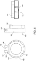
- Fig. 6 shows three views of a flange 100 or spacer for receiving the electromagnetic sensor 90 of Fig. 5 to form a wheel speed sensor.
- the flange includes a metal ring 102 and an outer element 104.
- the flange 100 further includes a flange interface 106 defined by a pair of parallel, outwardly projecting arms 107 facing each other, and a sensor head receiving slot or opening 108 therebetween.
- the arms 107 each include open bore apertures 109 in alignment with each other and are configured to receive the electromagnetic sensor head 92.
- the open bore apertures 109 are configured to receive the tabs 94 of the electromagnetic sensor head 92.
- Fig. 7 shows three views of the electromagnetic sensor 90 and the flange 100 combined to form a wheel speed sensor 110.
- the electromagnetic sensor head 92 is disposed in the sensor head receiving slot 108 and the tabs 94 projecting from the electromagnetic sensor head 92 are locked into the respective apertures 109 of the flange 100.
- At least one of the arms 107 or tabs 94 have a certain amount of elasticity, or are flexible to enable forcing of the electromagnetic sensor head 92 into the slot 108.
- the arms are semi-rigid in some embodiments.
- a snap fit or locking occurs to for the wheel speed sensor 110.
- the pair of parallel spaced arms 107 projecting outwardly from the flange 100 are monolithic with the flange.
- the parallel, spaced arms 107 are attached or secured to the flange 100.
- Fig. 8 shows front and side views of a wheel hub 120.
- the wheel hub 120 includes an annular front face 122, a wheel bearing receiving aperture 124 and an inner face 126.
- the aperture 124 has an inner diameter and the inner face 126 is flat. While not shown, a path through the wheel hub120 for a wheel shaft may be provided.
- Fig. 9 shows front and side views of a wheel bearing 130 having a central open bore aperture 132 extending through the bearing.
- the wheel bearing 130 is dimensioned to fit within the bearing receiving aperture 124 of the wheel hub 120.
- Fig. 10 shows part of a fork 140, typically for mounting to a motorcycle.
- the fork 140 includes an elongated lower fork bar 142 having an open bore fork aperture 144 and an upper fork bar 146 having a greater dimension in one direction than the lower fork bar.
- Fig. 11 shows the components for a portion of a cycle wheel assembly wherein the wheel speed sensor 50 is mounted as a part of the assembly.
- the components shown are the wheel hub 120 that receives the wheel bearing 130 and the tone ring 80. Further, the wheel speed sensor 50 is disposed between the tone ring 80 and the fork 140.
- the components are assembled in the order shown.
- An axle or wheel shaft extends through aligned apertures in the components and into/through the wheel hub 120. The apertures are in axial alignment with each other and similar in diameter.
- Fig. 12 shows the components of Fig. 11 assembled, wherein the wheel hub 120, the wheel speed sensor 50 and the fork 140 visible.
- the wheel hub 120 is configured to receive the wheel bearing 130 and tone ring 80.
- the tone ring 80 is integrated adjacent to the wheel bearing 130 in the wheel hub 120.
- Fig. 13 shows a perspective view of an embodiment of a wheel assembly 150 similar to the arrangement of Fig. 12 .
- a wheel shaft 152 The wheel shaft 152 extends through a fork 154.
- the structure 155 supporting the fork 154 is only for purposes of illustration.
- the wheel speed sensor 156 is disposed adjacent the fork 154 and the wheel hub 158. Portions of the tone ring 160 are visible facing the wheel speed sensor 156.
- the above components all receive the wheel shaft 152 therethrough.
- the components of Fig. 12 operate as a wheel speed monitoring system that operates as set forth below.
- the tone ring shown in Fig. 13 rotates with a wheel (not shown).
- the integrated circuit 62 is disposed between the magnet 64 and the tone ring 80.
- the magnet 64 projects a magnetic field through the integrated circuit 62 and the tone ring 80.
- the tone ring 80 is a magnetic attractive material.
- the tone ring 80 affects the magnetic field projected by the magnet 64. Rotation of the tone ring 80, and specifically movement of the spaced projections 86 of the tone ring 80 past the integrated circuit 62 cause changes in the magnetic field of the magnet 64 that are detected by the integrated circuit.
- the magnetic flux density projected onto the integrated circuit 62 varies in a sinusoidal manner, due to the change in displacement between the magnet 64 and the outer edge of the tone ring 80.
- the integrated circuit 62 contains a magnetic-field sensor such as Hall sensor or Magneto Resistive sensor that senses the variation of the magnetic flux density projected by the magnet 64.
- the integrated circuit 62 sends electrical signal such as current in different amplitudes corresponding to the variation of the magnetic flux density sensed by its magnetic-field sensor to a control unit via the communication connector 54. The frequency of change in the current signal between a low value and a greater value determines the wheel speed.
- rotation of the tone ring 80 relative to the wheel speed sensor 50 alters magnetic flux density projected by the magnet 64 sensed by the integrated circuit 62, and the integrated circuit 62 sends an electrical signal, typically current in different amplitudes as an output that is proportional to rotational speed of the tone ring 80 relative to a control unit via the communication connector 54.
- the above embodiments are all predicated on the flange 70 having an open bore aperture 78 for receiving a wheel shaft.
- the above embodiments are all directed to a wheel speed sensor that is disposed on the wheel shaft and acts as a spacer for components thereon.
- the flange of the wheel speed sensor is provided with various shapes for mounting on a vehicle so that the sensor head is disposed adjacent to an outer part of the tone ring for sensing the passage thereby.
- the outer edge of the flat tone ring has an extension projecting perpendicular to the plane of the flat tone ring and extending about the entire circumference of the outer edge.
- the extension forms a cylindrical shape. Alternating projections from on outer face or apertures are provided in the extension about the entirety of the extension.
- the embodiments disclosed below permit mounting of an electromagnetic sensor to different flanges to enable use with various vehicles.
- the cost and time to develop, test and tool for a large number of wheel speed sensors for various vehicles is minimized, as only a large number of receiving flanges are required, that are less expensive and complicated than wheel speed sensors designed for specific vehicles.
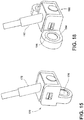
- Fig. 14 shows two views of an embodiment of the wheel speed sensor 170 having the same or similar snap fit arrangement for mounting the electromagnetic sensor 172 to the flange 174 having a bushing 176.
- the arrangement enables a quick and easy snap fitting connection between the electromagnetic sensor 172 and the flange 174.
- the bushing 176 is mounted to a fixed part of a vehicle so that the sensor head is aligned near a tone ring for measuring wheel speed.
- Fig. 15 is a perspective view of the embodiment shown in Fig 14 .
- a fastener (not shown) utilizes the bushing 176 to mount the wheel speed sensor 170.
- Fig. 16 is another embodiment of the wheel speed sensor 180.
- the embodiment of Fig. 16 is similar to the embodiment of Figs. 14 and 15 , except the bushing 186 of the flange 184 is oriented perpendicular and sidewardly from the bushing arrangement shown in Figs. 14 and 15 .
- the wheel speed sensor 180 of Fig. 16 is mounted in a different vehicle or mounting location to provide the sensor head adjacent the tone ring.
- Fig. 17 is two views of another embodiment of the wheel speed sensor 190.
- the electromagnetic sensor 192 has the same snap mounting arrangement with the flange 194 as the embodiments discussed above.
- the flange 194 includes a pair of bushings 196 for mounting the wheel speed sensor 190.
- Fig. 18 is a perspective view the wheel speed sensor 190.
- flanges have bushings that are at 45, 75, 135 or other degree angles with respect to a rear or side of the sensor head of the wheel speed sensor.
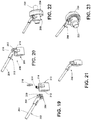
- Figs. 19 and 20 show an embodiment of a wheel speed sensor 200 corresponding to the claimed invention. More specifically, Fig. 19 shows an unassembled wheel speed sensor that includes an electromagnetic sensor 202 having a communication connector 204 at a proximal end an electromagnetic sensor head 206 at a distal end.
- the electromagnetic sensor head 206 is substantially box shaped.
- the electromagnetic sensor 202 has a sensor interface defined by a slot 208 extending about at least three sides of the substantially box-shaped electromagnetic sensor head 206.
- the slot 208 is defined by a narrow lip 209 at the tone ring facing end of the electromagnetic sensor head 206.
- the substantially box-shaped electromagnetic sensor head 206 is defined by an essentially flat face at the tone ring facing end.
- Fig, 19 also shows a flange 210 that acts as a spacer when placed on a wheel shaft.
- the flange has an annular shape and an open bore aperture 212 for receiving a wheel shaft.
- the flange also has a flange interface comprising a pair of parallel outwardly projecting arms 214 having inwardly oriented projections at the distal ends thereof to receive the electromagnetic sensor head 206.
- a retainer element 216 is provided for securing the electromagnetic sensor 202 to the flange 210.
- Fig. 20 shows the assembled wheel speed sensor 200 formed from the components shown in Fig. 19 . More specifically, the electromagnetic sensor head 206 of the electromagnetic sensor 202 is located between the arms 214 that have inwardly oriented projections at the distal ends. A lip at the rear of the electromagnetic sensor head 206 contacts the arms 214 while the slot 208 is adjacent the opposing side of the arms 214. Then the retainer element 216 is seated in the slot 208 to lock the electromagnetic sensor 202 and the flange 210 together to form the wheel speed sensor 200 that is prepared for use with a wheel shaft.
- the wheel speed sensor 220 shown in Fig. 21 is essentially identical to the wheel speed sensor 200 shown in Fig. 20 , except the flange has a reduced length and the pair of parallel outwardly projecting arms are not centered on an outer wall of the cylindrical shaped flange.
- Figs. 22 and 23 show the wheel speed sensor 200 of Fig. 20 disposed on a wheel shaft 222 adjacent a wheel hub 224.
- the perspective view of Fig. 23 shows a tone ring 226 disposed in or adjacent the wheel hub 224 that rotates with a wheel hub.
- the wheel speed sensor 200 measures wheel speed in a similar manner to the embodiment discussed above.
- Fig. 24 does not correspond to the claimed invention and shows the electromagnetic sensor 202 and a separate retainer element 216 of Fig. 19 , along with a plurality of different flanges 230, 232, 234, 236.
- the different flanges have bushings for mounted to a fixed part of a vehicle.
- the bushings have different orientations with respect the electromagnetic sensor head 206 of the electromagnetic sensor 202.
- the flange for a specific vehicle is selected, secured to the electromagnetic sensor 202 to form a wheel speed sensor with the retainer element 216, and mounted to a vehicle adjacent a tone ring via the bushings and a fastener (not shown).
- Fig. 25 shows wheel speed sensors 240, 242, 244, 246 assembled from the electromagnetic sensor 202 and the respective flanges 230, 232, 234, 236 shown in Fig. 24 .
- the invention provides, among other things, an easy approach to providing an easy to assemble wheel speed sensor for mounting on any vehicle.
- the invention enables a vehicle manufacturer to use a common, validated electromagnetic sensor design, with different mounting flanges for different vehicles that have different mounting constraints, thus substantially reduces the time and costs for developing, testing and tooling for different wheel speed sensors, as the cost of developing and tooling a new flange, which is a mechanical component that is less complicated than the electromagnetic sensor is minimal compared to a complete wheel speed sensor.
Landscapes
- Physics & Mathematics (AREA)
- General Physics & Mathematics (AREA)
- Engineering & Computer Science (AREA)
- Power Engineering (AREA)
- Regulating Braking Force (AREA)
Claims (8)
- Capteur de vitesse de roue (200), comprenant :un capteur électromagnétique (52 ; 202), comprenant :une tête de capteur électromagnétique sensiblement en forme de boîte (60 ; 206) disposée à une extrémité distale du capteur électromagnétique (52 ; 202), la tête de capteur électromagnétique (60 ; 206) comprenant un aimant (64) et un circuit intégré (62), la tête de capteur électromagnétique (60 ; 206) étant configurée pour détecter un mouvement par une bague de tonalité (80) comprenant un matériau attractif magnétique ;un connecteur de communication (54 ; 204) disposé à une extrémité proximale du capteur électromagnétique (52 ; 204) et en communication avec la tête de capteur électromagnétique (60 ; 206) ;une interface de capteur disposée à l'extrémité distale du capteur électromagnétique (52 ; 202), l'interface de capteur comprenant une fente (208) s'étendant sur au moins trois côtés de la tête de capteur électromagnétique sensiblement en forme de boîte (60 ; 206), dans lequel la fente (208) est définie par une lèvre étroite (209) à une extrémité avant de la tête de capteur électromagnétique(60 ; 206), etun élément de retenue séparé (216) ;etune bride (210) ayant une forme annulaire et comprenant une entretoise pour recevoir un essieu (222) d'un véhicule à travers un trou d'alésage ouvert (212) de la bride (210), la bride (210) incluant une interface de bride comprenant une paire de bras espacés parallèles (214) faisant saillie vers l'extérieur à partir de la bride (210) par rapport à un axe du trou d'alésage (212), chacun des bras espacés (214) incluant une saillie à une extrémité distale, vers l'extérieur, de celui-ci, dans lequel les saillies des bras (214) font face l'une vers l'autre ;dans lequel le capteur électromagnétique (52 ; 204) est configuré de telle sorte qu'il puisse être fixé à l'interface de bride par insertion de la tête de capteur électromagnétique sensiblement en forme de boîte entre la paire de bras espacés (214) de l'interface de bride, dans lequel une lèvre à un arrière de la tête de capteur (60 ; 206) entre en contact avec les bras (214) alors que la fente (208) est adjacente à un côté opposé des bras (214), et par fixation de l'élément de retenue (216) à l'intérieur de la fente (208) de la tête de capteur électromagnétique sensiblement en forme de boîte (60 ; 206).
- Capteur de vitesse de roue selon la revendication 1, dans lequel la paire de bras espacés parallèles (214, 214) faisant saillie vers l'extérieur à partir de la bride (210) sont monolithiques avec la bride (210).
- Capteur de vitesse de roue selon la revendication 1, dans lequel la tête de capteur électromagnétique (60 ; 206) est configurée pour détecter un mouvement par une bague de tonalité (80) comprenant une ferrite en tant que matériau attractif magnétique.
- Système de surveillance de vitesse de roue, comprenant :un capteur de vitesse de roueselon l'une des revendications 1 à 3, etune bague de tonalité (80) formée de matériau magnétiquement attractif pour la fixation à un palier de roue ou moyeu de roue (224), la bague de tonalité (80) incluant un trou d'alésage ouvert (212) pour recevoir un essieu (222), la bague de tonalité (80) incluant en outre une de : une pluralité d'éléments saillants (86) faisant saillie vers l'extérieur à partir d'une face de la bague de tonalité (80) et disposés en un motif alterné au moins adjacent à un bord extérieur de l'une face de la bague de tonalité (80), et une pluralité de trous disposés en un motif de trous au moins adjacent à un bord extérieur de l'un face de la bague de tonalité (80),dans lequel la rotation de la bague de tonalité (80) relativement au capteur électromagnétique est configurée pour altérer la densité de champ magnétique projetée sur le circuit intégré (62), et le circuit intégré (62) est configuré pour fournir une sortie électrique qui est proportionnelle à une vitesse de rotation de la bague de tonalité (80) relativement au capteur électromagnétique.
- Système de surveillance de vitesse de roue selon la revendication 4, comprenant en outre :
un palier de roue (224) ayant un trou (212) pour recevoir un essieu (222), et le palier de roue (224) étant configuré pour recevoir la bague de tonalité (80). - Système de surveillance de vitesse de roue selon la revendication 4, dans lequel la bride (210) comprend une bague de forme cylindrique et un élément extérieur s'étendant vers l'extérieur sur une partie de la surface circonférentielle extérieure de la bague de forme cylindrique, la bride (210) incluant un trou d'alésage ouvert (212) pour recevoir un essieu (222), dans lequel la bride (210) sert d'entretoise (210) le long de l'essieu (222).
- Système de surveillance de vitesse de roue selon la revendication 4, dans lequel l'aimant (64) et le circuit intégré (62) de la tête de capteur électromagnétique comprennent un capteur de champ magnétique.
- Système de surveillance de vitesse de roue selon la revendication 4, dans lequel la pluralité d'éléments saillants (86), faisant saillie vers l'extérieur à partir d'une face de la bague de tonalité (80) et disposés en un motif, comprend des stries et des creux formant des arêtes s'étendant vers l'extérieur vers le bord extérieur de la bague de tonalité (80), dans lequel le capteur électromagnétique est configuré pour détecter les creux et stries durant la rotation de la bague de tonalité (80).
Applications Claiming Priority (2)
| Application Number | Priority Date | Filing Date | Title |
|---|---|---|---|
| US201461978568P | 2014-04-11 | 2014-04-11 | |
| PCT/US2015/012444 WO2015156888A1 (fr) | 2014-04-11 | 2015-01-22 | Capteur de vitesse de roue |
Publications (2)
| Publication Number | Publication Date |
|---|---|
| EP3129792A1 EP3129792A1 (fr) | 2017-02-15 |
| EP3129792B1 true EP3129792B1 (fr) | 2021-06-02 |
Family
ID=52444672
Family Applications (1)
| Application Number | Title | Priority Date | Filing Date |
|---|---|---|---|
| EP15702359.9A Active EP3129792B1 (fr) | 2014-04-11 | 2015-01-22 | Capteur de vitesse de roue |
Country Status (4)
| Country | Link |
|---|---|
| US (1) | US10488427B2 (fr) |
| EP (1) | EP3129792B1 (fr) |
| CN (1) | CN106461698B (fr) |
| WO (1) | WO2015156888A1 (fr) |
Families Citing this family (7)
| Publication number | Priority date | Publication date | Assignee | Title |
|---|---|---|---|---|
| CN109406815A (zh) * | 2017-08-17 | 2019-03-01 | 西北农林科技大学 | 一种霍尔传感器测速模块安装机构 |
| IT201800004657A1 (it) * | 2018-04-18 | 2019-10-18 | Gruppo mozzo ruota provvisto di un innovativo supporto porta sensore | |
| DE102019115401B3 (de) * | 2019-06-06 | 2020-06-25 | Innotorq Gmbh | Radnabe, hilfsangetriebenes Fahrzeug mit der Radnabe und Klammeranordnung |
| US11890943B1 (en) | 2019-12-04 | 2024-02-06 | Parker-Hannifin Corporation | High-resolution wheel speed sensor for a vehicle |
| US12052944B2 (en) * | 2020-11-03 | 2024-08-06 | Harvest International, Inc. | Rotational speed sensors for agricultural seed planter |
| KR102330813B1 (ko) * | 2021-06-11 | 2021-12-01 | 아센텍 주식회사 | 자율주행 차량용 센싱 축 가변형 휠 속도 센서 장치 |
| US20240402210A1 (en) * | 2023-06-02 | 2024-12-05 | Allegro Microsystems, Llc | Sensor having low power movement detection |
Family Cites Families (37)
| Publication number | Priority date | Publication date | Assignee | Title |
|---|---|---|---|---|
| US3911302A (en) * | 1974-11-27 | 1975-10-07 | Rockwell International Corp | Wheel speed sensor module assembly |
| JPS6026872A (ja) * | 1983-07-20 | 1985-02-09 | 豊田合成株式会社 | ホ−ス中間保持具 |
| US4940936A (en) | 1989-02-24 | 1990-07-10 | The Torrington Company | Antifriction bearing with a clip-on sensor cooperating with a shaft mounted magnetic encoder retainer ring |
| FR2660975B1 (fr) | 1990-04-13 | 1992-06-19 | Roulements Soc Nouvelle | Palier a corps roulants equipe d'un dispositif capteur d'informations orientable. |
| US5166611A (en) * | 1992-01-08 | 1992-11-24 | Production Research, Inc. | Tone wheel with coined serrations for engaging an annular support surface and method of assembling same on a wheel bearing seal |
| FR2710985B1 (fr) * | 1993-10-06 | 1995-11-24 | Skf France | Elément codeur pour roulement muni d'un ensemble capteur d'informations et roulement comportant un tel élément codeur. |
| US5614822A (en) * | 1994-01-28 | 1997-03-25 | Nsk Ltd. | Rolling bearing unit with rotational speed detection device having a tone wheel and a sensor |
| FR2756879A1 (fr) * | 1996-12-06 | 1998-06-12 | Adwest Oci Sa | Dispositif d'assemblage d'un corps de revolution sur un support, au moyen d'une agrafe |
| US5920193A (en) | 1997-05-19 | 1999-07-06 | Itt Manufacturing Enterprises, Inc. | Snap-fit integrated wheel speed sensor assembly |
| JP2000019190A (ja) * | 1998-07-03 | 2000-01-21 | Koyo Seiko Co Ltd | ホイール軸受装置 |
| US6463818B1 (en) * | 2000-04-04 | 2002-10-15 | International Truck Intellectual Property Company, L.L.C. | High retention force anti-lock brake sensor clip |
| JP2002340922A (ja) | 2001-01-25 | 2002-11-27 | Nsk Ltd | 車輪用回転検出装置 |
| US6570375B2 (en) | 2001-03-08 | 2003-05-27 | Daimlerchrysler Corporation | Wheel speed sensor with positive mounting latch |
| FR2823811B1 (fr) | 2001-04-18 | 2003-08-22 | Skf Ab | Ensemble mecanique comprenant un palier a roulement instrumente |
| DE10210184A1 (de) * | 2002-03-07 | 2003-09-18 | Philips Intellectual Property | Anordnung zum Bestimmen der Position eines Bewegungsgeberelements |
| US6911817B2 (en) | 2002-12-23 | 2005-06-28 | American Electronics Components, Inc. | Wheel-speed sensor |
| CN1800859A (zh) | 2004-12-31 | 2006-07-12 | 比亚迪股份有限公司 | 一种传感器制造工艺 |
| JP4522278B2 (ja) | 2005-01-25 | 2010-08-11 | Ntn株式会社 | 回転速度検出装置付き軸受装置 |
| FR2883052A1 (fr) | 2005-03-08 | 2006-09-15 | Raymond Et Cie Soc En Commandi | Dispositif d'assemblage d'un element de connexion sur un support fixe |
| CA2550527A1 (fr) * | 2005-06-21 | 2006-12-21 | Ideal Industries, Inc. | Sectionneur electrique muni de connecteurs a enfoncer |
| DE102005030364B4 (de) * | 2005-06-29 | 2011-01-27 | Siemens Ag | Verfahren zum Erzeugen einer Röntgenbildfolge sowie ein Röntgenbildaufnahmesystem |
| US7503213B2 (en) * | 2006-04-27 | 2009-03-17 | American Axle & Manufacturing, Inc. | Bimetallic sensor mount for axles |
| JP2007303416A (ja) | 2006-05-12 | 2007-11-22 | Toyota Industries Corp | 可変容量型圧縮機 |
| JP2008180617A (ja) | 2007-01-25 | 2008-08-07 | Ntn Corp | 回転速度検出装置付き車輪用軸受装置 |
| US8237431B2 (en) | 2007-07-05 | 2012-08-07 | Terry Fruehling | Wheel speed sensor |
| US8136994B2 (en) * | 2007-10-10 | 2012-03-20 | Jtekt Corporation | Sensor-equipped rolling bearing apparatus |
| JP2009144812A (ja) | 2007-12-13 | 2009-07-02 | Jtekt Corp | センサ付き軸受装置 |
| US8253413B2 (en) * | 2008-09-22 | 2012-08-28 | Infineon Technologies Ag | System that obtains a switching point with the encoder in a static position |
| JP5166218B2 (ja) | 2008-11-25 | 2013-03-21 | 株式会社ジェイテクト | センサー付き転がり軸受装置 |
| EP2417463A1 (fr) | 2009-04-07 | 2012-02-15 | Aktiebolaget SKF | Ensemble palier à roulement comportant des moyens de détection de rotation, et dispositif équipé d'un tel ensemble |
| WO2010133924A1 (fr) | 2009-05-19 | 2010-11-25 | Aktiebolaget Skf | Élément support, dispositif de rotation comprenant un tel support, et ensemble de roulement à billes comprenant un tel dispositif de détection |
| JP5349157B2 (ja) | 2009-06-19 | 2013-11-20 | Ntn株式会社 | 回転検出装置および回転検出装置付き軸受 |
| DE102009054521A1 (de) * | 2009-07-28 | 2011-02-03 | Continental Teves Ag & Co. Ohg | Drehzahlsensor |
| US9787503B2 (en) * | 2010-07-12 | 2017-10-10 | Cisco Technology, Inc. | Utilizing proxy internet protocol addressing in a gateway for communicating with multiple service provider networks |
| WO2013098584A1 (fr) | 2011-12-28 | 2013-07-04 | Aktiebolaget Skf | Ensemble palier et machine électrique tournante comportant un tel palier |
| US8860404B2 (en) * | 2012-06-18 | 2014-10-14 | Allegro Microsystems, Llc | Magnetic field sensors and related techniques that can provide a self-test using signals and related thresholds |
| CN203011935U (zh) | 2012-09-03 | 2013-06-19 | 大陆汽车电子(长春)有限公司 | 轮速传感器 |
-
2015
- 2015-01-22 EP EP15702359.9A patent/EP3129792B1/fr active Active
- 2015-01-22 US US15/127,703 patent/US10488427B2/en active Active
- 2015-01-22 CN CN201580019034.8A patent/CN106461698B/zh not_active Expired - Fee Related
- 2015-01-22 WO PCT/US2015/012444 patent/WO2015156888A1/fr not_active Ceased
Non-Patent Citations (1)
| Title |
|---|
| None * |
Also Published As
| Publication number | Publication date |
|---|---|
| US10488427B2 (en) | 2019-11-26 |
| CN106461698A (zh) | 2017-02-22 |
| WO2015156888A1 (fr) | 2015-10-15 |
| CN106461698B (zh) | 2020-08-11 |
| EP3129792A1 (fr) | 2017-02-15 |
| US20170176488A1 (en) | 2017-06-22 |
Similar Documents
| Publication | Publication Date | Title |
|---|---|---|
| EP3129792B1 (fr) | Capteur de vitesse de roue | |
| EP1584908B1 (fr) | Détecteur de couple et son procédé de fabrication | |
| JP6578343B2 (ja) | 自動車シャシーセンサ | |
| KR101127869B1 (ko) | 차이 각의 검출을 위한 센서 장치 | |
| JP5870607B2 (ja) | レゾルバ及びレゾルバ付き転がり軸受装置 | |
| US8823366B2 (en) | Non-contacting sensor assembly | |
| JPH0649826U (ja) | 軸受用シール装置及び軸受装置 | |
| US5583431A (en) | Hub unit with rotation speed sensor | |
| JP2008268016A (ja) | 車輪速センサ | |
| CN110831792A (zh) | 角度测量装置的布置方式 | |
| US6037766A (en) | Wheel bearing rotary motion sensor having sensor-accommodating housing | |
| CN102365552A (zh) | 车轮用旋转传感器装置 | |
| JPH04102062U (ja) | 回転速度のセンサ装置及びその装置を備えた回転軸受 | |
| JP2007212198A (ja) | トルク検出装置及びこれの製造方法 | |
| JP4135493B2 (ja) | 回転検出センサ | |
| JP4672052B2 (ja) | 回転センサ装置 | |
| US7320258B2 (en) | Structure of attaching a rotation-detecting sensor | |
| CN105513893A (zh) | 开关 | |
| JP2000142341A (ja) | 回転速度検出装置付回転支持装置 | |
| JP2926865B2 (ja) | 回転速度検出用転がり軸受ユニット | |
| JPH07260511A (ja) | 磁気式回転位置検出器 | |
| JP2008157762A (ja) | トルク測定器 | |
| JP3700202B2 (ja) | 回転速度検出装置付転がり軸受ユニット | |
| JP5101711B2 (ja) | スピードセンサーアセンブリー | |
| JPH112639A (ja) | 回転速度検出装置付転がり軸受ユニット |
Legal Events
| Date | Code | Title | Description |
|---|---|---|---|
| STAA | Information on the status of an ep patent application or granted ep patent |
Free format text: STATUS: THE INTERNATIONAL PUBLICATION HAS BEEN MADE |
|
| PUAI | Public reference made under article 153(3) epc to a published international application that has entered the european phase |
Free format text: ORIGINAL CODE: 0009012 |
|
| STAA | Information on the status of an ep patent application or granted ep patent |
Free format text: STATUS: REQUEST FOR EXAMINATION WAS MADE |
|
| 17P | Request for examination filed |
Effective date: 20161111 |
|
| AK | Designated contracting states |
Kind code of ref document: A1 Designated state(s): AL AT BE BG CH CY CZ DE DK EE ES FI FR GB GR HR HU IE IS IT LI LT LU LV MC MK MT NL NO PL PT RO RS SE SI SK SM TR |
|
| AX | Request for extension of the european patent |
Extension state: BA ME |
|
| DAX | Request for extension of the european patent (deleted) | ||
| STAA | Information on the status of an ep patent application or granted ep patent |
Free format text: STATUS: EXAMINATION IS IN PROGRESS |
|
| 17Q | First examination report despatched |
Effective date: 20180301 |
|
| RAP1 | Party data changed (applicant data changed or rights of an application transferred) |
Owner name: ROBERT BOSCH GMBH |
|
| GRAP | Despatch of communication of intention to grant a patent |
Free format text: ORIGINAL CODE: EPIDOSNIGR1 |
|
| STAA | Information on the status of an ep patent application or granted ep patent |
Free format text: STATUS: GRANT OF PATENT IS INTENDED |
|
| INTG | Intention to grant announced |
Effective date: 20210201 |
|
| GRAS | Grant fee paid |
Free format text: ORIGINAL CODE: EPIDOSNIGR3 |
|
| GRAA | (expected) grant |
Free format text: ORIGINAL CODE: 0009210 |
|
| STAA | Information on the status of an ep patent application or granted ep patent |
Free format text: STATUS: THE PATENT HAS BEEN GRANTED |
|
| REG | Reference to a national code |
Ref country code: CH Ref legal event code: EP |
|
| AK | Designated contracting states |
Kind code of ref document: B1 Designated state(s): AL AT BE BG CH CY CZ DE DK EE ES FI FR GB GR HR HU IE IS IT LI LT LU LV MC MK MT NL NO PL PT RO RS SE SI SK SM TR |
|
| REG | Reference to a national code |
Ref country code: GB Ref legal event code: FG4D |
|
| REG | Reference to a national code |
Ref country code: AT Ref legal event code: REF Ref document number: 1398951 Country of ref document: AT Kind code of ref document: T Effective date: 20210615 |
|
| REG | Reference to a national code |
Ref country code: IE Ref legal event code: FG4D |
|
| REG | Reference to a national code |
Ref country code: DE Ref legal event code: R096 Ref document number: 602015069942 Country of ref document: DE |
|
| REG | Reference to a national code |
Ref country code: LT Ref legal event code: MG9D |
|
| PG25 | Lapsed in a contracting state [announced via postgrant information from national office to epo] |
Ref country code: HR Free format text: LAPSE BECAUSE OF FAILURE TO SUBMIT A TRANSLATION OF THE DESCRIPTION OR TO PAY THE FEE WITHIN THE PRESCRIBED TIME-LIMIT Effective date: 20210602 Ref country code: BG Free format text: LAPSE BECAUSE OF FAILURE TO SUBMIT A TRANSLATION OF THE DESCRIPTION OR TO PAY THE FEE WITHIN THE PRESCRIBED TIME-LIMIT Effective date: 20210902 Ref country code: LT Free format text: LAPSE BECAUSE OF FAILURE TO SUBMIT A TRANSLATION OF THE DESCRIPTION OR TO PAY THE FEE WITHIN THE PRESCRIBED TIME-LIMIT Effective date: 20210602 Ref country code: FI Free format text: LAPSE BECAUSE OF FAILURE TO SUBMIT A TRANSLATION OF THE DESCRIPTION OR TO PAY THE FEE WITHIN THE PRESCRIBED TIME-LIMIT Effective date: 20210602 |
|
| REG | Reference to a national code |
Ref country code: NL Ref legal event code: MP Effective date: 20210602 |
|
| REG | Reference to a national code |
Ref country code: AT Ref legal event code: MK05 Ref document number: 1398951 Country of ref document: AT Kind code of ref document: T Effective date: 20210602 |
|
| PG25 | Lapsed in a contracting state [announced via postgrant information from national office to epo] |
Ref country code: LV Free format text: LAPSE BECAUSE OF FAILURE TO SUBMIT A TRANSLATION OF THE DESCRIPTION OR TO PAY THE FEE WITHIN THE PRESCRIBED TIME-LIMIT Effective date: 20210602 Ref country code: GR Free format text: LAPSE BECAUSE OF FAILURE TO SUBMIT A TRANSLATION OF THE DESCRIPTION OR TO PAY THE FEE WITHIN THE PRESCRIBED TIME-LIMIT Effective date: 20210903 Ref country code: SE Free format text: LAPSE BECAUSE OF FAILURE TO SUBMIT A TRANSLATION OF THE DESCRIPTION OR TO PAY THE FEE WITHIN THE PRESCRIBED TIME-LIMIT Effective date: 20210602 Ref country code: RS Free format text: LAPSE BECAUSE OF FAILURE TO SUBMIT A TRANSLATION OF THE DESCRIPTION OR TO PAY THE FEE WITHIN THE PRESCRIBED TIME-LIMIT Effective date: 20210602 Ref country code: NO Free format text: LAPSE BECAUSE OF FAILURE TO SUBMIT A TRANSLATION OF THE DESCRIPTION OR TO PAY THE FEE WITHIN THE PRESCRIBED TIME-LIMIT Effective date: 20210902 Ref country code: PL Free format text: LAPSE BECAUSE OF FAILURE TO SUBMIT A TRANSLATION OF THE DESCRIPTION OR TO PAY THE FEE WITHIN THE PRESCRIBED TIME-LIMIT Effective date: 20210602 |
|
| PG25 | Lapsed in a contracting state [announced via postgrant information from national office to epo] |
Ref country code: AT Free format text: LAPSE BECAUSE OF FAILURE TO SUBMIT A TRANSLATION OF THE DESCRIPTION OR TO PAY THE FEE WITHIN THE PRESCRIBED TIME-LIMIT Effective date: 20210602 Ref country code: ES Free format text: LAPSE BECAUSE OF FAILURE TO SUBMIT A TRANSLATION OF THE DESCRIPTION OR TO PAY THE FEE WITHIN THE PRESCRIBED TIME-LIMIT Effective date: 20210602 Ref country code: PT Free format text: LAPSE BECAUSE OF FAILURE TO SUBMIT A TRANSLATION OF THE DESCRIPTION OR TO PAY THE FEE WITHIN THE PRESCRIBED TIME-LIMIT Effective date: 20211004 Ref country code: NL Free format text: LAPSE BECAUSE OF FAILURE TO SUBMIT A TRANSLATION OF THE DESCRIPTION OR TO PAY THE FEE WITHIN THE PRESCRIBED TIME-LIMIT Effective date: 20210602 Ref country code: RO Free format text: LAPSE BECAUSE OF FAILURE TO SUBMIT A TRANSLATION OF THE DESCRIPTION OR TO PAY THE FEE WITHIN THE PRESCRIBED TIME-LIMIT Effective date: 20210602 Ref country code: EE Free format text: LAPSE BECAUSE OF FAILURE TO SUBMIT A TRANSLATION OF THE DESCRIPTION OR TO PAY THE FEE WITHIN THE PRESCRIBED TIME-LIMIT Effective date: 20210602 Ref country code: CZ Free format text: LAPSE BECAUSE OF FAILURE TO SUBMIT A TRANSLATION OF THE DESCRIPTION OR TO PAY THE FEE WITHIN THE PRESCRIBED TIME-LIMIT Effective date: 20210602 Ref country code: SK Free format text: LAPSE BECAUSE OF FAILURE TO SUBMIT A TRANSLATION OF THE DESCRIPTION OR TO PAY THE FEE WITHIN THE PRESCRIBED TIME-LIMIT Effective date: 20210602 Ref country code: SM Free format text: LAPSE BECAUSE OF FAILURE TO SUBMIT A TRANSLATION OF THE DESCRIPTION OR TO PAY THE FEE WITHIN THE PRESCRIBED TIME-LIMIT Effective date: 20210602 |
|
| REG | Reference to a national code |
Ref country code: DE Ref legal event code: R097 Ref document number: 602015069942 Country of ref document: DE |
|
| PLBE | No opposition filed within time limit |
Free format text: ORIGINAL CODE: 0009261 |
|
| STAA | Information on the status of an ep patent application or granted ep patent |
Free format text: STATUS: NO OPPOSITION FILED WITHIN TIME LIMIT |
|
| PG25 | Lapsed in a contracting state [announced via postgrant information from national office to epo] |
Ref country code: DK Free format text: LAPSE BECAUSE OF FAILURE TO SUBMIT A TRANSLATION OF THE DESCRIPTION OR TO PAY THE FEE WITHIN THE PRESCRIBED TIME-LIMIT Effective date: 20210602 |
|
| 26N | No opposition filed |
Effective date: 20220303 |
|
| PG25 | Lapsed in a contracting state [announced via postgrant information from national office to epo] |
Ref country code: AL Free format text: LAPSE BECAUSE OF FAILURE TO SUBMIT A TRANSLATION OF THE DESCRIPTION OR TO PAY THE FEE WITHIN THE PRESCRIBED TIME-LIMIT Effective date: 20210602 |
|
| PG25 | Lapsed in a contracting state [announced via postgrant information from national office to epo] |
Ref country code: IT Free format text: LAPSE BECAUSE OF FAILURE TO SUBMIT A TRANSLATION OF THE DESCRIPTION OR TO PAY THE FEE WITHIN THE PRESCRIBED TIME-LIMIT Effective date: 20210602 |
|
| REG | Reference to a national code |
Ref country code: DE Ref legal event code: R119 Ref document number: 602015069942 Country of ref document: DE |
|
| PG25 | Lapsed in a contracting state [announced via postgrant information from national office to epo] |
Ref country code: MC Free format text: LAPSE BECAUSE OF FAILURE TO SUBMIT A TRANSLATION OF THE DESCRIPTION OR TO PAY THE FEE WITHIN THE PRESCRIBED TIME-LIMIT Effective date: 20210602 |
|
| REG | Reference to a national code |
Ref country code: CH Ref legal event code: PL |
|
| GBPC | Gb: european patent ceased through non-payment of renewal fee |
Effective date: 20220122 |
|
| REG | Reference to a national code |
Ref country code: BE Ref legal event code: MM Effective date: 20220131 |
|
| PG25 | Lapsed in a contracting state [announced via postgrant information from national office to epo] |
Ref country code: LU Free format text: LAPSE BECAUSE OF NON-PAYMENT OF DUE FEES Effective date: 20220122 Ref country code: GB Free format text: LAPSE BECAUSE OF NON-PAYMENT OF DUE FEES Effective date: 20220122 Ref country code: DE Free format text: LAPSE BECAUSE OF NON-PAYMENT OF DUE FEES Effective date: 20220802 |
|
| PG25 | Lapsed in a contracting state [announced via postgrant information from national office to epo] |
Ref country code: FR Free format text: LAPSE BECAUSE OF NON-PAYMENT OF DUE FEES Effective date: 20220131 Ref country code: BE Free format text: LAPSE BECAUSE OF NON-PAYMENT OF DUE FEES Effective date: 20220131 |
|
| PG25 | Lapsed in a contracting state [announced via postgrant information from national office to epo] |
Ref country code: LI Free format text: LAPSE BECAUSE OF NON-PAYMENT OF DUE FEES Effective date: 20220131 Ref country code: CH Free format text: LAPSE BECAUSE OF NON-PAYMENT OF DUE FEES Effective date: 20220131 |
|
| PG25 | Lapsed in a contracting state [announced via postgrant information from national office to epo] |
Ref country code: IE Free format text: LAPSE BECAUSE OF NON-PAYMENT OF DUE FEES Effective date: 20220122 |
|
| PG25 | Lapsed in a contracting state [announced via postgrant information from national office to epo] |
Ref country code: HU Free format text: LAPSE BECAUSE OF FAILURE TO SUBMIT A TRANSLATION OF THE DESCRIPTION OR TO PAY THE FEE WITHIN THE PRESCRIBED TIME-LIMIT; INVALID AB INITIO Effective date: 20150122 |
|
| PG25 | Lapsed in a contracting state [announced via postgrant information from national office to epo] |
Ref country code: MK Free format text: LAPSE BECAUSE OF FAILURE TO SUBMIT A TRANSLATION OF THE DESCRIPTION OR TO PAY THE FEE WITHIN THE PRESCRIBED TIME-LIMIT Effective date: 20210602 Ref country code: CY Free format text: LAPSE BECAUSE OF FAILURE TO SUBMIT A TRANSLATION OF THE DESCRIPTION OR TO PAY THE FEE WITHIN THE PRESCRIBED TIME-LIMIT Effective date: 20210602 |
|
| PG25 | Lapsed in a contracting state [announced via postgrant information from national office to epo] |
Ref country code: MT Free format text: LAPSE BECAUSE OF FAILURE TO SUBMIT A TRANSLATION OF THE DESCRIPTION OR TO PAY THE FEE WITHIN THE PRESCRIBED TIME-LIMIT Effective date: 20210602 |
|
| PG25 | Lapsed in a contracting state [announced via postgrant information from national office to epo] |
Ref country code: TR Free format text: LAPSE BECAUSE OF FAILURE TO SUBMIT A TRANSLATION OF THE DESCRIPTION OR TO PAY THE FEE WITHIN THE PRESCRIBED TIME-LIMIT Effective date: 20210602 |