EP3008440B1 - Kapazitive, keramische druckmesszelle und verfahren zu ihrer herstellung - Google Patents
Kapazitive, keramische druckmesszelle und verfahren zu ihrer herstellung Download PDFInfo
- Publication number
- EP3008440B1 EP3008440B1 EP14724476.8A EP14724476A EP3008440B1 EP 3008440 B1 EP3008440 B1 EP 3008440B1 EP 14724476 A EP14724476 A EP 14724476A EP 3008440 B1 EP3008440 B1 EP 3008440B1
- Authority
- EP
- European Patent Office
- Prior art keywords
- measuring cell
- pressure
- counter
- pressure measuring
- membrane
- Prior art date
- Legal status (The legal status is an assumption and is not a legal conclusion. Google has not performed a legal analysis and makes no representation as to the accuracy of the status listed.)
- Active
Links
Images

Classifications
-
- G—PHYSICS
- G01—MEASURING; TESTING
- G01L—MEASURING FORCE, STRESS, TORQUE, WORK, MECHANICAL POWER, MECHANICAL EFFICIENCY, OR FLUID PRESSURE
- G01L9/00—Measuring steady of quasi-steady pressure of fluid or fluent solid material by electric or magnetic pressure-sensitive elements; Transmitting or indicating the displacement of mechanical pressure-sensitive elements, used to measure the steady or quasi-steady pressure of a fluid or fluent solid material, by electric or magnetic means
- G01L9/0041—Transmitting or indicating the displacement of flexible diaphragms
- G01L9/0072—Transmitting or indicating the displacement of flexible diaphragms using variations in capacitance
-
- G—PHYSICS
- G01—MEASURING; TESTING
- G01L—MEASURING FORCE, STRESS, TORQUE, WORK, MECHANICAL POWER, MECHANICAL EFFICIENCY, OR FLUID PRESSURE
- G01L9/00—Measuring steady of quasi-steady pressure of fluid or fluent solid material by electric or magnetic pressure-sensitive elements; Transmitting or indicating the displacement of mechanical pressure-sensitive elements, used to measure the steady or quasi-steady pressure of a fluid or fluent solid material, by electric or magnetic means
- G01L9/0041—Transmitting or indicating the displacement of flexible diaphragms
- G01L9/0072—Transmitting or indicating the displacement of flexible diaphragms using variations in capacitance
- G01L9/0075—Transmitting or indicating the displacement of flexible diaphragms using variations in capacitance using a ceramic diaphragm, e.g. alumina, fused quartz, glass
-
- B—PERFORMING OPERATIONS; TRANSPORTING
- B23—MACHINE TOOLS; METAL-WORKING NOT OTHERWISE PROVIDED FOR
- B23K—SOLDERING OR UNSOLDERING; WELDING; CLADDING OR PLATING BY SOLDERING OR WELDING; CUTTING BY APPLYING HEAT LOCALLY, e.g. FLAME CUTTING; WORKING BY LASER BEAM
- B23K1/00—Soldering, e.g. brazing, or unsoldering
- B23K1/0008—Soldering, e.g. brazing, or unsoldering specially adapted for particular articles or work
- B23K1/0016—Soldering of electronic components
-
- B—PERFORMING OPERATIONS; TRANSPORTING
- B23—MACHINE TOOLS; METAL-WORKING NOT OTHERWISE PROVIDED FOR
- B23K—SOLDERING OR UNSOLDERING; WELDING; CLADDING OR PLATING BY SOLDERING OR WELDING; CUTTING BY APPLYING HEAT LOCALLY, e.g. FLAME CUTTING; WORKING BY LASER BEAM
- B23K1/00—Soldering, e.g. brazing, or unsoldering
- B23K1/19—Soldering, e.g. brazing, or unsoldering taking account of the properties of the materials to be soldered
-
- C—CHEMISTRY; METALLURGY
- C23—COATING METALLIC MATERIAL; COATING MATERIAL WITH METALLIC MATERIAL; CHEMICAL SURFACE TREATMENT; DIFFUSION TREATMENT OF METALLIC MATERIAL; COATING BY VACUUM EVAPORATION, BY SPUTTERING, BY ION IMPLANTATION OR BY CHEMICAL VAPOUR DEPOSITION, IN GENERAL; INHIBITING CORROSION OF METALLIC MATERIAL OR INCRUSTATION IN GENERAL
- C23C—COATING METALLIC MATERIAL; COATING MATERIAL WITH METALLIC MATERIAL; SURFACE TREATMENT OF METALLIC MATERIAL BY DIFFUSION INTO THE SURFACE, BY CHEMICAL CONVERSION OR SUBSTITUTION; COATING BY VACUUM EVAPORATION, BY SPUTTERING, BY ION IMPLANTATION OR BY CHEMICAL VAPOUR DEPOSITION, IN GENERAL
- C23C14/00—Coating by vacuum evaporation, by sputtering or by ion implantation of the coating forming material
- C23C14/0021—Reactive sputtering or evaporation
- C23C14/0036—Reactive sputtering
-
- C—CHEMISTRY; METALLURGY
- C23—COATING METALLIC MATERIAL; COATING MATERIAL WITH METALLIC MATERIAL; CHEMICAL SURFACE TREATMENT; DIFFUSION TREATMENT OF METALLIC MATERIAL; COATING BY VACUUM EVAPORATION, BY SPUTTERING, BY ION IMPLANTATION OR BY CHEMICAL VAPOUR DEPOSITION, IN GENERAL; INHIBITING CORROSION OF METALLIC MATERIAL OR INCRUSTATION IN GENERAL
- C23C—COATING METALLIC MATERIAL; COATING MATERIAL WITH METALLIC MATERIAL; SURFACE TREATMENT OF METALLIC MATERIAL BY DIFFUSION INTO THE SURFACE, BY CHEMICAL CONVERSION OR SUBSTITUTION; COATING BY VACUUM EVAPORATION, BY SPUTTERING, BY ION IMPLANTATION OR BY CHEMICAL VAPOUR DEPOSITION, IN GENERAL
- C23C14/00—Coating by vacuum evaporation, by sputtering or by ion implantation of the coating forming material
- C23C14/06—Coating by vacuum evaporation, by sputtering or by ion implantation of the coating forming material characterised by the coating material
- C23C14/14—Metallic material, boron or silicon
-
- C—CHEMISTRY; METALLURGY
- C23—COATING METALLIC MATERIAL; COATING MATERIAL WITH METALLIC MATERIAL; CHEMICAL SURFACE TREATMENT; DIFFUSION TREATMENT OF METALLIC MATERIAL; COATING BY VACUUM EVAPORATION, BY SPUTTERING, BY ION IMPLANTATION OR BY CHEMICAL VAPOUR DEPOSITION, IN GENERAL; INHIBITING CORROSION OF METALLIC MATERIAL OR INCRUSTATION IN GENERAL
- C23C—COATING METALLIC MATERIAL; COATING MATERIAL WITH METALLIC MATERIAL; SURFACE TREATMENT OF METALLIC MATERIAL BY DIFFUSION INTO THE SURFACE, BY CHEMICAL CONVERSION OR SUBSTITUTION; COATING BY VACUUM EVAPORATION, BY SPUTTERING, BY ION IMPLANTATION OR BY CHEMICAL VAPOUR DEPOSITION, IN GENERAL
- C23C14/00—Coating by vacuum evaporation, by sputtering or by ion implantation of the coating forming material
- C23C14/22—Coating by vacuum evaporation, by sputtering or by ion implantation of the coating forming material characterised by the process of coating
- C23C14/34—Sputtering
-
- C—CHEMISTRY; METALLURGY
- C23—COATING METALLIC MATERIAL; COATING MATERIAL WITH METALLIC MATERIAL; CHEMICAL SURFACE TREATMENT; DIFFUSION TREATMENT OF METALLIC MATERIAL; COATING BY VACUUM EVAPORATION, BY SPUTTERING, BY ION IMPLANTATION OR BY CHEMICAL VAPOUR DEPOSITION, IN GENERAL; INHIBITING CORROSION OF METALLIC MATERIAL OR INCRUSTATION IN GENERAL
- C23C—COATING METALLIC MATERIAL; COATING MATERIAL WITH METALLIC MATERIAL; SURFACE TREATMENT OF METALLIC MATERIAL BY DIFFUSION INTO THE SURFACE, BY CHEMICAL CONVERSION OR SUBSTITUTION; COATING BY VACUUM EVAPORATION, BY SPUTTERING, BY ION IMPLANTATION OR BY CHEMICAL VAPOUR DEPOSITION, IN GENERAL
- C23C8/00—Solid state diffusion of only non-metal elements into metallic material surfaces; Chemical surface treatment of metallic material by reaction of the surface with a reactive gas, leaving reaction products of surface material in the coating, e.g. conversion coatings, passivation of metals
- C23C8/06—Solid state diffusion of only non-metal elements into metallic material surfaces; Chemical surface treatment of metallic material by reaction of the surface with a reactive gas, leaving reaction products of surface material in the coating, e.g. conversion coatings, passivation of metals using gases
- C23C8/08—Solid state diffusion of only non-metal elements into metallic material surfaces; Chemical surface treatment of metallic material by reaction of the surface with a reactive gas, leaving reaction products of surface material in the coating, e.g. conversion coatings, passivation of metals using gases only one element being applied
- C23C8/10—Oxidising
- C23C8/16—Oxidising using oxygen-containing compounds, e.g. water, carbon dioxide
-
- B—PERFORMING OPERATIONS; TRANSPORTING
- B23—MACHINE TOOLS; METAL-WORKING NOT OTHERWISE PROVIDED FOR
- B23K—SOLDERING OR UNSOLDERING; WELDING; CLADDING OR PLATING BY SOLDERING OR WELDING; CUTTING BY APPLYING HEAT LOCALLY, e.g. FLAME CUTTING; WORKING BY LASER BEAM
- B23K2103/00—Materials to be soldered, welded or cut
- B23K2103/50—Inorganic materials other than metals or composite materials
- B23K2103/52—Ceramics
Definitions
- the present invention relates to a capacitive ceramic pressure measuring cell and a method for its production.
- Generic pressure measuring cells have a ceramic measuring membrane and a ceramic counter body, wherein the measuring membrane with the counter-body along a circumferential joint, which in particular has an active brazing, pressure-tight manner, wherein between the measuring membrane and the counter body, a pressure chamber is formed, wherein the equilibrium position of Measuring diaphragm from the difference between a pressure prevailing in the pressure chamber and an acting on the outside of the pressure chamber outside of the measuring membrane pressure results.
- Generic pressure measuring cells further comprise a capacitive transducer for converting the pressure-dependent deformation of the measuring diaphragm into an electrical signal.
- JP 2002 214 059 A discloses a capacitive vacuum pressure sensor not with a ceramic measuring membrane but with a measuring membrane made of silicon, which is to be protected with a protective layer of aluminum oxide, zirconium oxide or titanium oxide against corrosive gases.
- the material used for the counter-body and the measuring membrane are in particular alumina ceramics in use, which are suitable for the production of pressure measuring cells due to their elastic properties and their media resistance.
- the cited ceramic components are in particular joined with an active brazing material, which preferably comprises a Zr-Ni-Ti-containing active brazing material is.
- the preparation of such an active braid is for example in the European patent application EP 0 490 807 A2 disclosed.
- rings can be produced from the Aktivhartiotmaterial, which are to be positioned between the measuring membrane and counter-body in order to solder them together.
- DE 10 2008 036 381 B3 discloses such a pressure sensor with a high-strength measuring membrane having an Al 2 O 3 ceramic, and having a counter body of an alumina ceramic wherein the measuring membrane and the base body are joined by means of an active brazing, for example by means of a Zr-Ni-Ti alloy.
- electrode material for electrodes of the capacitive transducer for example, niobium, tantalum or silicon carbide are known, wherein the surface of the electrodes is optionally protected with a glass layer, as in the publication EP 0 544 934 A1 is described.
- electrodes are known which comprise metallic particles in a glass matrix and, for example, in the published patent application DE 10 2007 026 243 A1 are described.
- Said electrode materials are compatible with a high temperature vacuum soldering process for joining alumina ceramics by means of an active brazing alloy.
- the temperature range in which an active brazing material forms a high-quality, pressure-tight connection to a ceramic material is comparatively narrow. On the other hand, if the temperatures are too low, the solder is not sufficiently reactive and, on the other hand, it is too tough to spread evenly over a surface area to be wetted.
- a practiced method for confining the radially inwardly flowing active braze is to superficially oxidize a membrane electrode which has tantalum and which is to come in galvanic contact with the active brazing material. At comparatively low soldering temperatures, it is thus possible to prevent the active brazing agent from entering the pressure chamber with an acceptable yield. However, if the soldering temperature is increased, this solder stop will no longer be reliable and the solder will flow into the pressure chamber via the edge of the tantalum electrodes.
- the electrodes now have at least two layers with different thermal expansion coefficients, namely a metallic tantalum layer and a tantalum oxide layer. As a result, temperature-dependent mechanical stresses can occur on the surface of the measuring diaphragm which cause a temperature hysteresis.
- the present invention is therefore based on the object to provide a pressure measuring cell, which overcomes the problems mentioned.
- the present invention now pursues the approach to prepare the solder stop and at least the membrane electrode with the same material system, namely titanium oxide, which may optionally be doped, for example with, Cr, Nb, W.
- the pressure measuring cell has a ceramic measuring membrane and a ceramic counter body, wherein the measuring membrane is pressure-tightly joined to the counter body to form a pressure chamber between the measuring diaphragm and the counter body, wherein the measuring diaphragm has a side facing the pressure chamber and a side facing away from the pressure chamber, wherein the pressure measuring cell further comprises a capacitive transducer for detecting a pressure-dependent deformation of the measuring membrane, which has at least one membrane electrode arranged on the diaphragm and at least one counter-body-side electrode, wherein the membrane electrode is disposed on the pressure chamber facing side of the measuring diaphragm, wherein according to the invention at least one Membrane electrode has a titanium oxide.
- the titanium oxide is arranged according to a preferred embodiment of the invention without intermediate layers on the ceramic material of the measuring membrane.
- the membrane electrode has titanium oxide, which is non-stoichiometric, in particular Ti 4 O 7 , Ti 5 O 9 or Ti 6 O 11 .
- Non-stoichiometric titanium oxide has a higher conductivity than stoichiometric titanium oxide and is thus particularly well suited as an electrode material.
- the membrane electrode has doped titanium oxide, which is doped in particular with Cr, Nb or W.
- the doping is up to about 10 atomic%, in particular not more than 8 atomic%, and preferably not more than 6 atomic%, based on the Ti atoms.
- the doping of the titanium oxide leads to an even higher conductivity of the electrode material.
- the measuring membrane is joined by means of an active brazing with the main body, wherein the membrane electrode is in galvanic contact with the active brazing.
- the membrane electrode at the same time serve as a solder stop, which prevents shrinkage of the active braze into the pressure chamber during soldering of the pressure measuring cell.
- the membrane electrode can be contacted via the joint by the lateral surface of the pressure measuring cell, whereby a conductive coating of the lateral surface of the opposing body, which contacts the joint, and possibly a conductive coating of one of the measuring membrane remote from the rear side of the counter body can achieve a shielding of the counter-body-side electrode, in particular in the form of a Faraday cage.
- the ceramic material of the measuring membrane and of the counter body comprise an aluminum oxide ceramic, in particular a high-purity aluminum oxide ceramic, as described, for example, in the German patent DE 10 2008 036 381 B3 is described.
- the purities described there relate in particular to the ceramic of the measuring diaphragm, whereas for the counter-body such high-purity ceramic is not absolutely necessary.
- the active brazing solder comprises a zirconium-nickel-titanium-containing active brazing alloy, as described for example in the European patent application EP 0 490 807 A2 is described.
- At least the membrane electrode is prepared by first sputtering a metal layer, ie a titanium layer or a titanium layer doped, for example, with Cr, Nb, and / or W, which is subsequently thermally oxidized.
- a metal layer ie a titanium layer or a titanium layer doped, for example, with Cr, Nb, and / or W, which is subsequently thermally oxidized.
- the oxidation takes place by heating in an oxygen-containing atmosphere, for example in air, wherein the oxidation takes place the heating to a temperature of not less than 500 ° C, in particular not less than 600 ° C.
- At least the membrane electrode is prepared by reactive sputtering of titanium oxide, which can be doped in particular, in particular with Cr, Nb and / or W.
- the joining of the ceramic components with the active brazing solder takes place at a temperature of not less than 800 ° C., in particular not less than 840 ° C.
- pressure measuring cell 1 comprises a measuring membrane 2, which has high-purity (> 99.9%) of aluminum oxide, and a counter-body 4, which also has aluminum oxide.
- the counter body 4 may have the same purity as the measuring membrane, although this is not absolutely necessary, since the counter body is not in contact with the media, so that the requirements for corrosion resistance are lower and on the other hand is not exposed to the mechanical stresses such as the measuring diaphragm 2.
- the measuring membrane is pressure-tightly connected to the counter body along a peripheral joint 6, which has a Zr-Ni-Ti-containing active solder, forming a pressure chamber between the measuring membrane 2 and the counter body 4.
- the pressure measuring cell 1 For detecting a pressure-dependent deformation of the measuring diaphragm, the pressure measuring cell 1 comprises a differential capacitor, which by a at the Measuring diaphragm 2 arranged membrane electrode 8, a central counter-body-side, circular disk-shaped measuring electrode 10 and a, the measuring electrode surrounding the reference electrode 12 is formed. Ideally, the capacitance between the measuring electrode 10 and the membrane electrode 8 is equal to the capacitance between the reference electrode 12 and the membrane electrode 8 when the measuring diaphragm 2 is in the rest position.
- the membrane electrode 8 comprises titanium oxide, which is prepared directly on the ceramic material of the measuring membrane 2.
- the titanium oxide preferably contains a doping of a few atomic% of Nb, thereby significantly improving the conductivity of the electrode material.
- the reference electrode 12 and the measuring electrode 10 may likewise comprise titanium oxide, which may be doped, or else platinum or tantalum. If tantalum electrodes are used, these are preferably stabilized by thermal oxidation.
- the membrane electrode 8 is electrically contacted via the joint 6 and an electrical feedthrough 20, which extends through the counter body in the radial region of the joint 6.
- the measuring electrode 10 and the reference electrode 12 are contacted directly via electrical feedthroughs 22, 24 through the counter body 4.
- the electrical feedthroughs 20, 22, 24 comprise, for example, tantalum pins, which are soldered by means of an active brazing pressure-tight in holes through the counter body 4.
- the membrane electrode 8 acts as a solder stop, which prevents the active brazing material from being soldered from the edge region radially inwardly into the pressure chamber during soldering of the counter body 4 and the measuring diaphragm 2.
- a circular disk-shaped measuring diaphragm 2 made of high-purity corundum and a stiffer, circular-plate-shaped counter body 4 made of corundum provided.
- the membrane electrode 8 and possibly further electrodes based on titanium oxide comprise or comprise highly oxidized titanium, for example TiO 2 and / or Ti 4 O 7 , which is produced by sputtering of titanium and optionally doping metals (Cr, Nb, W) onto the ceramic Material of the measuring diaphragm 2 and the counter body 4 and subsequent thermal oxidation at 600 ° C is prepared in air.
- highly oxidized titanium for example TiO 2 and / or Ti 4 O 7 , which is produced by sputtering of titanium and optionally doping metals (Cr, Nb, W) onto the ceramic Material of the measuring diaphragm 2 and the counter body 4 and subsequent thermal oxidation at 600 ° C is prepared in air.
- titanium oxide can be deposited directly instead of the metallic titanium by reactive sputtering, as a result of which the subsequent oxidation step can be dispensed with.
- the annular solder preform 5 has, for example, a height of about 30 ⁇ m to 50 ⁇ m.
- the components are soldered in a Hochvakuumlötfrac at temperatures, for example, 950 ° C, the molten active brazing reacts with the ceramic surfaces of the measuring membrane 2 and the counter body 4, but it can not flow over the edge of the membrane electrode 8 in the pressure chamber, since the oxygen from the titanium oxide at least partially enters the solder and thus the solder is clogged, so that it solidifies or becomes highly viscous and does not flow further into the pressure chamber. Nevertheless, there is a galvanic contact between the joint 6 and the membrane electrode 8, so that a metallic coating on a lateral surface of the pressure measuring cell can be brought into contact with the membrane electrode 8 via the joint.
- FIGS. 2a to 2d have been omitted for clarity.
- the feedthroughs are also soldered in the high vacuum soldering process.
- the radial size of the pressure cell is a few 10 mm.
- the height or axial strength of the counter body is for example 3 to 15 mm.
- the thickness of the measuring membrane is for example not less than 100 ⁇ m and, for example, not more than 2000 ⁇ m.
- the layer thickness of the electrodes is about 100 nm. The dimensions are given by way of illustration only and are not to be considered as defining or limiting the invention.
Landscapes
- Chemical & Material Sciences (AREA)
- Engineering & Computer Science (AREA)
- Mechanical Engineering (AREA)
- Materials Engineering (AREA)
- Chemical Kinetics & Catalysis (AREA)
- Metallurgy (AREA)
- Organic Chemistry (AREA)
- Physics & Mathematics (AREA)
- General Physics & Mathematics (AREA)
- Ceramic Engineering (AREA)
- Measuring Fluid Pressure (AREA)
Description
- Die vorliegende Erfindung betrifft eine kapazitive, keramische Druckmesszelle und ein Verfahren zu ihrer Herstellung.
- Gattungsgemäße Druckmesszellen weisen eine keramische Messmembran und einen keramischen Gegenkörper auf, wobei die Messmembran mit dem Gegenkörper entlang einer umlaufenden Fügestelle, welche insbesondere ein Aktivhartlot aufweist, druckdicht verbunden ist, wobei zwischen der Messmembran und dem Gegenkörper eine Druckkammer gebildet ist, wobei sich die Gleichgewichtslage der Messmembran aus der Differenz zwischen einem in der Druckkammer herrschenden Druck und einem auf die der Druckkammer abgewandten Außenseite der Messmembran einwirkenden Druck ergibt. Gattungsgemäße Druckmesszellen umfassen weiterhin einen kapazitiven Wandler zum Wandeln der druckabhängigen Verformung der Messmembran in ein elektrisches Signal.
- Die Offenlegungsschrift
JP 2002 214 059 A - Als Material für den Gegenkörper und die Messmembran sind insbesondere Aluminiumoxidkeramiken im Einsatz, welche sich aufgrund ihrer elastischen Eigenschaften und ihrer Medienbeständigkeit zur Herstellung von Druckmesszellen eignen, Die genannten Keramikkomponenten werden insbesondere mit einem Aktivhartlot gefügt, welches bevorzugt ein Zr-Ni-Ti-haltiges Aktivhartlot ist. Die Herstellung eines solchen Aktivhartlots ist beispielsweise in der europäischen Offenlegungsschrift
EP 0 490 807 A2 offenbart. Nach dem in der Offenlegungsschrift beschriebenen Verfahren lassen sich insbesondere Ringe aus dem Aktivhartiotmaterial herstellen, welche zwischen Messmembran und Gegenkörper zu positionieren sind, um diese miteinander zu verlöten. -
DE 10 2008 036 381 B3 offenbart ein solcher Drucksensor mit einer hochfesten Messmembran, die eine Al2O3-Keramik aufweist, und mit einem Gegenkörper der eine Aluminiumoxidkeramik aufweist wobei die Messmembran und der Grundkörper mittels eines Aktivhartlots, beispielsweise mittels einer Zr-Ni-Ti-Legierung gefügt sind. - Als Elektrodenmaterial für Elektroden des kapazitiven Wandlers sind beispielsweise Niob, Tantal oder Siliziumkarbid bekannt, wobei die Oberfläche der Elektroden ggf. mit einer Glasschicht zu schützen ist, wie in der Veröffentlichung
EP 0 544 934 A1 beschrieben ist. Gleichermaßen sind Elektroden bekannt, welche metallische Partikel in einer Glasmatrix umfassen und beispielsweise in der OffenlegungsschriftDE 10 2007 026 243 A1 beschrieben sind. - Die genannten Elektrodenmaterialien sind mit einem Hochtemperaturvakuumlötprozess zum Fügen von Aluminiumoxidkeramiken mittels eines Aktivhartlots kompatibel.
- Der Temperaturbereich, in dem ein Aktivhartlot eine hochwertige, druckdichte Verbindung zu einem keramischen Werkstoff ausbildet, ist jedoch vergleichsweise schmal. Bei zu niedrigen Temperaturen ist das Lot einerseits nicht hinreichend reaktiv und andererseits ist es zu zäh, um sich gleichmäßig auf einem zu benetzenden Oberflächenbereich zu verteilen.
- Bei zu hohen Temperaturen besteht dagegen die Gefahr, dass das Lot so niederviskos ist, dass es in Bereiche einläuft, die es nicht benetzen soll.
- Bei der Fertigung von größeren Chargen von Messzellen, bleibt es allerdings nicht aus, dass in einem Ofen eine Temperaturverteilung gegeben ist, die den verfügbaren Temperaturbereich ausreizt. Um dennoch zu brauchbaren Ergebnissen zu gelangen, ist es bekannt, einen Lotstopp vorzusehen, welcher die Ausbreitung des Aktivlots begrenzt.
- Eine praktizierte Methode zum Begrenzen des radial einwärts fließenden Aktivhartlots besteht darin eine Membranelektrode, welche Tantal aufweist, und welche mit dem Aktivhartlot in galvanischen Kontakt gelangen soll, oberflächlich zu oxidieren. Bei vergleichbar niedrigen Löttemperaturen kann damit ein Einlaufen des Aktivhartlots in die Druckkammer mit einer akzeptablen Ausbeute verhindert werden. Wenn jedoch die Löttemperatur erhöht wird, wirkt dieser Lotstopp nicht mehr zuverlässig, und das Lot fließt über den Rand der Tantalelektroden in die Druckkammer hinein. Abgesehen von dem schmalen Temperaturbereich, in dem die beschriebenen Druckmesszellen zu löten sind, besteht ein weiterer Nachteil darin, dass die Elektroden nun mindetens zwei Schichten mit unterschiedlichen Wärmeausdehnungskoeffizienten aufweisen, nämlich eine metallische Tantalschicht und eine Tantaloxidschicht. Dadurch können auf der Oberfläche der Messmembran temperaturabhängige mechanische Spannungen entstehen, die eine Temperaturhysterese bewirken.
- Der vorliegenden Erfindung liegt daher die Aufgabe zugrunde, eine Druckmesszelle bereitzustellen, welche die genannten Probleme überwindet.
- Die Aufgabe wird erfindungsgemäß gelöst, durch die Druckmesszelle gemäß dem Patentanspruch 1 und das Verfahren zur Herstellung einer Druckmesszelle gemäß dem unabhängigen Patentanspruch 11. Ein Ansatz dazu ergibt sich aus jüngeren Arbeiten zu einem verbesserten Lotstopp. Hierzu offenbart die noch unveröffentlichte deutsche Patentanmeldung
DE 10 2013 105 132.4 eine Drurkmesszelle, welche eine keramische Messmembran und einen keramischen Gegenkörper aufweist, wobei die Messmembran mit dem Gegenkörper unter Bildung einer Druckkammer zwischen der Messmembran und dem Gegenkörper mittels eines Aktivhartlots druckdicht gefügt ist, wobei die Druckmesszelle weiterhin an einer Oberfläche der Messmembran und/oder des Gegenkörpers eine Lotstoppschicht aufweist, welche beim Fügen der Messmembran mit dem Gegenkörper verhindert, dass das Aktivhartlot über die Lotstoppschicht hinaus radial einwärts in die Druckkammer gelangt, wobei die Lotstoppschicht beispielsweise ein Titanoxid aufweist. - Diese Lotstoppschicht erweist sich als sehr wirksam und eröffnet damit einen weiteren Temperaturbereich zum Fügen der Druckmesszelle.
- Ausgehend von diesem Befund verfolgt die vorliegende Erfindung nun den Ansatz, den Lotstopp und zumindest die Membranelektrode mit dem gleichen Werkstoffsystem, nämlich Titanoxid zu präparieren, welches ggf. dotiert sein kann, beispielsweise mit, Cr, Nb, W.
- Die erfindungsgemäße Druckmesszelle weist eine keramische Messmembran und einen keramischen Gegenkörper auf, wobei die Messmembran mit dem Gegenkörper unter Bildung einer Druckkammer zwischen der Messmembran und dem Gegenkörper druckdicht gefügt ist, wobei die Messmembran eine der Druckkammer zugewandte Seite und eine der Druckkammer abgewandte Seite aufweist, wobei die Druckmesszelle weiterhin einen kapazitiven Wandler zum Erfassen einer druckabhängigen Verform ung der Messmembran aufweist, welcher mindestens eine an der Messmembran angeordnete Membranelektrode und mindestens eine gegenkörperseitige Elektrode aufweist, wobei die Membranelektrode an der der Druckkammer zugewandten Seite der Messmembran angeordnet ist, wobei erfindungsgemäß zumindest die eine Membranelektrode ein Titanoxid aufweist.
- Das Titanoxid ist gemäß einer bevorzugten Weiterbildung der Erfindung ohne Zwischenschichten auf dem keramischen Material der Messmembran angeordnet.
- Damit entfallen mögliche Quellen für störende mechanische Spannungen aufgrund von abweichenden Wärmeausdehnungskoeffizienten. Insofern als Titanoxid einen Wärmeausdehnungskoeffizienten aufweist der gut an den Wärmeausdehnungskoeffizienten von Korund angepasst ist, würde man durch weitere Schichten mit abweichenden Ausdehnungskoeffizienten, einen Teil der erzielten Vorteile wieder einbüßen.
- Gemäß einer Weiterbildung der Erfindung weist die Membranelektrode Titanoxid auf, welches nichtstöchiometrisch ist, insbesondere Ti4O7, Ti5O9 oder Ti6O11.
- Nicht stöchiometrisches Titanoxid weist eine höhere Leitfähigkeit auf als stöchiometrisches Titanoxid und ist insofern besonders gut als Elektrodenmaterial geeignet.
- Gemäß einer Weiterbildung der Erfindung weist die Membranelektrode dotiertes Titanoxid auf, welches insbesondere mit Cr, Nb oder W dotiert ist.
- Gemäß einer Weiterbildung beträgt die Dotierung bis zu etwa 10 Atom-% , insbesondere nicht mehr als 8 Atom-%, und bevorzugt nicht mehr als 6 Atom-% bezogen auf die Ti Atome.
- Die Dotierung des Titanoxids führt zu einer noch weiter erhöhten Leitfähigkeit des Elektrodenmaterials.
- Gemäß einer Weiterbildung der Erfindung ist die Messmembran mittels eines Aktivhartlots mit dem Grundkörper gefügt, wobei die Membranelektrode mit dem Aktivhartlot im galvanischen Kontakt steht.
- Auf diese Weise kann die Membranelektrode zugleich als Lotstopp dienen, welcher ein Einlaufen des Aktivhartlots in die Druckkammer während des Lötens der Druckmesszelle verhindert. Durch die galvanische Kontaktierung der Elektrode mit dem Aktivhartlot, kann die Membranelektrode über die Fügestelle von der Mantelfläche der Druckmesszelle her kontaktiert werden, wobei sich durch eine leitfähige Beschichtung der Mantelfläche des Gegenkörpers, welche die Fügestelle kontaktiert, und ggf. einer leitfähigen Beschichtung einer der Messmembran abgewandten Rückseite des Gegenkörpers eine Schirmung der Gegenkörperseitigen Elektrode erzielen lässt, insbesondere in Form eines faradayschen Käfigs.
- Der keramische Werkstoff der Messmembran und des Gegenkörpers umfassen gemäß einer Weiterbildung der Erfindung eine Aluminiumoxidkeramik, insbesondere eine hochreine Aluminiumoxidkeramik, wie sie beispielsweise in dem deutschen Patent
DE 10 2008 036 381 B3 beschrieben ist. Die dort beschriebenen Reinheiten betreffen insbesondere die Keramik der Messmembran, für den Gegenkörper ist dagegen eine solche hochreine Keramik nicht zwingend erforderlich. - Gemäß einer Weiterbildung der Erfindung umfasst das Aktivhartlot ein Zirkon-Nickel-Titan-haltiges Aktivhartlot, wie es beispielsweise in der europäischen Patentanmeldung
EP 0 490 807 A2 beschrieben ist. - Das erfindungsgemäße Verfahren zum Herstellen einer kapazitiven, Druckmesszelle umfasst:
- Bereitstellen einer keramischen Messmembran und eines Gegenkörpers;
- Präparieren mindestens einer membranseitigen Elektrode auf der Messmembran und mindestens einer gegenkörperseitigen Elektrode auf einer Oberfläche des Gegenkörpers;
druckdichtes Fügen der Messmembran mit dem Gegenkörper unter Bildung einer Druckkammer zwischen der Messmembran und dem Gegenkörper, wobei die Messmembran eine der Druckkammer zugewandte Seite und eine der Druckkammer abgewandte aufweist, wobei die membranseitige Elektrode an der der Druckkammer zugewandten Seite der Messmembran angeordnet ist,
wobei erfindungsgemäß zumindest die Membranelektrode Titanoxid umfasst. - Gemäß einer Weiterbildung wird zumindest die Membranelektrode präpariert, indem zunächst eine Metallschicht, also eine Titanschicht bzw. eine beispielsweise mit Cr, Nb, und/oder W dotierte Titanschicht gesputtert wird, die anschließend thermisch oxidiert wird.
- In einer Weiterbildung der Erfindung erfolgt die Oxidation durch Erhitzen in einer sauerstoffhaltigen Atmosphäre, beispielsweise in Luft, wobei die Oxidation das Erhitzen auf eine Temperatur von nicht weniger als 500°C insbesondere nicht weniger als 600°C erfolgt.
- In einer Weiterbildung der Erfindung wird zumindest die Membranelektrode durch reaktives Sputtern von Titanoxid präpariert, welches insbesondere dotiert sein kann, insbesondere mit Cr, Nb und/oder W.
- Durch Präparation des Titanoxids mittels reaktiven Sputterns entfällt die anschließende Oxidation.
- Gemäß einer Weiterbildung der Erfindung umfasst das Fügen der Messmembran mit dem Gegenkörper die folgenden Schritte:
- Bereitstellen des Aktivhartlots zwischen der Messmembran und einem keramischen Gegenkörper in von dem Aktivhartlot zu benetzenden Oberflächenbereichen der Messmembran und des Gegenkörpers;
- Erhitzen der Messmembran, des Gegenkörpers und des Aktivhartlots unter Vakuum bis zu einer Temperatur, bei der das Aktivhartlot schmilzt und mit der Messmembran und dem Gegenkörper reagiert; und
- Abkühlenlassen der durch das Fügen gebildeten Druckmesszelle.
- In einer Weiterbildung der Erfindung erfolgt das Fügen der keramischen Komponenten mit dem Aktivhartlot bei einer Temperatur von nicht weniger als 800 °C, insbesondere nicht weniger als 840 °C.
- Die Erfindung wird nun anhand des in den Zeichnungen dargestellten Ausführungsbeispiels offenbart.
- Es zeigt:
- Fig. 1:
- einen Längsschnitt durch eine erfindungsgemäße Druckmesszelle;
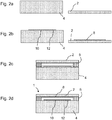
- Fign. 2a - 2d:
- eine Folge von Präparationsschritten zur Herstellung einer erfindungsgemäßen Druckmesszelle.
- Die in
Fig. 1 dargestellte Druckmesszelle 1 umfasst eine Messmembran 2, welche hochreines (>99,9%) Aluminiumoxid aufweist, und einen Gegenkörper 4, der ebenfalls Aluminiumoxid aufweist. Der Gegenkörper 4 kann die gleiche Reinheit wie die Messmembran aufweisen, wobei dies nicht zwingend erforderlich ist, da der Gegenkörper einerseits nicht medienberührend ist, so dass die Anforderungen an die Korrosionsbeständigkeit geringer sind und andererseits nicht den mechanischen Spannungen wie die Messmembran 2 ausgesetzt ist. Die Messmembran ist entlang einer umlaufenden Fügestelle 6, welche ein Zr-Ni-Ti-haltiges Aktivlot aufweist, unter Bildung einer Druckkammer zwischen der Messmembran 2 und dem Gegenkörper 4 druckdicht mit dem Gegenkörper verbunden. - Zum Erfassen einer druckabhängigen Verformung der Messmembran umfasst die Druckmesszelle 1 einen Differentialkondensator, der durch eine an der Messmembran 2 angeordnete Membranelektrode 8, eine zentrale gegenkörperseitige, kreisscheibenförmige Messelektrode 10 und eine, die Messelektrode umgebende Referenzelektrode 12 gebildet wird. Im Idealfall ist die Kapazitätzwischen der Messelektrode 10 und der Membranelektrode 8 gleich der Kapazität zwischen der Referenzelektrode 12 und der Membranelektrode 8, wenn sich die Messmembran 2 in der Ruhelage befindet. Die Membranelektrode 8 weist Titanoxid auf, welches unmittelbar auf dem keramischen Material der Messmembran 2 präpariert ist.
- Das Titanoxid enthält vorzugsweise eine Dotierung mit einigen Atom-% Nb, wodurch die Leitfähigkeit des Elektrodenmaterials erheblich verbessert wird.
- Die Referenzelektrode 12 und die Messelektrode 10 können einerseits ebenfalls Titanoxid aufweisen, welches ggf. dotiert ist, oder andererseits Platin bzw. Tantal. Sofern Tantalelektroden verwendet werden, sind diese vorzugsweise durch thermische Oxidation zu stabilisieren.
- Die Membranelektrode 8 wird über die Fügestelle 6 und eine elektrische Durchführung 20, die sich im radialen Bereich der Fügestelle 6 durch den Gegenkörper erstreckt, elektrisch kontaktiert. Die Messelektrode 10 und die Referenzelektrode 12 sind direkt über elektrische Durchführungen 22, 24 durch den Gegenkörper 4 kontaktiert. Die elektrischen Durchführungen 20, 22, 24 umfassen beispielsweise Tantalstifte, welche mittels eines Aktivhartlots druckdicht in Bohrungen durch den Gegenkörper 4 eingelötet sind.
- Die Membranelektrode 8, wirkt zugleich als Lotstopp, welches verhindert, das Aktivhartlot beim Verlöten von Gegenkörper 4 und Messmembran 2 daran gehindert wird, aus dem Randbereich radial einwärts in die Druckkammer zu fließen.
- Anhand von
Fign. 2a bis 2d werden nun kurz die Fertigungsschritte zum Herstellen der erfindungsgemäßen Druckmesszelle erläutert. - Zunächst werden, wie in
Fig. 2 a dargestellt, eine kreisscheibenförmige Messmembran 2 aus hochreinem Korund und ein steiferer, kreisplattenförmiger Gegenkörper 4 aus Korund bereitgestellt. - Anschließend werden, wie in
Fig. 2b dargestellt, auf dem Gegenkörper 4 und der Messmembran 2, die Flächen der Membranelektrode 8, der Messelektrode 10 und der Referenzelektrode 12 präpariert. - Die Membranelektrode 8 und ggf. weitere Elektroden auf Basis von Titanoxid umfasst bzw. umfassen hoch oxidiertes Titan, beispielsweise TiO2 und/oder Ti4O7, welches durch Sputtern von Titan und ggf. Dotierungsmetallen (Cr, Nb, W) auf das keramische Material der Messmembran 2 bzw. des Gegenkörpers 4 und anschließende thermische Oxidation bei 600°C an Luft präpariert wird.
- In einer alternativen Präparationsweise kann anstelle des metallischen Titans durch reaktives Sputtern kann unmittelbar Titanoxid abgeschieden werden, wodurch der anschließende Oxidationsschritt entfallen kann.
- Zum Vorbereiten des Fügens der Messmembran 2 mit dem Gegenkörper 4 werden die beiden Fügepartner mit einem ringförmigen Lotformteil 5 dazwischen koaxial gestapelt, wie in
Fig. 2c dargestellt ist. Das ringförmige Lotformteil 5 hat beispielsweise eine Höhe von etwa 30 µm bis 50 µm. - Abschließend werden die Komponenten in einem Hochvakuumlötprozess bei Temperaturen beispielsweise 950 °C gelötet, wobei das aufgeschmolzene Aktivhartlot mit den keramischen Oberflächen der Messmembran 2 und des Gegenkörpers 4 reagiert, allerdings kann es nicht über den Rand der Membranelektrode 8 in die Druckkammer einfließen, da der Sauerstoff aus dem Titanoxid zumindest teilweise in das Lot gelangt und damit das Lot verschlackt, so dass es erstarrt oder hochviskos wird und nicht weiter in die Druckkammer einfließt. Dennoch kommt es zu einem galvanischen Kontakt zwischen der Fügestelle 6 und der Membranelektrode 8, so dass über die Fügestelle eine metallische Beschichtung auf einer Mantelfläche der Druckmesszelle in Kontakt mit der Membranelektrode 8 gebracht werden kann.
- Im Ergebnis führt dies zu der in
Fig. 2d dargestellten Druckmesszelle. - Selbstverständlich umfasst auch diese die im Zusammenhang mit
Fig. 1 beschriebenen elektrischen Durchführungen, die jedoch inFign. 2a bis 2d im Sinne der Übersichtlichkeit weggelassen wurden. Die Durchführungen werden ebenfalls in dem Hochvakuumlötprozess eingelötet. - Insbesondere bei den Höhenverhältnissen wurde in den Zeichnungen auf Maßstabstreue verzichtet, um insbesondere die Schichten überhaupt darstellen zu können. Die radiale Größe der Druckmesszelle beträgt einige 10 mm. Die Höhe bzw. axiale Stärke des Gegenkörpers beträgt beispielsweise 3 bis 15 mm. Die Stärke der Messmembran beträgt beispielsweise nicht weniger 100 µm und beispielsweise nicht mehr als 2000 µm. Die Schichtdicke der Elektroden beträgt etwa 100 nm. Die Dimensionsangaben dienen lediglich zur Erläuterung und sind zur Definition oder einschränkenden Auslegung der Erfindung nicht heranzuziehen.
Claims (15)
- Druckmesszelle (1), aufweisend:eine keramische Messmembran (2); undeinen keramischen Gegenkörper (4),wobei die Messmembran (2) mit dem Gegenkörper (4) unter Bildung einer Druckkammer zwischen der Messmembran und dem Gegenkörper druckdicht gefügt ist, wobei die Messmembran eine der Druckkammer zugewandte Seite und eine der Druckkammer abgewandte Seite aufweist,wobei die Druckmesszelle (1) weiterhin einen kapazitiven Wandler zum Erfassen einer druckabhängigen Verformung der Messmembran (2) aufweist, welcher mindestens eine an der Messmembran angeordnete Membranelektrode (8) und mindestens eine gegenkörperseitige Elektrode (10, 12) aufweist,wobei die Membranelektrode (8) an der der Druckkammer zugewandten Seite der Messmembran (2) angeordnet ist,dadurch gekennzeichnet,dass mindestens die eine Membranelektrode (2) ein Titanoxid aufweist.
- Druckmesszelle (1) nach Anspruch 1, wobei das Titanoxid unmittelbar auf dem keramischen Material der Messmembran (2) angeordnet ist.
- Druckmesszelle (1) nach Anspruch 1 oder 2, wobei die Membranelektrode (8) Titanoxid aufweist, welches nichtstöchiometrisch ist.
- Druckmesszelle (1) nach Anspruch 3, wobei die Membranelektrode (8) nichtstöchiometrische Formen von TiO2,Ti4O7, Ti5O9 oder Ti6O11 aufweist.
- Druckmesszelle (1) nach einem der vorhergehenden Ansprüche, wobei die Membranelektrode (8) dotiertes Titanoxid aufweist.
- Druckmesszelle (1) nach Anspruch 5,
wobei das Titanoxid mit Cr, Nb oder W dotiert ist. - Druckmesszelle (1) nach Anspruch 5 oder 6,
wobei die Dotierung bis zu etwa 8 Atom-% bezogen auf die Ti Atome beträgt. - Druckmesszelle (1) nach einem der vorhergehenden Ansprüche,
wobei die Messmembran (2) mittels eines Aktivhartlots (6) mit dem Grundkörper (4) gefügt ist,
wobei die Membranelektrode (8) mit dem Aktivhartlot (6) im galvanischen Kontakt steht. - Druckmesszelle (1) nach einem der vorhergehenden Ansprüche,
wobei die Messmembran (2) und der Gegenkörper (4) eine Aluminiumoxidkeramik aufweisen. - Druckmesszelle (1) nach einem der Ansprüche 8 oder 9,
wobei das Aktivhartlot (6) ein Zirkon-Nickel-Titan-haltiges Aktivhartlot umfasst. - Verfahren zum Herstellen einer kapazitiven Druckmesszelle nach einem der Ansprüche 1-10, wobei das Verfahren die folgenden Schritte aufweist:• Bereitstellen der keramischen Messmembran (2) und des Gegenkörpers (4)• Präparieren mindestens der membranseitigen Elektrode (8) auf der Messmembran (2) und mindestens der gegenkörperseitigen Elektrode (10, 12) auf einer Oberfläche des Gegenkörpers (4);• druckdichtes Fügen der Messmembran mit dem Gegenkörper unter Bildung der Druckkammer zwischen der Messmembran (2) und dem Gegenkörper (4).
- Verfahren nach Anspruch 11,
wobei die Membranelektrode (8) präpariert wird, indem die Titanschicht bzw. die dotierte Titanschicht gesputtert wird, die anschließend thermisch oxidiert wird. - Verfahren nach Anspruch 12,
wobei die Oxidation durch Erhitzen in einer sauerstoffhaltigen Atmosphäre auf eine Temperatur von nicht weniger als 600°C erfolgt. - Verfahren nach Anspruch 11,
wobei die Membranelektrode durch reaktives Sputtern von Titanoxid präpariert wird. - Verfahren nach Anspruch 14,
wobei das Titanoxid mit Cr, Nb, und/oder W dotiert ist.
Applications Claiming Priority (2)
| Application Number | Priority Date | Filing Date | Title |
|---|---|---|---|
| DE102013106045.5A DE102013106045A1 (de) | 2013-06-11 | 2013-06-11 | Kapazitive, keramische Druckmesszelle und Verfahren zu ihrer Herstellung |
| PCT/EP2014/060186 WO2014198490A1 (de) | 2013-06-11 | 2014-05-19 | Kapazitive, keramische druckmesszelle und verfahren zu ihrer herstellung |
Publications (2)
| Publication Number | Publication Date |
|---|---|
| EP3008440A1 EP3008440A1 (de) | 2016-04-20 |
| EP3008440B1 true EP3008440B1 (de) | 2017-11-29 |
Family
ID=50732198
Family Applications (1)
| Application Number | Title | Priority Date | Filing Date |
|---|---|---|---|
| EP14724476.8A Active EP3008440B1 (de) | 2013-06-11 | 2014-05-19 | Kapazitive, keramische druckmesszelle und verfahren zu ihrer herstellung |
Country Status (5)
| Country | Link |
|---|---|
| US (1) | US9958350B2 (de) |
| EP (1) | EP3008440B1 (de) |
| CN (1) | CN105308426B (de) |
| DE (1) | DE102013106045A1 (de) |
| WO (1) | WO2014198490A1 (de) |
Families Citing this family (12)
| Publication number | Priority date | Publication date | Assignee | Title |
|---|---|---|---|---|
| DE102013113843A1 (de) * | 2013-12-11 | 2015-06-11 | Endress + Hauser Gmbh + Co. Kg | Drucksensor |
| DE102014113958A1 (de) * | 2014-09-26 | 2016-03-31 | Endress + Hauser Gmbh + Co. Kg | Verfahren zum Herstellen einer Verbindung zwischen zwei Keramikteilen, insbesondere von Teilen eines Drucksensors |
| DE102014117911A1 (de) * | 2014-12-04 | 2016-06-09 | Endress + Hauser Gmbh + Co. Kg | Druckmesszelle |
| DE102015105057A1 (de) | 2015-04-01 | 2016-10-06 | Endress + Hauser Gmbh + Co. Kg | Kapazitiver Drucksensor |
| DE102015122220A1 (de) * | 2015-12-18 | 2017-06-22 | Endress + Hauser Gmbh + Co. Kg | Keramische Druckmesszelle mit mindestens einem Temperaturmesswandler und Druckmessaufnehmer mit einer solchen Druckmesszelle |
| DE102016104760A1 (de) | 2015-12-22 | 2017-06-22 | Endress + Hauser Gmbh + Co. Kg | Druckmesseinrichtung |
| DE102016102775A1 (de) | 2016-02-17 | 2017-08-17 | Endress+Hauser Gmbh+Co. Kg | Kapazitiver Drucksensor |
| CN105859257A (zh) * | 2016-03-24 | 2016-08-17 | 长沙友创陶瓷科技有限公司 | 一种汽车发动机油压传感器陶瓷基座及加工工艺 |
| DE102017114299A1 (de) * | 2017-06-28 | 2019-01-03 | Endress+Hauser SE+Co. KG | Verfahren zur Herstellung einer Druckmesseinrichtung |
| DE102018114300A1 (de) | 2018-06-14 | 2019-12-19 | Endress+Hauser SE+Co. KG | Druckmesseinrichtung und Verfahren zu deren Herstellung |
| CN111220320B (zh) * | 2020-03-03 | 2025-08-01 | 中科九微科技股份有限公司 | 陶瓷电极、具有其的薄膜传感器及该陶瓷电极的制作方法 |
| DE102022110245B3 (de) * | 2022-04-27 | 2023-05-04 | Ifm Electronic Gmbh | Verfahren zur Erkennung von Belägen und/oder Anhaftungen an der Außenseite einer Messmembran eines Druckmessgeräts |
Citations (1)
| Publication number | Priority date | Publication date | Assignee | Title |
|---|---|---|---|---|
| JP2002214059A (ja) * | 2001-01-18 | 2002-07-31 | Teijin Seiki Co Ltd | シリコンダイアフラムを有する静電容量型真空計 |
Family Cites Families (15)
| Publication number | Priority date | Publication date | Assignee | Title |
|---|---|---|---|---|
| JPS6089573A (ja) | 1983-10-20 | 1985-05-20 | Ricoh Co Ltd | 透明導電膜 |
| IT1208128B (it) * | 1984-11-07 | 1989-06-06 | Alberto Pellegri | Elettrodo per uso in celle elettrochimiche, procedimento per la sua preparazione ed uso nell'elettrolisi del cloruro disodio. |
| DE3910646A1 (de) * | 1989-04-01 | 1990-10-04 | Endress Hauser Gmbh Co | Kapazitiver drucksensor und verfahren zu seiner herstellung |
| DE4129414A1 (de) | 1990-11-13 | 1993-03-11 | Endress Hauser Gmbh Co | Verwendung eines speziellen tiegels beim melt-spinning einer aktivlot-legierung |
| EP0544934B1 (de) | 1991-11-30 | 1996-10-02 | Endress U. Hauser Gmbh U. Co. | Verfahren zum Stabilisieren der Oberflächeneigenschaften von in Vakuum temperaturzubehandelnden Gegenständen |
| US6267009B1 (en) * | 1998-12-14 | 2001-07-31 | Endress + Hauser Gmbh + Co. | Capacitive pressure sensor cells or differential pressure sensor cells and methods for manufacturing the same |
| DE10114665A1 (de) | 2001-03-23 | 2002-09-26 | Bernhard Trier | Drucksensor mit Membran |
| US20070218646A1 (en) * | 2006-03-20 | 2007-09-20 | Asahi Glass Company, Limited | Process for producing electric conductor |
| DE102006056172A1 (de) * | 2006-11-27 | 2008-05-29 | Endress + Hauser Gmbh + Co. Kg | Elastischer Keramikkörper und Drucksensor mit einem elastischen Keramikkörper |
| DE102007026243A1 (de) | 2007-06-04 | 2008-12-11 | Endress + Hauser Gmbh + Co. Kg | Kapazitiver Drucksensor |
| TWI362488B (en) | 2008-02-13 | 2012-04-21 | Ind Tech Res Inst | Transistor type pressure sensor and method for making the same |
| DE102008036381B3 (de) | 2008-08-05 | 2010-04-22 | Endress + Hauser Gmbh + Co. Kg | Membran aus Al2O3- Keramik für einen Drucksensor und Drucksensor mit einer solchen Messmembran |
| DE102010043119A1 (de) | 2010-10-29 | 2012-05-03 | Endress + Hauser Gmbh + Co. Kg | Verfahren zum Herstellen einer Verbindung zwischen zwei Keramikteilen, insbesondere von Teilen eines Drucksensors, und ein keramisches Produkt, insbesondere einen keramischen Drucksensor |
| CN102455234B (zh) * | 2010-11-01 | 2014-04-30 | 香港纺织及成衣研发中心 | 薄膜型风压传感器及相应的无线传感网络 |
| DE102013105132A1 (de) * | 2013-05-17 | 2014-11-20 | Endress + Hauser Gmbh + Co. Kg | Keramische Druckmesszelle und Verfahren zu ihrer Herstellung |
-
2013
- 2013-06-11 DE DE102013106045.5A patent/DE102013106045A1/de not_active Withdrawn
-
2014
- 2014-05-19 US US14/896,470 patent/US9958350B2/en active Active
- 2014-05-19 EP EP14724476.8A patent/EP3008440B1/de active Active
- 2014-05-19 CN CN201480030137.XA patent/CN105308426B/zh active Active
- 2014-05-19 WO PCT/EP2014/060186 patent/WO2014198490A1/de not_active Ceased
Patent Citations (1)
| Publication number | Priority date | Publication date | Assignee | Title |
|---|---|---|---|---|
| JP2002214059A (ja) * | 2001-01-18 | 2002-07-31 | Teijin Seiki Co Ltd | シリコンダイアフラムを有する静電容量型真空計 |
Also Published As
| Publication number | Publication date |
|---|---|
| DE102013106045A8 (de) | 2015-02-19 |
| WO2014198490A1 (de) | 2014-12-18 |
| US20160131546A1 (en) | 2016-05-12 |
| CN105308426B (zh) | 2018-01-19 |
| US9958350B2 (en) | 2018-05-01 |
| CN105308426A (zh) | 2016-02-03 |
| EP3008440A1 (de) | 2016-04-20 |
| DE102013106045A1 (de) | 2014-12-11 |
Similar Documents
| Publication | Publication Date | Title |
|---|---|---|
| EP3008440B1 (de) | Kapazitive, keramische druckmesszelle und verfahren zu ihrer herstellung | |
| EP2162714B1 (de) | Kapazitiver drucksensor | |
| DE112011101480B4 (de) | Temperatursensor mit einem wärmeempfindlichen Bauteil | |
| EP0445382B1 (de) | Drucksensor und dessen Herstellverfahren | |
| EP3134374B1 (de) | Drucksensor mit einem keramischen grundkörper | |
| EP2454574B1 (de) | Kapazitive keramische druckmesszelle und drucksensor mit einer solchen druckmesszelle | |
| EP2872279B1 (de) | Verfahren zum fügen von keramikkörpern mittels eines aktivhartlots unter verwendung eines lotstopps, baugruppe mit mindestens zwei miteinander gefügten keramikkörpern, insbesondere druckmesszelle | |
| EP2917712B1 (de) | Temperaturfühler und verfahren zur herstellung eines temperaturfühlers | |
| WO2014183960A1 (de) | Keramische druckmesszelle und verfahren zu ihrer herstellung | |
| EP1040333A1 (de) | Membrane für eine kapazitive vakuummesszelle | |
| EP2513622B1 (de) | Keramisches produkt und verfahren zu dessen herstellung | |
| DE102009003178A1 (de) | Keramisches Bauteil mit mindestens einer elektrischen Durchführung, Verfahren zu dessen Herstellung und Drucksensor mit einem solchen Bauteil | |
| DE102007030910A1 (de) | Drucksensor | |
| EP3304019B1 (de) | Drucksensor mit einer aktivhartlötung | |
| DE102012103166B4 (de) | Druckmesszelle und Verfahren zu ihrer Herstellung | |
| DE102018108743A1 (de) | Drucksensor | |
| DE102015105057A1 (de) | Kapazitiver Drucksensor | |
| DE102014104506A1 (de) | Drucksensor | |
| DE102014103142A1 (de) | Druckmessaufnehmer | |
| EP0332978A1 (de) | Ni-Zr-Lötfolie | |
| DE102010003145A1 (de) | Drucksensor | |
| DE102007011878A1 (de) | Isolatorschichtsystem für einen Sensor und Sensor mit einem solchen Isolatorschichtsystem | |
| DE102010030156A1 (de) | Keramischer Drucksensor | |
| EP0988919A1 (de) | Siebdruck- oder dispensierfähige Aktivhartlotpasten und Verfahren zu deren Herstellung | |
| DE102016102775A1 (de) | Kapazitiver Drucksensor |
Legal Events
| Date | Code | Title | Description |
|---|---|---|---|
| PUAI | Public reference made under article 153(3) epc to a published international application that has entered the european phase |
Free format text: ORIGINAL CODE: 0009012 |
|
| 17P | Request for examination filed |
Effective date: 20151103 |
|
| AK | Designated contracting states |
Kind code of ref document: A1 Designated state(s): AL AT BE BG CH CY CZ DE DK EE ES FI FR GB GR HR HU IE IS IT LI LT LU LV MC MK MT NL NO PL PT RO RS SE SI SK SM TR |
|
| AX | Request for extension of the european patent |
Extension state: BA ME |
|
| RIN1 | Information on inventor provided before grant (corrected) |
Inventor name: ROSSBERG, ANDREAS Inventor name: PONATH, NILS |
|
| RIN1 | Information on inventor provided before grant (corrected) |
Inventor name: PONATH, NILS Inventor name: ROSSBERG, ANDREAS |
|
| DAX | Request for extension of the european patent (deleted) | ||
| 17Q | First examination report despatched |
Effective date: 20161014 |
|
| REG | Reference to a national code |
Ref country code: DE Ref legal event code: R079 Ref document number: 502014006405 Country of ref document: DE Free format text: PREVIOUS MAIN CLASS: G01L0009000000 Ipc: B23K0001000000 |
|
| GRAP | Despatch of communication of intention to grant a patent |
Free format text: ORIGINAL CODE: EPIDOSNIGR1 |
|
| RIC1 | Information provided on ipc code assigned before grant |
Ipc: B23K 1/00 20060101AFI20170626BHEP Ipc: G01L 19/00 20060101ALI20170626BHEP Ipc: B23K 103/00 20060101ALI20170626BHEP Ipc: C23C 8/16 20060101ALI20170626BHEP Ipc: C23C 14/00 20060101ALI20170626BHEP Ipc: B23K 1/19 20060101ALI20170626BHEP Ipc: G01L 9/00 20060101ALI20170626BHEP Ipc: C23C 14/34 20060101ALI20170626BHEP Ipc: C23C 14/14 20060101ALI20170626BHEP |
|
| INTG | Intention to grant announced |
Effective date: 20170718 |
|
| GRAS | Grant fee paid |
Free format text: ORIGINAL CODE: EPIDOSNIGR3 |
|
| GRAA | (expected) grant |
Free format text: ORIGINAL CODE: 0009210 |
|
| AK | Designated contracting states |
Kind code of ref document: B1 Designated state(s): AL AT BE BG CH CY CZ DE DK EE ES FI FR GB GR HR HU IE IS IT LI LT LU LV MC MK MT NL NO PL PT RO RS SE SI SK SM TR |
|
| REG | Reference to a national code |
Ref country code: CH Ref legal event code: EP |
|
| REG | Reference to a national code |
Ref country code: AT Ref legal event code: REF Ref document number: 949940 Country of ref document: AT Kind code of ref document: T Effective date: 20171215 |
|
| REG | Reference to a national code |
Ref country code: IE Ref legal event code: FG4D Free format text: LANGUAGE OF EP DOCUMENT: GERMAN |
|
| REG | Reference to a national code |
Ref country code: DE Ref legal event code: R096 Ref document number: 502014006405 Country of ref document: DE |
|
| REG | Reference to a national code |
Ref country code: DE Ref legal event code: R081 Ref document number: 502014006405 Country of ref document: DE Owner name: ENDRESS+HAUSER SE+CO. KG, DE Free format text: FORMER OWNER: ENDRESS+HAUSER GMBH+CO. KG, 79689 MAULBURG, DE |
|
| REG | Reference to a national code |
Ref country code: NL Ref legal event code: MP Effective date: 20171129 |
|
| REG | Reference to a national code |
Ref country code: LT Ref legal event code: MG4D |
|
| RAP2 | Party data changed (patent owner data changed or rights of a patent transferred) |
Owner name: ENDRESS+HAUSER SE+CO. KG |
|
| PG25 | Lapsed in a contracting state [announced via postgrant information from national office to epo] |
Ref country code: FI Free format text: LAPSE BECAUSE OF FAILURE TO SUBMIT A TRANSLATION OF THE DESCRIPTION OR TO PAY THE FEE WITHIN THE PRESCRIBED TIME-LIMIT Effective date: 20171129 Ref country code: NO Free format text: LAPSE BECAUSE OF FAILURE TO SUBMIT A TRANSLATION OF THE DESCRIPTION OR TO PAY THE FEE WITHIN THE PRESCRIBED TIME-LIMIT Effective date: 20180228 Ref country code: LT Free format text: LAPSE BECAUSE OF FAILURE TO SUBMIT A TRANSLATION OF THE DESCRIPTION OR TO PAY THE FEE WITHIN THE PRESCRIBED TIME-LIMIT Effective date: 20171129 Ref country code: ES Free format text: LAPSE BECAUSE OF FAILURE TO SUBMIT A TRANSLATION OF THE DESCRIPTION OR TO PAY THE FEE WITHIN THE PRESCRIBED TIME-LIMIT Effective date: 20171129 Ref country code: SE Free format text: LAPSE BECAUSE OF FAILURE TO SUBMIT A TRANSLATION OF THE DESCRIPTION OR TO PAY THE FEE WITHIN THE PRESCRIBED TIME-LIMIT Effective date: 20171129 |
|
| REG | Reference to a national code |
Ref country code: FR Ref legal event code: PLFP Year of fee payment: 5 |
|
| PG25 | Lapsed in a contracting state [announced via postgrant information from national office to epo] |
Ref country code: GR Free format text: LAPSE BECAUSE OF FAILURE TO SUBMIT A TRANSLATION OF THE DESCRIPTION OR TO PAY THE FEE WITHIN THE PRESCRIBED TIME-LIMIT Effective date: 20180301 Ref country code: LV Free format text: LAPSE BECAUSE OF FAILURE TO SUBMIT A TRANSLATION OF THE DESCRIPTION OR TO PAY THE FEE WITHIN THE PRESCRIBED TIME-LIMIT Effective date: 20171129 Ref country code: HR Free format text: LAPSE BECAUSE OF FAILURE TO SUBMIT A TRANSLATION OF THE DESCRIPTION OR TO PAY THE FEE WITHIN THE PRESCRIBED TIME-LIMIT Effective date: 20171129 Ref country code: RS Free format text: LAPSE BECAUSE OF FAILURE TO SUBMIT A TRANSLATION OF THE DESCRIPTION OR TO PAY THE FEE WITHIN THE PRESCRIBED TIME-LIMIT Effective date: 20171129 Ref country code: BG Free format text: LAPSE BECAUSE OF FAILURE TO SUBMIT A TRANSLATION OF THE DESCRIPTION OR TO PAY THE FEE WITHIN THE PRESCRIBED TIME-LIMIT Effective date: 20180228 |
|
| PG25 | Lapsed in a contracting state [announced via postgrant information from national office to epo] |
Ref country code: NL Free format text: LAPSE BECAUSE OF FAILURE TO SUBMIT A TRANSLATION OF THE DESCRIPTION OR TO PAY THE FEE WITHIN THE PRESCRIBED TIME-LIMIT Effective date: 20171129 |
|
| PG25 | Lapsed in a contracting state [announced via postgrant information from national office to epo] |
Ref country code: DK Free format text: LAPSE BECAUSE OF FAILURE TO SUBMIT A TRANSLATION OF THE DESCRIPTION OR TO PAY THE FEE WITHIN THE PRESCRIBED TIME-LIMIT Effective date: 20171129 Ref country code: SK Free format text: LAPSE BECAUSE OF FAILURE TO SUBMIT A TRANSLATION OF THE DESCRIPTION OR TO PAY THE FEE WITHIN THE PRESCRIBED TIME-LIMIT Effective date: 20171129 Ref country code: CZ Free format text: LAPSE BECAUSE OF FAILURE TO SUBMIT A TRANSLATION OF THE DESCRIPTION OR TO PAY THE FEE WITHIN THE PRESCRIBED TIME-LIMIT Effective date: 20171129 Ref country code: EE Free format text: LAPSE BECAUSE OF FAILURE TO SUBMIT A TRANSLATION OF THE DESCRIPTION OR TO PAY THE FEE WITHIN THE PRESCRIBED TIME-LIMIT Effective date: 20171129 Ref country code: CY Free format text: LAPSE BECAUSE OF FAILURE TO SUBMIT A TRANSLATION OF THE DESCRIPTION OR TO PAY THE FEE WITHIN THE PRESCRIBED TIME-LIMIT Effective date: 20171129 |
|
| REG | Reference to a national code |
Ref country code: DE Ref legal event code: R097 Ref document number: 502014006405 Country of ref document: DE |
|
| PG25 | Lapsed in a contracting state [announced via postgrant information from national office to epo] |
Ref country code: PL Free format text: LAPSE BECAUSE OF FAILURE TO SUBMIT A TRANSLATION OF THE DESCRIPTION OR TO PAY THE FEE WITHIN THE PRESCRIBED TIME-LIMIT Effective date: 20171129 Ref country code: RO Free format text: LAPSE BECAUSE OF FAILURE TO SUBMIT A TRANSLATION OF THE DESCRIPTION OR TO PAY THE FEE WITHIN THE PRESCRIBED TIME-LIMIT Effective date: 20171129 Ref country code: SM Free format text: LAPSE BECAUSE OF FAILURE TO SUBMIT A TRANSLATION OF THE DESCRIPTION OR TO PAY THE FEE WITHIN THE PRESCRIBED TIME-LIMIT Effective date: 20171129 |
|
| PG25 | Lapsed in a contracting state [announced via postgrant information from national office to epo] |
Ref country code: MT Free format text: LAPSE BECAUSE OF FAILURE TO SUBMIT A TRANSLATION OF THE DESCRIPTION OR TO PAY THE FEE WITHIN THE PRESCRIBED TIME-LIMIT Effective date: 20171129 |
|
| PLBE | No opposition filed within time limit |
Free format text: ORIGINAL CODE: 0009261 |
|
| STAA | Information on the status of an ep patent application or granted ep patent |
Free format text: STATUS: NO OPPOSITION FILED WITHIN TIME LIMIT |
|
| 26N | No opposition filed |
Effective date: 20180830 |
|
| PG25 | Lapsed in a contracting state [announced via postgrant information from national office to epo] |
Ref country code: SI Free format text: LAPSE BECAUSE OF FAILURE TO SUBMIT A TRANSLATION OF THE DESCRIPTION OR TO PAY THE FEE WITHIN THE PRESCRIBED TIME-LIMIT Effective date: 20171129 |
|
| REG | Reference to a national code |
Ref country code: CH Ref legal event code: PL |
|
| REG | Reference to a national code |
Ref country code: BE Ref legal event code: MM Effective date: 20180531 |
|
| PG25 | Lapsed in a contracting state [announced via postgrant information from national office to epo] |
Ref country code: MC Free format text: LAPSE BECAUSE OF FAILURE TO SUBMIT A TRANSLATION OF THE DESCRIPTION OR TO PAY THE FEE WITHIN THE PRESCRIBED TIME-LIMIT Effective date: 20171129 |
|
| REG | Reference to a national code |
Ref country code: IE Ref legal event code: MM4A |
|
| PG25 | Lapsed in a contracting state [announced via postgrant information from national office to epo] |
Ref country code: CH Free format text: LAPSE BECAUSE OF NON-PAYMENT OF DUE FEES Effective date: 20180531 Ref country code: LI Free format text: LAPSE BECAUSE OF NON-PAYMENT OF DUE FEES Effective date: 20180531 |
|
| PG25 | Lapsed in a contracting state [announced via postgrant information from national office to epo] |
Ref country code: LU Free format text: LAPSE BECAUSE OF NON-PAYMENT OF DUE FEES Effective date: 20180519 |
|
| PG25 | Lapsed in a contracting state [announced via postgrant information from national office to epo] |
Ref country code: IE Free format text: LAPSE BECAUSE OF NON-PAYMENT OF DUE FEES Effective date: 20180519 |
|
| PG25 | Lapsed in a contracting state [announced via postgrant information from national office to epo] |
Ref country code: BE Free format text: LAPSE BECAUSE OF NON-PAYMENT OF DUE FEES Effective date: 20180531 |
|
| PG25 | Lapsed in a contracting state [announced via postgrant information from national office to epo] |
Ref country code: TR Free format text: LAPSE BECAUSE OF FAILURE TO SUBMIT A TRANSLATION OF THE DESCRIPTION OR TO PAY THE FEE WITHIN THE PRESCRIBED TIME-LIMIT Effective date: 20171129 |
|
| PG25 | Lapsed in a contracting state [announced via postgrant information from national office to epo] |
Ref country code: PT Free format text: LAPSE BECAUSE OF FAILURE TO SUBMIT A TRANSLATION OF THE DESCRIPTION OR TO PAY THE FEE WITHIN THE PRESCRIBED TIME-LIMIT Effective date: 20171129 |
|
| PG25 | Lapsed in a contracting state [announced via postgrant information from national office to epo] |
Ref country code: MK Free format text: LAPSE BECAUSE OF NON-PAYMENT OF DUE FEES Effective date: 20171129 Ref country code: HU Free format text: LAPSE BECAUSE OF FAILURE TO SUBMIT A TRANSLATION OF THE DESCRIPTION OR TO PAY THE FEE WITHIN THE PRESCRIBED TIME-LIMIT; INVALID AB INITIO Effective date: 20140519 |
|
| PG25 | Lapsed in a contracting state [announced via postgrant information from national office to epo] |
Ref country code: AL Free format text: LAPSE BECAUSE OF FAILURE TO SUBMIT A TRANSLATION OF THE DESCRIPTION OR TO PAY THE FEE WITHIN THE PRESCRIBED TIME-LIMIT Effective date: 20171129 Ref country code: IS Free format text: LAPSE BECAUSE OF FAILURE TO SUBMIT A TRANSLATION OF THE DESCRIPTION OR TO PAY THE FEE WITHIN THE PRESCRIBED TIME-LIMIT Effective date: 20180329 |
|
| REG | Reference to a national code |
Ref country code: AT Ref legal event code: MM01 Ref document number: 949940 Country of ref document: AT Kind code of ref document: T Effective date: 20190519 |
|
| PG25 | Lapsed in a contracting state [announced via postgrant information from national office to epo] |
Ref country code: AT Free format text: LAPSE BECAUSE OF NON-PAYMENT OF DUE FEES Effective date: 20190519 |
|
| P01 | Opt-out of the competence of the unified patent court (upc) registered |
Effective date: 20230601 |
|
| PGFP | Annual fee paid to national office [announced via postgrant information from national office to epo] |
Ref country code: GB Payment date: 20240521 Year of fee payment: 11 |
|
| PGFP | Annual fee paid to national office [announced via postgrant information from national office to epo] |
Ref country code: FR Payment date: 20240528 Year of fee payment: 11 |
|
| PGFP | Annual fee paid to national office [announced via postgrant information from national office to epo] |
Ref country code: IT Payment date: 20240524 Year of fee payment: 11 |
|
| PGFP | Annual fee paid to national office [announced via postgrant information from national office to epo] |
Ref country code: DE Payment date: 20250521 Year of fee payment: 12 |
|
| GBPC | Gb: european patent ceased through non-payment of renewal fee |
Effective date: 20250519 |
|
| PG25 | Lapsed in a contracting state [announced via postgrant information from national office to epo] |
Ref country code: GB Free format text: LAPSE BECAUSE OF NON-PAYMENT OF DUE FEES Effective date: 20250519 |
|
| PG25 | Lapsed in a contracting state [announced via postgrant information from national office to epo] |
Ref country code: IT Free format text: LAPSE BECAUSE OF NON-PAYMENT OF DUE FEES Effective date: 20250519 |
|
| PG25 | Lapsed in a contracting state [announced via postgrant information from national office to epo] |
Ref country code: FR Free format text: LAPSE BECAUSE OF NON-PAYMENT OF DUE FEES Effective date: 20250531 |