EP3009759B1 - Véhicule utilitaire - Google Patents
Véhicule utilitaire Download PDFInfo
- Publication number
- EP3009759B1 EP3009759B1 EP14720039.8A EP14720039A EP3009759B1 EP 3009759 B1 EP3009759 B1 EP 3009759B1 EP 14720039 A EP14720039 A EP 14720039A EP 3009759 B1 EP3009759 B1 EP 3009759B1
- Authority
- EP
- European Patent Office
- Prior art keywords
- duct body
- top plate
- end part
- body part
- compartment
- Prior art date
- Legal status (The legal status is an assumption and is not a legal conclusion. Google has not performed a legal analysis and makes no representation as to the accuracy of the status listed.)
- Not-in-force
Links
Images





Classifications
-
- E—FIXED CONSTRUCTIONS
- E02—HYDRAULIC ENGINEERING; FOUNDATIONS; SOIL SHIFTING
- E02F—DREDGING; SOIL-SHIFTING
- E02F9/00—Component parts of dredgers or soil-shifting machines, not restricted to one of the kinds covered by groups E02F3/00 - E02F7/00
- E02F9/08—Superstructures; Supports for superstructures
- E02F9/0858—Arrangement of component parts installed on superstructures not otherwise provided for, e.g. electric components, fenders, air-conditioning units
- E02F9/0866—Engine compartment, e.g. heat exchangers, exhaust filters, cooling devices, silencers, mufflers, position of hydraulic pumps in the engine compartment
-
- B—PERFORMING OPERATIONS; TRANSPORTING
- B60—VEHICLES IN GENERAL
- B60K—ARRANGEMENT OR MOUNTING OF PROPULSION UNITS OR OF TRANSMISSIONS IN VEHICLES; ARRANGEMENT OR MOUNTING OF PLURAL DIVERSE PRIME-MOVERS IN VEHICLES; AUXILIARY DRIVES FOR VEHICLES; INSTRUMENTATION OR DASHBOARDS FOR VEHICLES; ARRANGEMENTS IN CONNECTION WITH COOLING, AIR INTAKE, GAS EXHAUST OR FUEL SUPPLY OF PROPULSION UNITS IN VEHICLES
- B60K11/00—Arrangement in connection with cooling of propulsion units
- B60K11/02—Arrangement in connection with cooling of propulsion units with liquid cooling
-
- B—PERFORMING OPERATIONS; TRANSPORTING
- B60—VEHICLES IN GENERAL
- B60K—ARRANGEMENT OR MOUNTING OF PROPULSION UNITS OR OF TRANSMISSIONS IN VEHICLES; ARRANGEMENT OR MOUNTING OF PLURAL DIVERSE PRIME-MOVERS IN VEHICLES; AUXILIARY DRIVES FOR VEHICLES; INSTRUMENTATION OR DASHBOARDS FOR VEHICLES; ARRANGEMENTS IN CONNECTION WITH COOLING, AIR INTAKE, GAS EXHAUST OR FUEL SUPPLY OF PROPULSION UNITS IN VEHICLES
- B60K11/00—Arrangement in connection with cooling of propulsion units
- B60K11/06—Arrangement in connection with cooling of propulsion units with air cooling
-
- B—PERFORMING OPERATIONS; TRANSPORTING
- B60—VEHICLES IN GENERAL
- B60K—ARRANGEMENT OR MOUNTING OF PROPULSION UNITS OR OF TRANSMISSIONS IN VEHICLES; ARRANGEMENT OR MOUNTING OF PLURAL DIVERSE PRIME-MOVERS IN VEHICLES; AUXILIARY DRIVES FOR VEHICLES; INSTRUMENTATION OR DASHBOARDS FOR VEHICLES; ARRANGEMENTS IN CONNECTION WITH COOLING, AIR INTAKE, GAS EXHAUST OR FUEL SUPPLY OF PROPULSION UNITS IN VEHICLES
- B60K11/00—Arrangement in connection with cooling of propulsion units
- B60K11/08—Air inlets for cooling; Shutters or blinds therefor
-
- E—FIXED CONSTRUCTIONS
- E02—HYDRAULIC ENGINEERING; FOUNDATIONS; SOIL SHIFTING
- E02F—DREDGING; SOIL-SHIFTING
- E02F9/00—Component parts of dredgers or soil-shifting machines, not restricted to one of the kinds covered by groups E02F3/00 - E02F7/00
- E02F9/08—Superstructures; Supports for superstructures
- E02F9/0858—Arrangement of component parts installed on superstructures not otherwise provided for, e.g. electric components, fenders, air-conditioning units
- E02F9/0891—Lids or bonnets or doors or details thereof
-
- F—MECHANICAL ENGINEERING; LIGHTING; HEATING; WEAPONS; BLASTING
- F01—MACHINES OR ENGINES IN GENERAL; ENGINE PLANTS IN GENERAL; STEAM ENGINES
- F01P—COOLING OF MACHINES OR ENGINES IN GENERAL; COOLING OF INTERNAL-COMBUSTION ENGINES
- F01P1/00—Air cooling
- F01P1/06—Arrangements for cooling other engine or machine parts
-
- B—PERFORMING OPERATIONS; TRANSPORTING
- B60—VEHICLES IN GENERAL
- B60Y—INDEXING SCHEME RELATING TO ASPECTS CROSS-CUTTING VEHICLE TECHNOLOGY
- B60Y2200/00—Type of vehicle
- B60Y2200/40—Special vehicles
- B60Y2200/41—Construction vehicles, e.g. graders, excavators
- B60Y2200/415—Wheel loaders
-
- F—MECHANICAL ENGINEERING; LIGHTING; HEATING; WEAPONS; BLASTING
- F01—MACHINES OR ENGINES IN GENERAL; ENGINE PLANTS IN GENERAL; STEAM ENGINES
- F01N—GAS-FLOW SILENCERS OR EXHAUST APPARATUS FOR MACHINES OR ENGINES IN GENERAL; GAS-FLOW SILENCERS OR EXHAUST APPARATUS FOR INTERNAL-COMBUSTION ENGINES
- F01N13/00—Exhaust or silencing apparatus characterised by constructional features
- F01N13/008—Mounting or arrangement of exhaust sensors in or on exhaust apparatus
-
- F—MECHANICAL ENGINEERING; LIGHTING; HEATING; WEAPONS; BLASTING
- F01—MACHINES OR ENGINES IN GENERAL; ENGINE PLANTS IN GENERAL; STEAM ENGINES
- F01N—GAS-FLOW SILENCERS OR EXHAUST APPARATUS FOR MACHINES OR ENGINES IN GENERAL; GAS-FLOW SILENCERS OR EXHAUST APPARATUS FOR INTERNAL-COMBUSTION ENGINES
- F01N13/00—Exhaust or silencing apparatus characterised by constructional features
- F01N13/18—Construction facilitating manufacture, assembly, or disassembly
- F01N13/1805—Fixing exhaust manifolds, exhaust pipes or pipe sections to each other, to engine or to vehicle body
-
- F—MECHANICAL ENGINEERING; LIGHTING; HEATING; WEAPONS; BLASTING
- F01—MACHINES OR ENGINES IN GENERAL; ENGINE PLANTS IN GENERAL; STEAM ENGINES
- F01N—GAS-FLOW SILENCERS OR EXHAUST APPARATUS FOR MACHINES OR ENGINES IN GENERAL; GAS-FLOW SILENCERS OR EXHAUST APPARATUS FOR INTERNAL-COMBUSTION ENGINES
- F01N2260/00—Exhaust treating devices having provisions not otherwise provided for
- F01N2260/02—Exhaust treating devices having provisions not otherwise provided for for cooling the device
- F01N2260/022—Exhaust treating devices having provisions not otherwise provided for for cooling the device using air
-
- F—MECHANICAL ENGINEERING; LIGHTING; HEATING; WEAPONS; BLASTING
- F01—MACHINES OR ENGINES IN GENERAL; ENGINE PLANTS IN GENERAL; STEAM ENGINES
- F01N—GAS-FLOW SILENCERS OR EXHAUST APPARATUS FOR MACHINES OR ENGINES IN GENERAL; GAS-FLOW SILENCERS OR EXHAUST APPARATUS FOR INTERNAL-COMBUSTION ENGINES
- F01N2560/00—Exhaust systems with means for detecting or measuring exhaust gas components or characteristics
- F01N2560/02—Exhaust systems with means for detecting or measuring exhaust gas components or characteristics the means being an exhaust gas sensor
- F01N2560/026—Exhaust systems with means for detecting or measuring exhaust gas components or characteristics the means being an exhaust gas sensor for measuring or detecting NOx
-
- F—MECHANICAL ENGINEERING; LIGHTING; HEATING; WEAPONS; BLASTING
- F01—MACHINES OR ENGINES IN GENERAL; ENGINE PLANTS IN GENERAL; STEAM ENGINES
- F01N—GAS-FLOW SILENCERS OR EXHAUST APPARATUS FOR MACHINES OR ENGINES IN GENERAL; GAS-FLOW SILENCERS OR EXHAUST APPARATUS FOR INTERNAL-COMBUSTION ENGINES
- F01N2610/00—Adding substances to exhaust gases
- F01N2610/02—Adding substances to exhaust gases the substance being ammonia or urea
-
- F—MECHANICAL ENGINEERING; LIGHTING; HEATING; WEAPONS; BLASTING
- F01—MACHINES OR ENGINES IN GENERAL; ENGINE PLANTS IN GENERAL; STEAM ENGINES
- F01N—GAS-FLOW SILENCERS OR EXHAUST APPARATUS FOR MACHINES OR ENGINES IN GENERAL; GAS-FLOW SILENCERS OR EXHAUST APPARATUS FOR INTERNAL-COMBUSTION ENGINES
- F01N2610/00—Adding substances to exhaust gases
- F01N2610/11—Adding substances to exhaust gases the substance or part of the dosing system being cooled
-
- F—MECHANICAL ENGINEERING; LIGHTING; HEATING; WEAPONS; BLASTING
- F01—MACHINES OR ENGINES IN GENERAL; ENGINE PLANTS IN GENERAL; STEAM ENGINES
- F01N—GAS-FLOW SILENCERS OR EXHAUST APPARATUS FOR MACHINES OR ENGINES IN GENERAL; GAS-FLOW SILENCERS OR EXHAUST APPARATUS FOR INTERNAL-COMBUSTION ENGINES
- F01N3/00—Exhaust or silencing apparatus having means for purifying, rendering innocuous, or otherwise treating exhaust
- F01N3/08—Exhaust or silencing apparatus having means for purifying, rendering innocuous, or otherwise treating exhaust for rendering innocuous
- F01N3/10—Exhaust or silencing apparatus having means for purifying, rendering innocuous, or otherwise treating exhaust for rendering innocuous by thermal or catalytic conversion of noxious components of exhaust
- F01N3/18—Exhaust or silencing apparatus having means for purifying, rendering innocuous, or otherwise treating exhaust for rendering innocuous by thermal or catalytic conversion of noxious components of exhaust characterised by methods of operation; Control
- F01N3/20—Exhaust or silencing apparatus having means for purifying, rendering innocuous, or otherwise treating exhaust for rendering innocuous by thermal or catalytic conversion of noxious components of exhaust characterised by methods of operation; Control specially adapted for catalytic conversion
- F01N3/206—Adding periodically or continuously substances to exhaust gases for promoting purification, e.g. catalytic material in liquid form, NOx reducing agents
- F01N3/2066—Selective catalytic reduction [SCR]
-
- F—MECHANICAL ENGINEERING; LIGHTING; HEATING; WEAPONS; BLASTING
- F01—MACHINES OR ENGINES IN GENERAL; ENGINE PLANTS IN GENERAL; STEAM ENGINES
- F01P—COOLING OF MACHINES OR ENGINES IN GENERAL; COOLING OF INTERNAL-COMBUSTION ENGINES
- F01P1/00—Air cooling
- F01P2001/005—Cooling engine rooms
-
- Y—GENERAL TAGGING OF NEW TECHNOLOGICAL DEVELOPMENTS; GENERAL TAGGING OF CROSS-SECTIONAL TECHNOLOGIES SPANNING OVER SEVERAL SECTIONS OF THE IPC; TECHNICAL SUBJECTS COVERED BY FORMER USPC CROSS-REFERENCE ART COLLECTIONS [XRACs] AND DIGESTS
- Y02—TECHNOLOGIES OR APPLICATIONS FOR MITIGATION OR ADAPTATION AGAINST CLIMATE CHANGE
- Y02A—TECHNOLOGIES FOR ADAPTATION TO CLIMATE CHANGE
- Y02A50/00—TECHNOLOGIES FOR ADAPTATION TO CLIMATE CHANGE in human health protection, e.g. against extreme weather
- Y02A50/20—Air quality improvement or preservation, e.g. vehicle emission control or emission reduction by using catalytic converters
Definitions
- the present invention relates to a work vehicle.
- a work vehicle is provided with an engine compartment.
- An engine is contained inside the engine compartment.
- Various devices other than the engine are also contained inside the engine compartment.
- an exhaust gas post-processing device for processing exhaust gas from the engine is contained inside the engine compartment in the work vehicle disclosed in JP 2014-025254 .
- US 5 199 522 A refers to an air inlet arrangement for an engine of a vehicle such as a tractor.
- a plenum plate attached to an engine compartment cover is provided for sucking cool air from a location away from an engine to an air cleaner or filter.
- JP 2001 200771 A refers to a sound absorbing duct of a work machine.
- the sound absorbing duct is connected to an air cleaner of an engine.
- the sound absorbing duct has a ventilation member and a silencer component which are both attached to a ceiling part of an engine cover.
- JP 2007 283801 A refers to a wheel loader having an engine bay and a heat exchange room which are separated by a partition plate.
- a cooling fan is arranged in a shroud.
- JP 2012 136846 A describes ways how a coolant hose and an aftercooler hose can be fixed to a septum in an inclined way.
- the aftercooler hose is a hose which sends the air supply from the compressor of the exhaust turbo charger to an aftercooler.
- EP 2 384 954 A1 describes a bonnet structure of a working vehicle.
- An object of the present invention is to suppress an excessive rise in temperature inside the engine compartment.
- a work vehicle is provided with an engine compartment, a cooling compartment, a partition wall, a cooling fan, a top plate, and a first duct body part.
- the partition wall partitions the engine compartment from the cooling compartment.
- the cooling fan is contained in the cooling compartment and exhausts air from the cooling compartment.
- the top plate defines an upper surface of the engine compartment.
- the top plate is capable of being opened.
- the first duct body part has a first end part and a second end part. The first end part is positioned inside the engine compartment. The second end part is positioned inside the cooling compartment.
- the first duct body part is attached to the top plate.
- the first duct body part is configured to suck in air from the first end part and to exhaust the air from the second end part.
- the second end part of the first duct body part is positioned in the cooling compartment.
- the cooling compartment is a space with negative pressure when the cooling fan is operating.
- the first duct body part sucks in air from the first end part and exhausts the air from the second end part. Consequently, hot air inside the engine compartment is exhausted to the cooling compartment and an excessive rise in temperature inside the engine compartment can be suppressed. Since the inside of the engine compartment develops a negative pressure due to the hot air inside the engine compartment being exhausted to the cooling compartment, outdoor air flows into the engine compartment and the inside of the engine compartment can be cooled.
- the first duct body part is attached to the top plate.
- the first duct body part can be removed from the engine compartment at the same time that the top plate is opened for performing maintenance inside the engine compartment. That is, work to remove the first duct body part can be omitted. Consequently, workability when performing maintenance inside the engine compartment is improved.
- the top plate can be opened with various methods. For example, the top plate may be opened by completely removing the top plate from a vehicle frame. Further, the top plate may be attached to the vehicle frame in a manner that allows swinging and the top plate may be opened by swinging the top plate open. Specifically, the top plate is attached to the vehicle frame via a hinge and the top plate may be opened by swinging the top plate around the hinge.
- the work vehicle preferably is further provided with a first member to be cooled and a first intake part.
- the first member to be cooled is disposed inside the engine compartment.
- the first intake part extends from the first end part of the first duct body part toward the first member to be cooled.
- the first intake part is preferably attached in a removable manner to the first end part of the first duct body part. According to this configuration, the first intake part can be left inside the engine compartment when removing the top plate and the first duct body part. As a result, the first intake part can be disposed inside an intricate space inside the engine compartment. Consequently, even if the first member to be cooled is disposed in the intricate space, the first intake part can be extended to the vicinity of the first member to be cooled to enable cooling of the first member to be cooled.
- the work vehicle preferably is further provided with a second member to be cooled and a second intake part.
- the second member to be cooled is disposed inside the engine compartment.
- the second intake part extends from the first end part of the first duct body part toward the second member to be cooled. According to this configuration, even if the first member to be cooled and the second member to be cooled are disposed away from each other, both members to be cooled can be cooled.
- a flow passage area in the first duct body part is preferably larger than a flow passage area of the first intake part or larger than a flow passage area of the second intake part.
- the flow passage area of the first duct body part is more preferably is substantially equal to the combined surface areas of the flow passage area of the first intake part and the flow passage area of the second intake part.
- the top plate preferably has a top plate body part and leg parts.
- the top plate body part defines the upper surface of the engine compartment.
- the leg parts extend downward from the top plate body part.
- the lower end of the first duct body part is positioned above the lower end of the leg parts. According to this configuration, when the top plate is removed and placed on the ground, the first duct body part can be prevented from coming into contact with the ground.
- the partition wall preferably has a notch part in an upper end part.
- the first duct body part extends between the engine compartment and the cooling compartment via the notch part.
- the work vehicle is preferably further equipped with a second duct body part.
- the second duct body part has a third end part and a fourth end part.
- the third end part is positioned inside the engine compartment.
- the fourth end part is positioned inside the cooling compartment.
- the second duct body part is attached to the top plate.
- an excessive rise in temperature inside the engine compartment can be suppressed.
- FIG. 1 is a perspective external view of a wheel loader 100 as seen from the left rear.
- "right,” “left,” “up,” and “down” indicate directions relative to a state of looking forward from the driver's seat.
- "Vehicle width direction” and “crosswise direction” have the same meaning.
- the front-back direction signifies the front-back direction of the vehicle body.
- a wheel loader 100 includes a work implement 110, a vehicle body 120, front wheels 130, and rear wheels 140.
- the wheel loader 100 is capable of traveling due to the rotation of the front wheels 130 and the rear wheels 140, and desired work can be conducted using the work implement 110.
- the work implement 110 is a mechanism driven by operating fluid pressurized by a hydraulic pump, and is disposed at the front of the vehicle body 120.
- the work implement 110 includes a bucket 111, a boom (not shown), a lift cylinder (not shown), and a bucket cylinder 112.
- the bucket 111 is attached to the tip of the boom.
- the boom is a member for lifting the bucket 111 and is mounted at the front part of a belowmentioned front vehicle part 120a.
- the lift cylinder drives the boom with pressure oil discharged from a work implement pump.
- the bucket cylinder 112 drives the bucket 111 with pressure oil discharged from the work implement pump.
- the vehicle body 120 has the front vehicle part 120a and a rear vehicle part 120b.
- the front vehicle part 120a and the rear vehicle part 120b are connected to each other so as to allow swinging in the left-right direction.
- the work implement 110 and the front wheels 130 are provided on the front vehicle part 120a, and the rear wheels 140 are provided on the rear vehicle part 120b.
- the rear vehicle part 120b has a vehicle frame 150, a cab 160, a operating fluid tank 170, an engine compartment 2, a cooling compartment 3, and a cooling fan 5 (see FIG. 2 ).
- the vehicle frame 150 is a frame that mainly configures the rear vehicle part 120b and supports the rear wheels 140, the cab 160, the operating fluid tank 170, and an engine 11 and the like.
- An operating cabin is provided inside the cab 160, and various operating members and an operating panel are provided inside the cab 160.
- the operating fluid tank 170 is disposed to the rear of the cab 160, and a plurality of hydraulic pumps (not shown) are disposed below the operating fluid tank 170. Operating fluid for driving the work implement 110 and the like is accumulated in the operating fluid tank 170, and the operating fluid is supplied to the work implement 110 and the like by the hydraulic pumps.
- FIG. 2 is a side cross-section of the rear vehicle part 120b as seen from the left. As illustrated in FIG. 2 , the engine compartment 2 is disposed to the rear of the operating fluid tank 170 and is defined by a vehicle body cover 8.
- the vehicle body cover 8 has a top plate 81, a first side plate 82, and a second side plate 83 (see FIG. 2 ).
- the upper plate 81 defines the upper surface of the engine compartment 2.
- the first and second side plates 82 and 83 define the side surfaces of the engine compartment 2. Specifically, the first side plate 82 defines the left side surface of the engine compartment 2, and the second side plate 83 defines the right side surface of the engine compartment 2.
- the engine 11 and an exhaust gas post-processing device 12 and the like are contained inside the engine compartment 2.
- the engine 11 is disposed in a lower part of the engine compartment 2 and is an engine in which the crankshaft extends in the front-back direction, that is, a so-called vertical mounted engine.
- the exhaust gas post-processing device 12 is disposed in an upper part of the engine compartment 2. Specifically, the exhaust gas post-processing device 12 is disposed above the engine 11.
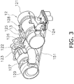
- FIG. 3 is a perspective view of the exhaust gas post-processing device 12 as seen from the left rear. As illustrated in FIG. 3 , the exhaust gas post-processing device 12 includes, in order of the flow of exhaust gas, a diesel particulate filtering device 121, a connecting pipe 122, and a selective catalyst reduction device 123. A urea water injection device 13 is attached to the connecting pipe 122.
- the diesel particulate filtering device 121 is connected to the engine 11 through a pipe 124.
- the diesel particulate filtering device 121 is a device for processing exhaust from the engine 11.
- the diesel particulate filtering device 121 is a device that collects, in a filter, particulate matter such as soot in the exhaust gas emitted from the engine 11.
- the diesel particulate filtering device 121 burns the collected particulate matter with a heater provided with the filter.
- the diesel particulate filtering device 121 is supported by a supporting member 151 attached to the vehicle frame 150.
- the connecting pipe 122 is a pipe for connecting the diesel particulate filtering device 121 and the selective catalyst reduction device 123.
- the entire connecting pipe 122 is formed in an S-shape and includes a first bend part 125, a linear part 126, and a second bend part 127.
- the first bend part 125 is connected to an exhaust gas lead-out port 128 of the diesel particulate filtering device 121.
- the second bend part 127 is connected to an exhaust gas inlet port 129 of the selective catalyst reduction device 123.
- the linear part 126 extends between the first bend part 125 and the second bend part 127.
- the urea water injection device 13 is attached to the first bend part 125.
- the urea water injection device 13 injects a urea water aqueous solution into the connecting pipe 122.
- the urea water aqueous solution is sucked up from a urea water aqueous solution tank (not shown) by a pump (not shown) and is supplied to the urea water injection device 13 via a connecting pipe (not shown).
- the urea water aqueous solution injected into the connecting pipe 122 undergoes hydrolysis due to the heat from the exhaust gas and becomes ammonia.
- the ammonia is fed with the exhaust gas through the connecting pipe 122 to the selective catalyst reduction device 123.
- the abovementioned ammonia is used as a reducing agent to purify by reduction the nitrogen oxides in the exhaust gas in the selective catalyst reduction device 123.
- the selective catalyst reduction device 123 is supported by the supporting member 151 in the same way as the diesel particulate filtering device 121.
- the diesel particulate filtering device 121 and the selective catalyst reduction device 123 are disposed parallel to each other. Specifically, the diesel particulate filtering device 121 and the selective catalyst reduction device 123 both have substantially tubular shapes. The center axes of the diesel particulate filtering device 121 and the selective catalyst reduction device 123 are both substantially disposed so as to extend substantially parallel to each other in the vehicle width direction.
- the linear part 126 in the connecting pipe 122 also has a substantially tubular shape and the center axis thereof extends in the vehicle width direction. Specifically, the center axis of the linear part 126 of the connecting pipe 122 is disposed substantially parallel to the center axes of the diesel particulate filtering device 121 and the selective catalyst reduction device 123.
- the cooling compartment 3 is disposed to the rear of the engine compartment 2 as illustrated in FIG. 2 .
- the engine compartment 2 and the cooling compartment 3 are partitioned by a partition wall 6.
- the cooling compartment 3 is defined by the vehicle body cover 8 in the same way as the engine compartment 2.
- the upper surface of the cooling compartment 3 is defined by the top plate 81 and the sides of the cooling compartment 3 are defined by the first and second side plates 82 and 83.
- a front part of the top plate 81 defines the upper surface of the engine compartment 2, and a rear part of the top plate 81 defines the upper surface of the cooling compartment 3.
- the front parts of the first and second side plates 82 and 83 define the side surfaces of the engine compartment 2, and the rear parts of the first and second side plates 82 and 83 define the side surfaces of the cooling compartment 3.
- a radiator 4 and a cooling fan 5 are contained inside the cooling compartment 3.
- the radiator 4 cools cooling liquid for the engine 11.
- the cooling fan 5 rotates so as to exhaust air from inside the cooling compartment 3 to the outside of the cooling compartment 3.
- the cooling fan 5 rotates so as to exhaust air from inside the cooling compartment 3 to the outside of the cooling compartment 3 via a grille 31.
- the cooling fan 5 generates an air flow toward the rear.
- the cooling fan 5 is disposed to the rear of the radiator 4.
- the grille 31 defines the rear surface of the cooling compartment 3.
- FIG. 4 is a perspective view of the under side of the top plate 81 and FIG. 5 is a side view of the top plate 81.
- the top plate 81 is a member that can be opened. That is, the top plate 81 is a member that can be removed.
- the top plate 81 is supported in a removable manner on the vehicle frame 150. While not limited in particular, the top plate 81 is attached to the vehicle frame 150 by a fastening member such as a bolt.
- a front part of the top plate 81 defines the upper surface of the engine compartment 2, and a rear part of the top plate 81 defines the upper surface of the cooling compartment 3.
- the front part of the top plate 81 is formed to protrude upward.
- the rear part of the top plate 81 has a first outdoor air intake port 84 formed therein.
- the first outdoor air intake port 84 is an opening part for sucking in outdoor air into the cooling compartment 3.
- the cooling compartment 3 communicates with the outside through the first outdoor air intake port 84.
- the first outdoor air intake port 84 is positioned in front of the radiator 4 and the cooling fan 5 in the front-back direction while the top plate 81 is attached to the vehicle frame 150.
- the first outdoor air intake port 84 is positioned on the upper surface of the cooling compartment 3 and allows communication between the cooling compartment 3 and the outside while the top plate 81 is attached to the vehicle frame 150.
- the front end of the first outdoor air intake port 84 is positioned to the rear of the partition wall 6 in the front-back direction, and the rear end of the first outdoor air intake port 84 is positioned in front of the radiator 4 in the front-back direction.
- the first outdoor air intake port 84 is configured of a plurality of through-holes.
- the first outdoor air intake port 84 has a substantially rectangular shape as seen in a plan view.
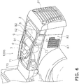
- FIG. 6 is a perspective view of a rear vehicle part when the top plate 81 is removed.
- a second outdoor air intake port 87 is formed in the first side plate 82 that is a portion of the vehicle body cover 8.
- the second outdoor air intake port 87 is an opening part for sucking in outdoor air into the cooling compartment 3.
- the cooling compartment 3 communicates with the outside through the second outdoor air intake port 87.
- the second outdoor air intake port 87 is positioned in front of the radiator 4 and the cooling fan 5 in the front-back direction. Specifically, at least a portion of the second outdoor air intake port 87 is positioned in front of the radiator 4.
- the second outdoor air intake port 87 is positioned on the left side surface (example of the first side surface) of the cooling compartment 3 and allows communication between the cooling compartment 3 and the outside.
- the second outdoor air intake port 87 is configured of a plurality of through-holes.
- a third outdoor air intake port 89 (see FIG. 2 ) is formed in the second side plate 83 that defines the right side surface (example of the second side surface) of the cooling compartment 3. A detailed explanation of the third outdoor air intake port 89 is omitted since the configuration thereof is the same as that of the second outdoor air intake port 87.
- the top plate 81 has the top plate body part 85 and a plurality of leg parts 86.
- the top plate body part 85 is a portion that defines the upper surfaces of the engine compartment 2 and the cooling compartment 3.
- the leg parts 86 are portions that extend downward from the side edge parts of the top plate body part 85.
- a lower end of a belowmentioned first duct body part 7 is positioned higher than a lower end of the leg parts 86.
- a lower end of a belowmentioned second duct body part 9 is positioned higher than the lower end of the leg parts 86.
- the leg parts 86 touch the ground and the second duct body part 9 does not touch the ground.
- the wheel loader 100 is further provided with the first and second duct body parts 7 and 9.
- the first and second duct body parts 7 and 9 extend so as to cross between the engine compartment 2 and the cooling compartment 3. Specifically, the first and second duct body parts 7 and 9 extend to pass through the partition wall 6.
- the first duct body part 7 has first and second end parts 71 and 72.
- the first end part 71 of the first duct body part 7 is positioned inside the engine compartment 2.
- the second end part 72 of the first duct body part 7 is positioned inside the cooling compartment 3.
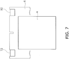
- the second end part 72 is positioned in front of the radiator 4 and the cooling fan 5 in the front-back direction. Specifically, the second end part 72 is positioned near the partition wall 6.
- the second end part 72 is disposed in a position that does not face the radiator 4 in a back view. Specifically, the second end part 72 is positioned in an upper end part and a left side end part (example of the first side end part) inside the cooling compartment 3. That is, the second end part 72 is positioned near the first outdoor air intake port 84 and the second outdoor air intake port 87.
- FIG. 7 is a schematic view depicting a positional relationship between the radiator 4 and the duct body parts in the back view.
- the first duct body part 7 is attached to the top plate 81.
- the first duct body part 7 is attached to the top plate 81 by a fixing means such as a mounting bracket or by welding and the like.
- the first duct body part 7 can be integrally removed with the top plate 81 by removing the top plate 81 from the vehicle frame 150.
- the rear end part of the first duct body part 7 is supported by a beam member 88.
- the beam member 88 is fixed to the top plate body part 85.
- the beam member 88 extends in the vehicle width direction, and more specifically, extends from the left side end part (example of the first side end part) to the right side end part (example of the second side end part) of the top plate body part 85.
- the beam member 88 has first and second through-holes 881 and 882 that extend in the front-back direction.
- the first through-hole 881 is formed in the left side end part and the second through-hole 882 is formed in the right side end part.
- the first duct body part 7 is supported on the beam member 88 by passing through the first through-hole 881. A portion of the left side surface of the first duct body part 7 is welded to the inside surface of the top plate 81.
- the first duct body part 7 is disposed in the left side end part (example of the first side end part) inside the engine compartment 2.
- the cross-section of the first duct body part 7 vertical to the longitudinal direction has a rectangular shape.
- the first duct body part 7 extends substantially in the front-back direction.
- the first duct body part 7 approaches the middle in the vehicle width direction as the first duct body part 7 extends to the front.
- FIG. 8 is a perspective view of the inside of the engine compartment 2 as seen from the rear. As illustrated in FIG. 8 , a first intake part 74 and a second intake part 75 are connected to the first end part 71 of the first duct body part 7.
- the first intake part 74 extends from the first end part 71 of the first duct body part 7 toward a first member to be cooled 21. Specifically, the first intake part 74 is disposed so as to suck in the air around the first member to be cooled 21.
- the first member to be cooled 21 is disposed inside the engine compartment 2.
- the first member to be cooled 21 is a NOx sensor and measures the NOx concentration inside the selective catalyst reduction device 123.
- the first intake part 74 is attached in a removable manner to the first end part 71 of the first duct body part 7. Specifically, the first intake part 74 is attached to the first end part 71 of the first duct body part 7 via a flexible pipe 76. The pipe 76 can be removed from the first intake part 74 by removing a band member 77. The first intake part 74 is fixed to the supporting member 151 inside of the engine compartment 2 with a mounting bracket and the like.
- the first intake part 74 is substantially shaped as an L. Specifically, the first intake part 74 has a first part 741 that extends downward and a second part 742 that extends in the vehicle width direction. The first part 741 extends downward from the first end part 71 of the first duct body part 7. The second part 742 extends from the lower end part of the first part 741 to the right side (example of the second side). Air around the first member to be cooled 21 is sucked in from the distal end part of the second part 742.
- the second intake part 75 extends from the first end part 71 of the first duct body part 7 toward a second member to be cooled 22. Specifically, the second intake part 75 is disposed so as to suck in the air around the second member to be cooled 22. The second intake part 75 extends from the first end part 71 of the first duct body part 7 to the right side (example of the second side) . The second intake part 75 is fixed to the top plate 81 with a mounting bracket and the like. As a result, the second intake part 75 is removed integrally with the top plate 81.
- the second member to be cooled 22 is disposed inside the engine compartment 2.
- the second member to be cooled 22 is a temperature sensor and measures the temperature inside the selective catalyst reduction device 123.
- the flow passage area in the first duct body part 7 is larger than the flow passage area of the first intake part 74 or larger than the flow passage area of the second intake part 75.
- the second duct body part 9 has third and fourth end parts 91 and 92.
- the third end part 91 is positioned inside the engine compartment 2.
- the fourth end part 92 is positioned inside the cooling compartment 3.
- the fourth end part 92 is positioned in front of the radiator 4 and the cooling fan 5 in the front-back direction.
- the fourth end part 92 is disposed in a position that does not face the radiator 4 in the back view. Specifically, the fourth end part 92 is positioned in an upper end part and a right side end part (example of the second side end part) inside the cooling compartment 3. That is, the fourth end part 92 is positioned near the first outdoor air intake port 84 and the third outdoor air intake port 89.
- the second duct body part 9 is attached to the top plate 81.
- the second duct body part 9 is attached to the top plate 81 by a fixing means such as a mounting bracket or by welding and the like.
- the second duct body part 9 can be integrally removed with the top plate 81 by removing the top plate 81 from the vehicle frame 150.
- the rear end part of the second duct body part 9 is supported by the beam member 88.
- the second duct body part 9 is supported on the beam member 88 by passing through the second through-hole 882.
- a portion of the right side surface of the second duct body part 9 is welded to the inside surface of the top plate 81.
- the second duct body part 9 is disposed in the right side end part (example of the second side end part) inside the engine compartment 2.
- the cross-section of the second duct body part 9 vertical to the longitudinal direction has a rectangular shape.
- the second duct body part 9 extends substantially in the front-back direction.
- the third end part 91 of the second duct body part 9 opens toward the urea water injection device 13.
- the second duct body part 9 mainly extends along the top plate 81 and a portion at the third end part 91 side is configured to face frontward and downward.
- the partition wall 6 has notch parts 61 and 62 for allowing the duct body parts 7 and 9 to pass therethrough.
- the first and second notch parts 61 and 62 are formed in the upper end part of the partition wall 6.
- the first notch part 61 is formed in the upper end part and the left side end part (example of the first side end part) of the partition wall 6.
- the first duct body part 7 extends between the engine compartment 2 and the cooling compartment 3 via the first notch part 61.
- the second notch part 62 is formed in the upper end part and the right side end part (example of the second side end part) of the partition wall 6.
- the second duct body part 9 extends between the engine compartment 2 and the cooling compartment 3 via the second notch part 62.
- the wheel loader 100 has the following characteristics.
- the second end part 72 of the first duct body part 7 is positioned inside the cooling compartment 3.
- the cooling compartment 3 is a space with negative pressure when the cooling fan 5 is operating.
- the first duct body part 7 sucks in air from the first end part 71 and exhausts the air from the second end part 72. Consequently, hot air inside the engine compartment 2 is exhausted to the cooling compartment 3 and an excessive rise in temperature inside the engine compartment can be suppressed. Since a negative pressure is developed inside the engine compartment 2 due to the hot air inside the engine compartment 2 being exhausted to the cooling compartment 3, outdoor air flows into the engine compartment 2 and the inside of the engine compartment 2 can be cooled.
- the front part of the top plate 81 has an intake port 811 formed therein for introducing outdoor air into the engine compartment 2.
- the second end part 72, the first outdoor air intake port 84, the second outdoor air intake port 87, and the third outdoor air intake port 89 are positioned in front of the radiator 4 and the cooling fan 5 in the front-back direction.
- hot air exhausted from the second end part 72 into the cooling compartment 3 becomes mixed with outdoor air sucked into the cooling compartment 3 from the first, second, and third outdoor air intake ports 84, 87, and 89, and the mixed hot air and outdoor air flows toward the radiator 4. That is, a direct flow of only the hot air exhausted from the second end part 72 to the radiator 4 is suppressed.
- a reduction in the cooling efficiency of the radiator 4 due to the hot air from the second end part 72 can be suppressed.
- the second end part 72 and the fourth end part 92 of the above embodiment are not limited to being positioned in front of the radiator 4 and the cooling fan 5.
- the second end part 72 and the fourth end part 92 may be positioned to the rear of the radiator 4 and in front of the cooling fan 5.
- the second and fourth end parts 72 and 92 may be positioned between the radiator 4 and the cooling fan 5 in the front-back direction.
- the entire first outdoor air intake port 84 of the above embodiment is not limited to being positioned in front of the radiator 4 and the cooling fan 5.
- the rear end part of the first outdoor air intake port 84 may be positioned to the rear of the radiator 4.
- first and second duct body parts 7 and 9 are provided in the above embodiment, the number thereof is not limited. Specifically, only one of the first and second duct body parts 7 and 9 may be provided.
- the number of the outdoor air intake ports is not limited to three.
- only one of the first, second, and third outdoor air intake ports 84 and 87 may be formed.
- top plate 81 is configured to be removable in the above embodiment, the top plate 81 is not limited as such.
- the top plate 81 may be attached to the vehicle frame 150 in a manner that allows swinging.
- the top plate 81 may be attached to the vehicle frame 150 via a hinge.
- a diesel oxidation catalyst may also be disposed in place of the diesel particulate filtering device 121 in the above embodiment.
- the present invention may be applicable to another work vehicle such as a motor grader.
Landscapes
- Engineering & Computer Science (AREA)
- Chemical & Material Sciences (AREA)
- Combustion & Propulsion (AREA)
- Mechanical Engineering (AREA)
- General Engineering & Computer Science (AREA)
- Transportation (AREA)
- Mining & Mineral Resources (AREA)
- Civil Engineering (AREA)
- Structural Engineering (AREA)
- Component Parts Of Construction Machinery (AREA)
- Cooling, Air Intake And Gas Exhaust, And Fuel Tank Arrangements In Propulsion Units (AREA)
Claims (8)
- Véhicule de chantier comprenant :un compartiment moteur (2) ;un compartiment de refroidissement (3) ;une paroi de cloisonnement (6) qui cloisonne le compartiment moteur (2) vis-à-vis du compartiment de refroidissement (3) ;un ventilateur de refroidissement (5) contenu dans le compartiment de refroidissement (3) et évacuant l'air hors du compartiment de refroidissement (3);une plaque supérieure (81) configurée pour pouvoir être ouverte et définissant une surface supérieure du compartiment moteur (2) ; etune première partie formant corps de conduit (7) attachée à la plaque supérieure (81) et ayant une première partie terminale (71) et une seconde partie terminale (72), la première partie terminale (71) étant positionnée à l'intérieur du compartiment moteur (2), la seconde partie terminale (72) étant positionnée à l'intérieur du compartiment de refroidissement (3),caractérisé en ce que la première partie formant corps de conduit (7) est configuré pour aspirer de l'air depuis la première partie terminale (71) et pour évacuer l'air depuis la seconde partie terminale (72).
- Véhicule de chantier selon la revendication 1, comprenant en outre :un premier élément à refroidir (21) disposé à l'intérieur du compartiment moteur (2) ; etune première partie d'admission (74) qui s'étend depuis la première partie terminale (71) de la première partie formant corps de conduit (7) en direction du premier élément à refroidir (21).
- Véhicule de chantier selon la revendication 2, dans lequel
la première partie d'admission (74) est attachée de façon amovible à la première partie terminale (71) de la première partie formant corps de conduit (7). - Véhicule de chantier selon l'une quelconque des revendications 2 ou 3, comprenant en outre :un second élément à refroidir (22) disposé à l'intérieur du compartiment moteur (2) ; etune seconde partie d'admission (75) qui s'étend depuis la première partie terminale (71) de la première partie formant corps de conduit (7) vers le second élément à refroidir (22).
- Véhicule de chantier selon la revendication 4, dans lequel
une aire de passage d'écoulement dans la première partie formant corps de conduit (7) est plus grande qu'une aire de passage d'écoulement de la première partie d'admission (74), et l'aire de passage d'écoulement dans la première partie formant corps de conduit (7) est plus grande qu'une aire de passage d'écoulement de la seconde partie d'admission (75). - Véhicule de chantier selon l'une quelconque des revendications 1 à 5, dans lequel :la plaque supérieure (81) a une partie formant corps de plaque supérieure (85) et une partie formant pied (86), la partie formant corps de plaque supérieure (85) définissant une surface supérieure du compartiment moteur (2), la partie formant pied (86) s'étendant vers le bas depuis la partie formant corps de plaque supérieure (85) ; etune extrémité inférieure de la première partie formant corps de conduit (7) est positionnée plus haut qu'une extrémité inférieure de la partie formant pied (86).
- Véhicule de chantier selon l'une quelconque des revendications 1 à 6, dans lequel :la paroi de cloisonnement (6) comporte une partie en encoche (62) dans une partie d'extrémité supérieure ; etla première partie formant corps de conduit (7) s'étend entre le compartiment moteur (2) et le compartiment de refroidissement (3) via la partie en encoche (62).
- Véhicule de chantier selon l'une quelconque des revendications 1 à 7, comprenant en outre :une seconde partie formant corps de conduit (9) attachée à la plaque supérieure (81) et ayant une troisième partie d'extrémité (91) et une quatrième partie d'extrémité (92), la troisième partie d'extrémité (91) étant positionnée à l'intérieur du compartiment moteur (2), la quatrième partie d'extrémité (92) étant positionnée à l'intérieur du compartiment de refroidissement (3).
Applications Claiming Priority (1)
| Application Number | Priority Date | Filing Date | Title |
|---|---|---|---|
| PCT/JP2014/059420 WO2014181612A1 (fr) | 2014-03-31 | 2014-03-31 | Véhicule utilitaire |
Publications (3)
| Publication Number | Publication Date |
|---|---|
| EP3009759A1 EP3009759A1 (fr) | 2016-04-20 |
| EP3009759A4 EP3009759A4 (fr) | 2016-11-02 |
| EP3009759B1 true EP3009759B1 (fr) | 2018-03-21 |
Family
ID=51469664
Family Applications (1)
| Application Number | Title | Priority Date | Filing Date |
|---|---|---|---|
| EP14720039.8A Not-in-force EP3009759B1 (fr) | 2014-03-31 | 2014-03-31 | Véhicule utilitaire |
Country Status (5)
| Country | Link |
|---|---|
| US (1) | US9033081B1 (fr) |
| EP (1) | EP3009759B1 (fr) |
| JP (1) | JP5629845B1 (fr) |
| CN (1) | CN104039576B (fr) |
| WO (1) | WO2014181612A1 (fr) |
Families Citing this family (10)
| Publication number | Priority date | Publication date | Assignee | Title |
|---|---|---|---|---|
| WO2014192405A1 (fr) * | 2014-03-31 | 2014-12-04 | 株式会社小松製作所 | Véhicule de travail |
| JP6297905B2 (ja) * | 2014-04-22 | 2018-03-20 | 日立建機株式会社 | 建設機械 |
| JP6275552B2 (ja) * | 2014-05-29 | 2018-02-07 | ヤンマー株式会社 | 作業車両 |
| CN104903135B (zh) * | 2014-08-19 | 2017-06-23 | 株式会社小松制作所 | 作业车辆 |
| EP2947210B1 (fr) * | 2015-03-10 | 2018-07-11 | Komatsu Ltd. | Véhicule industriel |
| EP2955280B1 (fr) * | 2015-03-10 | 2017-10-25 | Komatsu Ltd. | Véhicule industriel |
| CA3217821C (fr) * | 2016-04-28 | 2025-10-14 | Bombardier Recreational Products Inc. | Systeme d'admission d'air pour vehicule tout-terrain |
| WO2017043300A1 (fr) * | 2016-08-22 | 2017-03-16 | 株式会社小松製作所 | Véhicule de travail |
| CN106638755A (zh) * | 2017-01-09 | 2017-05-10 | 重庆永重重工有限公司 | 装载机铲斗 |
| EP3670223B1 (fr) * | 2018-12-21 | 2022-06-29 | Valeo Autosystemy SP. Z.O.O. | Système de chauffage, de ventilation et de conditionnement d'air |
Family Cites Families (30)
| Publication number | Priority date | Publication date | Assignee | Title |
|---|---|---|---|---|
| JPS6079155A (ja) * | 1983-09-14 | 1985-05-04 | Nissan Shatai Co Ltd | 自動車用燃料冷却装置 |
| JP2510543Y2 (ja) * | 1991-06-21 | 1996-09-11 | 本田技研工業株式会社 | エンジンル―ム内温度制御装置 |
| JPH05521A (ja) | 1991-06-25 | 1993-01-08 | Oki Electric Ind Co Ltd | ワイヤ印字ヘツド及びその製造方法 |
| US5199522A (en) * | 1992-05-27 | 1993-04-06 | Ford New Holland, Inc. | Air inlet for vehicle engine |
| DE69603210T2 (de) * | 1995-02-17 | 2000-01-20 | Kubota Corp., Osaka | Schaufelbagger mit einer Motorhaube an welcher der Fahrersitz befestigt ist |
| US6230832B1 (en) * | 1996-09-04 | 2001-05-15 | Freightliner Llc | Truck underhood air flow management system |
| US6032620A (en) * | 1997-10-31 | 2000-03-07 | Kabushiki Kaisha Kobe Seiko Sho | Air intake structure in a construction machine |
| JP4450298B2 (ja) * | 2000-01-12 | 2010-04-14 | 株式会社小松製作所 | 建設機械のエンジン冷却風路 |
| JP2001200771A (ja) * | 2000-01-18 | 2001-07-27 | Ishikawajima Constr Mach Co | 消音ダクト |
| JP2002021565A (ja) * | 2000-07-11 | 2002-01-23 | Komatsu Ltd | 建設車両のエンジン囲い |
| WO2002044479A1 (fr) * | 2000-12-01 | 2002-06-06 | Hitachi Construction Machinery Co., Ltd | Machines de chantier |
| US6823955B2 (en) * | 2001-06-27 | 2004-11-30 | Deere & Company | 360 degree air intake screen |
| US7575081B2 (en) * | 2004-03-29 | 2009-08-18 | Kubota Corporation | Work vehicle |
| JP2007283801A (ja) * | 2006-04-12 | 2007-11-01 | Hitachi Constr Mach Co Ltd | 建設機械 |
| WO2008055216A2 (fr) * | 2006-10-31 | 2008-05-08 | Enviro-Cool, Inc. | Système de gestion de l'air pour camions poids lourds avec régulation thermique sous le capot |
| US20080142285A1 (en) * | 2006-12-18 | 2008-06-19 | Caterpillar Inc. | Airflow redirector |
| US8215434B2 (en) * | 2007-06-26 | 2012-07-10 | Hitachi Construction Machinery Co., Ltd. | Construction machine |
| US8403089B2 (en) * | 2008-12-23 | 2013-03-26 | Deere & Company | Use of fan shroud to ventilate engine compartment |
| JP5184387B2 (ja) * | 2009-01-09 | 2013-04-17 | ヤンマー株式会社 | ボンネット構造 |
| JP5172898B2 (ja) * | 2010-06-15 | 2013-03-27 | 日立建機株式会社 | 電動式建設機械 |
| US8919469B2 (en) * | 2010-08-26 | 2014-12-30 | Caterpillar Inc. | Ventilation system for engine and aftertreatment compartments and components |
| JP5192540B2 (ja) | 2010-12-24 | 2013-05-08 | 株式会社小松製作所 | 作業車両 |
| US8939733B2 (en) * | 2011-06-22 | 2015-01-27 | Caterpillar Inc. | Hydraulic fan assembly for an engine ventilation system |
| JP5948966B2 (ja) * | 2012-03-01 | 2016-07-06 | コベルコ建機株式会社 | 建設機械の吸気構造 |
| JP5130410B1 (ja) | 2012-07-26 | 2013-01-30 | 株式会社小松製作所 | 作業車両 |
| JP5684768B2 (ja) * | 2012-09-27 | 2015-03-18 | 株式会社クボタ | 作業車 |
| JP5591303B2 (ja) * | 2012-10-25 | 2014-09-17 | 株式会社小松製作所 | エンジン室の換気構造 |
| EP2733342B1 (fr) * | 2012-11-15 | 2015-08-19 | CNH Industrial Italia S.p.A. | Agencement de filtre à air pour véhicule de travail |
| EP2792795B1 (fr) * | 2013-02-22 | 2015-04-08 | Komatsu Ltd. | Chargeur à roues |
| JP5733335B2 (ja) * | 2013-04-19 | 2015-06-10 | コベルコ建機株式会社 | 建設機械の排気構造 |
-
2014
- 2014-03-31 EP EP14720039.8A patent/EP3009759B1/fr not_active Not-in-force
- 2014-03-31 WO PCT/JP2014/059420 patent/WO2014181612A1/fr not_active Ceased
- 2014-03-31 JP JP2014534289A patent/JP5629845B1/ja active Active
- 2014-03-31 CN CN201480000293.1A patent/CN104039576B/zh not_active Expired - Fee Related
- 2014-03-31 US US14/356,649 patent/US9033081B1/en active Active
Non-Patent Citations (1)
| Title |
|---|
| None * |
Also Published As
| Publication number | Publication date |
|---|---|
| EP3009759A1 (fr) | 2016-04-20 |
| EP3009759A4 (fr) | 2016-11-02 |
| JPWO2014181612A1 (ja) | 2017-02-23 |
| JP5629845B1 (ja) | 2014-11-26 |
| CN104039576A (zh) | 2014-09-10 |
| WO2014181612A1 (fr) | 2014-11-13 |
| US9033081B1 (en) | 2015-05-19 |
| CN104039576B (zh) | 2016-08-31 |
Similar Documents
| Publication | Publication Date | Title |
|---|---|---|
| EP3009759B1 (fr) | Véhicule utilitaire | |
| EP2842783B1 (fr) | Véhicule de travail | |
| US9309643B2 (en) | Work vehicle | |
| EP2891570B1 (fr) | Engin de travaux avec unité de refroidissement du compartiment moteur | |
| CN103797195B (zh) | 作业车辆 | |
| JP5635694B1 (ja) | 作業車両、及びホイールローダ | |
| JPWO2014155507A1 (ja) | 作業車両、及びホイールローダ | |
| CN104220288B (zh) | 作业车辆 | |
| US9528244B2 (en) | Work vehicle | |
| JP6046678B2 (ja) | 作業車両 |
Legal Events
| Date | Code | Title | Description |
|---|---|---|---|
| PUAI | Public reference made under article 153(3) epc to a published international application that has entered the european phase |
Free format text: ORIGINAL CODE: 0009012 |
|
| 17P | Request for examination filed |
Effective date: 20140508 |
|
| AK | Designated contracting states |
Kind code of ref document: A1 Designated state(s): AL AT BE BG CH CY CZ DE DK EE ES FI FR GB GR HR HU IE IS IT LI LT LU LV MC MK MT NL NO PL PT RO RS SE SI SK SM TR |
|
| AX | Request for extension of the european patent |
Extension state: BA ME |
|
| A4 | Supplementary search report drawn up and despatched |
Effective date: 20161005 |
|
| RIC1 | Information provided on ipc code assigned before grant |
Ipc: B60K 11/04 20060101ALI20160928BHEP Ipc: F01N 13/00 20100101ALN20160928BHEP Ipc: F01N 3/20 20060101ALN20160928BHEP Ipc: F01P 1/00 20060101ALI20160928BHEP Ipc: F01P 1/06 20060101ALI20160928BHEP Ipc: B60K 11/02 20060101ALI20160928BHEP Ipc: B60K 11/06 20060101ALI20160928BHEP Ipc: F01N 13/18 20100101ALN20160928BHEP Ipc: E02F 9/08 20060101ALI20160928BHEP Ipc: F24F 11/02 20060101AFI20160928BHEP Ipc: B60K 11/08 20060101ALI20160928BHEP |
|
| 17Q | First examination report despatched |
Effective date: 20170503 |
|
| DAX | Request for extension of the european patent (deleted) | ||
| GRAP | Despatch of communication of intention to grant a patent |
Free format text: ORIGINAL CODE: EPIDOSNIGR1 |
|
| RIC1 | Information provided on ipc code assigned before grant |
Ipc: F01P 1/00 20060101ALI20170808BHEP Ipc: F01N 13/18 20100101ALN20170808BHEP Ipc: B60K 11/06 20060101ALI20170808BHEP Ipc: B60K 11/02 20060101ALI20170808BHEP Ipc: B60K 11/08 20060101ALI20170808BHEP Ipc: E02F 9/08 20060101ALI20170808BHEP Ipc: B60K 11/04 20060101ALI20170808BHEP Ipc: F24F 11/02 20060101AFI20170808BHEP Ipc: F01N 3/20 20060101ALN20170808BHEP Ipc: F01P 1/06 20060101ALI20170808BHEP Ipc: F01N 13/00 20100101ALN20170808BHEP |
|
| INTG | Intention to grant announced |
Effective date: 20170825 |
|
| GRAJ | Information related to disapproval of communication of intention to grant by the applicant or resumption of examination proceedings by the epo deleted |
Free format text: ORIGINAL CODE: EPIDOSDIGR1 |
|
| GRAP | Despatch of communication of intention to grant a patent |
Free format text: ORIGINAL CODE: EPIDOSNIGR1 |
|
| INTC | Intention to grant announced (deleted) | ||
| RIC1 | Information provided on ipc code assigned before grant |
Ipc: F24F 11/02 20060101AFI20171017BHEP Ipc: F01N 13/00 20100101ALN20171017BHEP Ipc: F01N 3/20 20060101ALN20171017BHEP Ipc: F01P 1/00 20060101ALI20171017BHEP Ipc: B60K 11/06 20060101ALI20171017BHEP Ipc: B60K 11/04 20060101ALI20171017BHEP Ipc: F01P 1/06 20060101ALI20171017BHEP Ipc: E02F 9/08 20060101ALI20171017BHEP Ipc: B60K 11/08 20060101ALI20171017BHEP Ipc: B60K 11/02 20060101ALI20171017BHEP Ipc: F01N 13/18 20100101ALN20171017BHEP |
|
| INTG | Intention to grant announced |
Effective date: 20171113 |
|
| GRAS | Grant fee paid |
Free format text: ORIGINAL CODE: EPIDOSNIGR3 |
|
| GRAA | (expected) grant |
Free format text: ORIGINAL CODE: 0009210 |
|
| AK | Designated contracting states |
Kind code of ref document: B1 Designated state(s): AL AT BE BG CH CY CZ DE DK EE ES FI FR GB GR HR HU IE IS IT LI LT LU LV MC MK MT NL NO PL PT RO RS SE SI SK SM TR |
|
| REG | Reference to a national code |
Ref country code: GB Ref legal event code: FG4D |
|
| REG | Reference to a national code |
Ref country code: CH Ref legal event code: EP |
|
| REG | Reference to a national code |
Ref country code: AT Ref legal event code: REF Ref document number: 981539 Country of ref document: AT Kind code of ref document: T Effective date: 20180415 |
|
| REG | Reference to a national code |
Ref country code: IE Ref legal event code: FG4D |
|
| REG | Reference to a national code |
Ref country code: DE Ref legal event code: R096 Ref document number: 602014022596 Country of ref document: DE |
|
| REG | Reference to a national code |
Ref country code: SE Ref legal event code: TRGR |
|
| REG | Reference to a national code |
Ref country code: NL Ref legal event code: MP Effective date: 20180321 |
|
| PG25 | Lapsed in a contracting state [announced via postgrant information from national office to epo] |
Ref country code: HR Free format text: LAPSE BECAUSE OF FAILURE TO SUBMIT A TRANSLATION OF THE DESCRIPTION OR TO PAY THE FEE WITHIN THE PRESCRIBED TIME-LIMIT Effective date: 20180321 Ref country code: NO Free format text: LAPSE BECAUSE OF FAILURE TO SUBMIT A TRANSLATION OF THE DESCRIPTION OR TO PAY THE FEE WITHIN THE PRESCRIBED TIME-LIMIT Effective date: 20180621 Ref country code: CY Free format text: LAPSE BECAUSE OF FAILURE TO SUBMIT A TRANSLATION OF THE DESCRIPTION OR TO PAY THE FEE WITHIN THE PRESCRIBED TIME-LIMIT Effective date: 20180321 Ref country code: LT Free format text: LAPSE BECAUSE OF FAILURE TO SUBMIT A TRANSLATION OF THE DESCRIPTION OR TO PAY THE FEE WITHIN THE PRESCRIBED TIME-LIMIT Effective date: 20180321 Ref country code: FI Free format text: LAPSE BECAUSE OF FAILURE TO SUBMIT A TRANSLATION OF THE DESCRIPTION OR TO PAY THE FEE WITHIN THE PRESCRIBED TIME-LIMIT Effective date: 20180321 |
|
| REG | Reference to a national code |
Ref country code: LT Ref legal event code: MG4D |
|
| REG | Reference to a national code |
Ref country code: AT Ref legal event code: MK05 Ref document number: 981539 Country of ref document: AT Kind code of ref document: T Effective date: 20180321 |
|
| PG25 | Lapsed in a contracting state [announced via postgrant information from national office to epo] |
Ref country code: GR Free format text: LAPSE BECAUSE OF FAILURE TO SUBMIT A TRANSLATION OF THE DESCRIPTION OR TO PAY THE FEE WITHIN THE PRESCRIBED TIME-LIMIT Effective date: 20180622 Ref country code: LV Free format text: LAPSE BECAUSE OF FAILURE TO SUBMIT A TRANSLATION OF THE DESCRIPTION OR TO PAY THE FEE WITHIN THE PRESCRIBED TIME-LIMIT Effective date: 20180321 Ref country code: BG Free format text: LAPSE BECAUSE OF FAILURE TO SUBMIT A TRANSLATION OF THE DESCRIPTION OR TO PAY THE FEE WITHIN THE PRESCRIBED TIME-LIMIT Effective date: 20180621 Ref country code: RS Free format text: LAPSE BECAUSE OF FAILURE TO SUBMIT A TRANSLATION OF THE DESCRIPTION OR TO PAY THE FEE WITHIN THE PRESCRIBED TIME-LIMIT Effective date: 20180321 |
|
| PG25 | Lapsed in a contracting state [announced via postgrant information from national office to epo] |
Ref country code: NL Free format text: LAPSE BECAUSE OF FAILURE TO SUBMIT A TRANSLATION OF THE DESCRIPTION OR TO PAY THE FEE WITHIN THE PRESCRIBED TIME-LIMIT Effective date: 20180321 Ref country code: ES Free format text: LAPSE BECAUSE OF FAILURE TO SUBMIT A TRANSLATION OF THE DESCRIPTION OR TO PAY THE FEE WITHIN THE PRESCRIBED TIME-LIMIT Effective date: 20180321 Ref country code: PL Free format text: LAPSE BECAUSE OF FAILURE TO SUBMIT A TRANSLATION OF THE DESCRIPTION OR TO PAY THE FEE WITHIN THE PRESCRIBED TIME-LIMIT Effective date: 20180321 Ref country code: AL Free format text: LAPSE BECAUSE OF FAILURE TO SUBMIT A TRANSLATION OF THE DESCRIPTION OR TO PAY THE FEE WITHIN THE PRESCRIBED TIME-LIMIT Effective date: 20180321 Ref country code: IT Free format text: LAPSE BECAUSE OF FAILURE TO SUBMIT A TRANSLATION OF THE DESCRIPTION OR TO PAY THE FEE WITHIN THE PRESCRIBED TIME-LIMIT Effective date: 20180321 Ref country code: RO Free format text: LAPSE BECAUSE OF FAILURE TO SUBMIT A TRANSLATION OF THE DESCRIPTION OR TO PAY THE FEE WITHIN THE PRESCRIBED TIME-LIMIT Effective date: 20180321 Ref country code: EE Free format text: LAPSE BECAUSE OF FAILURE TO SUBMIT A TRANSLATION OF THE DESCRIPTION OR TO PAY THE FEE WITHIN THE PRESCRIBED TIME-LIMIT Effective date: 20180321 |
|
| REG | Reference to a national code |
Ref country code: CH Ref legal event code: PL |
|
| PG25 | Lapsed in a contracting state [announced via postgrant information from national office to epo] |
Ref country code: CZ Free format text: LAPSE BECAUSE OF FAILURE TO SUBMIT A TRANSLATION OF THE DESCRIPTION OR TO PAY THE FEE WITHIN THE PRESCRIBED TIME-LIMIT Effective date: 20180321 Ref country code: SM Free format text: LAPSE BECAUSE OF FAILURE TO SUBMIT A TRANSLATION OF THE DESCRIPTION OR TO PAY THE FEE WITHIN THE PRESCRIBED TIME-LIMIT Effective date: 20180321 Ref country code: AT Free format text: LAPSE BECAUSE OF FAILURE TO SUBMIT A TRANSLATION OF THE DESCRIPTION OR TO PAY THE FEE WITHIN THE PRESCRIBED TIME-LIMIT Effective date: 20180321 Ref country code: SK Free format text: LAPSE BECAUSE OF FAILURE TO SUBMIT A TRANSLATION OF THE DESCRIPTION OR TO PAY THE FEE WITHIN THE PRESCRIBED TIME-LIMIT Effective date: 20180321 |
|
| REG | Reference to a national code |
Ref country code: BE Ref legal event code: MM Effective date: 20180331 |
|
| REG | Reference to a national code |
Ref country code: IE Ref legal event code: MM4A |
|
| PG25 | Lapsed in a contracting state [announced via postgrant information from national office to epo] |
Ref country code: LU Free format text: LAPSE BECAUSE OF NON-PAYMENT OF DUE FEES Effective date: 20180331 Ref country code: PT Free format text: LAPSE BECAUSE OF FAILURE TO SUBMIT A TRANSLATION OF THE DESCRIPTION OR TO PAY THE FEE WITHIN THE PRESCRIBED TIME-LIMIT Effective date: 20180723 |
|
| REG | Reference to a national code |
Ref country code: DE Ref legal event code: R097 Ref document number: 602014022596 Country of ref document: DE |
|
| RIC2 | Information provided on ipc code assigned after grant |
Ipc: F01N 3/20 20060101ALN20171017BHEP Ipc: F01P 1/06 20060101ALI20171017BHEP Ipc: F01N 13/00 20100101ALN20171017BHEP Ipc: B60K 11/04 20060101ALI20171017BHEP Ipc: E02F 9/08 20060101ALI20171017BHEP Ipc: F01P 1/00 20060101ALI20171017BHEP Ipc: B60K 11/08 20060101ALI20171017BHEP Ipc: B60K 11/02 20060101ALI20171017BHEP Ipc: F24F 11/02 20181130AFI20171017BHEP Ipc: F01N 13/18 20100101ALN20171017BHEP Ipc: B60K 11/06 20060101ALI20171017BHEP |
|
| PLBE | No opposition filed within time limit |
Free format text: ORIGINAL CODE: 0009261 |
|
| STAA | Information on the status of an ep patent application or granted ep patent |
Free format text: STATUS: NO OPPOSITION FILED WITHIN TIME LIMIT |
|
| PG25 | Lapsed in a contracting state [announced via postgrant information from national office to epo] |
Ref country code: MC Free format text: LAPSE BECAUSE OF FAILURE TO SUBMIT A TRANSLATION OF THE DESCRIPTION OR TO PAY THE FEE WITHIN THE PRESCRIBED TIME-LIMIT Effective date: 20180321 Ref country code: DK Free format text: LAPSE BECAUSE OF FAILURE TO SUBMIT A TRANSLATION OF THE DESCRIPTION OR TO PAY THE FEE WITHIN THE PRESCRIBED TIME-LIMIT Effective date: 20180321 Ref country code: IE Free format text: LAPSE BECAUSE OF NON-PAYMENT OF DUE FEES Effective date: 20180331 |
|
| RIC2 | Information provided on ipc code assigned after grant |
Ipc: B60K 11/02 20060101ALI20171017BHEP Ipc: F01P 1/06 20060101ALI20171017BHEP Ipc: F01N 13/18 20100101ALN20171017BHEP Ipc: F01N 13/00 20100101ALN20171017BHEP Ipc: B60K 11/08 20060101ALI20171017BHEP Ipc: E02F 9/08 20060101ALI20171017BHEP Ipc: F01N 3/20 20060101ALN20171017BHEP Ipc: F01P 1/00 20060101ALI20171017BHEP Ipc: B60K 11/04 20060101ALI20171017BHEP Ipc: F24F 11/02 20060101AFI20171017BHEP Ipc: B60K 11/06 20060101ALI20171017BHEP |
|
| 26N | No opposition filed |
Effective date: 20190102 |
|
| GBPC | Gb: european patent ceased through non-payment of renewal fee |
Effective date: 20180621 |
|
| PG25 | Lapsed in a contracting state [announced via postgrant information from national office to epo] |
Ref country code: BE Free format text: LAPSE BECAUSE OF NON-PAYMENT OF DUE FEES Effective date: 20180331 Ref country code: CH Free format text: LAPSE BECAUSE OF NON-PAYMENT OF DUE FEES Effective date: 20180331 Ref country code: LI Free format text: LAPSE BECAUSE OF NON-PAYMENT OF DUE FEES Effective date: 20180331 |
|
| PG25 | Lapsed in a contracting state [announced via postgrant information from national office to epo] |
Ref country code: GB Free format text: LAPSE BECAUSE OF NON-PAYMENT OF DUE FEES Effective date: 20180621 Ref country code: FR Free format text: LAPSE BECAUSE OF NON-PAYMENT OF DUE FEES Effective date: 20180521 |
|
| PG25 | Lapsed in a contracting state [announced via postgrant information from national office to epo] |
Ref country code: SI Free format text: LAPSE BECAUSE OF FAILURE TO SUBMIT A TRANSLATION OF THE DESCRIPTION OR TO PAY THE FEE WITHIN THE PRESCRIBED TIME-LIMIT Effective date: 20180321 |
|
| PG25 | Lapsed in a contracting state [announced via postgrant information from national office to epo] |
Ref country code: MT Free format text: LAPSE BECAUSE OF NON-PAYMENT OF DUE FEES Effective date: 20180331 |
|
| PG25 | Lapsed in a contracting state [announced via postgrant information from national office to epo] |
Ref country code: TR Free format text: LAPSE BECAUSE OF FAILURE TO SUBMIT A TRANSLATION OF THE DESCRIPTION OR TO PAY THE FEE WITHIN THE PRESCRIBED TIME-LIMIT Effective date: 20180321 |
|
| PG25 | Lapsed in a contracting state [announced via postgrant information from national office to epo] |
Ref country code: HU Free format text: LAPSE BECAUSE OF FAILURE TO SUBMIT A TRANSLATION OF THE DESCRIPTION OR TO PAY THE FEE WITHIN THE PRESCRIBED TIME-LIMIT; INVALID AB INITIO Effective date: 20140331 Ref country code: MK Free format text: LAPSE BECAUSE OF NON-PAYMENT OF DUE FEES Effective date: 20180321 |
|
| PG25 | Lapsed in a contracting state [announced via postgrant information from national office to epo] |
Ref country code: IS Free format text: LAPSE BECAUSE OF FAILURE TO SUBMIT A TRANSLATION OF THE DESCRIPTION OR TO PAY THE FEE WITHIN THE PRESCRIBED TIME-LIMIT Effective date: 20180721 |
|
| PGFP | Annual fee paid to national office [announced via postgrant information from national office to epo] |
Ref country code: DE Payment date: 20240206 Year of fee payment: 11 |
|
| PGFP | Annual fee paid to national office [announced via postgrant information from national office to epo] |
Ref country code: SE Payment date: 20240212 Year of fee payment: 11 |
|
| REG | Reference to a national code |
Ref country code: DE Ref legal event code: R119 Ref document number: 602014022596 Country of ref document: DE |
|
| REG | Reference to a national code |
Ref country code: SE Ref legal event code: EUG |
|
| PG25 | Lapsed in a contracting state [announced via postgrant information from national office to epo] |
Ref country code: DE Free format text: LAPSE BECAUSE OF NON-PAYMENT OF DUE FEES Effective date: 20251001 |
|
| PG25 | Lapsed in a contracting state [announced via postgrant information from national office to epo] |
Ref country code: SE Free format text: LAPSE BECAUSE OF NON-PAYMENT OF DUE FEES Effective date: 20250401 |