EP3009859B1 - Dispositif de mesure de distance - Google Patents
Dispositif de mesure de distance Download PDFInfo
- Publication number
- EP3009859B1 EP3009859B1 EP15184707.6A EP15184707A EP3009859B1 EP 3009859 B1 EP3009859 B1 EP 3009859B1 EP 15184707 A EP15184707 A EP 15184707A EP 3009859 B1 EP3009859 B1 EP 3009859B1
- Authority
- EP
- European Patent Office
- Prior art keywords
- optical
- unit
- receiver unit
- time
- function
- Prior art date
- Legal status (The legal status is an assumption and is not a legal conclusion. Google has not performed a legal analysis and makes no representation as to the accuracy of the status listed.)
- Active
Links
Images



Classifications
-
- G—PHYSICS
- G01—MEASURING; TESTING
- G01S—RADIO DIRECTION-FINDING; RADIO NAVIGATION; DETERMINING DISTANCE OR VELOCITY BY USE OF RADIO WAVES; LOCATING OR PRESENCE-DETECTING BY USE OF THE REFLECTION OR RERADIATION OF RADIO WAVES; ANALOGOUS ARRANGEMENTS USING OTHER WAVES
- G01S7/00—Details of systems according to groups G01S13/00, G01S15/00, G01S17/00
- G01S7/48—Details of systems according to groups G01S13/00, G01S15/00, G01S17/00 of systems according to group G01S17/00
- G01S7/483—Details of pulse systems
- G01S7/486—Receivers
- G01S7/4865—Time delay measurement, e.g. time-of-flight measurement, time of arrival measurement or determining the exact position of a peak
-
- G—PHYSICS
- G01—MEASURING; TESTING
- G01S—RADIO DIRECTION-FINDING; RADIO NAVIGATION; DETERMINING DISTANCE OR VELOCITY BY USE OF RADIO WAVES; LOCATING OR PRESENCE-DETECTING BY USE OF THE REFLECTION OR RERADIATION OF RADIO WAVES; ANALOGOUS ARRANGEMENTS USING OTHER WAVES
- G01S7/00—Details of systems according to groups G01S13/00, G01S15/00, G01S17/00
- G01S7/48—Details of systems according to groups G01S13/00, G01S15/00, G01S17/00 of systems according to group G01S17/00
- G01S7/483—Details of pulse systems
- G01S7/486—Receivers
- G01S7/489—Gain of receiver varied automatically during pulse-recurrence period
-
- G—PHYSICS
- G01—MEASURING; TESTING
- G01C—MEASURING DISTANCES, LEVELS OR BEARINGS; SURVEYING; NAVIGATION; GYROSCOPIC INSTRUMENTS; PHOTOGRAMMETRY OR VIDEOGRAMMETRY
- G01C15/00—Surveying instruments or accessories not provided for in groups G01C1/00 - G01C13/00
- G01C15/002—Active optical surveying means
-
- G—PHYSICS
- G01—MEASURING; TESTING
- G01C—MEASURING DISTANCES, LEVELS OR BEARINGS; SURVEYING; NAVIGATION; GYROSCOPIC INSTRUMENTS; PHOTOGRAMMETRY OR VIDEOGRAMMETRY
- G01C3/00—Measuring distances in line of sight; Optical rangefinders
- G01C3/02—Details
- G01C3/06—Use of electric means to obtain final indication
- G01C3/08—Use of electric radiation detectors
-
- G—PHYSICS
- G01—MEASURING; TESTING
- G01S—RADIO DIRECTION-FINDING; RADIO NAVIGATION; DETERMINING DISTANCE OR VELOCITY BY USE OF RADIO WAVES; LOCATING OR PRESENCE-DETECTING BY USE OF THE REFLECTION OR RERADIATION OF RADIO WAVES; ANALOGOUS ARRANGEMENTS USING OTHER WAVES
- G01S17/00—Systems using the reflection or reradiation of electromagnetic waves other than radio waves, e.g. lidar systems
- G01S17/02—Systems using the reflection of electromagnetic waves other than radio waves
- G01S17/06—Systems determining position data of a target
- G01S17/08—Systems determining position data of a target for measuring distance only
- G01S17/10—Systems determining position data of a target for measuring distance only using transmission of interrupted, pulse-modulated waves
Definitions
- the present invention generally relates to electronic distance measuring in range finding applications.
- the present invention relates to a distance measuring device and a surveying instrument comprising the same.
- an optical surveying instrument or geodetic instrument often comprises an electronic distance measuring (EDM) device which may be integrated in a so-called total station or a scanner.
- EDM electronic distance measuring
- a distance measuring total station combines electronic and optical components and is furthermore in general provided with a computer or control unit with writeable information for controlling the measurements to be performed and for storing data obtained during the measurements.
- the total station calculates the position of a target in a fixed ground-based coordinate system.
- WO 2004/057269 A more detailed description of such a total station may be found in, e.g., WO 2004/057269 by the same applicant.
- the light beam may be guided over a number of positions of interest at the surface of the target using a beam steering function.
- a light pulse is emitted towards each of the positions of interest and the light pulse that is reflected from each one of these positions is detected in order to determine the distance to each one of these positions.
- properties of scattered light may be measured to find range and/or other information of a distant target.
- the distance to an object or surface is determined using laser pulses or a phase modulation technique such as mentioned above.
- the amplitude of the return signal at the input of the readout electronics i.e. components employed to register the reflected optical pulses
- the measuring device such as an EDM device or a scanner
- the dynamic range of high-speed A/D converters is normally limited to about 25 dB, while the variation of the amplitude of a signal detected at the measuring device may be considerably higher, e.g., about 60 dB-1 00 dB or higher.
- the gain is set to a value larger than 1. If the amplitude of the return signal is considered to be high (above a predetermined threshold), the gain is set to a value smaller than 1.
- a second light pulse is emitted towards the target, and the reflected light pulse is detected and amplified using the gain set in the first step.
- the amplified signal is then processed for determining the distance to the target. In this way, the distance may be measured with an appropriate gain for each of the positions of interest.
- this approach provides a limited measurement rate, and thereby low overall efficiency.
- conventional measuring devices directed toward allowing for a high dynamic range in pulses or signals detected at the input of the readout electronics are generally associated with high costs due to need for advanced, custom-designed components.
- high-dynamic-range conventional devices generally are not capable of providing fast response times (e.g. of the order of 1 ns or less), which may be necessary for efficiently performing high-speed EDM or scanning (e.g. of such high speed as to enable accurate single shot measurements).
- an object of the present invention is to provide an improved distance measuring device.
- Another object of the present invention is to provide an optical device having an improved dynamic range in the readout electronics.
- Yet another object of the present invention is to provide a distance measuring device and/or an optical device that provide a high overall measuring efficiency.
- Yet another object of the present invention is to provide a surveying instrument, such as a total station, that provides a high overall measuring efficiency.
- Yet another object of the present invention is to provide a distance measuring device, a surveying instrument and/or an optical device that allow for cost-effective manufacturing thereof.
- Still another object is to provide a receiver unit having an improved dynamic range in the readout electronics.
- an optical device a method for operating an optical device, a distance measuring device, a surveying instrument and a receiver unit as defined in the independent claims. Additional embodiments are defined in the dependent claims, and further objects of the present invention will become apparent through the following description.
- optical pulse refers to an optical output of an optical radiation source, irrespective of the optical radiation source emitting light pulses having short duration intended for e.g. time-of-flight distance measurements or emitting modulated continuous-wave optical radiation intended for e.g. phase difference distance measurements.
- Such survey instrument may for example be utilized in total stations, wherein it advantageously is capable of substantially increasing the dynamic range at the receiver thus accommodating for relatively large variations in the amplitude of a pulse or signal detected at the measuring device (e.g., an EDM device or a scanner) while avoiding saturation of the readout electronics at the measuring device. Consequently, the problem of measurements involving return signals/pulses having a wide dynamic range, which may necessitate ignoring such measurements, may be alleviated or eliminated. Thereby, the measurement rate may be maintained or improved. At the same time, the measurement accuracy can be maintained. In this way, the overall efficiency of the optical device may be maintained or even increased.
- the measuring device e.g., an EDM device or a scanner
- such an optical device generally enables reducing the measurement time required for measuring at each point of interest, as well as increasing the scanning rate. Thereby, an improved resolution of scanned images may be achieved, as well as a decreased time required for on-site measurements. Furthermore, such an optical device is in general straightforward and cost-effective to manufacture, as it does not require any expensive, custom-made components. Hence, a high dynamic range of at the receiver may be reached without the need for advanced custom-designed components.
- a distance measuring device for measuring the distance to a target from the device, which distance measuring device comprises an optical device according to the first aspect of the present invention or embodiments thereof.
- the predetermined point in time may comprise a point in time when at least one optical pulse was emitted.
- an optical reference pulse may be emitted that may be guided, e.g. internally with respect to the optical device, to the receiver unit.
- the predetermined point in time may comprise a point in time when the optical reference pulse is received at the receiver unit.
- Embodiments of the present invention are based on the advantageous insight that the optical power of pulses or signals received at the input of the readout electronics of a receiver unit of an optical device, such as an EDM device, may be regulated in the time domain by means of a variable optical attenuator or amplifier, such as a doped fibre amplifier (e.g., an erbium-doped fibre amplifier, EDFA), or a variable electrical attenuator or amplifier after a photodetector.
- a variable optical attenuator or amplifier such as a doped fibre amplifier (e.g., an erbium-doped fibre amplifier, EDFA), or a variable electrical attenuator or amplifier after a photodetector.
- the responsivity or another parameter of the photodetector may be regulated in the time domain.
- the following exemplifying scenario may be considered.
- the optical radiation source emits an optical pulse having a peak power P
- the optical pulse is collimated by the optical system to a beam having some diameter.
- the optical pulse propagates from the radiation source to the target, from which the optical pulse reflects in an isotropic manner (i.e. all the optical power is reflected in an angle 2 ⁇ srad), whereby a portion of the total reflected optical power ⁇ P is reflected back towards the receiver unit, either directly or via an optical system comprising one or more prisms, wave guides, etc.
- the optical power P r thus received at the receiver unit is inversely proportional to the square of the distance from the optical radiation source to the target; P r ⁇ P / R 2 , ⁇ being the albedo of the target (neglecting saturation effects due to the optical system and/or limited size of the aperture A of the receiver unit).
- the received optical power P r is also inversely proportional to the square of the travelling time of the optical pulse travelling from the optical radiation source to the target and back to the receiver unit, for a constant reflected power ⁇ P .
- the reflected optical power ⁇ P is substantially independent of the distance R under the assumption that the optical pulse is collimated by the optical system to a beam.
- the reflected optical power ⁇ P is substantially independent of the distance R even in case the beam is divergent, as long as the effective area of the target on which the beam is incident is larger than the cross section of the beam.
- the received optical power P r may vary by several orders of magnitude during a typical travelling time of an optical pulse.
- the amplitude of a potential incoming optical pulse or signal may be very high.
- the amplitude of a potential incoming optical pulse or signal may decrease by several orders of magnitude compared to during the time immediately after the optical pulse has been emitted.
- the optical power of optical pulses received at the receiver unit may be regulated in the time domain by means of a variable optical attenuator or a variable electrical attenuator or amplifier.
- the general principle of the present invention is to set the attenuation (or amplification) to a high (e.g., maximum) value (or a low [e.g., minimum] value), at the instant an optical pulse is emitted from the optical radiation source, and then as time passes decrease (or increase) the attenuation (or amplification) temporarily, e.g.
- the output signal from the optical receiver unit that is the input signal to the read-out electronics, can be denoted as an input voltage V ADC at the A/D converter.
- V ADC the voltage V ADC at the A/D converter.
- P r depends on the target albedo and the distance to the target
- V ADC ⁇ t P r ⁇ , t 0 * calp t * G t 0 * calg t
- calg(t) is the conversion gain calibration function
- G(t0) the conversion gain at the moment when calg(t) is equal to 1.
- the practical realization of introducing the calg(t) in the conversion gain may be done in different ways.
- ⁇ (t0), Re(t0), g(t0), calb(t), calr(t) and calamp(t) are initial values and calibration functions for the optical coupling, responsivity, and electrical gain, respectively.
- the multiple of the latter calibration functions should be equal to the inverse of the function calp(t).
- Another practical way is to chose calb(t) and calamp(t) equal to t, while leaving calr(t) constant.
- an appropriate way for a particular EDM may be chosen for reducing the required dynamic range of read-out electronics, and, therefore, an effective increase in the overall dynamic range.
- the calibration functions are realized with help of control generators.
- divergency between calg(t) and 1 / calp(t) may be calibrated out in practical EDM.
- the optical radiation source of the optical device may comprise a pulsed light source and/or a continuous-wave light source.
- the distance to a target from the device according to the second aspect of the present invention may be measured by a time-of-flight technique or a phase modulation technique.
- the at least one control signal generator may for example comprise a function generator, such as a Direct Digital Synthesis (DDS) function generator, for generating control signals.
- a function generator such as a Direct Digital Synthesis (DDS) function generator
- DDS Direct Digital Synthesis
- Such function generators generally enable fine control of choice of output waveform, output amplitude, output frequency, frequency step, etc., thus providing flexible and versatile means with regards to control signal generation.
- Such function generators may be programmed with relative ease.
- a DDS function generator may comprise an electronic controller, a random-access memory, a frequency reference (for example a crystal oscillator), a counter and a digital-to-analog converter (DAC).
- DAC digital-to-analog converter
- the at least one control signal generator may comprise an analog control signal generator, whereby the need for components such as a DAC or a DDS may be eliminated.
- the elapsed time may be generated by measuring a travelling time of at least one optical pulse from the predetermined point in time, wherein the elapsed time comprises the travelling time.
- Such a configuration may provide an alternative configuration for achieving the advantage(s) of the present invention as has been discussed in the foregoing.
- the elapsed time may be generated (or the travelling time may be measured, cf. above) by sampling a signal, for example a signal corresponding to an optical pulse received at the receiver unit.
- the at least one parameter of the receiver unit may comprise the optical sensitivity of the receiver unit.
- the optical sensitivity may be the optical responsivity of, e.g., a photodetector unit, such as a photodiode, or a phototransistor, or a bolometer, or another photoelectric converter included in the receiver unit.
- the photodetector may unit may be adapted to convert an optical signal, or optical pulse, to an electric signal.
- the at least one parameter of the receiver unit may comprise the responsivity, or sensitivity, or dynamic range, or any combination of those, of the photodetector unit.
- the receiver unit may be arranged to generate return signals on the basis of, and corresponding to, the respective received optical pulses. The return signals may then be forwarded to digital processing equipment for digital processing.
- the receiver unit may include one or more of a variable gain amplifier unit configured to amplify the return signals (e.g. amplify the voltage thereof) and a variable attenuator unit configured to attenuate the return signals (e.g. attenuate the voltage thereof).
- the receiver unit may include either a variable gain amplifier unit or a variable attenuator unit.
- the at least one parameter of the receiver unit may comprise one or more of the gain of the variable gain amplifier unit and the attenuation of the variable attenuator unit.
- the receiver unit includes a variable optical attenuator unit configured to attenuate the reflected optical pulses (e.g. attenuate the optical power thereof).
- the at least one parameter of the receiver unit may comprise the optical attenuation of the variable optical attenuator unit.
- the time-measuring unit may be reset if the elapsed time exceeds a predetermined maximum elapsed time.
- the predetermined temporal function may substantially match or approximate an estimated function of the received optical power versus the elapsed time for the optical pulse, or substantially match or approximate an inverse of the estimated function.
- the predetermined temporal function may be configured such that the predetermined temporal function at least partly comprises a shape according to a step function, a polynomial, a linear function, a quadratic function, a rectangular function (also known as "rect function” or “boxcar function”), or any combination thereof.
- Other function shapes for example an exponential decay function (or an exponentially growing function), may also be advantageous. This may be particularly useful, for example, if the received optical power versus the travelling time for the optical pulse is difficult to estimate.
- Such function shapes are relatively easy to implement and may provide flexibility and adaptability with regards to e.g. external conditions and/or user needs.
- An exponentially decaying (or growing) function shape may be relatively easily implemented digitally by means of an RC circuit, or RC link.
- the temporal dependence of the at least one parameter of the receiver unit may be calibrated during or after manufacturing of the optical device according to the particular embodiment.
- the time dependence of the optical sensitivity of the receiver unit e.g. the optical sensitivity of a photodetector unit comprised in the receiver unit, may be precisely calibrated during or after manufacturing of the optical device.
- control signal generator unit may comprise a memory unit adapted to store data.
- the control signal generator unit may also be adapted to generate control signals by retrieving control signal values that have previously been stored in the memory unit.
- the memory unit may for example comprise a flash memory. This enables, e.g., to reproduce measurements previously carried out in an exact manner and to store data values representing different predetermined temporal functions adapted to different measurement procedures, external conditions, user needs, etc., which data values may be retrieved from the memory unit at another occasion.
- a distance measuring device comprising a continuous-wave light source may according to an exemplifying embodiment of the present invention be adapted such that the rate of change in the phase of a received modulated signal is faster than the rate of adjustment of the at least one parameter of the receiver unit affecting the dynamic range of the receiver unit.
- the variable optical attenuator unit may include a gray wedge unit.
- the gray wedge unit may in turn comprise a rotatable gray wedge, arranged such that reflected optical pulses pass through the gray wedge and comprising a plurality of angular sectors, each angular sector having a predetermined transmission coefficient.
- the gray wedge unit may further comprise a motor, arranged for rotating the gray wedge, and a synchronization unit, adapted to synchronize the rotation speed of the gray wedge with a predetermined speed.
- This provides yet another way of controlling the optical attenuation of the receiver unit, which way is flexible with regards to capacity requirements and relatively inexpensive with regards to cost of components.
- the more angular sectors there are comprised in the rotatable gray wedge the less rotation speed of the gray wedge is required.
- the required rotation speed of a gray wedge having N angular segments may be decreased N times compared to the required rotation speed of a gray wedge having only two angular segments.
- the predetermined speed is equal to the rate of emission of optical pulses from the optical radiation source.
- each angular sector of the rotatable gray wedge comprises a plurality of angular subsectors, arranged such that the transmission coefficient of each angular subsector varies monotonically in an angular direction with respect to the gray wedge.
- variable optical attenuator unit By such a configuration, the smoothness of the response of the variable optical attenuator unit to the control signals may be improved.
- Embodiments of the present invention are not limited to a gray wedge unit according to any one of the exemplifying configurations described in the foregoing, but the present invention rather encompasses embodiments comprising other types (implementations) of gray wedge units, having functions similar or identical to the functions of the exemplifying gray wedge unit configurations described in the foregoing.
- optical pulses 2a transmitted from the optical radiation source 2 may hence generally encompass electromagnetic radiation of any wavelength or within any wavelength range suitable for the particular application, for example microwave radiation and visible light.
- the optical radiation source 2 may comprise a pulsed light source or a continuous-wave light source, for example a diode laser, a master oscillator power amplifier (MOPA) or any other type of suitable radiation source.
- MOPA master oscillator power amplifier
- a MOPA it is meant a configuration comprising a master laser (or seed laser) and an optical amplifier adapted to boost the outputted optical power.
- Such an optical device 1 may for example be utilized in implementing distance measuring devices, surveying apparatuses, etc., as is further described with reference to exemplifying embodiments of the present invention in the following and in the foregoing.
- reflected optical pulses 3a may be received, after which the received optical pulses 3a may for example be analysed and/or processed.
- the receiver unit 3 may be adapted to generate return signals corresponding to the thus received optical pulses 3a, which in turn may be digitally processed using suitable processing components for a number of applications.
- Such function generators may be programmed with relative ease.
- a DDS function generator may comprise an electronic controller, a random-access memory, a frequency reference (for example a crystal oscillator), a counter and a digital-to-analog converter (DAC).
- the control signal generator 5a, 5b, 5c may comprise an analog control signal generator.
- the optical device 1 may further comprise a control unit 6 for controlling the optical device 1 in different respects.
- a control unit 6 for controlling the optical device 1 in different respects.
- Some exemplifying ways of how the control unit 6 may be adapted to control the optical device 1 has already been described in the foregoing and is further described in the following.
- the appended drawings for simplicity only illustrate some exemplifying connections between the control unit 6 and other components of the optical device 1, each component of the optical device 1 may be independently controlled by means of the control unit 6.
- the state of different components of the optical device 1 may be independently monitored by means of the control unit 6.
- Each of the exemplifying connections implies two way communication, i.e. that communication may occur in both directions of the connection.
- the optical device 1 may be operated as follows.
- the optical radiation source 2 emits optical pulses 2a and the receiver unit 3 receives reflected optical pulses.
- the time measuring unit 4 measures the travelling time from the point in time at which the optical pulse 2a was emitted from the optical radiation source 2.
- the time measuring unit 4 may be adapted to measure the travelling time at a predetermined measuring rate.
- One or more of the control signal generator units 5a, 5b, 5c may then be caused, e.g. by the control unit 6, to generate at least one control signal according to a predetermined temporal function on the basis of the travelling time.
- the control unit 6 may then adjust at least one parameter of the receiver unit 3.
- the at least one parameter is such that it affects the dynamic range of the receiver unit 3.
- a single control signal that is generated according to a predetermined temporal function F 1 on the basis of the elapsed time, e.g. the travelling time of an optical pulse.
- the control unit may then adjust at least one parameter of the receiver unit (e.g. adjust a parameter of one component of the receiver unit, such as a variable gain amplifier).
- M control signals are generated, on the basis of which M control signals parameters of respective (in general different) components of the receiver unit may be adjusted.
- the temporal functions F 2 ... F M+1 by means of which the control signals are generated may in this case be adapted such that the combined (e.g.
- F 2 and F 3 may for example each comprise a linear function, (cf. the discussion in the foregoing with respect to equations (1)-(7)).
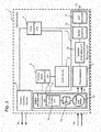
- the receiver unit 3 may further comprise a buffer amplifier 10 (providing electric impedance transformation from its input to its output) and an A/D converter 11.
- the components 7, 8, 9, 10, 11 of the receiver unit 3 are according to the illustrated exemplifying embodiment of the present invention arranged in series.
- the order of the receiver unit 3 components 7, 8, 9, 10, 11 in this series is not limited to the one shown in Fig. 1 but the order of the receiver unit 3 components 7, 8, 9, 10, 11 may in general be adjusted according to, e.g., user needs.
- the signal(s) 12 outputted from the receiver unit 3 may be supplied to other components for further analysis and/or processing.
- Fig. 1 and other appended drawings are schematic, and thus the relative positions of the components of the optical device 1 within the optical device 1 are shown by way of example and are not to be considering as limiting the present invention.
- the position of the optical radiation source 2 relative the receiver unit 3, or vice versa is not limited to the examples shown in the appended drawings.
- the optical device 1 may further include an optical system (not shown) configured to, e.g., collimate the emitted optical pulses 2a into a beam, the optical system comprising, e.g., one or more lens elements, prisms, wave guides, mirror elements, etc.
- the optical system comprising, e.g., one or more lens elements, prisms, wave guides, mirror elements, etc.
- an optical system is not critical to the implementation of the present invention as such and detailed description thereof is therefore omitted.
- various parameters of such an optical system may constitute a basis for determining or adapting a shape of a predetermined temporal function, on the basis of which predetermined temporal function one or more controls signals are generated by the control signal generator unit 5a, 5b, 5c.
- FIG. 2 there is shown a schematic block diagram of an optical device 1 according to another exemplifying embodiment of the present invention.
- the optical device 1 depicted in Fig. 2 comprises components similar to or the same as components comprised in the optical device 1 described with reference to Fig. 1 . The description of such similar or identical components with reference to Fig. 2 is therefore omitted.
- the optical device 1 comprises a single control signal generator unit 5 adapted to generate control signals, which control signal generator unit 5 may be controlled by the control unit 6, in accordance with the embodiment of the present invention depicted in Fig. 2 .
- control signal generator unit 5 may be controlled by the control unit 6, in accordance with the embodiment of the present invention depicted in Fig. 2 .
- FIG. 2 As illustrated in Fig.
- the optical device 1 may comprise a memory unit 13 adapted to store data.
- the control signal generator unit 5 may be adapted to generate control signals by retrieving control signal values that were previously stored in the memory unit 13.
- the memory unit 13 may for example comprise a flash memory or another type of non-volatile memory such as a ROM. Alternatively, the memory unit 13 may be arranged integral with the control signal generator 5.
- the receiver unit 2 described with reference to Fig. the receiver unit 2 described with reference to Fig.
- variable optical attenuator unit 14 that may have a momentarily varied optical attenuation, which optical attenuator unit 14 is configured to attenuate the received reflected optical pulses 3a, thus producing attenuated optical pulses 3b, and a variable attenuator unit 15, configured to attenuate electrical (return) signals that, as already mentioned above, may be generated by the photodetector 7 from optical pulses inputted to the photodetector 7.
- the control signal generator unit 5 may be connected to the receiver unit 3, meaning that the control signal generator unit 5 may be connected to any of the components comprised in the receiver unit 3. Accordingly, the control signal generator unit 5 may be adapted to generate control signals by which any of the components of the receiver unit 3 may be controlled or adjusted on the basis of the thus generated control signals, such as to adjust the total dynamic range of the receiver unit 3.
- FIG. 3 there is shown a schematic block diagram of an optical device 1 according to yet another exemplifying embodiment of the present invention.
- the optical device 1 depicted in Fig. 3 comprises components similar to or the same as components comprised in the optical device 1 described with reference to Figs. 1 and/or 2. The description of such similar or identical components with reference to Fig. 3 is therefore omitted.
- Fig. 3 in contrast to the optical device(s) 1 described with reference to Figs.
- the receiver unit 3 of the optical device 1 may comprise a variable optical attenuator unit 14 including, or being, a gray wedge unit 16, which in turn may comprise a rotatable gray wedge 17, arranged such that reflected optical pulses 3a at the receiver unit 3 may pass through the rotatable gray wedge 17 before reaching any other components of the receiver unit 3.
- the rotatable gray wedge 17 may comprise a plurality of angular sectors, each angular sector having a predetermined transmission coefficient.
- control signal generator unit 5 may be connected to the receiver unit 3 (meaning that the control signal generator unit 5 may be connected to any of the components comprised in the receiver unit 3, such as the optical attenuator unit 14). Accordingly, the control signal generator unit 5 may be adapted to generate control signals by which any of the components of the receiver unit 3 may be controlled or adjusted on the basis of the thus generated control signals, such as to adjust the total dynamic range of the receiver unit 3.
- Fig. 4 there is shown a schematic illustration of a rotatable gray wedge 17 according to an exemplifying embodiment of the present invention, wherein the rotatable gray wedge 17 comprises two angular sectors 17a, 17b.
- the angular sectors 17a, 17b may have different coefficients of transmission.
- the gray wedge unit 16 may further comprise a motor 18 arranged for rotating the gray wedge 17.
- the gray wedge unit 16 may further comprise a synchronization unit 19 adapted to synchronize the speed of rotation of the gray wedge 17 with a predetermined speed. This predetermined speed may be equal to the rate of emission of optical pulses 2a from the optical radiation source 2.
- the rotation speed of a gray wedge 17 having N angular segments may be decreased N times compared to the required rotation speed of a gray wedge 17 having only two angular segments in accordance with the exemplary embodiment of the present invention described with reference to Fig. 4 .
- Each angular sector 17a, 17b of the rotatable gray wedge 17 may comprise a plurality of angular subsectors (not shown), arranged such that the transmission coefficient of each angular subsector varies monotonically in an angular direction with respect to the gray wedge 17. In this way, the smoothness of the response of the variable optical attenuator unit 16 to the control signals may be improved.
- FIG. 5 there is shown a schematic block diagram of a distance measuring device 20 according to an exemplifying embodiment of the present invention.
- the distance measuring device 20 comprises an optical device 1, a few examples of which have been described herein.
- the distance measuring device 20 may comprise an optical device 1 according to any embodiment of the present invention as described herein and as defined by the appended claims.
- the distance measuring device 30 comprises a distance measuring device 20 such as described with reference to Fig. 5 .
- the surveying instrument 30 may comprise a distance measuring device 20 according to any embodiment of the present invention as described herein and as defined by the appended claims.
- FIG. 7 there is shown schematic views of computer readable digital storage mediums 41, 42 according to exemplifying embodiments of the present invention, comprising a DVD 41 and a floppy disk 42 on each of which there may be stored a computer program comprising computer code adapted to perform, when executed in a processor unit a method according to the present invention or embodiments thereof, as has been described in the foregoing.
- a computer program comprising computer code adapted to perform, when executed in a processor unit a method according to the present invention or embodiments thereof, as has been described in the foregoing.
- FIG. 7 the present invention encompasses embodiments employing any other suitable type of computer-readable digital storage medium, such as, but not limited to, a hard disk drive, a CD, a flash memory, magnetic tape, a USB stick, a Zip drive, etc.
- a computer program product comprising computer code adapted to perform, when executed in a processor unit, a method according to the present invention or any embodiment thereof may be stored on a computer (e.g. a server) adapted to be in communication with an optical device, a distance measuring device or a surveying instrument according to an exemplifying embodiment of the present invention.
- the computer program may perform the method.
- Such a configuration eliminates the need to store the computer program locally at the optical device, the distance measuring device or the surveying instrument.
- the communication between the computer and the optical device, the distance measuring device or the surveying instrument may be implemented in a wired fashion (e.g. by means of Ethernet) or in a non-wired fashion (e.g. by means of wireless infra-red (IR) communications or other wireless optical communications, or by means of wireless radiowave communications such as Global Positioning System (GPS)).
- IR infra-red
- GPS Global Positioning System
Landscapes
- Physics & Mathematics (AREA)
- Engineering & Computer Science (AREA)
- General Physics & Mathematics (AREA)
- Radar, Positioning & Navigation (AREA)
- Remote Sensing (AREA)
- Electromagnetism (AREA)
- Computer Networks & Wireless Communication (AREA)
- Optical Radar Systems And Details Thereof (AREA)
Claims (14)
- Instrument d'arpentage (30) incluant un dispositif de mesure de distance (20) pour mesurer une distance vers une cible depuis ledit dispositif de mesure de distance, dans lequel ledit dispositif de mesure de distance comprend :une unité de traitement adaptée pour déterminer la distance jusqu'à la cible à partir dudit dispositif de mesure de distance en se basant sur une comparaison entre une impulsion optique transmise et une impulsion optique reçue ; etun dispositif optique (1), incluant :une source de rayonnement optique (2) adaptée pour émettre des impulsions optiques ;une unité réceptrice (3) adaptée pour recevoir des impulsions optiques réfléchies ;une unité de mesure du temps (4) adaptée pour générer un temps écoulé à partir d'un point dans le temps prédéterminé ;au moins une unité génératrice de signaux de commande (5a, 5b, 5c) ; etune unité de commande (6) ;dans lequel l'unité de commande est adaptée pour :faire que l'au moins une unité génératrice de signaux de commande génère au moins un signal de commande selon une fonction temporelle prédéterminée en se basant sur le temps écoulé ; eten se basant sur l'au moins un signal de commande généré, ajuster au moins un paramètre de ladite unité réceptrice pendant un temps de déplacement d'une impulsion optique à partir du dispositif optique vers une cible et retour, dans lequel ledit au moins un paramètre affecte la plage dynamique de ladite unité réceptrice,caractérisé en ce que la fonction temporelle prédéterminée est configurée de telle façon qu'elle comprenne au moins en partie une forme qui est déterminée en se basant sur différents paramètres d'un système optique compris dans le dispositif optique, ledit système optique étant configuré pour diriger une partie des impulsions optiques réfléchies vers l'unité réceptrice ; etdans lequel la dépendance temporelle dudit au moins un paramètre de l'unité réceptrice, qui est la sensibilité optique de l'unité réceptrice, est étalonnée pendant ou après la fabrication du dispositif optique.
- Instrument d'arpentage selon la revendication 1, dans lequel le système optique inclut au moins un ou plusieurs éléments de lentilles, prismes, guides d'ondes et éléments de miroir.
- Instrument d'arpentage selon l'une quelconque des revendications précédentes, dans lequel l'unité réceptrice inclut une unité de photodétecteur (7) adaptée pour générer des signaux de retour électrique venant desdites impulsions optiques réfléchies, ladite unité réceptrice comprenant en outre une unité atténuatrice variable (15) configurée pour atténuer les signaux de retour électrique ou une unité atténuatrice optique variable (14) configurée pour atténuer lesdites impulsions optiques réfléchies, dans lequel ledit au moins un paramètre comprend l'atténuation de ladite unité atténuatrice variable ou ladite d'atténuateur optique variable.
- Instrument d'arpentage selon l'une quelconque des revendications précédentes, dans lequel ledit point dans le temps prédéterminé est un point dans le temps lorsque l'impulsion optique est émise, ou dans lequel ledit point dans le temps prédéterminé est un point dans le temps lorsqu'une impulsion de référence optique est reçue sur l'unité réceptrice, ladite impulsion de référence optique étant émise de façon concurrente avec ou en connexion avec l'émission de l'impulsion optique venant de la source de rayonnement optique.
- Instrument d'arpentage selon l'une quelconque des revendications précédentes, dans lequel ledit au moins un paramètre de ladite unité réceptrice comprend la sensibilité optique de l'unité de photodétecteur de ladite unité réceptrice.
- Instrument d'arpentage selon l'une quelconque des revendications précédentes, dans lequel l'unité réceptrice inclut :
une unité amplificatrice de gain variable (9) configurée pour amplifier les signaux de retour électrique, dans lequel ledit au moins un paramètre comprend le gain de ladite unité amplificatrice de gain variable. - Instrument d'arpentage selon l'une quelconque des revendications précédentes, dans lequel ladite unité de commande est en outre adaptée pour, si le temps écoulé dépasse un temps écoulé maximal prédéterminé, remettre l'unité de mesure du temps à zéro.
- Instrument d'arpentage selon la revendication 7, dans lequel le temps écoulé maximal prédéterminé est réglé sur la base du temps de déplacement maximal mesurable de l'au moins une impulsion optique à partir du point dans le temps prédéterminé.
- Instrument d'arpentage selon l'une quelconque des revendications précédentes, dans lequel ladite fonction temporelle prédéterminée correspond ou approxime essentiellement une fonction estimée de la puissance optique reçue contre le temps écoulé pour ladite impulsion optique ou correspond ou approxime essentiellement une inverse de ladite fonction estimée.
- Instrument d'arpentage selon l'une quelconque des revendications précédentes, dans lequel ladite fonction temporelle prédéterminée correspond ou approxime essentiellement une fonction estimée de la puissance optique reçue contre le temps écoulé pour une impulsion optique réfléchie à partir d'une cible ayant un albédo essentiellement constant ou correspond ou approxime essentiellement une inverse de ladite fonction estimée.
- Instrument d'arpentage selon l'une quelconque des revendications précédentes, dans lequel ladite fonction temporelle prédéterminée comprend au moins partiellement une forme selon une fonction en escalier, une fonction polynomiale, une fonction linéaire, une fonction quadratique, une fonction rectangulaire, une fonction qui se dégrade de façon exponentielle ou n'importe quelle combinaison de celles-ci.
- Instrument d'arpentage selon l'une quelconque des revendications précédentes, dans lequel l'unité génératrice de signaux de commande comprend une unité de mémoire (13) adaptée pour stocker des données, et l'unité génératrice de signaux de commande est adaptée pour générer des signaux de commande en récupérant des valeurs de signaux de commande stockés au préalable dans l'unité de mémoire.
- Instrument d'arpentage selon l'une quelconque des revendications précédentes, dans lequel le paramètre est l'atténuation ou l'amplification de ladite unité réceptrice et l'unité de commande est configurée pour régler l'atténuation ou l'amplification de ladite unité réceptrice à une valeur haute ou une valeur basse, respectivement, à l'instant où l'impulsion optique est émise de la source de rayonnement optique, puis, immédiatement après que l'impulsion optique a été émise, à mesure que le temps écoulé augmente, baisser ou augmenter, respectivement, l'atténuation ou l'amplification, respectivement, temporairement en se basant sur l'au moins un signal de commande généré jusqu'à ce qu'une autre impulsion soit émise de la source de rayonnement optique.
- Procédé pour le fonctionnement d'un instrument d'arpentage (30) incluant un dispositif de mesure de distance (20) comprenant un dispositif optique (1) et une unité de traitement,dans lequel l'unité de traitement est adaptée pour déterminer la distance jusqu'à une cible à partir dudit dispositif de mesure de distance en se basant sur une comparaison entre une impulsion optique transmise et une impulsion optique reçue,dans lequel le dispositif optique (1) comprend une source de rayonnement optique (2) adaptée pour émettre des impulsions optiques, une unité réceptrice (3) adaptée pour recevoir des impulsions optiques réfléchies, une unité de mesure du temps (4) adaptée pour générer un temps écoulé d'au moins une impulsion optique, l'unité de mesure du temps étant configurée de façon à ce que ledit temps écoulé soit généré à partir d'un point dans le temps prédéterminé, et au moins une unité génératrice de signaux de commande, le procédé comprenant :de faire que l'au moins une unité génératrice de signaux de commande génère au moins un signal de commande selon une fonction temporelle prédéterminée en se basant sur le temps écoulé ; eten se basant sur l'au moins un signal de commande généré, d'ajuster au moins un paramètre de ladite unité réceptrice pendant un temps de déplacement d'une impulsion optique à partir du dispositif optique vers une cible et retour, dans lequel ledit au moins un paramètre affecte la plage dynamique de ladite unité réceptrice,caractérisé en ce que la fonction temporelle prédéterminée est configurée de telle façon qu'elle comprenne au moins en partie une forme qui est déterminée en se basant sur différents paramètres d'un système optique compris dans le dispositif optique, le système optique étant configuré pour diriger une partie des impulsions optiques réfléchies vers l'unité réceptrice ; etdans lequel la dépendance temporelle dudit au moins un paramètre de l'unité réceptrice, qui est la sensibilité optique de l'unité réceptrice, est étalonnée pendant ou après la fabrication du dispositif optique.
Priority Applications (1)
| Application Number | Priority Date | Filing Date | Title |
|---|---|---|---|
| EP15184707.6A EP3009859B1 (fr) | 2009-06-26 | 2009-06-26 | Dispositif de mesure de distance |
Applications Claiming Priority (3)
| Application Number | Priority Date | Filing Date | Title |
|---|---|---|---|
| EP15184707.6A EP3009859B1 (fr) | 2009-06-26 | 2009-06-26 | Dispositif de mesure de distance |
| PCT/EP2009/058051 WO2010149219A1 (fr) | 2009-06-26 | 2009-06-26 | Dispositif de mesure de distance |
| EP09779974A EP2446296A1 (fr) | 2009-06-26 | 2009-06-26 | Dispositif de mesure de distance |
Related Parent Applications (1)
| Application Number | Title | Priority Date | Filing Date |
|---|---|---|---|
| EP09779974A Division EP2446296A1 (fr) | 2009-06-26 | 2009-06-26 | Dispositif de mesure de distance |
Publications (2)
| Publication Number | Publication Date |
|---|---|
| EP3009859A1 EP3009859A1 (fr) | 2016-04-20 |
| EP3009859B1 true EP3009859B1 (fr) | 2021-09-08 |
Family
ID=41508929
Family Applications (2)
| Application Number | Title | Priority Date | Filing Date |
|---|---|---|---|
| EP15184707.6A Active EP3009859B1 (fr) | 2009-06-26 | 2009-06-26 | Dispositif de mesure de distance |
| EP09779974A Ceased EP2446296A1 (fr) | 2009-06-26 | 2009-06-26 | Dispositif de mesure de distance |
Family Applications After (1)
| Application Number | Title | Priority Date | Filing Date |
|---|---|---|---|
| EP09779974A Ceased EP2446296A1 (fr) | 2009-06-26 | 2009-06-26 | Dispositif de mesure de distance |
Country Status (4)
| Country | Link |
|---|---|
| US (3) | US8755037B2 (fr) |
| EP (2) | EP3009859B1 (fr) |
| CN (1) | CN102460209B (fr) |
| WO (1) | WO2010149219A1 (fr) |
Families Citing this family (38)
| Publication number | Priority date | Publication date | Assignee | Title |
|---|---|---|---|---|
| US9157989B2 (en) | 2012-08-29 | 2015-10-13 | Trimble Ab | Distance measurement methods and apparatus |
| WO2014067579A1 (fr) * | 2012-11-01 | 2014-05-08 | Trimble Ab | Unité de suiveur et procédé dans une unité de suiveur |
| JP6045963B2 (ja) * | 2013-04-05 | 2016-12-14 | 日立マクセル株式会社 | 光測距装置 |
| CN106062511B (zh) * | 2013-12-05 | 2018-12-04 | 特林布尔有限公司 | 大地测量仪器和操作大地测量仪器的方法 |
| US9684070B2 (en) * | 2013-12-20 | 2017-06-20 | Delta Mobile Systems, Inc | Radar apparatus with quiet switch calibration and associated methods |
| US10291329B2 (en) * | 2013-12-20 | 2019-05-14 | Infineon Technologies Ag | Exchanging information between time-of-flight ranging devices |
| EP2937665B1 (fr) * | 2014-04-23 | 2021-06-16 | Hexagon Technology Center GmbH | Module de mesure de distance doté d'une unité d'atténuation optique variable à partir d'une cellule LC |
| CN106461780B (zh) * | 2014-05-28 | 2019-06-18 | 特林布尔有限公司 | 补偿的距离测量的方法和装置 |
| WO2016101973A1 (fr) * | 2014-12-22 | 2016-06-30 | Trimble Ab | Instrument de mesure de distance |
| JP2017003461A (ja) * | 2015-06-11 | 2017-01-05 | 東芝テック株式会社 | 距離測定装置 |
| US9823118B2 (en) | 2015-12-26 | 2017-11-21 | Intel Corporation | Low power, high resolution solid state LIDAR circuit |
| JP6867733B2 (ja) | 2016-03-31 | 2021-05-12 | 株式会社トプコン | レーザスキャナ |
| JP2018013333A (ja) * | 2016-07-19 | 2018-01-25 | 大成建設株式会社 | 計測管理システム |
| US10422865B2 (en) * | 2016-09-07 | 2019-09-24 | Qualcomm Incorporated | Time-dependent filtering for lidar signals |
| GB2565029A (en) * | 2017-01-10 | 2019-02-06 | Jt Networks Ltd | Surveying target assembly |
| US10139478B2 (en) * | 2017-03-28 | 2018-11-27 | Luminar Technologies, Inc. | Time varying gain in an optical detector operating in a lidar system |
| CN108401444B (zh) * | 2017-03-29 | 2022-07-08 | 深圳市大疆创新科技有限公司 | 一种激光雷达以及基于激光雷达的时间测量方法 |
| WO2019079642A1 (fr) * | 2017-10-19 | 2019-04-25 | Innovusion Ireland Limited | Lidar à plage dynamique étendue |
| CN108646252B (zh) * | 2017-12-25 | 2022-02-22 | 深圳天眼激光科技有限公司 | 一种脉冲激光回波信号调理电路及脉冲式激光扫描系统 |
| US11415678B2 (en) * | 2018-01-12 | 2022-08-16 | Analog Devices International Unlimited Company | Receiver with tunable filter for light range finding system |
| US11536805B2 (en) | 2018-06-25 | 2022-12-27 | Silc Technologies, Inc. | Optical switching for tuning direction of LIDAR output signals |
| US12535586B2 (en) | 2018-08-31 | 2026-01-27 | SiLC Technology, Inc. | Reduction of ADC sampling rates in LIDAR systems |
| US11703590B2 (en) | 2018-11-19 | 2023-07-18 | Suteng Innovation Technology Co., Ltd. | Lidar signal receiving circuits, lidar signal gain control methods, and lidars using the same |
| US12429569B2 (en) | 2019-05-17 | 2025-09-30 | Silc Technologies, Inc. | Identification of materials illuminated by LIDAR systems |
| US11650317B2 (en) | 2019-06-28 | 2023-05-16 | Silc Technologies, Inc. | Use of frequency offsets in generation of LIDAR data |
| US11714167B2 (en) * | 2019-08-21 | 2023-08-01 | Silc Technologies, Inc. | LIDAR adapter for use with LIDAR chip |
| CN110850427B (zh) * | 2019-11-26 | 2022-06-14 | 上海禾赛科技有限公司 | 可用于激光雷达的放大电路、激光雷达、控制方法 |
| US12000931B2 (en) | 2020-05-15 | 2024-06-04 | Analog Devices International Unlimited Company | Continuous wave time of flight system |
| US12306349B2 (en) * | 2020-05-15 | 2025-05-20 | Analog Devices International Unlimited Company | Proximity detection system |
| US12541009B2 (en) | 2021-06-17 | 2026-02-03 | Silc Technologies, Inc. | Scanning multiple LIDAR system output signals |
| US11555902B1 (en) | 2021-07-09 | 2023-01-17 | Aeva, Inc. | Techniques for automatic gain control in a frequency domain for a signal path for a frequency modulated continuous wave (FMCW) light detection and ranging (LIDAR) system |
| US12411213B2 (en) | 2021-10-11 | 2025-09-09 | Silc Technologies, Inc. | Separation of light signals in a LIDAR system |
| US12553995B2 (en) | 2022-02-14 | 2026-02-17 | Silc Technologies, Inc. | Data refinement in optical systems |
| US12578443B2 (en) | 2022-04-23 | 2026-03-17 | Silc Technologies, Inc. | Data refinement in optical imaging systems |
| US12505675B2 (en) | 2022-06-28 | 2025-12-23 | Trimble Inc. | Automatic optimization of obstacle detection |
| US20240085559A1 (en) * | 2022-09-14 | 2024-03-14 | Silc Technologies, Inc. | Combining data from different sample regions in an imaging system field of view |
| US12422618B2 (en) | 2022-10-13 | 2025-09-23 | Silc Technologies, Inc. | Buried taper with reflecting surface |
| US12578439B2 (en) | 2023-04-11 | 2026-03-17 | Silc Technologies, Inc. | Increasing resolution in imaging systems |
Family Cites Families (12)
| Publication number | Priority date | Publication date | Assignee | Title |
|---|---|---|---|---|
| US587785A (en) | 1897-08-10 | broughton | ||
| US3721837A (en) * | 1971-07-06 | 1973-03-20 | Gen Electric | Tunnel diode supply voltage control |
| US5646623A (en) * | 1978-05-15 | 1997-07-08 | Walters; Glenn A. | Coherent, frequency multiplexed radar |
| US4498764A (en) | 1981-06-09 | 1985-02-12 | Ludwig Bolkow | Dynamic control arrangement for a distance measuring apparatus |
| EP0366189A3 (fr) | 1988-10-24 | 1992-01-02 | Norwich Eaton Pharmaceuticals, Inc. | Lactames-quinolones antimicrobiennes |
| DE3922429C1 (fr) * | 1989-07-07 | 1991-01-24 | Deutsche Forschungsanstalt Fuer Luft- Und Raumfahrt Ev, 5300 Bonn, De | |
| CN1110398A (zh) * | 1993-12-27 | 1995-10-18 | 现代电子产业株式会社 | 光学测距装置及其方法 |
| US5877851A (en) * | 1997-09-24 | 1999-03-02 | The United States Of America As Represented By The Secretary Of The Army | Scannerless ladar architecture employing focal plane detector arrays and FM-CW ranging theory |
| JP2003167054A (ja) * | 2001-12-04 | 2003-06-13 | Denso Corp | 距離測定方法及び距離測定装置 |
| US20030175001A1 (en) * | 2002-03-18 | 2003-09-18 | Lawrence Brian L. | Variable fiber optic attenuator |
| SE525290C2 (sv) | 2002-12-20 | 2005-01-25 | Trimble Ab | Geodetiskt system för mätning/utsättning och metod för användning av detsamma |
| EP1882959A1 (fr) | 2006-07-17 | 2008-01-30 | Leica Geosystems AG | Procédé de mesure de distance optique et télémètre optique correspondant |
-
2009
- 2009-06-26 EP EP15184707.6A patent/EP3009859B1/fr active Active
- 2009-06-26 CN CN200980160000.5A patent/CN102460209B/zh active Active
- 2009-06-26 US US13/376,241 patent/US8755037B2/en active Active
- 2009-06-26 EP EP09779974A patent/EP2446296A1/fr not_active Ceased
- 2009-06-26 WO PCT/EP2009/058051 patent/WO2010149219A1/fr not_active Ceased
-
2014
- 2014-04-29 US US14/264,589 patent/US9267796B2/en active Active
-
2016
- 2016-02-17 US US15/045,730 patent/US9519052B2/en active Active
Also Published As
| Publication number | Publication date |
|---|---|
| US20160231419A1 (en) | 2016-08-11 |
| US8755037B2 (en) | 2014-06-17 |
| US20140233012A1 (en) | 2014-08-21 |
| US9519052B2 (en) | 2016-12-13 |
| CN102460209B (zh) | 2016-01-20 |
| WO2010149219A1 (fr) | 2010-12-29 |
| EP3009859A1 (fr) | 2016-04-20 |
| CN102460209A (zh) | 2012-05-16 |
| EP2446296A1 (fr) | 2012-05-02 |
| US9267796B2 (en) | 2016-02-23 |
| US20120140203A1 (en) | 2012-06-07 |
Similar Documents
| Publication | Publication Date | Title |
|---|---|---|
| EP3009859B1 (fr) | Dispositif de mesure de distance | |
| US10302747B2 (en) | Distance measuring apparatus, electronic device, method for measuring distance, and recording medium | |
| CN108415028B (zh) | 脉冲参数加密的激光测距系统及方法 | |
| US8149391B2 (en) | Distance measuring instrument and method | |
| DK2486412T3 (en) | Device for measuring wind speed | |
| EP2375265A1 (fr) | Dispositif et procédé de mesure de distance | |
| CN210142193U (zh) | 一种测距装置、移动平台 | |
| US10281578B2 (en) | Compensated distance measurement methods and apparatus | |
| CN113419250B (zh) | 激光测距系统及激光测距方法 | |
| US10816646B2 (en) | Distance measurement instrument | |
| US8995577B2 (en) | Apparatus and method for measurement of the reception time of a pulse | |
| CN116679310A (zh) | Fmcw激光测量装置 | |
| CN104777471B (zh) | 一种脉冲激光近程动态增益控制电路 | |
| CN112219330A (zh) | 一种激光接收电路及测距装置、移动平台 | |
| CN114355362B (zh) | 激光雷达系统及光纤传感系统的自发辐射噪声的拟合方法 | |
| JP7098971B2 (ja) | 測距装置及び測距方法 | |
| KR102480883B1 (ko) | 차량용 라이다 센서 | |
| CN119805472A (zh) | 激光定位方法、处理芯片单元以及激光定位系统 |
Legal Events
| Date | Code | Title | Description |
|---|---|---|---|
| PUAI | Public reference made under article 153(3) epc to a published international application that has entered the european phase |
Free format text: ORIGINAL CODE: 0009012 |
|
| AC | Divisional application: reference to earlier application |
Ref document number: 2446296 Country of ref document: EP Kind code of ref document: P |
|
| AK | Designated contracting states |
Kind code of ref document: A1 Designated state(s): AT BE BG CH CY CZ DE DK EE ES FI FR GB GR HR HU IE IS IT LI LT LU LV MC MK MT NL NO PL PT RO SE SI SK TR |
|
| 17P | Request for examination filed |
Effective date: 20161017 |
|
| RBV | Designated contracting states (corrected) |
Designated state(s): AT BE BG CH CY CZ DE DK EE ES FI FR GB GR HR HU IE IS IT LI LT LU LV MC MK MT NL NO PL PT RO SE SI SK TR |
|
| STAA | Information on the status of an ep patent application or granted ep patent |
Free format text: STATUS: EXAMINATION IS IN PROGRESS |
|
| 17Q | First examination report despatched |
Effective date: 20180516 |
|
| GRAP | Despatch of communication of intention to grant a patent |
Free format text: ORIGINAL CODE: EPIDOSNIGR1 |
|
| STAA | Information on the status of an ep patent application or granted ep patent |
Free format text: STATUS: GRANT OF PATENT IS INTENDED |
|
| INTG | Intention to grant announced |
Effective date: 20210510 |
|
| GRAS | Grant fee paid |
Free format text: ORIGINAL CODE: EPIDOSNIGR3 |
|
| GRAA | (expected) grant |
Free format text: ORIGINAL CODE: 0009210 |
|
| STAA | Information on the status of an ep patent application or granted ep patent |
Free format text: STATUS: THE PATENT HAS BEEN GRANTED |
|
| AC | Divisional application: reference to earlier application |
Ref document number: 2446296 Country of ref document: EP Kind code of ref document: P |
|
| AK | Designated contracting states |
Kind code of ref document: B1 Designated state(s): AT BE BG CH CY CZ DE DK EE ES FI FR GB GR HR HU IE IS IT LI LT LU LV MC MK MT NL NO PL PT RO SE SI SK TR |
|
| REG | Reference to a national code |
Ref country code: GB Ref legal event code: FG4D |
|
| REG | Reference to a national code |
Ref country code: CH Ref legal event code: EP Ref country code: AT Ref legal event code: REF Ref document number: 1429043 Country of ref document: AT Kind code of ref document: T Effective date: 20210915 |
|
| REG | Reference to a national code |
Ref country code: DE Ref legal event code: R096 Ref document number: 602009064022 Country of ref document: DE |
|
| REG | Reference to a national code |
Ref country code: IE Ref legal event code: FG4D |
|
| REG | Reference to a national code |
Ref country code: LT Ref legal event code: MG9D |
|
| REG | Reference to a national code |
Ref country code: NL Ref legal event code: MP Effective date: 20210908 |
|
| PG25 | Lapsed in a contracting state [announced via postgrant information from national office to epo] |
Ref country code: SE Free format text: LAPSE BECAUSE OF FAILURE TO SUBMIT A TRANSLATION OF THE DESCRIPTION OR TO PAY THE FEE WITHIN THE PRESCRIBED TIME-LIMIT Effective date: 20210908 Ref country code: HR Free format text: LAPSE BECAUSE OF FAILURE TO SUBMIT A TRANSLATION OF THE DESCRIPTION OR TO PAY THE FEE WITHIN THE PRESCRIBED TIME-LIMIT Effective date: 20210908 Ref country code: NO Free format text: LAPSE BECAUSE OF FAILURE TO SUBMIT A TRANSLATION OF THE DESCRIPTION OR TO PAY THE FEE WITHIN THE PRESCRIBED TIME-LIMIT Effective date: 20211208 Ref country code: FI Free format text: LAPSE BECAUSE OF FAILURE TO SUBMIT A TRANSLATION OF THE DESCRIPTION OR TO PAY THE FEE WITHIN THE PRESCRIBED TIME-LIMIT Effective date: 20210908 Ref country code: ES Free format text: LAPSE BECAUSE OF FAILURE TO SUBMIT A TRANSLATION OF THE DESCRIPTION OR TO PAY THE FEE WITHIN THE PRESCRIBED TIME-LIMIT Effective date: 20210908 Ref country code: LT Free format text: LAPSE BECAUSE OF FAILURE TO SUBMIT A TRANSLATION OF THE DESCRIPTION OR TO PAY THE FEE WITHIN THE PRESCRIBED TIME-LIMIT Effective date: 20210908 Ref country code: BG Free format text: LAPSE BECAUSE OF FAILURE TO SUBMIT A TRANSLATION OF THE DESCRIPTION OR TO PAY THE FEE WITHIN THE PRESCRIBED TIME-LIMIT Effective date: 20211208 |
|
| REG | Reference to a national code |
Ref country code: AT Ref legal event code: MK05 Ref document number: 1429043 Country of ref document: AT Kind code of ref document: T Effective date: 20210908 |
|
| PG25 | Lapsed in a contracting state [announced via postgrant information from national office to epo] |
Ref country code: LV Free format text: LAPSE BECAUSE OF FAILURE TO SUBMIT A TRANSLATION OF THE DESCRIPTION OR TO PAY THE FEE WITHIN THE PRESCRIBED TIME-LIMIT Effective date: 20210908 Ref country code: GR Free format text: LAPSE BECAUSE OF FAILURE TO SUBMIT A TRANSLATION OF THE DESCRIPTION OR TO PAY THE FEE WITHIN THE PRESCRIBED TIME-LIMIT Effective date: 20211209 |
|
| PG25 | Lapsed in a contracting state [announced via postgrant information from national office to epo] |
Ref country code: AT Free format text: LAPSE BECAUSE OF FAILURE TO SUBMIT A TRANSLATION OF THE DESCRIPTION OR TO PAY THE FEE WITHIN THE PRESCRIBED TIME-LIMIT Effective date: 20210908 |
|
| PG25 | Lapsed in a contracting state [announced via postgrant information from national office to epo] |
Ref country code: IS Free format text: LAPSE BECAUSE OF FAILURE TO SUBMIT A TRANSLATION OF THE DESCRIPTION OR TO PAY THE FEE WITHIN THE PRESCRIBED TIME-LIMIT Effective date: 20220108 Ref country code: SK Free format text: LAPSE BECAUSE OF FAILURE TO SUBMIT A TRANSLATION OF THE DESCRIPTION OR TO PAY THE FEE WITHIN THE PRESCRIBED TIME-LIMIT Effective date: 20210908 Ref country code: RO Free format text: LAPSE BECAUSE OF FAILURE TO SUBMIT A TRANSLATION OF THE DESCRIPTION OR TO PAY THE FEE WITHIN THE PRESCRIBED TIME-LIMIT Effective date: 20210908 Ref country code: PT Free format text: LAPSE BECAUSE OF FAILURE TO SUBMIT A TRANSLATION OF THE DESCRIPTION OR TO PAY THE FEE WITHIN THE PRESCRIBED TIME-LIMIT Effective date: 20220110 Ref country code: PL Free format text: LAPSE BECAUSE OF FAILURE TO SUBMIT A TRANSLATION OF THE DESCRIPTION OR TO PAY THE FEE WITHIN THE PRESCRIBED TIME-LIMIT Effective date: 20210908 Ref country code: NL Free format text: LAPSE BECAUSE OF FAILURE TO SUBMIT A TRANSLATION OF THE DESCRIPTION OR TO PAY THE FEE WITHIN THE PRESCRIBED TIME-LIMIT Effective date: 20210908 Ref country code: EE Free format text: LAPSE BECAUSE OF FAILURE TO SUBMIT A TRANSLATION OF THE DESCRIPTION OR TO PAY THE FEE WITHIN THE PRESCRIBED TIME-LIMIT Effective date: 20210908 Ref country code: CZ Free format text: LAPSE BECAUSE OF FAILURE TO SUBMIT A TRANSLATION OF THE DESCRIPTION OR TO PAY THE FEE WITHIN THE PRESCRIBED TIME-LIMIT Effective date: 20210908 |
|
| REG | Reference to a national code |
Ref country code: DE Ref legal event code: R097 Ref document number: 602009064022 Country of ref document: DE |
|
| PLBE | No opposition filed within time limit |
Free format text: ORIGINAL CODE: 0009261 |
|
| STAA | Information on the status of an ep patent application or granted ep patent |
Free format text: STATUS: NO OPPOSITION FILED WITHIN TIME LIMIT |
|
| PG25 | Lapsed in a contracting state [announced via postgrant information from national office to epo] |
Ref country code: DK Free format text: LAPSE BECAUSE OF FAILURE TO SUBMIT A TRANSLATION OF THE DESCRIPTION OR TO PAY THE FEE WITHIN THE PRESCRIBED TIME-LIMIT Effective date: 20210908 |
|
| 26N | No opposition filed |
Effective date: 20220609 |
|
| PG25 | Lapsed in a contracting state [announced via postgrant information from national office to epo] |
Ref country code: SI Free format text: LAPSE BECAUSE OF FAILURE TO SUBMIT A TRANSLATION OF THE DESCRIPTION OR TO PAY THE FEE WITHIN THE PRESCRIBED TIME-LIMIT Effective date: 20210908 |
|
| PG25 | Lapsed in a contracting state [announced via postgrant information from national office to epo] |
Ref country code: MC Free format text: LAPSE BECAUSE OF FAILURE TO SUBMIT A TRANSLATION OF THE DESCRIPTION OR TO PAY THE FEE WITHIN THE PRESCRIBED TIME-LIMIT Effective date: 20210908 Ref country code: IT Free format text: LAPSE BECAUSE OF FAILURE TO SUBMIT A TRANSLATION OF THE DESCRIPTION OR TO PAY THE FEE WITHIN THE PRESCRIBED TIME-LIMIT Effective date: 20210908 |
|
| REG | Reference to a national code |
Ref country code: CH Ref legal event code: PL |
|
| REG | Reference to a national code |
Ref country code: BE Ref legal event code: MM Effective date: 20220630 |
|
| GBPC | Gb: european patent ceased through non-payment of renewal fee |
Effective date: 20220626 |
|
| PG25 | Lapsed in a contracting state [announced via postgrant information from national office to epo] |
Ref country code: LU Free format text: LAPSE BECAUSE OF NON-PAYMENT OF DUE FEES Effective date: 20220626 Ref country code: LI Free format text: LAPSE BECAUSE OF NON-PAYMENT OF DUE FEES Effective date: 20220630 Ref country code: IE Free format text: LAPSE BECAUSE OF NON-PAYMENT OF DUE FEES Effective date: 20220626 Ref country code: FR Free format text: LAPSE BECAUSE OF NON-PAYMENT OF DUE FEES Effective date: 20220630 Ref country code: CH Free format text: LAPSE BECAUSE OF NON-PAYMENT OF DUE FEES Effective date: 20220630 |
|
| PG25 | Lapsed in a contracting state [announced via postgrant information from national office to epo] |
Ref country code: BE Free format text: LAPSE BECAUSE OF NON-PAYMENT OF DUE FEES Effective date: 20220630 Ref country code: GB Free format text: LAPSE BECAUSE OF NON-PAYMENT OF DUE FEES Effective date: 20220626 |
|
| PG25 | Lapsed in a contracting state [announced via postgrant information from national office to epo] |
Ref country code: HU Free format text: LAPSE BECAUSE OF FAILURE TO SUBMIT A TRANSLATION OF THE DESCRIPTION OR TO PAY THE FEE WITHIN THE PRESCRIBED TIME-LIMIT; INVALID AB INITIO Effective date: 20090626 |
|
| PG25 | Lapsed in a contracting state [announced via postgrant information from national office to epo] |
Ref country code: MK Free format text: LAPSE BECAUSE OF FAILURE TO SUBMIT A TRANSLATION OF THE DESCRIPTION OR TO PAY THE FEE WITHIN THE PRESCRIBED TIME-LIMIT Effective date: 20210908 Ref country code: CY Free format text: LAPSE BECAUSE OF FAILURE TO SUBMIT A TRANSLATION OF THE DESCRIPTION OR TO PAY THE FEE WITHIN THE PRESCRIBED TIME-LIMIT Effective date: 20210908 |
|
| PG25 | Lapsed in a contracting state [announced via postgrant information from national office to epo] |
Ref country code: MT Free format text: LAPSE BECAUSE OF FAILURE TO SUBMIT A TRANSLATION OF THE DESCRIPTION OR TO PAY THE FEE WITHIN THE PRESCRIBED TIME-LIMIT Effective date: 20210908 |
|
| PGFP | Annual fee paid to national office [announced via postgrant information from national office to epo] |
Ref country code: DE Payment date: 20250626 Year of fee payment: 17 |
|
| PG25 | Lapsed in a contracting state [announced via postgrant information from national office to epo] |
Ref country code: TR Free format text: LAPSE BECAUSE OF FAILURE TO SUBMIT A TRANSLATION OF THE DESCRIPTION OR TO PAY THE FEE WITHIN THE PRESCRIBED TIME-LIMIT Effective date: 20210908 |