EP3012071A1 - Drucklufthammer - Google Patents
Drucklufthammer Download PDFInfo
- Publication number
- EP3012071A1 EP3012071A1 EP15190218.6A EP15190218A EP3012071A1 EP 3012071 A1 EP3012071 A1 EP 3012071A1 EP 15190218 A EP15190218 A EP 15190218A EP 3012071 A1 EP3012071 A1 EP 3012071A1
- Authority
- EP
- European Patent Office
- Prior art keywords
- gear
- ring gear
- rotation
- housing
- respect
- Prior art date
- Legal status (The legal status is an assumption and is not a legal conclusion. Google has not performed a legal analysis and makes no representation as to the accuracy of the status listed.)
- Granted
Links
Images
Classifications
-
- B—PERFORMING OPERATIONS; TRANSPORTING
- B25—HAND TOOLS; PORTABLE POWER-DRIVEN TOOLS; MANIPULATORS
- B25D—PERCUSSIVE TOOLS
- B25D16/00—Portable percussive machines with superimposed rotation, the rotational movement of the output shaft of a motor being modified to generate axial impacts on the tool bit
- B25D16/006—Mode changers; Mechanisms connected thereto
-
- B—PERFORMING OPERATIONS; TRANSPORTING
- B25—HAND TOOLS; PORTABLE POWER-DRIVEN TOOLS; MANIPULATORS
- B25F—COMBINATION OR MULTI-PURPOSE TOOLS NOT OTHERWISE PROVIDED FOR; DETAILS OR COMPONENTS OF PORTABLE POWER-DRIVEN TOOLS NOT PARTICULARLY RELATED TO THE OPERATIONS PERFORMED AND NOT OTHERWISE PROVIDED FOR
- B25F5/00—Details or components of portable power-driven tools not particularly related to the operations performed and not otherwise provided for
- B25F5/001—Gearings, speed selectors, clutches or the like specially adapted for rotary tools
-
- B—PERFORMING OPERATIONS; TRANSPORTING
- B25—HAND TOOLS; PORTABLE POWER-DRIVEN TOOLS; MANIPULATORS
- B25D—PERCUSSIVE TOOLS
- B25D2211/00—Details of portable percussive tools with electromotor or other motor drive
- B25D2211/06—Means for driving the impulse member
- B25D2211/068—Crank-actuated impulse-driving mechanisms
-
- B—PERFORMING OPERATIONS; TRANSPORTING
- B25—HAND TOOLS; PORTABLE POWER-DRIVEN TOOLS; MANIPULATORS
- B25D—PERCUSSIVE TOOLS
- B25D2216/00—Details of portable percussive machines with superimposed rotation, the rotational movement of the output shaft of a motor being modified to generate axial impacts on the tool bit
- B25D2216/0007—Details of percussion or rotation modes
- B25D2216/0015—Tools having a percussion-only mode
-
- B—PERFORMING OPERATIONS; TRANSPORTING
- B25—HAND TOOLS; PORTABLE POWER-DRIVEN TOOLS; MANIPULATORS
- B25D—PERCUSSIVE TOOLS
- B25D2216/00—Details of portable percussive machines with superimposed rotation, the rotational movement of the output shaft of a motor being modified to generate axial impacts on the tool bit
- B25D2216/0007—Details of percussion or rotation modes
- B25D2216/0023—Tools having a percussion-and-rotation mode
-
- B—PERFORMING OPERATIONS; TRANSPORTING
- B25—HAND TOOLS; PORTABLE POWER-DRIVEN TOOLS; MANIPULATORS
- B25D—PERCUSSIVE TOOLS
- B25D2216/00—Details of portable percussive machines with superimposed rotation, the rotational movement of the output shaft of a motor being modified to generate axial impacts on the tool bit
- B25D2216/0007—Details of percussion or rotation modes
- B25D2216/0038—Tools having a rotation-only mode
-
- B—PERFORMING OPERATIONS; TRANSPORTING
- B25—HAND TOOLS; PORTABLE POWER-DRIVEN TOOLS; MANIPULATORS
- B25D—PERCUSSIVE TOOLS
- B25D2216/00—Details of portable percussive machines with superimposed rotation, the rotational movement of the output shaft of a motor being modified to generate axial impacts on the tool bit
- B25D2216/0007—Details of percussion or rotation modes
- B25D2216/0046—Preventing rotation
-
- B—PERFORMING OPERATIONS; TRANSPORTING
- B25—HAND TOOLS; PORTABLE POWER-DRIVEN TOOLS; MANIPULATORS
- B25D—PERCUSSIVE TOOLS
- B25D2216/00—Details of portable percussive machines with superimposed rotation, the rotational movement of the output shaft of a motor being modified to generate axial impacts on the tool bit
- B25D2216/0084—Mode-changing mechanisms
- B25D2216/0092—Tool comprising two or more collaborating mode-changing mechanisms
Definitions
- the present invention relates to a pneumatic hammer comprising a housing, a drive motor arranged in the housing, an output spindle supporting a tool holder for a tool bit, a hammer mechanism comprising a cylinder in which a reciprocatingly driven piston and a ram are arranged wherein in the cylinder an air cushion is formed between the piston and the ram so that the ram reciprocates upon reciprocating movement of the piston and imparts impacts on a tool bit supported in the tool holder, a conversion mechanism comprising a rotatable input member coupled to the drive motor and being adapted to convert a rotational movement of the input member into a reciprocating movement of an output member which is coupled with the piston, wherein the spindle is coupled with a rotatable drive member coupled with the drive motor so that rotation of the drive member effects rotation of the spindle.
- the hammer mechanism comprises a cylinder in which a piston and a ram are slidably supported so that they may conduct a sliding movement along a longitudinal axis of the cylinder.
- the ram may directly or indirectly, via a beat piece, get into contact with the rear end of a tool bit so as to impart axial impacts on the tool bit.
- an air cushion is formed between the piston and the ram, and the piston is reciprocatingly driven by a conversion mechanism which converts a rotational movement generated by a drive motor into a reciprocating movement.
- Such mechanisms are well known, e.g. wobble drive mechanisms and crank drive mechanisms.
- the latter employ a crank plate which is rotationally driven and provided with an eccentrically arranged crank pin. That pin is connected to the rear end of the piston by a connecting rod so that rotation of the crank plate effects a reciprocating motion of the piston. This motion is transferred to the ram via the air cushion between the piston and the ram so that the ram conducts a reciprocating movement as well.
- the forward movement it collides directly or indirectly with the rear end of the tool bit which is axially slidable supported in the tool holder.
- the output spindle on which the tool holder is supported and to which the cylinder is connected may also be rotationally driven, so as to allow for a drilling operation of the tool bit.
- Such hammers allow for different modes of operation such as a hammer drill mode in which the tool bit supported in the tool holder is rotationally driven and at the same time axial impacts are imparted on the tool bit via the hammer mechanism. Further, in a drilling mode, the hammer mechanism is deactivated so that the tool bit is rotationally driven only. Finally, such hammers also allow for a chisel mode in which only axial impacts are imparted on the tool bit by the hammer mechanism whereas the tool bit is not rotationally driven.
- hammers may be operated such that the output spindle may rotate in forward and reverse directions. This is for example advantageous if the tool bit must be retracted from a workpiece.
- the drive motor is capable of driving the armature in different rotational directions. In case of a brushed motor this requires that e.g. a corresponding mechanical assembly is provided which allows to switch between different angular positions of the brush support with respect to the stator.
- a brushless motor is another option which is to employ a brushless motor but in this case the electronics need to be adapted correspondingly.
- gear set is designed such that it has different settings for forward and reverse rotation.
- gear set is designed such that it has different settings for forward and reverse rotation.
- a separate stage in the gear set is disadvantageous both from a cost perspective and in view of the additional weight and space required.
- a pneumatic hammer comprising:
- the first ring gear is axially movable between a first position and a second position.
- the first ring gear In the first position the first ring gear is either fixed or freely rotatable and does not engage with the second gear whereas in the second position it meshingly engages with the second gear that is coupled with the spindle.
- the conventional modes of operation of a pneumatic hammer can be selected by the mode change mechanism, namely the hammer drill mode, the drill mode and the chisel mode as above described.
- the mode change mechanism is configured such that in the first setting (hammer drill mode) of the mechanism, the first ring gear is locked with respect to the housing so that torque is transferred from the drive motor to the rotatable input member via a first planetary gear stage formed by the first sun gear, the first ring gear, the first planet gear and the rotatable input member which acts as a planet carrier.
- the mode change mechanism actuates the releasable connection so that it is closed and the second gear is driven by the drive motor and the output spindle rotates. In this setting a tool bit supported in the tool holder is rotated and axial impacts are imparted on it.
- the first ring gear In the second setting (drill mode) of the mode change mechanism the first ring gear is in the first position but can freely rotate so that no torque is transferred to the rotatable input member via the first planetary gear stage and no impacts are imparted on the tool bit.
- the releasable connection is also actuated such by the mode change mechanism that it is in the closed position to rotationally drive the output spindle to rotate the tool bit.
- the mode change mechanism is configured such that in its third setting (chisel mode) the first ring gear is either in the first position or, as an alternative, in the second position so that it engages with the second gear.
- the mode change mechanism ensures that the first ring gear is prevented from rotation with respect to the housing so that the rotatable input member is rotationally driven via the first planetary gear set so that axial impacts are imparted on the tool bit.
- the mode change mechanism is adapted such that in the third setting the releasable connection coupling the second gear with the drive motor is in the open state, the output spindle is not rotated.
- the design of the drive train according to the present invention allows for the following two options.
- the first ring gear could either be in the first or in the second position.
- the output spindle can be freely rotated and the angular position of the tool bit such as a chisel may be adjusted.
- the first ring gear can also be set in the second position so that the rotationally fixed first ring gear engages with the second gear and that the latter and the output spindle are prevented from rotation and the angular position of the tool bit is fixed.
- the drive train according to the present invention provides a mechanism to rotationally lock or release the output spindle without additional mechanical means by simply having means to switch the first ring gear between the first and second positions when the third setting is chosen.
- the mode change mechanism when the mode change mechanism is set to the fourth setting (reverse rotation mode) it shifts the first ring gear to the second position but allows for a rotation of the first ring gear with respect to the housing.
- the releasable connection coupling the second gear with the drive motor is moved to the open state.
- an additional path for transferring torque from the drive motor to the second gear which path can be configured such that the rotational direction with which the output spindle rotates when being driven through this additional path is different from the rotational direction of the output spindle when driven via the releasable connection even though in either case the rotational direction of the armature of drive motor is the same.
- an element of the planetary gear set which is connected to the conversion mechanism can be used to transfer torque to the output spindle and to drive it in reverse direction.
- Reverse rotation of the output spindle can be achieved without reversing the rotational direction of the armature and without a complicated mechanical assembly added to the drive train.
- the first ring gear in the torque path to the conversion mechanism for the hammer mechanism needs to be adapted to assume first and second positions.
- a simple option is provided to prevent the output spindle from rotation when the hammer is in chisel mode.
- the coupling section of the second gear is formed as a second carrier which supports eccentrically with respect to the second axis of rotation a rotatable second planet gear wherein a second sun gear is coaxially arranged with respect to the second axis of rotation and meshingly engages with the second planet gear, the second sun gear being rotatingly driven by the drive motor, wherein a second ring gear is coaxially arranged with respect to the second axis of rotation and meshingly engages with the second planet gear.
- the torque path for directly driving the output spindle in forward direction comprises an additional planetary gear stage which allows to reduce the speed of the output spindle and increase the torque compared to the output of the drive motor. Further, by providing means to release or lock the second ring gear with respect to the tool housing the releasable connection can be formed in simple manner.
- first sun gear on the first sun gear a first gear element is formed on the side opposite the first carrier, and on the second sun gear a second gear element is formed on the side opposite the second carrier, wherein the first and the second gear elements are in meshing engagement.
- first and second gear element can be directly coupled to the drive motor so that it is rotationally driven.
- a simple arrangement is formed in which the rotational direction of the output spindle is reversed when torque is transferred to the output spindle via the first ring gear when being in engagement with the second gear rather than via the releasable connection between the second gear and the drive motor.
- the first gear element is in meshing engagement with the second gear element whereas in the open state of the connection the first gear element and the second gear element are disengaged.
- the second gear element is movable along the second axis between a first position, in which the second gear element meshingly engages with the first gear element, and a second position in which the first and second gear elements are disengaged.
- a third carrier is formed on the first sun gear opposite the first carrier, wherein the third carrier supports eccentrically with respect to the first axis of rotation a rotatable third planet gear, wherein a third sun gear is coaxially arranged with the first axis of rotation and meshingly engages with the third planet gear, the third sun gear being coupled to an armature of the drive motor, wherein a third ring gear is coaxially arranged with the first axis of rotation and meshingly engages with the third planet gear, the third ring gear being locked with respect to the housing.
- means are provided which are adapted to selectively lock or to allow rotation of the first ring gear with respect to the housing when the first ring gear is in the first position or in the second position.
- both in the first and the second position of the first ring gear may be locked or can freely rotation depending on the adjustment of the respective means.
- the afore-mentioned means and the mode change mechanism can be designed such that the first ring gear when being in the first position can be switched between a locked position in which the first ring gear is locked with respect to the housing, and a release position in which the first ring gear is freely rotatable with respect to the housing, wherein in the first setting the first ring gear is in the locked position, wherein in the second setting the first ring gear is in the release position and wherein in the third setting when the first ring gear is in the first position the first ring gear is in the locked position.
- the first ring gear when being in the second position can be switched between a locked position in which the first ring gear is locked with respect to the housing, and a release position in which the first ring gear is freely rotatable with respect to the housing, wherein in the third setting when the first ring gear is in the second position the first ring gear is in the locked position, wherein in the fourth setting when the ring gear is in the second position the second ring gear is in the release position.
- the respective switching means can be formed such that in the first and/or the second position of the first ring gear the latter is axially movable so that it may selectively engage with engagement members fixed to the housing which members prevent the first ring gear from rotation.
- a rotationally fixed but axially movable sleeve member may selectively engage with the first ring gear.
- the conversion mechanism may comprise an eccentric pin on the first carrier opposite to the first planet gear wherein a connecting rod connects the eccentric pin and the piston and forms the output member.
- the conversion mechanism employs the concept of a crank drive.
- drive member or second gear is formed as a bevel gear which engages with a spindle bevel gear coupled to the spindle and having a third axis rotation perpendicular to the second axis of rotation.
- the second bevel gear may surround the spindle.
- the output spindle may be formed as a hollow spindle having at the end opposite the tool holder a tubular portion wherein the cylinder of the hammer mechanism is formed by the tubular portion.
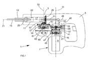
- Figure 1 is a sectional view of an embodiment of a pneumatic hammer according to the present invention.
- FIG. 1 A cross sectional view of an embodiment of a pneumatic hammer 1 according to the present invention is shown in Figure 1 .
- the hammer 1 comprises a housing 3 which is provided with a handle portion 5 at the rear end and motor housing portion 7 at the lower part.
- a drive train is arranged which comprises a drive motor 9 in the form of an electric motor and a hollow output spindle 11 rotatably supported in the housing 3.
- a tool holder 13 is fixedly mounted which is designed such that a tool bit 15 may be supported in the tool holder 13 in such a manner that it is rotationally fixed but may slide in the tool holder 13 in the axial direction of the output spindle 11 to an extent defined by the tool holder 15.
- a cylinder 17 is formed in which a piston 19 is slidably supported so that is may move along the longitudinal axis 21 of the output spindle 11.
- a ram 23 and a beat piece 25 are arranged inside the spindle 11 wherein an air cushion is formed between the piston 19 and the ram 23 so that when the piston 19 is reciprocatingly driven the ram 23 will reciprocate or move back and forth as well.
- the ram 23 during a back and forth movement slides towards the front it will hit the rear end of the beat piece 25 and an axial impact is imparted to the beat piece 25. This impact is then transferred to the tool bit 15 and on a workpiece (not shown).
- a conversion mechanism which converts the rotational movement of the armature 27 of the drive motor 9 into a reciprocating movement and which will be described in detail below.
- the general concept of such a hammer mechanism is well known in the prior art and does not require further explanation.
- the hollow spindle 11 is provided with a spindle bevel gear 29 which surrounds the spindle 11 so that the output spindle 11 may rotationally be driven by the drive motor 9, and the coupling between the drive motor 9 and spindle bevel gear 29 will be described in detail below.
- the drive motor 9 is arranged in the housing 3 in such a manner that the armature 27 extends along first axis 31 which is perpendicular to the axis 21 along which the output spindle 11 extends.
- the drive motor 9 is coupled to the piston 19 and the spindle bevel gear 29 so as to effect a reciprocating movement and rotation, respectively, by the arrangement as described in the following.
- a rotatable input member in the form of a first carrier 33 is rotatably mounted with respect to this axis inside the housing 3.
- the first carrier 33 eccentrically rotatably supports first planet gears 35.
- a first sun gear 37 is coaxially arranged with the first carrier 33 and meshingly engages with the first planet gears 35.
- a first ring gear 39 is coaxially arranged with the first axis of rotation 31, is movable parallel to the first axis 31 between a first position and a second position as indicated by the arrow 40. Both in the first and second positions the first ring gear 39 meshingly engages with the first planet gears 35.
- means are provided which are not shown in detail and which are adapted to selectively lock or to allow rotation of the first ring gear 39 with respect to the housing 3 when the first ring gear 39 is in the first position or in the second position.
- means are provided that may lock the first carrier 33 with respect to the housing 3.
- the first sun gear 37 is formed on a carrier 41 which is rotatably supported in the housing with respect to the first axis 31, wherein the carrier 41 on the side remote from the first carrier 33 and opposite the first sun gear 37 supports eccentrically with respect to the first axis 31 rotatable planet gears 43.
- a further sun gear 45 is coaxially arranged with the first axis 31 and meshingly engages with the third planet gears 43 supported on the carrier 41.
- the sun gear 45 is coupled to the armature 27 of the drive motor 9, i.e. it is integrally formed therewith.
- a further ring gear 47 is coaxially arranged with the first axis 31 and meshingly engages with the planet gears 43, this ring gear 47 being rotationally fixed with respect to the housing 3.
- an eccentric pin 49 is provided on the first carrier 33 opposite to the first planet gears 35 wherein a connecting rod 51 connects the eccentric pin 49 with the rear end of the piston 19 and forms an output member.
- the spindle bevel gear 29 meshingly engages with a drive member formed as a bevel gear 53 which is rotatably supported in the housing with respect to second axis 55, the second axis 55 being parallel to and at a distance from the first axis 31.
- a drive member formed as a bevel gear 53 which is rotatably supported in the housing with respect to second axis 55, the second axis 55 being parallel to and at a distance from the first axis 31.
- a second gear 57 Formed in one piece with the bevel gear 53 is a second gear 57 having an outer toothing.
- the first ring gear 39 is provided with an outer toothing as well and when the first ring gear 39 is in the second position (not shown in Figure 1 ) the outer toothings of the first ring gear 39 and the second gear 57 meshingly engage, whereas the first ring gear 39 and the second gear 57 are disengaged when the first ring gear 39 is in the first position (see Figure 1 ).
- a coupling section which connects the second gear 57 and the drive motor 9 via a releasable connection which has an open state in which the second gear 57 is not rotatingly driven by the drive motor 9, and a closed state in which the second gear 57 is rotatingly driven by the drive motor 9.
- the coupling section comprises a second carrier 59 formed on the second gear 57 and rotatably supporting second planet gears 61, which are eccentrically arranged with respect to the second axis 55.
- a second sun gear 63 is coaxially arranged with the second axis 55 and meshingly engages with the second planet gears 61.
- a second ring gear 65 is coaxially arranged with respect to the second axis 55 and meshingly engages with the second planet gears 61.
- a first gear element 67 is formed as an outer toothing.
- the second sun gear 63 is integrally formed with a second gear element 69 positioned on the side remote from the second carrier 59, wherein the first and the second gear elements 67, 69 may meshingly engage.
- the first gear element 67 is in meshing engagement with the second gear element 69 (not shown) whereas in the open state of the connection the first gear element and the second gear element are disengaged.
- the second gear element 69 together with the second sun gear 63 is movable along the second axis 55 between a first position, in which the second gear element 69 meshingly engages with the first gear element 67, and a second position in which the first and second gear elements 67, 69 are disengaged (see Figure 1 ).
- the releasable connection is formed by the axially movable combination of the second sun gear 63 and the second gear element 69.
- the second ring gear 65 is releasably supported in the housing 3 so that it may rotate, and in the closed state of the connection the second ring gear 65 is locked with respect to the housing 3, whereas in the open state of the connection the second ring gear 65 is freely rotatable with respect to the housing 3.
- a mode change mechanism which is not shown in the figures is adapted
- the mode change mechanism when the mode change mechanism is set to the fourth setting (reverse rotation mode) it shifts the first ring gear 39 to the second position but allows for a rotation of the first ring gear 39 with respect to the tool housing 3.
- the releasable connection coupling the second gear 57 with the drive motor is moved to the open state, i.e. the combination of the second gear element 69 and the second sun gear 63 is shifted such that the first and second gear elements 67, 69 do not engage.
- first ring gear 39 torque may be transmitted to the output spindle 11 via the first sun gear 37 and the first planet gears 35 while the first carrier 33 is preferably prevented from rotation by the means that lock the first carrier 33 with respect to the housing when the mode change mechanism is in the fourth setting.
- an additional path is provided for transferring torque from the drive motor 9 to the second gear 57 which path is configured such that the rotational direction with which the output spindle 11 rotates when being driven through this additional path is different from the rotational direction of the output spindle 11 when driven via the releasable connection even though in either case the rotational direction of the armature 27 of drive motor 9 is the same.
- an element of the planetary gear set which is connected to the conversion mechanism can be used to transfer torque to the output spindle 11 and to drive it in reverse direction.
- Reverse rotation of the output spindle 11 can be achieved without reversing the rotational direction of the armature 27 and without a complicated mechanical assembly added to the drive train. Instead simply the first ring gear 39 in the torque path to the conversion mechanism for the hammer mechanism needs to be adapted to assume first and second positions. At the same time a simple option is provided to prevent the output spindle 11 from rotation when the hammer is in chisel mode.
Landscapes
- Engineering & Computer Science (AREA)
- Mechanical Engineering (AREA)
- Drilling And Boring (AREA)
- Percussive Tools And Related Accessories (AREA)
Applications Claiming Priority (1)
| Application Number | Priority Date | Filing Date | Title |
|---|---|---|---|
| GB1418561.5A GB2531995A (en) | 2014-10-20 | 2014-10-20 | Pneumatic hammer |
Publications (2)
| Publication Number | Publication Date |
|---|---|
| EP3012071A1 true EP3012071A1 (de) | 2016-04-27 |
| EP3012071B1 EP3012071B1 (de) | 2017-03-22 |
Family
ID=52013243
Family Applications (1)
| Application Number | Title | Priority Date | Filing Date |
|---|---|---|---|
| EP15190218.6A Active EP3012071B1 (de) | 2014-10-20 | 2015-10-16 | Drucklufthammer |
Country Status (3)
| Country | Link |
|---|---|
| US (1) | US10099359B2 (de) |
| EP (1) | EP3012071B1 (de) |
| GB (1) | GB2531995A (de) |
Families Citing this family (11)
| Publication number | Priority date | Publication date | Assignee | Title |
|---|---|---|---|---|
| DE102014222253A1 (de) * | 2014-10-31 | 2016-05-04 | Robert Bosch Gmbh | Handwerkzeugmaschinenvorrichtung |
| WO2019079560A1 (en) | 2017-10-20 | 2019-04-25 | Milwaukee Electric Tool Corporation | PERCUSSION TOOL |
| US11059155B2 (en) | 2018-01-26 | 2021-07-13 | Milwaukee Electric Tool Corporation | Percussion tool |
| EP3856463B1 (de) | 2018-09-24 | 2024-09-11 | Milwaukee Electric Tool Corporation | Verfahren und werkzeugmaschine mit einer eingangssteuervorrichtung am gehäuseoberteil |
| CN216127155U (zh) * | 2019-04-10 | 2022-03-25 | 米沃奇电动工具公司 | 冲击工具 |
| EP3782766A1 (de) * | 2019-08-19 | 2021-02-24 | Hilti Aktiengesellschaft | Handwerkzeugmaschine |
| EP3854532A1 (de) * | 2019-08-19 | 2021-07-28 | Hilti Aktiengesellschaft | Handwerkzeugmaschine, werkzeug und handwerkzeugmaschinensystem mit bestimmtem drehzahl-schlagleistungs-verhältnis |
| EP3789161A1 (de) * | 2019-09-06 | 2021-03-10 | Hilti Aktiengesellschaft | Handwerkzeugmaschine |
| CN112247915A (zh) * | 2020-11-11 | 2021-01-22 | 江苏铁锚工具有限公司 | 双马达交直流无刷电锤 |
| WO2022216964A1 (en) * | 2021-04-07 | 2022-10-13 | Milwaukee Electric Tool Corporation | Impact power tool |
| US20250242483A1 (en) * | 2024-01-25 | 2025-07-31 | Milwaukee Electric Tool Corporation | Reciprocating impact tool with motor control |
Citations (5)
| Publication number | Priority date | Publication date | Assignee | Title |
|---|---|---|---|---|
| JPH10180513A (ja) * | 1996-12-13 | 1998-07-07 | Robert Bosch Gmbh | 手持ち式工作機械用の多段伝動装置 |
| US20050224242A1 (en) * | 2004-04-08 | 2005-10-13 | Rory Britz | Hammer drill |
| DE102004055236A1 (de) * | 2004-11-16 | 2006-05-18 | Robert Bosch Gmbh | Handwerkzeugmaschine mit wählbaren Betriebarten |
| DE102010062104A1 (de) * | 2010-11-29 | 2012-05-31 | Robert Bosch Gmbh | Hammerschlagwerk |
| US20120186842A1 (en) * | 2009-09-01 | 2012-07-26 | Robert Bosch Gmbh | Drill hammer and/or chipping hammer device |
Family Cites Families (4)
| Publication number | Priority date | Publication date | Assignee | Title |
|---|---|---|---|---|
| US4346769A (en) * | 1978-12-12 | 1982-08-31 | Black & Decker Inc. | Percussive tool drive linkage |
| DE3538166A1 (de) * | 1985-10-26 | 1987-04-30 | Hilti Ag | Bohrhammer mit dreharretierung |
| US7306048B2 (en) * | 2004-11-24 | 2007-12-11 | Hitachi Koki Co., Ltd. | Hammer drill having switching mechanism for switching operation modes |
| DE102013212753A1 (de) * | 2013-06-28 | 2014-12-31 | Robert Bosch Gmbh | Schlagwerksvorrichtung |
-
2014
- 2014-10-20 GB GB1418561.5A patent/GB2531995A/en not_active Withdrawn
-
2015
- 2015-10-16 EP EP15190218.6A patent/EP3012071B1/de active Active
- 2015-10-16 US US14/884,906 patent/US10099359B2/en active Active
Patent Citations (5)
| Publication number | Priority date | Publication date | Assignee | Title |
|---|---|---|---|---|
| JPH10180513A (ja) * | 1996-12-13 | 1998-07-07 | Robert Bosch Gmbh | 手持ち式工作機械用の多段伝動装置 |
| US20050224242A1 (en) * | 2004-04-08 | 2005-10-13 | Rory Britz | Hammer drill |
| DE102004055236A1 (de) * | 2004-11-16 | 2006-05-18 | Robert Bosch Gmbh | Handwerkzeugmaschine mit wählbaren Betriebarten |
| US20120186842A1 (en) * | 2009-09-01 | 2012-07-26 | Robert Bosch Gmbh | Drill hammer and/or chipping hammer device |
| DE102010062104A1 (de) * | 2010-11-29 | 2012-05-31 | Robert Bosch Gmbh | Hammerschlagwerk |
Also Published As
| Publication number | Publication date |
|---|---|
| EP3012071B1 (de) | 2017-03-22 |
| GB2531995A (en) | 2016-05-11 |
| GB201418561D0 (en) | 2014-12-03 |
| US10099359B2 (en) | 2018-10-16 |
| US20160107303A1 (en) | 2016-04-21 |
Similar Documents
| Publication | Publication Date | Title |
|---|---|---|
| EP3012071B1 (de) | Drucklufthammer | |
| EP1690642B1 (de) | Handgehaltene Schlagmaschine | |
| US20090308626A1 (en) | Electric hand tool | |
| JP4673118B2 (ja) | ハンマドリル装置 | |
| CN101541480B (zh) | 手持式工具机 | |
| CN111315538B (zh) | 手持式工具机器 | |
| CN102189284A (zh) | 锤钻装置 | |
| JP2003236769A (ja) | 手工具装置の作動モード切替ユニット | |
| US10315298B2 (en) | Impact mechanism device | |
| JP4446248B2 (ja) | ハンマドリル | |
| US9873192B2 (en) | Rotary hammer | |
| US20100270045A1 (en) | Handheld power tool | |
| EP3603892B1 (de) | Bohrhammer | |
| US20220288759A1 (en) | Hand-held power tool | |
| EP2883661B1 (de) | Bohrhammer | |
| US11969867B2 (en) | Hand-held power tool | |
| CN101100006A (zh) | 锤钻和/或冲击锤 | |
| CN112757231B (zh) | 锤钻 | |
| CN101568409A (zh) | 手持式工具机 | |
| JP2013091117A (ja) | 打撃工具 | |
| GB2439186A (en) | Hammer drill with bevel gear transmission | |
| JP2006289576A (ja) | ハンマドリル |
Legal Events
| Date | Code | Title | Description |
|---|---|---|---|
| PUAI | Public reference made under article 153(3) epc to a published international application that has entered the european phase |
Free format text: ORIGINAL CODE: 0009012 |
|
| 17P | Request for examination filed |
Effective date: 20160322 |
|
| AK | Designated contracting states |
Kind code of ref document: A1 Designated state(s): AL AT BE BG CH CY CZ DE DK EE ES FI FR GB GR HR HU IE IS IT LI LT LU LV MC MK MT NL NO PL PT RO RS SE SI SK SM TR |
|
| AX | Request for extension of the european patent |
Extension state: BA ME |
|
| GRAP | Despatch of communication of intention to grant a patent |
Free format text: ORIGINAL CODE: EPIDOSNIGR1 |
|
| STAA | Information on the status of an ep patent application or granted ep patent |
Free format text: STATUS: GRANT OF PATENT IS INTENDED |
|
| RIC1 | Information provided on ipc code assigned before grant |
Ipc: B25D 16/00 20060101AFI20161219BHEP Ipc: B25F 5/00 20060101ALI20161219BHEP |
|
| GRAS | Grant fee paid |
Free format text: ORIGINAL CODE: EPIDOSNIGR3 |
|
| INTG | Intention to grant announced |
Effective date: 20170120 |
|
| GRAA | (expected) grant |
Free format text: ORIGINAL CODE: 0009210 |
|
| STAA | Information on the status of an ep patent application or granted ep patent |
Free format text: STATUS: THE PATENT HAS BEEN GRANTED |
|
| AK | Designated contracting states |
Kind code of ref document: B1 Designated state(s): AL AT BE BG CH CY CZ DE DK EE ES FI FR GB GR HR HU IE IS IT LI LT LU LV MC MK MT NL NO PL PT RO RS SE SI SK SM TR |
|
| REG | Reference to a national code |
Ref country code: GB Ref legal event code: FG4D |
|
| REG | Reference to a national code |
Ref country code: CH Ref legal event code: EP |
|
| REG | Reference to a national code |
Ref country code: AT Ref legal event code: REF Ref document number: 877250 Country of ref document: AT Kind code of ref document: T Effective date: 20170415 |
|
| REG | Reference to a national code |
Ref country code: IE Ref legal event code: FG4D |
|
| REG | Reference to a national code |
Ref country code: DE Ref legal event code: R096 Ref document number: 602015001940 Country of ref document: DE |
|
| REG | Reference to a national code |
Ref country code: NL Ref legal event code: MP Effective date: 20170322 |
|
| PG25 | Lapsed in a contracting state [announced via postgrant information from national office to epo] |
Ref country code: FI Free format text: LAPSE BECAUSE OF FAILURE TO SUBMIT A TRANSLATION OF THE DESCRIPTION OR TO PAY THE FEE WITHIN THE PRESCRIBED TIME-LIMIT Effective date: 20170322 Ref country code: LT Free format text: LAPSE BECAUSE OF FAILURE TO SUBMIT A TRANSLATION OF THE DESCRIPTION OR TO PAY THE FEE WITHIN THE PRESCRIBED TIME-LIMIT Effective date: 20170322 Ref country code: HR Free format text: LAPSE BECAUSE OF FAILURE TO SUBMIT A TRANSLATION OF THE DESCRIPTION OR TO PAY THE FEE WITHIN THE PRESCRIBED TIME-LIMIT Effective date: 20170322 Ref country code: NO Free format text: LAPSE BECAUSE OF FAILURE TO SUBMIT A TRANSLATION OF THE DESCRIPTION OR TO PAY THE FEE WITHIN THE PRESCRIBED TIME-LIMIT Effective date: 20170622 Ref country code: GR Free format text: LAPSE BECAUSE OF FAILURE TO SUBMIT A TRANSLATION OF THE DESCRIPTION OR TO PAY THE FEE WITHIN THE PRESCRIBED TIME-LIMIT Effective date: 20170623 |
|
| REG | Reference to a national code |
Ref country code: LT Ref legal event code: MG4D |
|
| REG | Reference to a national code |
Ref country code: AT Ref legal event code: MK05 Ref document number: 877250 Country of ref document: AT Kind code of ref document: T Effective date: 20170322 |
|
| PG25 | Lapsed in a contracting state [announced via postgrant information from national office to epo] |
Ref country code: LV Free format text: LAPSE BECAUSE OF FAILURE TO SUBMIT A TRANSLATION OF THE DESCRIPTION OR TO PAY THE FEE WITHIN THE PRESCRIBED TIME-LIMIT Effective date: 20170322 Ref country code: SE Free format text: LAPSE BECAUSE OF FAILURE TO SUBMIT A TRANSLATION OF THE DESCRIPTION OR TO PAY THE FEE WITHIN THE PRESCRIBED TIME-LIMIT Effective date: 20170322 Ref country code: RS Free format text: LAPSE BECAUSE OF FAILURE TO SUBMIT A TRANSLATION OF THE DESCRIPTION OR TO PAY THE FEE WITHIN THE PRESCRIBED TIME-LIMIT Effective date: 20170322 Ref country code: BG Free format text: LAPSE BECAUSE OF FAILURE TO SUBMIT A TRANSLATION OF THE DESCRIPTION OR TO PAY THE FEE WITHIN THE PRESCRIBED TIME-LIMIT Effective date: 20170622 |
|
| PG25 | Lapsed in a contracting state [announced via postgrant information from national office to epo] |
Ref country code: NL Free format text: LAPSE BECAUSE OF FAILURE TO SUBMIT A TRANSLATION OF THE DESCRIPTION OR TO PAY THE FEE WITHIN THE PRESCRIBED TIME-LIMIT Effective date: 20170322 |
|
| PG25 | Lapsed in a contracting state [announced via postgrant information from national office to epo] |
Ref country code: SK Free format text: LAPSE BECAUSE OF FAILURE TO SUBMIT A TRANSLATION OF THE DESCRIPTION OR TO PAY THE FEE WITHIN THE PRESCRIBED TIME-LIMIT Effective date: 20170322 Ref country code: IT Free format text: LAPSE BECAUSE OF FAILURE TO SUBMIT A TRANSLATION OF THE DESCRIPTION OR TO PAY THE FEE WITHIN THE PRESCRIBED TIME-LIMIT Effective date: 20170322 Ref country code: CZ Free format text: LAPSE BECAUSE OF FAILURE TO SUBMIT A TRANSLATION OF THE DESCRIPTION OR TO PAY THE FEE WITHIN THE PRESCRIBED TIME-LIMIT Effective date: 20170322 Ref country code: ES Free format text: LAPSE BECAUSE OF FAILURE TO SUBMIT A TRANSLATION OF THE DESCRIPTION OR TO PAY THE FEE WITHIN THE PRESCRIBED TIME-LIMIT Effective date: 20170322 Ref country code: AT Free format text: LAPSE BECAUSE OF FAILURE TO SUBMIT A TRANSLATION OF THE DESCRIPTION OR TO PAY THE FEE WITHIN THE PRESCRIBED TIME-LIMIT Effective date: 20170322 Ref country code: RO Free format text: LAPSE BECAUSE OF FAILURE TO SUBMIT A TRANSLATION OF THE DESCRIPTION OR TO PAY THE FEE WITHIN THE PRESCRIBED TIME-LIMIT Effective date: 20170322 Ref country code: EE Free format text: LAPSE BECAUSE OF FAILURE TO SUBMIT A TRANSLATION OF THE DESCRIPTION OR TO PAY THE FEE WITHIN THE PRESCRIBED TIME-LIMIT Effective date: 20170322 |
|
| PG25 | Lapsed in a contracting state [announced via postgrant information from national office to epo] |
Ref country code: IS Free format text: LAPSE BECAUSE OF FAILURE TO SUBMIT A TRANSLATION OF THE DESCRIPTION OR TO PAY THE FEE WITHIN THE PRESCRIBED TIME-LIMIT Effective date: 20170722 Ref country code: SM Free format text: LAPSE BECAUSE OF FAILURE TO SUBMIT A TRANSLATION OF THE DESCRIPTION OR TO PAY THE FEE WITHIN THE PRESCRIBED TIME-LIMIT Effective date: 20170322 Ref country code: PL Free format text: LAPSE BECAUSE OF FAILURE TO SUBMIT A TRANSLATION OF THE DESCRIPTION OR TO PAY THE FEE WITHIN THE PRESCRIBED TIME-LIMIT Effective date: 20170322 Ref country code: PT Free format text: LAPSE BECAUSE OF FAILURE TO SUBMIT A TRANSLATION OF THE DESCRIPTION OR TO PAY THE FEE WITHIN THE PRESCRIBED TIME-LIMIT Effective date: 20170724 |
|
| REG | Reference to a national code |
Ref country code: DE Ref legal event code: R097 Ref document number: 602015001940 Country of ref document: DE |
|
| PLBE | No opposition filed within time limit |
Free format text: ORIGINAL CODE: 0009261 |
|
| STAA | Information on the status of an ep patent application or granted ep patent |
Free format text: STATUS: NO OPPOSITION FILED WITHIN TIME LIMIT |
|
| PG25 | Lapsed in a contracting state [announced via postgrant information from national office to epo] |
Ref country code: DK Free format text: LAPSE BECAUSE OF FAILURE TO SUBMIT A TRANSLATION OF THE DESCRIPTION OR TO PAY THE FEE WITHIN THE PRESCRIBED TIME-LIMIT Effective date: 20170322 |
|
| 26N | No opposition filed |
Effective date: 20180102 |
|
| PG25 | Lapsed in a contracting state [announced via postgrant information from national office to epo] |
Ref country code: SI Free format text: LAPSE BECAUSE OF FAILURE TO SUBMIT A TRANSLATION OF THE DESCRIPTION OR TO PAY THE FEE WITHIN THE PRESCRIBED TIME-LIMIT Effective date: 20170322 |
|
| PG25 | Lapsed in a contracting state [announced via postgrant information from national office to epo] |
Ref country code: MC Free format text: LAPSE BECAUSE OF FAILURE TO SUBMIT A TRANSLATION OF THE DESCRIPTION OR TO PAY THE FEE WITHIN THE PRESCRIBED TIME-LIMIT Effective date: 20170322 |
|
| REG | Reference to a national code |
Ref country code: IE Ref legal event code: MM4A |
|
| REG | Reference to a national code |
Ref country code: FR Ref legal event code: ST Effective date: 20180629 |
|
| PG25 | Lapsed in a contracting state [announced via postgrant information from national office to epo] |
Ref country code: LU Free format text: LAPSE BECAUSE OF NON-PAYMENT OF DUE FEES Effective date: 20171016 |
|
| REG | Reference to a national code |
Ref country code: BE Ref legal event code: MM Effective date: 20171031 |
|
| PG25 | Lapsed in a contracting state [announced via postgrant information from national office to epo] |
Ref country code: BE Free format text: LAPSE BECAUSE OF NON-PAYMENT OF DUE FEES Effective date: 20171031 Ref country code: FR Free format text: LAPSE BECAUSE OF NON-PAYMENT OF DUE FEES Effective date: 20171031 |
|
| PG25 | Lapsed in a contracting state [announced via postgrant information from national office to epo] |
Ref country code: MT Free format text: LAPSE BECAUSE OF NON-PAYMENT OF DUE FEES Effective date: 20171016 |
|
| PG25 | Lapsed in a contracting state [announced via postgrant information from national office to epo] |
Ref country code: IE Free format text: LAPSE BECAUSE OF NON-PAYMENT OF DUE FEES Effective date: 20171016 |
|
| REG | Reference to a national code |
Ref country code: CH Ref legal event code: PL |
|
| PG25 | Lapsed in a contracting state [announced via postgrant information from national office to epo] |
Ref country code: HU Free format text: LAPSE BECAUSE OF FAILURE TO SUBMIT A TRANSLATION OF THE DESCRIPTION OR TO PAY THE FEE WITHIN THE PRESCRIBED TIME-LIMIT; INVALID AB INITIO Effective date: 20151016 |
|
| PG25 | Lapsed in a contracting state [announced via postgrant information from national office to epo] |
Ref country code: CH Free format text: LAPSE BECAUSE OF NON-PAYMENT OF DUE FEES Effective date: 20181031 Ref country code: LI Free format text: LAPSE BECAUSE OF NON-PAYMENT OF DUE FEES Effective date: 20181031 |
|
| PG25 | Lapsed in a contracting state [announced via postgrant information from national office to epo] |
Ref country code: CY Free format text: LAPSE BECAUSE OF FAILURE TO SUBMIT A TRANSLATION OF THE DESCRIPTION OR TO PAY THE FEE WITHIN THE PRESCRIBED TIME-LIMIT Effective date: 20170322 |
|
| PG25 | Lapsed in a contracting state [announced via postgrant information from national office to epo] |
Ref country code: MK Free format text: LAPSE BECAUSE OF FAILURE TO SUBMIT A TRANSLATION OF THE DESCRIPTION OR TO PAY THE FEE WITHIN THE PRESCRIBED TIME-LIMIT Effective date: 20170322 |
|
| PG25 | Lapsed in a contracting state [announced via postgrant information from national office to epo] |
Ref country code: TR Free format text: LAPSE BECAUSE OF FAILURE TO SUBMIT A TRANSLATION OF THE DESCRIPTION OR TO PAY THE FEE WITHIN THE PRESCRIBED TIME-LIMIT Effective date: 20170322 |
|
| PG25 | Lapsed in a contracting state [announced via postgrant information from national office to epo] |
Ref country code: AL Free format text: LAPSE BECAUSE OF FAILURE TO SUBMIT A TRANSLATION OF THE DESCRIPTION OR TO PAY THE FEE WITHIN THE PRESCRIBED TIME-LIMIT Effective date: 20170322 |
|
| PGFP | Annual fee paid to national office [announced via postgrant information from national office to epo] |
Ref country code: DE Payment date: 20251020 Year of fee payment: 11 |
|
| PGFP | Annual fee paid to national office [announced via postgrant information from national office to epo] |
Ref country code: GB Payment date: 20251024 Year of fee payment: 11 |