EP3856463B1 - Verfahren und werkzeugmaschine mit einer eingangssteuervorrichtung am gehäuseoberteil - Google Patents
Verfahren und werkzeugmaschine mit einer eingangssteuervorrichtung am gehäuseoberteil Download PDFInfo
- Publication number
- EP3856463B1 EP3856463B1 EP19866669.5A EP19866669A EP3856463B1 EP 3856463 B1 EP3856463 B1 EP 3856463B1 EP 19866669 A EP19866669 A EP 19866669A EP 3856463 B1 EP3856463 B1 EP 3856463B1
- Authority
- EP
- European Patent Office
- Prior art keywords
- mode
- power tool
- controller
- signal
- motor
- Prior art date
- Legal status (The legal status is an assumption and is not a legal conclusion. Google has not performed a legal analysis and makes no representation as to the accuracy of the status listed.)
- Active
Links
Images


Classifications
-
- B—PERFORMING OPERATIONS; TRANSPORTING
- B25—HAND TOOLS; PORTABLE POWER-DRIVEN TOOLS; MANIPULATORS
- B25F—COMBINATION OR MULTI-PURPOSE TOOLS NOT OTHERWISE PROVIDED FOR; DETAILS OR COMPONENTS OF PORTABLE POWER-DRIVEN TOOLS NOT PARTICULARLY RELATED TO THE OPERATIONS PERFORMED AND NOT OTHERWISE PROVIDED FOR
- B25F5/00—Details or components of portable power-driven tools not particularly related to the operations performed and not otherwise provided for
- B25F5/001—Gearings, speed selectors, clutches or the like specially adapted for rotary tools
-
- B—PERFORMING OPERATIONS; TRANSPORTING
- B25—HAND TOOLS; PORTABLE POWER-DRIVEN TOOLS; MANIPULATORS
- B25F—COMBINATION OR MULTI-PURPOSE TOOLS NOT OTHERWISE PROVIDED FOR; DETAILS OR COMPONENTS OF PORTABLE POWER-DRIVEN TOOLS NOT PARTICULARLY RELATED TO THE OPERATIONS PERFORMED AND NOT OTHERWISE PROVIDED FOR
- B25F5/00—Details or components of portable power-driven tools not particularly related to the operations performed and not otherwise provided for
- B25F5/02—Construction of casings, bodies or handles
Definitions
- the present disclosure relates to power tools. More specifically, the present disclosure relates to a power tool including an input control device on a top portion of a housing.
- a switch may be located near the trigger to change the operating mode of the power tool.
- the switch may have a forward positon, a reverse position, and a lock position.
- a user actuation of the trigger causes an output spindle of the power tool to operate in a forward direction.
- the switch is in the reverse position, a user actuation of the trigger causes an output spindle of the power tool to operate in a reverse direction.
- the switch is in the lock position, a user actuation of the trigger has no effect.
- the positioning of the switch near the trigger increases the size of the handle portion of the power tool and may lead to inadvertent changes to the switch position when the user engages the trigger.
- US2004140781 (CRAVEN DANIEL [GB], et al ) relates to an electric motor driven hand-held tool.
- an electric motor driven hand-held tool such as a drilling, hammering or screw driving tool having a tool housing within which is located an integrated switch unit.
- the switch unit includes an electronic motor control unit, a first actuator which is actuated by a manually operable power member and to which the control unit is responsive to power the motor and a second actuator which is actuated by a manually operable forward/reverse member and to which the control unit is responsive to drive the motor in a selected forward or reverse direction.
- the forward/reverse member is located remotely from the switch unit on a portion of the tool housing which can be seen by a user of the tool during normal operation of the tool.
- a linkage arrangement is provided for actuating the second actuator in response to a manual actuation of the forward/reverse member.
- the linkage is pivotally mounted on a closed end of a jam pot motor casing.
- the linkage comprises a central annular portion pivotally mounted on a boss formed on the motor housing, a first upwardly extending arm on which the forward/reverse lever is formed and a second downwardly extending arm which engages the second actuator.
- an electric-motor-driven hand-held apparatus has a changeover switch for the rotation direction of the motor, in addition to a mains switch.
- the changeover switch is physically separated from the mains switch.
- a blocking device in the form of a displaceable bolt, which prevents operation of the changeover switch when the mains switch is operated.
- DE102012220423 (BOSCH GMBH ROBERT [DE] ) relates to a hand tool machine i.e. cordless screwdriver, has pistol-shaped machine housing including main handle, and operating element attached to side of machine housing, where side of machine housing turns away toward main handle.
- the machine has an operating unit that switches between left hand motion and right hand motion by movement of an operating element of the operating unit parallel to a tool rotational axis.
- the operating unit includes a protective unit, which is intended to prevent switching between the left and right hand motions during activation of a drive unit.
- Pistol-shaped machine housing includes a main handle.
- the operating element is attached to a side of the housing, where the side of the housing turns away toward the handle.
- US5014793 (GERMANTON DAMON [US], et al ) relates to a variable speed DC motor controller apparatus particularly adapted for control of portable-power tools.
- a portable electric power tool having a DC motor for driving tool bit is controlled according to speed and torque by employing a zero displacement switch means which is coupled to the tool and operative to provide an output voltage proportional to the pressure applied to the switch means via the hand of the user.
- the zero displacement switch interfaces with a piezoresistive array which produces a voltage output proportional to the pressure applied to the zero displacement switch.
- the voltage output of the array is applied to control circuit means which are coupled to the motor and which controls the speed of the motor according to the pressure applied to the switch.
- motor control circuitry which operates to monitor the current through the DC motor to control the speed of the motor according to the torque imparted upon the tool bit being accommodated by the portable electric tool.
- a power tool including the features of claim 1.
- a method for changing an operational mode of a power tool including the features of claim 6.
- the input control device is further configured to receive a plurality of actuations, and to generate the mode signal responsive to each of the plurality of actuations. Additionally, the controller is further configured to receive the mode signal from the input control device upon each actuation of the input control device, and to sequentially switch among each of the plurality of operational modes responsive to each mode signal received from the input control device.
- a trigger is positioned on the handle portion of the housing on a side of the motor housing portion opposite the input control device.
- the controller is configured to receive a trigger signal responsive to an actuation of the trigger and operate the motor according to the selected one of the plurality of operational modes and the trigger signal.
- an output spindle extends from the motor housing portion, and the controller is configured to receive a trigger signal responsive to an actuation of the trigger and operate the motor to control a rotation direction of the output spindle based on the trigger signal and the selected one of the plurality of operational modes.
- embodiments may include hardware, software, and electronic components or modules that, for purposes of discussion, may be illustrated and described as if the majority of the components were implemented solely in hardware.
- the electronic-based aspects may be implemented in software (e.g., stored on non-transitory computer-readable medium) executable by one or more processing units, such as a microprocessor and/or application specific integrated circuits ("ASICs").
- ASICs application specific integrated circuits
- a plurality of hardware and software based devices, as well as a plurality of different structural components may be utilized to implement the embodiments.
- “servers” and “computing devices” described in the specification can include one or more processing units, one or more computer-readable medium modules, one or more input/output interfaces, and various connections (e.g., a system bus) connecting the components.
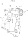
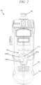
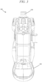
- FIGS. 1-5 illustrate a power tool 100 that includes a housing 105.
- the housing 105 includes a handle portion 110, a motor housing portion 112, and an input control device 115.
- the motor housing portion 112 houses a motor therein.
- the handle portion 110 extends away from the motor housing portion 112.
- the input control device 115 is, for example, a button or a switch that is configured to control an operational mode of the power tool 100.
- the input control device 115 is located on a top portion 120 of the housing 105. More particularly, as illustrated, the input control device 115 is positioned on a top portion of the motor housing portion 112, away from the handle portion 110.
- the illustrated input control device 115 is on a (top) side of the motor housing portion 112 opposite from a (bottom) side of the motor housing portion from which the handle portion 110 extends.
- the input control device 115 is located above the handle portion 110, a motor of the power tool 100, a trigger 125 of the power tool 100, an output spindle 130 of the power tool 100, a battery pack for powering the power tool 100, etc.
- the handle portion 110 can be made more compact.
- a physical lever typically located near a trigger for a power tool can be removed to make the handle portion 110 of the power tool 100 more compact.
- the input control device 115 which may also be referred to as a mode selector, generates a mode signal when actuated by a user of the power tool 100.
- the input control device 115 includes an electro-mechanical push button that generates a pulse in response to each actuation (e.g., depression).
- the button may be spring biased such that actuation momentarily depresses the button in a direction of the housing 105 (overcoming the biasing force of the spring) and then the biasing spring returns the button to an extended position when actuation is completed.
- the input control device 115 includes a touch switch, such as a capacitance switch.
- the generated mode signal is configured to control an operational mode of the power tool 100.
- the input control device 115 is configured to modify the operational mode of the power tool 100 among a motor forward mode of operation, a motor reverse mode of operation, and a locked tool mode of operation.
- FIG. 6 illustrates a simplified block diagram of the power tool 100, which includes a controller 200 and a power source 202.
- the power source 202 provides DC power to the various components of the power tool 100 and may be a power tool battery pack that is rechargeable and uses, for instance, lithium ion cell technology.
- the power source 202 may receive AC power (e.g., 120V/60Hz) from a tool plug that is coupled to a standard wall outlet, and then filter, condition, and rectify the received power to output DC power.
- AC power e.g., 120V/60Hz
- the controller 200 is electrically and/or communicatively connected to a variety of modules or components of the power tool 100.
- the illustrated controller 200 is connected to one or more indicators 205, a power input module 210, a battery pack interface 215, one or more sensors 220, a user input module 225, a trigger switch 230 (connected to a trigger 235), and a FET switching bridge 240 (e.g., including one or more switching FETs).
- the controller 200 includes combinations of hardware and software that are operable to, among other things, control the operation of the power tool 100, activate the one or more indicators 205 (e.g., a light emitting diode (LED)), monitor the operation of the power tool 100, etc.
- LED light emitting diode
- the controller 200 includes a plurality of electrical and electronic components that provide power, operational control, and protection to the components and modules within the controller 200 and/or the power tool 100.
- the controller 200 includes, among other things, a processing unit 250 (e.g., a microprocessor, a microcontroller, or another suitable programmable device), a memory 255, input units 260, and output units 265.
- the processing unit 250 includes, among other things, a control unit 270, an arithmetic logic unit (“ALU") 275, and a plurality of registers 280 (shown as a group of registers in FIG. 6 ), and is implemented using a known computer architecture (e.g., a modified Harvard architecture, a von Neumann architecture, etc.).
- the processing unit 250, the memory 255, the input units 260, and the output units 265 as well as the various modules connected to the controller 200 are connected by one or more control and/or data buses (e.g., common bus 285).
- the memory 255 is a non-transitory computer readable medium that includes, for example, a program storage area and a data storage area.
- the program storage area and the data storage area can include combinations of different types of memory, such as read-only memory (“ROM”), random access memory (“RAM”) (e.g., dynamic RAM ["DRAM”], synchronous DRAM ["SDRAM”], etc.), electrically erasable programmable read-only memory (“EEPROM”), flash memory, a hard disk, an SD card, or other suitable magnetic, optical, physical, or electronic memory devices.
- ROM read-only memory
- RAM random access memory
- EEPROM electrically erasable programmable read-only memory
- flash memory e.g., a hard disk, an SD card, or other suitable magnetic, optical, physical, or electronic memory devices.
- the processing unit 250 is connected to the memory 255 and executes software instructions that are capable of being stored in a RAM of the memory 255 (e.g., during execution), a ROM of the memory 255 (e.g., on a generally permanent basis), or another non-transitory computer readable medium such as another memory or a disc.
- Software included in the implementation of the power tool 100 can be stored in the memory 255 of the controller 200.
- the controller 200 is configured to retrieve from memory and execute, among other things, instructions related to the control of the power tool described herein.
- the indicators 205 include, for example, one or more light-emitting diodes ("LED").
- the sensors 220 include, for example, one or more current sensors, one or more speed sensors, one or more Hall Effect sensors, one or more temperature sensors, etc.
- the battery pack interface 215 includes a combination of mechanical and electrical components configured to, and operable for, interfacing (e.g., mechanically, electrically, and communicatively connecting) the power tool 100 with the power source 202.
- power provided by a battery pack an example of the power source 202
- the power input module 210 includes combinations of active and passive components to regulate or control the power received from the battery pack prior to power being provided to the controller 200.
- the battery pack interface 215 also supplies power to the FET switching bridge 240 to be switched by the switching FETs to selectively provide power to a motor 245.
- the motor 245 is housed within the motor housing portion 112 and is configured to drive the output spindle 130, either via a direct drive coupling or a transmission (e.g., including planetary gears).
- the battery pack interface 215 also includes, for example, a communication line 290 for providing a communication line or link between the controller 200 and a battery pack.
- the tool includes Hall sensors 246 (for example, three Hall sensors) mounted on a printed circuit board (not shown) positioned axially adjacent to the motor 245 at different radial positions (e.g., 120 degrees apart from one another).
- the Hall sensors 246 output motor feedback information, such as an indication (e.g., a pulse) each time a magnet of the rotor rotates across a face of one of the Hall sensors 246.
- the controller 200 can determine the position, velocity, and acceleration of the rotor.
- the controller 200 also receives user controls from user input 225 and the trigger switch 230. In response to the motor feedback information and user controls, the controller 200 transmits control signals to the FET switching bridge 240 to drive the motor 245.
- the power tool 100 may be a sensorless power tool that does not include a Hall sensor 246 or other position sensor to detect the position of the rotor. Rather, the rotor position may be detected based on the inductance of the motor 245 or the back emf generated in the motor 245.
- the controller 200 and other components of the power tool 100 are electrically coupled to the power source 202 such that the power source 202 provides power thereto.
- the FET switching bridge 240 includes a switch bridge having a plurality of high side power switching elements (for example, field effect transistors (FETs)) and a plurality of low side power switching elements (for example, FETs).
- the controller 200 provides the control signals to control the high side FETs and the low side FETs to drive the motor based on the motor feedback information and user controls, as noted above.
- the controller 200 in response to detecting a pull of the trigger 235 and the input from the user input module 225, the controller 200 provides the control signals to selectively enable and disable the FETs (e.g., sequentially, in pairs) resulting in power from the power source 202 to be selectively applied to stator coils of the motor 126 to cause rotation of a rotor. More particularly, to drive the motor 245, the controller 200 enables a first high side FET and first low side FET pair (e.g., by providing a voltage at a gate terminal of the FETs) for a first period of time.
- a first high side FET and first low side FET pair e.g., by providing a voltage at a gate terminal of the FETs
- the controller 200 In response to determining that the rotor of the motor 245 has rotated based on a pulse from the Hall sensors 246, the controller 200 disables the first FET pair, and enables a second high side FET and a second low side FET. In response to determining that the rotor of the motor 126 has rotated based on pulse(s) from the Hall sensors 246, the controller 200 disables the second FET pair, and enables a third high side FET and a third low side FET. In response to determining that the rotor of the motor 245 has rotated based on further pulse(s) from the Hall sensors 246, the controller 200 disables the third FET pair and returns to enable the first high side FET and the first low side FET.
- control signals include pulse width modulated (PWM) signals having a duty cycle that is set in proportion to the amount of trigger pull of the trigger 235, to thereby control the speed or torque of the motor 245.
- PWM pulse width modulated
- the sequence of cyclically enabling pairs of the high side FETs and the low side FETs proceeds in a first order (e.g., pair 1, pair 2, pair 3, pair 1, pair 2, etc.), and to drive the motor in a second direction (e.g., reverse), the sequence of cyclically enabling pairs of the high side FETs and the low side FETs proceeds in a second order (e.g., pair 3, pair 2, pair 1, pair 3, pair 2, etc.).
- the user input module 225 is operably coupled to the controller 200 to select a forward mode of operation, a reverse mode of operation, or a power tool lock mode of operation for the power tool 100.
- the user input module 225 includes the input control device 115 located on the top portion of the housing 105. Each time the input control device 115 is actuated by a user of the power tool 100, the controller 200 receives a mode signal from the use input module 225. Each time the controller 200 receives that mode signal from the user input module 225, the power tool 100 mode of operation is changed. The controller 200 sequentially switches among each of the forward mode of operation, the reverse mode of operation, and the power tool lock mode of operation.
- the power tool 100 includes a first mode of operation, a second mode of operation, and a third mode of operation. If the power tool 100 is currently operating in the first mode of operation, a mode signal from the user input module 225 will cause the controller 200 to switch to the second mode of operation. If the power tool 100 is currently operating in the second mode of operation, a mode signal from the user input module 225 will cause the controller 200 to switch to the third mode of operation. If the power tool 100 is currently operating in the third mode of operation, a mode signal from the user input module 225 will cause the controller 200 to switch to the first mode of operation.
- the first mode of operation is the forward mode of operation in which the controller 200 controls the FET switching bridge 240 to drive the motor 245 in a first (forward) direction in response to depression of the trigger 235 and the generation of a trigger signal.
- the second mode of operation is the reverse mode of operation in which the controller 200 controls the FET switching bridge 240 to drive the motor 245 in a second (reverse) direction, which is opposite the first (forward) direction, in response to depression of the trigger 235.
- the third mode of operation is the lock mode of operation in which the controller 200 prevents or suppresses driving of the motor 245 (e.g., by sending control signals to the FET switching bridge 240 or by not sending control signals to the FET switching bridge 240), even when the trigger signal is generated responsive to the trigger 235 being depressed.
- the controller 200 ignores user depression of the trigger 235 and does not drive the motor 245 in response to user depression of the trigger 235.
- the indicators 205 include LEDs to provide an indication of the mode of the power tool 100 as selected by the input control device 115.
- an LED of the indicators 205 may be associated with each symbol (i.e., forward arrow symbol 205A, reverse arrow symbol 205B, and lock symbol 205C) shown on the input control device 115.
- the controller 200 illuminates the LED associated with the current mode of operation of the power tool 100 (e.g., the forward arrow 205A is illuminated when in the forward mode of operation, the reverse arrow 205B is illuminating when in the reverse mode of operation, and the lock symbol 205C is illuminated when in the lock mode of operation).
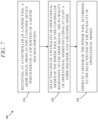
- FIG. 7 is a flow diagram of a method 300 of controlling an operating mode of a power tool. The method 300 is described with reference to the power tool 100 described above.
- a mode signal is received in a controller 200 of the power tool 100 from an input control device 115 positioned on a top portion 120 of a housing 105 of the power tool 100 positioned above a handle portion 110 of the housing 105.
- the mode signal is a pulse signal.
- the controller 200 selects a different one of a plurality of operational modes of the power tool 100 responsive to the mode signal.
- the operational modes include at least a forward mode and a reverse mode.
- the operational modes also include a lock mode of operation.
- the controller 200 may change a current operational mode of the tool (selected from the plurality of operational modes) to another operational mode (selected from the plurality of operational modes).
- the controller 200 operates the motor 245 according to the selected operational mode. For example, in the forward mode of operation, the controller 200 controls the FET switching bridge 240 to drive the motor 245 in a forward direction in response to a depression of the trigger 235 and the generation of a trigger signal by the trigger switch 230. In the reverse mode of operation, the controller 200 controls the FET switching bridge 240 to drive the motor 245 in a reverse direction, which is opposite the forward direction, in response to a depression of the trigger 235 and the generation of a trigger signal by the trigger switch 230.
- the controller 200 prevents or suppresses driving of the motor 245 by not sending control signals to the FET switching bridge 240 even when the trigger signal is generated responsive to the trigger 235 being depressed. In other words, in the lock mode of operation, the controller 200 ignores user depression of the trigger 235 and does not drive the motor 245 in response to user depression of the trigger 235.
- Operation of the power tool 100 according to the method 300 of FIG. 7 may continue after the tool is operated in block 330 by remaining in block 330 for subsequent actuations of the trigger 235 in the current operational mode, or by looping back to block 310 responsive to another actuation of the input control device 115 and generation of the mode signal.
- block 330 is bypassed when the input control device 115 is actuated a subsequent time before the trigger 235 is actuated.
- the controller 200 sequentially switches (i.e., cycles) through the operational modes each time an instance of the mode signal is received, and need not first operate the motor according to a selected mode before cycling to a next operational mode.
- the controller 200 may cycle the operational mode from forward, to reverse, to lock, back to forward, to reverse, to lock, and so forth.
- a different order of operational modes is used when cycling (e.g., forward, lock, reverse, forward, lock, reverse, and so forth).
- a power tool including an input control device located on a top portion of a housing for changing an operational mode of the power tool.
Landscapes
- Engineering & Computer Science (AREA)
- Mechanical Engineering (AREA)
- Portable Power Tools In General (AREA)
Claims (9)
- Elektrowerkzeug (100), umfassend:ein Gehäuse (105), das einen Griffabschnitt (110) und einen Motorgehäuseabschnitt (112) aufweist;einen Motor innerhalb des Motorgehäuseabschnitts;einen Moduswähler (115), der sich von dem Griffabschnitt entfernt befindet und konfiguriert ist, um ein Modussignal als Reaktion auf jede Betätigung des Moduswählers zu erzeugen;eine erste Anzeige (205) auf dem oberen Abschnitt des Motorgehäuseabschnitts;eine zweite Anzeige (205) auf dem oberen Abschnitt des Motorgehäuseabschnitts;eine dritte Anzeige (205) auf dem oberen Abschnitt des Motorgehäuseabschnitts; undeine Steuerung (200), die einen elektronischen Prozessor (250) und einen Speicher (255) einschließt, dadurch gekennzeichnet, dass sich der Moduswähler (115) an einem oberen Abschnitt (120) des Motorgehäuseabschnitts (112) befindet und der Speicher (255) Anweisungen speichert, die, wenn sie durch den elektronischen Prozessor ausgeführt werden, die Steuerung konfigurieren zum:Empfangen des Modussignals,sequentiellen Wechseln zu einem nächsten Betriebsmodus einer Vielzahl von Betriebsmodi des Elektrowerkzeugs, als Reaktion auf das Empfangen des Modussignals, um einen der Vielzahl von Betriebsmodi auszuwählen, wobei die Vielzahl von Betriebsmodi mindestens einen Vorwärtsmodus, einen Rückwärtsmodus und einen Sperrmodus des Elektrowerkzeugs einschließt, undBetreiben des Motors gemäß dem ausgewählten einen der Vielzahl von Betriebsmodi,Beleuchten der ersten Anzeige nach Empfangen eines ersten Modussignals von dem Moduswähler, um eine Auswahl eines ersten des Vorwärtsmodus, des Rückwärtsmodus und des Sperrmodus des Elektrowerkzeugs anzuzeigen,Beleuchten der zweiten Anzeige nach Empfangen eines zweiten Modussignals von dem Moduswähler, um eine Auswahl eines zweiten des Vorwärtsmodus, des Rückwärtsmodus und des Sperrmodus des Elektrowerkzeugs anzuzeigen, wobei das zweite Modussignal nach dem ersten Modussignal empfangen wird, undBeleuchten der dritten Anzeige nach Empfangen eines dritten Modussignals von dem Moduswähler, um eine Auswahl eines dritten des Vorwärtsmodus, des Rückwärtsmodus und des Sperrmodus des Elektrowerkzeugs anzuzeigen, wobei das dritte Modussignal nach dem zweiten Modussignal empfangen wird, undBeleuchten der ersten Anzeige nach Empfangen eines vierten Modussignals von dem Moduswähler, um die Auswahl des ersten des Vorwärtsmodus, des Rückwärtsmodus und des Sperrmodus des Elektrowerkzeugs anzuzeigen, wobei das vierte Modussignal nach dem dritten Modussignal empfangen wird.
- Elektrowerkzeug nach Anspruch 1, wobei
der Moduswähler (115) ferner konfiguriert ist zum:Empfangen einer Vielzahl von Betätigungen, undErzeugen des Modussignals als Reaktion auf jede der Vielzahl von Betätigungen; und wobei die Steuerung (200) ferner konfiguriert ist zum:Empfangen des Modussignals von dem Moduswähler bei jeder Betätigung des Moduswählers; undsequentiellen Wechseln zu einem nächsten Betriebsmodus der Vielzahl von Betriebsmodi als Reaktion auf jedes Modussignal, das von dem Moduswähler empfangen wird. - Elektrowerkzeug nach Anspruch 1, umfassend einen Auslöser (125), der an dem Griffabschnitt (110) des Gehäuses (105) auf einer Seite des Motorgehäuseabschnitts gegenüber dem Moduswähler (115) angeordnet ist.
- Elektrowerkzeug nach Anspruch 3, wobei die Steuerung (200) konfiguriert ist, um ein Auslösesignal als Reaktion auf eine Betätigung des Auslösers (125) zu empfangen und den Motor gemäß dem ausgewählten einen der Vielzahl von Betriebsmodi und dem Auslösesignal zu betreiben.
- Elektrowerkzeug nach Anspruch 3, umfassend eine Ausgangsspindel (130), die sich von dem Motorgehäuseabschnitt (112) erstreckt, wobei die Steuerung (200) konfiguriert ist, um ein Auslösesignal als Reaktion auf eine Betätigung des Auslösers (125) zu empfangen und den Motor zu betreiben, um eine Drehrichtung der Ausgangsspindel basierend auf dem Auslösesignal und dem ausgewählten einen der Vielzahl von Betriebsmodi zu steuern.
- Verfahren zum Ändern eines Betriebsmodus eines Elektrowerkzeugs (100) mit einem Gehäuse (105), das einen Griffabschnitt (110) und einen Motorgehäuseabschnitt (112) aufweist, umfassend:Empfangen, an einer Steuerung (200) des Elektrowerkzeugs, eines Modussignals von einem Moduswähler (115) der an einem oberen Abschnitt (120) des Motorgehäuseabschnitts angeordnet ist, wobei der obere Abschnitt eine Seite des Motorgehäuseabschnitts gegenüber dem Griffabschnitt des Gehäuses ist;sequentielles Wechseln zu einem nächsten Betriebsmodus von einem einer Vielzahl von Betriebsmodi des Elektrowerkzeugs in der Steuerung als Reaktion auf das Modussignal, wobei die Vielzahl von Betriebsmodi mindestens einen Vorwärtsmodus und einen Rückwärtsmodus und einen Sperrmodus des Elektrowerkzeugs einschließt;Betreiben eines Motors des Elektrowerkzeugs durch die Steuerung gemäß dem ausgewählten einen der Vielzahl von Betriebsmodi;Beleuchten einer ersten Anzeige (205) auf dem oberen Abschnitt des Motorgehäuseabschnitts nach Empfangen eines ersten Modussignals von dem Moduswähler, um eine Auswahl eines ersten des Vorwärtsmodus, des Rückwärtsmodus und des Sperrmodus des Elektrowerkzeugs anzuzeigen;Beleuchten einer zweiten Anzeige (205) auf dem oberen Abschnitt des Motorgehäuseabschnitts nach Empfangen eines zweiten Modussignals von dem Moduswähler, um eine Auswahl eines zweiten des Vorwärtsmodus, des Rückwärtsmodus und des Sperrmodus des Elektrowerkzeugs anzuzeigen, wobei das zweite Modussignal nach dem ersten Modussignal empfangen wird;Beleuchten einer dritten Anzeige (205) auf dem oberen Abschnitt des Motorgehäuseabschnitts nach Empfangen eines dritten Modussignals von dem Moduswähler, um eine Auswahl eines dritten des Vorwärtsmodus, des Rückwärtsmodus und des Sperrmodus des Elektrowerkzeugs anzuzeigen, wobei das dritte Modussignal nach dem zweiten Modussignal empfangen wird; undBeleuchten der ersten Anzeige nach Empfangen eines vierten Modussignals von dem Moduswähler, um die Auswahl des ersten des Vorwärtsmodus, des Rückwärtsmodus und des Sperrmodus des Elektrowerkzeugs anzuzeigen, wobei das vierte Modussignal nach dem dritten Modussignal empfangen wird.
- Verfahren nach Anspruch 6, wobei Betreiben des Motors des Elektrowerkzeugs (100) durch die Steuerung (200) gemäß dem ausgewählten einen der Vielzahl von Betriebsmodi einschließt:Empfangen eines Auslösesignals von einem Auslöser (125), der an dem Griffabschnitt (110) des Gehäuses (105) angeordnet ist; undSteuern einer Drehrichtung einer Ausgangsspindel (130) des Elektrowerkzeugs in der Steuerung basierend auf dem Auslösesignal und dem ausgewählten einen der Vielzahl von Betriebsmodi.
- Verfahren nach Anspruch 7, wobei Betreiben des Motors des Elektrowerkzeugs (100) durch die Steuerung (200) gemäß dem ausgewählten einen der Vielzahl von Betriebsmodi einschließt: Drehen der Ausgangsspindel (130) in eine Vorwärtsrichtung als Reaktion auf den ausgewählten einen der Vielzahl von Betriebsmodi, der der Vorwärtsmodus ist, und Empfangen des Auslösesignals in der Steuerung; und Drehen der Ausgangsspindel in eine Rückwärtsrichtung als Reaktion auf den ausgewählten einen der Vielzahl von Betriebsmodi, der der Rückwärtsmodus ist, und Empfangen des Auslösesignals in der Steuerung.
- Verfahren nach Anspruch 7,
das Verfahren ferner umfassend: Unterdrücken der Drehung der Ausgangsspindel (130) als Reaktion auf die Auswahl des Sperrbetriebsmodus des Elektrowerkzeugs und Empfangen des Auslösesignals in der Steuerung (200).
Applications Claiming Priority (2)
| Application Number | Priority Date | Filing Date | Title |
|---|---|---|---|
| US201862735416P | 2018-09-24 | 2018-09-24 | |
| PCT/US2019/052340 WO2020068608A1 (en) | 2018-09-24 | 2019-09-23 | Power tool including input control device on top portion of housing |
Publications (3)
| Publication Number | Publication Date |
|---|---|
| EP3856463A1 EP3856463A1 (de) | 2021-08-04 |
| EP3856463A4 EP3856463A4 (de) | 2022-06-29 |
| EP3856463B1 true EP3856463B1 (de) | 2024-09-11 |
Family
ID=69883058
Family Applications (1)
| Application Number | Title | Priority Date | Filing Date |
|---|---|---|---|
| EP19866669.5A Active EP3856463B1 (de) | 2018-09-24 | 2019-09-23 | Verfahren und werkzeugmaschine mit einer eingangssteuervorrichtung am gehäuseoberteil |
Country Status (4)
| Country | Link |
|---|---|
| US (3) | US11498197B2 (de) |
| EP (1) | EP3856463B1 (de) |
| CN (1) | CN215942808U (de) |
| WO (1) | WO2020068608A1 (de) |
Families Citing this family (10)
| Publication number | Priority date | Publication date | Assignee | Title |
|---|---|---|---|---|
| US12202155B2 (en) | 2020-09-10 | 2025-01-21 | Techtronic Cordless Gp | Blade change mechanism for power tool |
| AU2021104983A4 (en) | 2020-09-10 | 2021-09-30 | Techtronic Cordless Gp | Blade replacement mechanism of electric instrument |
| US12233523B2 (en) * | 2020-12-07 | 2025-02-25 | Black & Decker Inc. | Power tool with multiple modes of operation and ergonomic handgrip |
| US12587195B2 (en) | 2021-03-04 | 2026-03-24 | Snap-On Incorporated | Non-contact direction selector mechanism |
| WO2022266123A1 (en) * | 2021-06-15 | 2022-12-22 | Milwaukee Electric Tool Corporation | Drop detection in power tools |
| USD1022636S1 (en) | 2021-11-17 | 2024-04-16 | Milwaukee Electric Tool Corporation | Hedge trimmer |
| US12539590B2 (en) * | 2023-01-12 | 2026-02-03 | Milwaukee Electric Tool Corporation | Printed circuit board assembly with multiple conduction paths |
| US20240424659A1 (en) * | 2023-06-22 | 2024-12-26 | Milwaukee Electric Tool Corporation | Input device to control tool mode and lighting mode of a power tool |
| US20250128395A1 (en) * | 2023-10-10 | 2025-04-24 | Ingersoll-Rand Industrial U.S., Inc. | User interface for hand-held power tools |
| US20250128394A1 (en) * | 2023-10-10 | 2025-04-24 | Ingersoll-Rand Industrial U.S., Inc. | Power tool and removable user interface guard |
Family Cites Families (40)
| Publication number | Priority date | Publication date | Assignee | Title |
|---|---|---|---|---|
| DE3316111A1 (de) | 1982-05-07 | 1983-11-10 | Black & Decker, Inc. (eine Gesellschaft n.d.Ges.d. Staates Delaware), 19711 Newark, Del. | Elektrohandwerkzeug mit steuerung fuer verschiedene funktionen |
| DE3311421A1 (de) * | 1983-03-29 | 1984-10-04 | Hilti Ag, Schaan | Elektromotorisch betriebenes handgeraet |
| US4756216A (en) * | 1986-07-02 | 1988-07-12 | Top Driver Enterprise Co., Ltd. | Turn-on and turn-off control apparatus for electric screw-drivers |
| US5014793A (en) * | 1989-04-10 | 1991-05-14 | Measurement Specialties, Inc. | Variable speed DC motor controller apparatus particularly adapted for control of portable-power tools |
| GB9320181D0 (en) | 1993-09-30 | 1993-11-17 | Black & Decker Inc | Improvements in and relating to power tools |
| JP3424880B2 (ja) | 1995-08-18 | 2003-07-07 | 株式会社マキタ | ハンマードリル |
| US6536536B1 (en) * | 1999-04-29 | 2003-03-25 | Stephen F. Gass | Power tools |
| GB0008465D0 (en) | 2000-04-07 | 2000-05-24 | Black & Decker Inc | Rotary hammer mode change mechanism |
| US7282818B2 (en) * | 2002-04-10 | 2007-10-16 | Credo Technology Corporation | Power hand tool having a proximity detector |
| GB0226523D0 (en) | 2002-11-14 | 2002-12-18 | Black & Decker Inc | Electric motor driven hand-held tool |
| DE10337260A1 (de) | 2003-08-18 | 2005-03-10 | Bosch Gmbh Robert | Bedienungsmodul für eine Elektrowerkzeugmaschine |
| DE202004020791U1 (de) * | 2004-08-09 | 2006-01-12 | Robert Bosch Gmbh | Akkuschrauber |
| DE102004051913A1 (de) * | 2004-08-09 | 2006-02-23 | Robert Bosch Gmbh | Akkuschrauber |
| US7306048B2 (en) | 2004-11-24 | 2007-12-11 | Hitachi Koki Co., Ltd. | Hammer drill having switching mechanism for switching operation modes |
| GB0503784D0 (en) | 2005-02-24 | 2005-03-30 | Black & Decker Inc | Hammer drill |
| JP2008055563A (ja) | 2006-08-31 | 2008-03-13 | Matsushita Electric Works Ltd | 電動工具 |
| US7717191B2 (en) * | 2007-11-21 | 2010-05-18 | Black & Decker Inc. | Multi-mode hammer drill with shift lock |
| CN101786179B (zh) | 2009-01-23 | 2012-01-04 | 车王电子(宁波)有限公司 | 电动工具 |
| JP5440766B2 (ja) | 2009-07-29 | 2014-03-12 | 日立工機株式会社 | インパクト工具 |
| US9266178B2 (en) * | 2010-01-07 | 2016-02-23 | Black & Decker Inc. | Power tool having rotary input control |
| JP5739269B2 (ja) | 2011-08-05 | 2015-06-24 | 株式会社マキタ | 震動機構付き電動工具 |
| JP5744669B2 (ja) | 2011-08-05 | 2015-07-08 | 株式会社マキタ | 電動工具 |
| JP2013146846A (ja) * | 2012-01-23 | 2013-08-01 | Max Co Ltd | 回転工具 |
| JP5974616B2 (ja) * | 2012-04-30 | 2016-08-23 | 日立工機株式会社 | 電動工具 |
| US9457462B2 (en) | 2012-05-02 | 2016-10-04 | Milwaukee Electric Tool Corporation | Power tool having a speed selector switch |
| US9630307B2 (en) | 2012-08-22 | 2017-04-25 | Milwaukee Electric Tool Corporation | Rotary hammer |
| DE102012220423A1 (de) | 2012-11-09 | 2014-05-15 | Robert Bosch Gmbh | Handwerkzeugmaschine |
| CN104175267B (zh) | 2013-05-20 | 2016-08-03 | 南京德朔实业有限公司 | 电动工具及其控制方法 |
| DE102013212546B4 (de) * | 2013-06-28 | 2023-12-14 | Robert Bosch Gmbh | Handwerkzeugmaschinenbedienvorrichtung |
| JP6066079B2 (ja) * | 2013-07-30 | 2017-01-25 | 日立工機株式会社 | 電動工具 |
| GB2531995A (en) | 2014-10-20 | 2016-05-11 | Black & Decker Inc | Pneumatic hammer |
| DE102014224931A1 (de) | 2014-12-04 | 2016-06-09 | Robert Bosch Gmbh | Handwerkzeugmaschine mit einer Drehmomentkupplung |
| EP3302880B1 (de) * | 2015-06-05 | 2026-01-14 | Ingersoll-Rand Industrial U.S., Inc. | Beleuchtungssysteme für elektrowerkzeuge |
| US10491148B2 (en) * | 2015-11-06 | 2019-11-26 | Makita Corporation | Electric working machine |
| DE102015226085A1 (de) | 2015-12-18 | 2017-06-22 | Robert Bosch Gmbh | Handwerkzeugmaschine mit einer Schalteinheit |
| DE102015226086A1 (de) | 2015-12-18 | 2017-06-22 | Robert Bosch Gmbh | Handwerkzeugmaschine mit einstellbarer Drehrichtung |
| EP3222389A1 (de) | 2016-03-21 | 2017-09-27 | HILTI Aktiengesellschaft | Elektrische handwerkzeugmaschine |
| US20170348835A1 (en) | 2016-06-01 | 2017-12-07 | Actuant Corporation | Electric torque tool with ramping effect |
| DE102016222178A1 (de) | 2016-11-11 | 2018-05-17 | Robert Bosch Gmbh | Handwerkzeugmaschine mit einer Moduseinstelleinrichtung |
| JP6912224B2 (ja) | 2017-03-03 | 2021-08-04 | 株式会社マキタ | 作業工具 |
-
2019
- 2019-09-23 US US16/578,633 patent/US11498197B2/en active Active
- 2019-09-23 WO PCT/US2019/052340 patent/WO2020068608A1/en not_active Ceased
- 2019-09-23 EP EP19866669.5A patent/EP3856463B1/de active Active
- 2019-09-23 CN CN201990001037.2U patent/CN215942808U/zh active Active
-
2022
- 2022-10-10 US US17/962,737 patent/US11839963B2/en active Active
-
2023
- 2023-11-10 US US18/506,401 patent/US12186877B2/en active Active
Also Published As
| Publication number | Publication date |
|---|---|
| US11839963B2 (en) | 2023-12-12 |
| CN215942808U (zh) | 2022-03-04 |
| EP3856463A4 (de) | 2022-06-29 |
| EP3856463A1 (de) | 2021-08-04 |
| US12186877B2 (en) | 2025-01-07 |
| WO2020068608A1 (en) | 2020-04-02 |
| US20200094392A1 (en) | 2020-03-26 |
| US11498197B2 (en) | 2022-11-15 |
| US20230035494A1 (en) | 2023-02-02 |
| US20240075606A1 (en) | 2024-03-07 |
Similar Documents
| Publication | Publication Date | Title |
|---|---|---|
| EP3856463B1 (de) | Verfahren und werkzeugmaschine mit einer eingangssteuervorrichtung am gehäuseoberteil | |
| US11407091B2 (en) | Power tool | |
| EP2039479B1 (de) | Werkzeugmaschine | |
| US8674640B2 (en) | Electric power tool | |
| US20190308309A1 (en) | Power tool and method for detecting engagement of interchangeable tool implement with tool body | |
| EP4014311A1 (de) | Modusauswahl eines kraftwerkzeugs | |
| KR100220231B1 (ko) | 휴대용 기계도구를 위한 전동기 | |
| US9808919B2 (en) | Handheld screwing apparatus | |
| JP6675296B2 (ja) | 電動工具 | |
| US20250062664A1 (en) | Power tool with sensor board having indicator | |
| US20250233534A1 (en) | Voltage-based braking methodology for a power tool | |
| EP3120975B1 (de) | Elektrowerkzeug mit richtungsbestimmungssteuerung | |
| JP2009202310A (ja) | 電動工具 | |
| JP2012130989A (ja) | 回転工具 | |
| JP6436386B2 (ja) | 電動工具、電動工具用操作機、及び電動工具システム | |
| CN221415105U (zh) | 动力工具 | |
| US20240424659A1 (en) | Input device to control tool mode and lighting mode of a power tool | |
| CN117794693A (zh) | 电动工具 | |
| JP2011194485A (ja) | 電動工具 |
Legal Events
| Date | Code | Title | Description |
|---|---|---|---|
| STAA | Information on the status of an ep patent application or granted ep patent |
Free format text: STATUS: THE INTERNATIONAL PUBLICATION HAS BEEN MADE |
|
| PUAI | Public reference made under article 153(3) epc to a published international application that has entered the european phase |
Free format text: ORIGINAL CODE: 0009012 |
|
| STAA | Information on the status of an ep patent application or granted ep patent |
Free format text: STATUS: REQUEST FOR EXAMINATION WAS MADE |
|
| 17P | Request for examination filed |
Effective date: 20210423 |
|
| AK | Designated contracting states |
Kind code of ref document: A1 Designated state(s): AL AT BE BG CH CY CZ DE DK EE ES FI FR GB GR HR HU IE IS IT LI LT LU LV MC MK MT NL NO PL PT RO RS SE SI SK SM TR |
|
| DAV | Request for validation of the european patent (deleted) | ||
| DAX | Request for extension of the european patent (deleted) | ||
| A4 | Supplementary search report drawn up and despatched |
Effective date: 20220527 |
|
| RIC1 | Information provided on ipc code assigned before grant |
Ipc: B25B 23/147 20060101ALI20220520BHEP Ipc: B25B 21/00 20060101ALI20220520BHEP Ipc: B25F 5/02 20060101AFI20220520BHEP |
|
| GRAP | Despatch of communication of intention to grant a patent |
Free format text: ORIGINAL CODE: EPIDOSNIGR1 |
|
| STAA | Information on the status of an ep patent application or granted ep patent |
Free format text: STATUS: GRANT OF PATENT IS INTENDED |
|
| INTG | Intention to grant announced |
Effective date: 20240318 |
|
| GRAS | Grant fee paid |
Free format text: ORIGINAL CODE: EPIDOSNIGR3 |
|
| GRAA | (expected) grant |
Free format text: ORIGINAL CODE: 0009210 |
|
| STAA | Information on the status of an ep patent application or granted ep patent |
Free format text: STATUS: THE PATENT HAS BEEN GRANTED |
|
| AK | Designated contracting states |
Kind code of ref document: B1 Designated state(s): AL AT BE BG CH CY CZ DE DK EE ES FI FR GB GR HR HU IE IS IT LI LT LU LV MC MK MT NL NO PL PT RO RS SE SI SK SM TR |
|
| REG | Reference to a national code |
Ref country code: GB Ref legal event code: FG4D |
|
| REG | Reference to a national code |
Ref country code: CH Ref legal event code: EP |
|
| REG | Reference to a national code |
Ref country code: DE Ref legal event code: R096 Ref document number: 602019058880 Country of ref document: DE |
|
| REG | Reference to a national code |
Ref country code: IE Ref legal event code: FG4D |
|
| REG | Reference to a national code |
Ref country code: LT Ref legal event code: MG9D |
|
| PG25 | Lapsed in a contracting state [announced via postgrant information from national office to epo] |
Ref country code: NO Free format text: LAPSE BECAUSE OF FAILURE TO SUBMIT A TRANSLATION OF THE DESCRIPTION OR TO PAY THE FEE WITHIN THE PRESCRIBED TIME-LIMIT Effective date: 20241211 |
|
| REG | Reference to a national code |
Ref country code: NL Ref legal event code: MP Effective date: 20240911 |
|
| PG25 | Lapsed in a contracting state [announced via postgrant information from national office to epo] |
Ref country code: FI Free format text: LAPSE BECAUSE OF FAILURE TO SUBMIT A TRANSLATION OF THE DESCRIPTION OR TO PAY THE FEE WITHIN THE PRESCRIBED TIME-LIMIT Effective date: 20240911 Ref country code: GR Free format text: LAPSE BECAUSE OF FAILURE TO SUBMIT A TRANSLATION OF THE DESCRIPTION OR TO PAY THE FEE WITHIN THE PRESCRIBED TIME-LIMIT Effective date: 20241212 |
|
| PG25 | Lapsed in a contracting state [announced via postgrant information from national office to epo] |
Ref country code: BG Free format text: LAPSE BECAUSE OF FAILURE TO SUBMIT A TRANSLATION OF THE DESCRIPTION OR TO PAY THE FEE WITHIN THE PRESCRIBED TIME-LIMIT Effective date: 20240911 |
|
| PG25 | Lapsed in a contracting state [announced via postgrant information from national office to epo] |
Ref country code: LV Free format text: LAPSE BECAUSE OF FAILURE TO SUBMIT A TRANSLATION OF THE DESCRIPTION OR TO PAY THE FEE WITHIN THE PRESCRIBED TIME-LIMIT Effective date: 20240911 |
|
| PG25 | Lapsed in a contracting state [announced via postgrant information from national office to epo] |
Ref country code: HR Free format text: LAPSE BECAUSE OF FAILURE TO SUBMIT A TRANSLATION OF THE DESCRIPTION OR TO PAY THE FEE WITHIN THE PRESCRIBED TIME-LIMIT Effective date: 20240911 |
|
| PG25 | Lapsed in a contracting state [announced via postgrant information from national office to epo] |
Ref country code: ES Free format text: LAPSE BECAUSE OF FAILURE TO SUBMIT A TRANSLATION OF THE DESCRIPTION OR TO PAY THE FEE WITHIN THE PRESCRIBED TIME-LIMIT Effective date: 20240911 Ref country code: RS Free format text: LAPSE BECAUSE OF FAILURE TO SUBMIT A TRANSLATION OF THE DESCRIPTION OR TO PAY THE FEE WITHIN THE PRESCRIBED TIME-LIMIT Effective date: 20241211 |
|
| PG25 | Lapsed in a contracting state [announced via postgrant information from national office to epo] |
Ref country code: RS Free format text: LAPSE BECAUSE OF FAILURE TO SUBMIT A TRANSLATION OF THE DESCRIPTION OR TO PAY THE FEE WITHIN THE PRESCRIBED TIME-LIMIT Effective date: 20241211 Ref country code: NO Free format text: LAPSE BECAUSE OF FAILURE TO SUBMIT A TRANSLATION OF THE DESCRIPTION OR TO PAY THE FEE WITHIN THE PRESCRIBED TIME-LIMIT Effective date: 20241211 Ref country code: LV Free format text: LAPSE BECAUSE OF FAILURE TO SUBMIT A TRANSLATION OF THE DESCRIPTION OR TO PAY THE FEE WITHIN THE PRESCRIBED TIME-LIMIT Effective date: 20240911 Ref country code: HR Free format text: LAPSE BECAUSE OF FAILURE TO SUBMIT A TRANSLATION OF THE DESCRIPTION OR TO PAY THE FEE WITHIN THE PRESCRIBED TIME-LIMIT Effective date: 20240911 Ref country code: GR Free format text: LAPSE BECAUSE OF FAILURE TO SUBMIT A TRANSLATION OF THE DESCRIPTION OR TO PAY THE FEE WITHIN THE PRESCRIBED TIME-LIMIT Effective date: 20241212 Ref country code: FI Free format text: LAPSE BECAUSE OF FAILURE TO SUBMIT A TRANSLATION OF THE DESCRIPTION OR TO PAY THE FEE WITHIN THE PRESCRIBED TIME-LIMIT Effective date: 20240911 Ref country code: ES Free format text: LAPSE BECAUSE OF FAILURE TO SUBMIT A TRANSLATION OF THE DESCRIPTION OR TO PAY THE FEE WITHIN THE PRESCRIBED TIME-LIMIT Effective date: 20240911 Ref country code: BG Free format text: LAPSE BECAUSE OF FAILURE TO SUBMIT A TRANSLATION OF THE DESCRIPTION OR TO PAY THE FEE WITHIN THE PRESCRIBED TIME-LIMIT Effective date: 20240911 |
|
| REG | Reference to a national code |
Ref country code: AT Ref legal event code: MK05 Ref document number: 1722288 Country of ref document: AT Kind code of ref document: T Effective date: 20240911 |
|
| PG25 | Lapsed in a contracting state [announced via postgrant information from national office to epo] |
Ref country code: NL Free format text: LAPSE BECAUSE OF FAILURE TO SUBMIT A TRANSLATION OF THE DESCRIPTION OR TO PAY THE FEE WITHIN THE PRESCRIBED TIME-LIMIT Effective date: 20240911 |
|
| PG25 | Lapsed in a contracting state [announced via postgrant information from national office to epo] |
Ref country code: PT Free format text: LAPSE BECAUSE OF FAILURE TO SUBMIT A TRANSLATION OF THE DESCRIPTION OR TO PAY THE FEE WITHIN THE PRESCRIBED TIME-LIMIT Effective date: 20250113 Ref country code: IS Free format text: LAPSE BECAUSE OF FAILURE TO SUBMIT A TRANSLATION OF THE DESCRIPTION OR TO PAY THE FEE WITHIN THE PRESCRIBED TIME-LIMIT Effective date: 20250111 |
|
| PG25 | Lapsed in a contracting state [announced via postgrant information from national office to epo] |
Ref country code: RO Free format text: LAPSE BECAUSE OF FAILURE TO SUBMIT A TRANSLATION OF THE DESCRIPTION OR TO PAY THE FEE WITHIN THE PRESCRIBED TIME-LIMIT Effective date: 20240911 Ref country code: SM Free format text: LAPSE BECAUSE OF FAILURE TO SUBMIT A TRANSLATION OF THE DESCRIPTION OR TO PAY THE FEE WITHIN THE PRESCRIBED TIME-LIMIT Effective date: 20240911 |
|
| PG25 | Lapsed in a contracting state [announced via postgrant information from national office to epo] |
Ref country code: EE Free format text: LAPSE BECAUSE OF FAILURE TO SUBMIT A TRANSLATION OF THE DESCRIPTION OR TO PAY THE FEE WITHIN THE PRESCRIBED TIME-LIMIT Effective date: 20240911 Ref country code: AT Free format text: LAPSE BECAUSE OF FAILURE TO SUBMIT A TRANSLATION OF THE DESCRIPTION OR TO PAY THE FEE WITHIN THE PRESCRIBED TIME-LIMIT Effective date: 20240911 |
|
| PG25 | Lapsed in a contracting state [announced via postgrant information from national office to epo] |
Ref country code: PL Free format text: LAPSE BECAUSE OF FAILURE TO SUBMIT A TRANSLATION OF THE DESCRIPTION OR TO PAY THE FEE WITHIN THE PRESCRIBED TIME-LIMIT Effective date: 20240911 Ref country code: CZ Free format text: LAPSE BECAUSE OF FAILURE TO SUBMIT A TRANSLATION OF THE DESCRIPTION OR TO PAY THE FEE WITHIN THE PRESCRIBED TIME-LIMIT Effective date: 20240911 |
|
| PG25 | Lapsed in a contracting state [announced via postgrant information from national office to epo] |
Ref country code: SK Free format text: LAPSE BECAUSE OF FAILURE TO SUBMIT A TRANSLATION OF THE DESCRIPTION OR TO PAY THE FEE WITHIN THE PRESCRIBED TIME-LIMIT Effective date: 20240911 Ref country code: IT Free format text: LAPSE BECAUSE OF FAILURE TO SUBMIT A TRANSLATION OF THE DESCRIPTION OR TO PAY THE FEE WITHIN THE PRESCRIBED TIME-LIMIT Effective date: 20240911 |
|
| REG | Reference to a national code |
Ref country code: CH Ref legal event code: PL |
|
| PG25 | Lapsed in a contracting state [announced via postgrant information from national office to epo] |
Ref country code: LU Free format text: LAPSE BECAUSE OF NON-PAYMENT OF DUE FEES Effective date: 20240923 |
|
| REG | Reference to a national code |
Ref country code: DE Ref legal event code: R097 Ref document number: 602019058880 Country of ref document: DE |
|
| PG25 | Lapsed in a contracting state [announced via postgrant information from national office to epo] |
Ref country code: MC Free format text: LAPSE BECAUSE OF FAILURE TO SUBMIT A TRANSLATION OF THE DESCRIPTION OR TO PAY THE FEE WITHIN THE PRESCRIBED TIME-LIMIT Effective date: 20240911 |
|
| PG25 | Lapsed in a contracting state [announced via postgrant information from national office to epo] |
Ref country code: DK Free format text: LAPSE BECAUSE OF FAILURE TO SUBMIT A TRANSLATION OF THE DESCRIPTION OR TO PAY THE FEE WITHIN THE PRESCRIBED TIME-LIMIT Effective date: 20240911 |
|
| REG | Reference to a national code |
Ref country code: BE Ref legal event code: MM Effective date: 20240930 |
|
| PG25 | Lapsed in a contracting state [announced via postgrant information from national office to epo] |
Ref country code: BE Free format text: LAPSE BECAUSE OF NON-PAYMENT OF DUE FEES Effective date: 20240930 |
|
| PLBE | No opposition filed within time limit |
Free format text: ORIGINAL CODE: 0009261 |
|
| STAA | Information on the status of an ep patent application or granted ep patent |
Free format text: STATUS: NO OPPOSITION FILED WITHIN TIME LIMIT |
|
| PG25 | Lapsed in a contracting state [announced via postgrant information from national office to epo] |
Ref country code: CH Free format text: LAPSE BECAUSE OF NON-PAYMENT OF DUE FEES Effective date: 20240930 |
|
| PG25 | Lapsed in a contracting state [announced via postgrant information from national office to epo] |
Ref country code: IE Free format text: LAPSE BECAUSE OF NON-PAYMENT OF DUE FEES Effective date: 20240923 |
|
| 26N | No opposition filed |
Effective date: 20250612 |
|
| GBPC | Gb: european patent ceased through non-payment of renewal fee |
Effective date: 20241211 |
|
| PG25 | Lapsed in a contracting state [announced via postgrant information from national office to epo] |
Ref country code: SE Free format text: LAPSE BECAUSE OF FAILURE TO SUBMIT A TRANSLATION OF THE DESCRIPTION OR TO PAY THE FEE WITHIN THE PRESCRIBED TIME-LIMIT Effective date: 20240911 |
|
| PGFP | Annual fee paid to national office [announced via postgrant information from national office to epo] |
Ref country code: DE Payment date: 20250929 Year of fee payment: 7 |
|
| PG25 | Lapsed in a contracting state [announced via postgrant information from national office to epo] |
Ref country code: GB Free format text: LAPSE BECAUSE OF NON-PAYMENT OF DUE FEES Effective date: 20241211 |
|
| PG25 | Lapsed in a contracting state [announced via postgrant information from national office to epo] |
Ref country code: FR Free format text: LAPSE BECAUSE OF NON-PAYMENT OF DUE FEES Effective date: 20241111 |
|
| PG25 | Lapsed in a contracting state [announced via postgrant information from national office to epo] |
Ref country code: CY Free format text: LAPSE BECAUSE OF FAILURE TO SUBMIT A TRANSLATION OF THE DESCRIPTION OR TO PAY THE FEE WITHIN THE PRESCRIBED TIME-LIMIT; INVALID AB INITIO Effective date: 20190923 |
|
| PG25 | Lapsed in a contracting state [announced via postgrant information from national office to epo] |
Ref country code: HU Free format text: LAPSE BECAUSE OF FAILURE TO SUBMIT A TRANSLATION OF THE DESCRIPTION OR TO PAY THE FEE WITHIN THE PRESCRIBED TIME-LIMIT; INVALID AB INITIO Effective date: 20190923 |