EP3012204A1 - Dispositif de reception pour une etiqueteuse et monobloc - Google Patents
Dispositif de reception pour une etiqueteuse et monobloc Download PDFInfo
- Publication number
- EP3012204A1 EP3012204A1 EP15003014.6A EP15003014A EP3012204A1 EP 3012204 A1 EP3012204 A1 EP 3012204A1 EP 15003014 A EP15003014 A EP 15003014A EP 3012204 A1 EP3012204 A1 EP 3012204A1
- Authority
- EP
- European Patent Office
- Prior art keywords
- module assembly
- receiving device
- positioning
- module
- engagement
- Prior art date
- Legal status (The legal status is an assumption and is not a legal conclusion. Google has not performed a legal analysis and makes no representation as to the accuracy of the status listed.)
- Granted
Links
Images







Classifications
-
- B—PERFORMING OPERATIONS; TRANSPORTING
- B65—CONVEYING; PACKING; STORING; HANDLING THIN OR FILAMENTARY MATERIAL
- B65C—LABELLING OR TAGGING MACHINES, APPARATUS, OR PROCESSES
- B65C9/00—Details of labelling machines or apparatus
- B65C9/0062—Interchangeable modules, e.g. applicator heads with label magazines and glue rollers
Definitions
- the present invention relates to a picking device for a labeling machine for picking up and positioning a modular unit in a predetermined operating position relative to the labeling machine, wherein the receiving device is attachable to a periphery of the labeling machine, and wherein the receiving device comprises at least one engaging element, the at least one complementary Counter-engaging element on the module unit can be brought into engagement, and a lifting device with which the module unit in mutual engagement of the at least one engagement element and the at least one counter-engagement element from a substrate can be raised to a predetermined operating position.
- the invention relates to a module unit for receiving in a receiving device of the type described above, wherein the module unit is displaceably displaceable on the substrate and at least one counter-engagement element, which can be brought into engagement with at least one complementary engagement element on the receiving device, said module aggregate on the Lifting device of the receiving device upon mutual engagement of the at least one engagement element and the at least one counter-engagement element of a substrate in a predetermined operating position can be raised.
- containers such as bottles or the like
- labels will be provided with different types and designs of labels.
- corresponding labeling modules are attached to a labeling machine.
- the individual modules In order to allow the most flexible adaptation of the labeling machine to different requirements and thus the widest possible use of the machine, the individual modules must be interchangeable.
- Interchangeability of the modules is also necessary for reasons of maintenance of the labeling machine or the modules. For example, if a module has a defect, the module must be replaced as soon as possible by a functional module to interrupt production as quickly as possible. Furthermore, one problem with replaceable labeling modules is always to position the modules exactly in relation to the labeling machine. Precise positioning of the modules is essential to ensure trouble-free production operation and to apply the labels to the products in a predetermined position.
- EP 1 706 323 B9 discloses a machine for providing articles with labels having an interchangeable labeling unit located at the periphery of the machine.
- the unit can be used in a ground-based power take-off, which is connected to components of a carousel of the machine.
- the labeling is equipped with first elements that engage immediately upon insertion (coupling) of the labeling in associated second elements on the unit intake. These elements center the labeling unit relative to the aggregate receptacle and fix it in its position.
- a disadvantage of this device is that the labeling unit must already be aligned relatively precisely when it is inserted into the unit receptacle so that the first elements can engage in the second elements. This means that when the module is approached to the unit mount, it must already be ensured that the first and second elements are aligned with one another.
- the second elements are designed in the form of Zentrierkegeln on a lifting device of the aggregate, which are positively inserted into correspondingly shaped conical seating surfaces. The smaller the conical seat surfaces are formed, the more accurate a positioning must be made before an intervention.
- a design of larger conical seat surfaces brings with it a greater clearance between the first and second elements, which leads to an inaccurate centering and fixing the position of the module assembly.
- WO 2013/131587 A1 a labeling machine with a plurality of receiving devices, which are each provided for receiving a module aggregate.
- the module assembly is aligned relative to the receiving device. Subsequently, components of the receiving device and the module assembly engage each other to lift the module unit sections.
- the invention is therefore based on the object to provide a receiving device and a corresponding module assembly, which are relatively easy to handle in practice and at the same time allow safe, error-free and accurate positioning of the module unit.
- a module unit can initially be roughly moved by a user into a receiving area of a receiving device according to the invention, wherein no positioning of the module unit relative to the labeling machine takes place.
- the moving in of the module assembly in the sufficiently large trained receiving area can be achieved, for example, by means attached to the module roles.
- the subsequent insertion of the module assembly in the receiving device i.
- the user does not have to take any special care, since here too no precise positioning of the module unit takes place. This allows a relatively simple insertion process, which can be performed relatively quickly by untrained personnel.
- the manual effort can be kept relatively low with the present invention, resulting in a considerable time savings in introducing the module assembly into the receiving device.
- the automatic positioning during lifting can guarantee precise alignment.
- the receiving device at least one positioning element, after reaching a complete mutual engagement of the at least one engagement element of the at least one counter-engagement element during the subsequent lifting of the module assembly on the lifting device, the module assembly in the predetermined operating position relative to the labeling in the horizontal direction aligns.
- the module assembly is only then aligned horizontally with respect to the labeling machine when the insertion process of the module assembly is completed in the receiving device.
- the module assembly is further horizontally movable. Only after the complete procedure, i. after the module assembly has been lifted from the ground, the at least one positioning member of the receiving device contacts at least one component of the module assembly to align the module.
- the timing for starting the alignment may be predetermined by the arrangement of the at least one positioning element.
- the engagement element can have a continuous horizontally arranged holding shaft or at least two separate horizontally arranged holding shaft sections.
- the retaining shaft sections may preferably have a shaft flange at at least one end.
- a prism bar with any desired cross-section can be provided as an engagement element.
- the continuous holding shaft or the at least two separate holding shaft sections can be displaceably mounted along the shaft axis in the receiving device, preferably via bearing bushes.
- slidable bearing bushes can be provided on the continuous support shaft or on the at least two separate holding shaft sections.
- the bushings may preferably be in the form of plain bearing bushes, roller bearing bushes, ball bearing bushings or the like. The bushings are used for easier horizontal displacement of a modular unit, which is in engagement with the receiving device and is already raised from the ground. Through the shaft flanges, the bushings can be secured on the shaft.
- the continuous support shaft, at least one of the support shaft sections or at least one of the bearing bushes can be spring-biased in an initial position.
- the advantage of spring biased aforementioned components is that the at least one engagement element is automatically aligned with respect to it prior to engagement with the at least one counter engaging element, thereby further simplifying insertion of the module assembly into the receiving device.
- the engagement element may be designed in the form of a gripper with a gripping recess.
- the gripping recess can be designed to be complementary to the counter-engagement element of the module assembly.
- the gripping recess may additionally have chamfers to facilitate insertion.
- the gripper or the gripping recess can be designed such that a counter-engagement element engaging therein can not slip out of the gripper when the module unit is lifted.
- the at least one positioning element may be designed in the form of a positioning roller which is rotatably mounted on the receiving device.
- the positioning roller can be designed to cooperate with a provided on the module unit positioning surface and roll it off to align the module unit during lifting.
- the at least one positioning element may preferably be spaced apart from the labeling machine in the direction of the module assembly such that it interacts as closely as possible with the center of gravity of the module assembly with the positioning surface provided thereon. Such a selected point of the positioning roller on the module unit simplifies the horizontal displacement and avoids tilting moments when aligning the module unit.
- the at least one positioning element may alternatively also be designed in the form of a sliding body which is attached to the receiving device.
- the slider can be designed to cooperate for aligning the module assembly during lifting with a provided on the module assembly positioning surface and slide along it.
- At least two opposing positioning preferably two oppositely positioned positionally offset positioning pairs, may be provided. These can attack on both sides of the module aggregate to align it during lifting in the horizontal direction.
- a positioning surface can be spaced apart from the labeling machine in the direction of the module assembly in such a way that it lies in a region near the center of the modular module.
- the at least one positioning surface may have at least one surface portion which is inclined to the horizontal and the vertical plane. As long as this surface portion is in contact with a corresponding position element of the module assembly when lifting the module assembly, the module assembly can be moved horizontally for the purpose of alignment.
- At least one support element can be provided at a distance from the at least one engagement element below it, which is designed to support tilting forces or tilting moments with at least one complementary counter-support element on the module unit.
- the at least one support element having a rotatably mounted support roller or a sliding body, which are each formed for engagement with a corresponding Jacobabstützamide on the module unit.
- the at least one support element can simultaneously support the horizontal displaceability of the module.
- the at least one support element can be displaceably mounted on a guide rail of the receiving device via a carriage, wherein the guide rail can be firmly connected to the receiving device.
- the carriage can be mounted on the guide rail via a linear guide. Is supported by a complementary Jacobab millimeter-to-meter-to-meter-to-meter-to-meter-to-meter-to-meter-to-meter-to-meter-to-meter-to-meter-the module assembly from the at least one connected to the carriage support, the linear guides can be optimally loaded, whereby a smooth running can be achieved.
- a horizontal moving and aligning the module aggregate can be positively supported.
- the receiving device can be attached via a flange detachably on the periphery, for example, a stationary table top or other frame component, the labeling machine.
- the flange connection can act as an adapter, whereby the receiving device is flexibly attached to a periphery of various labeling machines.
- the flange connection may be formed as a separate component of the receiving device or integrally with the receiving device. Furthermore, the flange connection can have at least one bore and / or threaded bore in order to be connected by means of screws, bolts or pins to the periphery of the labeling machine and / or the receiving device. In this case, associated threaded bores may be formed on the periphery of the labeling machine and / or a connecting portion of the receiving device.
- the flange connection and the receiving device can be brought into engagement with each other via at least one projection and at least one complementary recess.
- One of the labeling machine in operation facing side surface of the flange connection may comprise a spring which is in a groove, for example in the outer peripheral surface of the table top, einbringbar. Further, the spring and the side surface comprising the spring may have a curved contour, which is adapted to the respective contour of the component of the periphery of the labeling machine to which the flange connection is to be attached.
- the invention further relates to a module assembly comprising at least one positioning element, which after reaching a complete mutual engagement of the at least one engagement member and the at least one counter-engagement member during the subsequent lifting of the module assembly via the lifting device, the module assembly in the predetermined operating position relative to the labeling machine in horizontal Aligning direction.
- the module unit is not aligned until the at least one engagement element and the at least one counter-engagement element completely engage, ie when the module unit is completely raised from the ground. For this reason, no prior relatively precise alignment of the module assembly relative to the receiving device must be made to insert the module assembly. It should also be noted that even during the insertion of the module assembly into the receiving device, that is, when the engagement elements engage in the counter-engagement elements, no alignment is carried out in the horizontal direction.
- the counter-engagement element may have a continuous horizontally arranged holding shaft or at least two separate horizontally arranged holding shaft sections. The at least two retaining shaft sections can furthermore have a flange at at least one end. Alternatively, the counter-engagement element can also have a prismatic profile.
- the continuous holding shaft or the at least two separate shaft sections can be displaceably mounted along the shaft longitudinal axis in the module unit, preferably via bearing bushes.
- slidable bearing bushes can be provided on the continuous support shaft or on the at least two separate holding shaft sections along the shaft longitudinal axis.
- the bushings in each of the above embodiments may be in the form of plain bearing bushings, rolling bearing bushes, ball bearing bushes or the like. The shaft flanges can secure the bearing bushes on the shaft or the shaft sections.
- a horizontally displaceable mounting of the continuous support shaft or of the at least two separate holding shaft sections or the provision of displaceable bearing bushes on the continuous support shaft or on the at least two separate support shaft sections serves for the horizontal displaceability of the module assembly.
- the continuous support shaft or at least one of the support shaft sections or at least one of the bearing bushes can be spring-biased to an initial position.
- the relative position of the respective component relative to the engagement element of the receiving device can already be roughly determined before intervention, without requiring manual operation to be carried out for this purpose.
- the module assembly can be roughly inserted by a user into the receiving area of the receiving device without performing an accurate manual alignment for insertion of the module assembly in the receiving device.
- the counter-engagement element may be formed on the module unit in the form of a gripper with a gripping recess.
- the gripping recess may preferably be designed to be complementary to the shape of the engagement element of the receptacle. Further, the gripping recess may be formed such that slipping out of a complementary Component is prevented from the gripping recess after lifting the module unit.
- the at least one positioning element can be designed in the form of a positioning roller, which is rotatably mounted on the module unit.
- the positioning roller can be designed to cooperate for aligning the module assembly during lifting with a provided on the receiving device positioning and unrolling at this.
- the at least one positioning element can preferably be arranged in a region near the center of gravity of the module assembly.
- the at least one positioning element may be designed in the form of a sliding body which is attached to the module unit.
- the sliding body may be designed to cooperate for aligning the module assembly during lifting with a positioning surface provided on the receiving device and to slide along this.
- a further embodiment of the invention provides that at least one positioning surface can be provided on the module unit, which is designed to cooperate with at least one positioning element provided on the receiving device for aligning the module assembly during lifting.
- the positioning surface may preferably have at least one plane inclined to the horizontal and vertical plane surface portion. This surface portion may be formed such that the module unit is moved horizontally when lifting, as long as the inclined surface portion cooperates with the at least one positioning of the receiving device.
- At least one Jacobib Sealement on the module unit is provided at a distance from the at least one counter-engagement element below the counter-engagement element, which is designed to support tilting forces or tilting moments with the at least one support element.
- the at least one counter-supporting element can preferably have a rotatably mounted supporting roller or a sliding body, which are designed to engage a corresponding supporting surface on the receiving device.
- the at least one counter-support element can therefore tilt the module assembly counteract while allowing a horizontal displacement of the module unit for aligning.
- the module unit in a region facing the labeling machine can have a lower height than in a region facing away from the labeling machine.
- the module unit in a state in which the module unit is not raised completely from the ground, the module unit can tilt along a longitudinal axis of the module unit relative to the ground.
- the inclination can be substantially compensated by the lifting.
- the longitudinal axis of the module assembly can be aligned by lifting the module assembly substantially parallel to the ground.
- first wheels or similar Unter groundab the module unit can be raised, which are arranged in the labeling of the machine-facing portion of the module unit, while wheels of the module unit, which are arranged in a remote from the labeling machine, continue to be in contact with the ground.
- the inclination during lifting can be reduced.
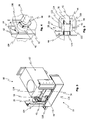
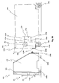
- FIG. 1 shown receiving device 10 comprises two vertical laterally arranged frame components 12 which are interconnected by a provided in the lower region of the receiving device 10 horizontal frame component 14.
- the horizontal frame component 14 is arranged on the side of the receiving device 10 facing a labeling machine (not shown).
- the horizontal frame component 14 has lateral end portions 16, which are each angled in the direction of the vertical frame components 12 and thus enclose them.
- the receiving device 10 On a side facing away from the labeling machine, the receiving device 10 has a receiving area 17 into which a module unit (in FIG. 1 not shown) can be grossed in.
- a lifting device 20 of the receiving device 10 is arranged.
- the lifting device 20 is vertically displaceable by means of two lifting gears 22, which are connected to a drive shaft 24, wherein each lifting gear 22 is in the form of a Spindelhubgetriebes, each with a spindle shaft 26 is formed.
- each lifting gear 22 is in the form of a Spindelhubgetriebes, each with a spindle shaft 26 is formed.
- FIG. 1 only one of the two screw jack 22 with spindle shaft 26 is shown.
- the motor-driven lifting drive (not shown) lies outside the receiving device 10 and is only indicated by a lateral extension of the drive shaft 24.
- the lifting device 20 comprises a lifting frame 28 with two vertically movable lifting struts 30, which are arranged on opposite sides left and right and connected by a horizontal Hubrahmenkomponente 32.
- the vertical lifting struts 30 each have an angular formation 34 for stabilizing the lifting device 20 or the lifting frame 28, the angular formation 34 each having an opening 36 for one of the spindle shafts 26.
- the lifting device 20 of the receiving device 10 comprises an engagement element 38. This extends in the first embodiment according to FIG. 1 in a horizontal position between the vertical lifting struts 30 and is each connected at one end fixed to one of the vertical lifting struts 30.
- the engagement member 38 is formed in the form of a continuous support shaft 38 having at both ends in each case a bearing bush 40 which is mounted horizontally displaceable on the support shaft 38.
- the support shaft 38 includes two shaft flanges 42 um limit the range of motion of the bushings 40 in the direction of the support shaft center point.
- a spring arrangement 44 is shown, which biases the respective bearing bush 40 horizontally into an initial position.
- a ball bearing (not shown) is provided, that in each case allows a slight low-friction displacement of the bearing bush 40 on the support shaft 38.
- the horizontal lifting frame component 32 comprises two surface sections 46 which are each angled along an edge K1 in the direction of the engagement element 38 and extend substantially parallel to the bottom plate 18.
- the surface portions 46 are formed such that one of the spindle shafts 26 is in each case guided through an opening in one of the surface portions 46.
- a spindle bearing (not shown) is mounted in the region of the respective leadthrough of the spindle shafts 26.
- a support member 48 is arranged, which comprises according to the first embodiment, a vertical cylindrical piece 50 with a support roller 52 mounted thereon.
- the entire lifting device 20 of the receiving device 10 is (not shown) via the Spindelhubantrieb or the interaction of the spindle shafts 26 with the attached to the surface portions 46 spindle bearings vertically movable.
- a rail 54 is formed on the inner sides of the vertical frame components 12.
- Each guided on the rail complementary component is formed on the respective outer side of the vertical Hubstreben 30. Due to the interaction of the guide rails 54 with the guided components of the lifting device 20, the lifting device 20 can only be moved in the vertical direction. Movements of the lifting device 20 in other directions are prevented by the rail guide, which increases the stability of the device.
- the vertical frame components 12 have tab-shaped surface portions 56 on an opposite side of the labeling machine (not shown), which are angled along an edge K2 perpendicular to the side surface of the vertical frame component 12, so that they extend substantially parallel to the horizontal Hubrahmenkomponente 32.
- a positioning member 58 is arranged in each case, according to the first embodiment a cylinder piece 60 having a roller 62 disposed thereon, the cylinder piece extending in a direction opposite to the labeling machine (not shown).
- FIG. 2 shows a module assembly 80 according to a first embodiment of the invention.
- the module assembly 80 comprises a substantially cuboidal base body 82 which is slidably supported on a substrate by means of rollers 84 fastened on its underside.
- a handle 86 is mounted on the back of the module unit 80, which projects beyond the module unit upwards.
- an opening 88 is provided in the front half.
- a positioning element 92 is mounted, which comprises a positioning surface 94 according to the first embodiment.
- the positioning elements 92 are connected, for example by means of a welding, riveting or screw connection with the respective side surface 90 of the module assembly 80.
- the positioning elements 92 are located substantially at the level of the vertical center of the module assembly 80.
- the positioning elements 92 show, in addition to the positioning surface 94, an upper surface 96 and a lower surface 98 via which the respective positioning element 92 is in contact or connected with the side surface 90 of the module assembly 80.
- the upper surface 96 and the lower surface 98 extend substantially parallel to a background (not shown) or parallel to the top and bottom of the module assembly 80 outwardly away.
- the positioning surface 94 connects each of the upper surface 96 with the lower surface 98 and is angled relative to these surfaces.
- each positioning surface 94 comprises a vertical surface portion 100 and a horizontal and vertical plane inclined surface portion 102.
- the inclination of the inclined surface portion 102 is defined by the length of the upper surface 96 and the length of the lower surface 98, the upper surface 96 a shorter As a result, the inclined surface section 102, which is located above the vertical surface section 100, is opposite to this in the direction of the main body 82 of the module assembly 80 angled.
- the inclined surface portion 102 is thus provided between the upper surface 96 and the vertical surface portion 100, while the vertical surface portion 100 is disposed between the lower surface 98 and the inclined surface portion 102.
- the module unit 80 in FIG. 2 Counter-engagement elements 104, which are each connected to a side surface 90 of the main body 82.
- the counter-engagement elements 104 in the form of grippers 104 are formed with gripping recesses 106.
- the gripping recesses 106 are also adjoined in each case by an oblique insertion surface 107.
- the grippers 104 and the gripping recesses 106 are open at the bottom.
- the counter-engagement elements 104 extend substantially parallel to each other and parallel to the side surfaces 90 of the module assembly 80 and project beyond it in the direction of the labeling machine (not shown).
- the grippers 104 are each connected via a surface piece 108 with one of the side surfaces 90 and spaced therefrom to the outside.
- the surface portion 108 extends substantially parallel to a front side 110 of the module assembly 80.
- the distance of the counter-engagement element 104 from the adjacent side surface 90 of the module assembly 80 is determined by the width of the surface portion 108.
- the sheet 108 is followed by another sheet (not shown, see, for example, FIG FIGS. 6a to 6c ), which is angled relative to the surface piece 108 and abuts in a region between the upper surface 96 and the lower surface 98 of the component 92 substantially on the respective side surface 90 of the module assembly 80.
- the grippers 104 each comprising a surface with the gripping recess 106, the surface piece 108 and the surface piece, not shown, are each formed in one piece and have substantially an S-shape viewed from above.
- a recess 114 in the front 110 of the module unit 80 is provided. This recess 114 extends in the first embodiment over the entire width of the front side and comprises approximately a height which corresponds to the height of the positioning element 92.
- the front side 110 has two counter-support elements 116 in the lower region, which are each arranged in a lateral region of the front side 110.
- the counter-supporting elements 116 according to the first embodiment comprise a circular support surface 118, which is formed substantially parallel to the front side 110 and is spaced from the front side by a distance component 120.
- FIG. 3 shows the receiving device 10 according to the in FIG. 1 illustrated embodiment and the module assembly 80 according to the in FIG. 2 illustrated embodiment, which are engaged with each other.
- the module unit 80 is located in the receiving area 17 of the receiving device 10 and the engagement element 38 in the form of the continuous horizontal support shaft 38 is on the bearing bushes 40 arranged thereon with the counter-engagement elements 104 in the form of grippers 104 into engagement.
- the lifting device 20 is raised in the state shown so far from the ground that the engagement member 38 fully engages the counter-engagement elements 104, but not far enough that the positioning elements 58 of the receiving device 10 with the positioning elements 92 and the positioning surfaces 94 (in FIG. 3 not visible) of the module assembly 80 are in contact. That is, the module aggregate 80 in the in FIG. 3 shown position on the bushings 40 is still horizontally displaceable and thus in this state is not yet aligned relative to the labeling machine (not shown).
- the recess 114 in the front 110 of the module assembly 80 is formed such that when the module assembly 80 is engaged with the receiving device 10, the engagement member 38 in the form of the continuous support shaft 38 in the area the recess 114 is located.
- the recess 114 has a depth and width which are sufficiently large that the engagement element 38 or the continuous support shaft 38 does not come into contact with the base body 82 of the module assembly 80. This applies both to the time when the module assembly 80 is moved up to the receiving device 10 without the engagement member 38 and the counter-engagement member 104 are engaged, as well as for the time when the engagement member 38 and the counter-engagement member 104 partially or fully engaged stand.
- FIG. 3 shows how the counter-supporting element 116 is supported via the supporting surface 118 relative to the roller 52 of the supporting element 48 of the receiving device 10.
- the arrangement of the roller 52 and the support surface 118 of the Gegenab resultslements 116 at the same time prevents tilting of the module assembly 80 about a longitudinal axis of the engagement member and a light, low-friction horizontal displacement of the module unit 80 allows.
- FIG. 3 the area marked E is in FIG. 4 shown enlarged.
- This area shows a section of the engagement element 38 and one of the counter-engagement elements 104 and grippers 104, which engage with each other.
- the engagement element 38 of the receiving device 10 engages over the bearing bush 40 in the gripping recess 106 of the counter-engagement element 104 of the module assembly 80 a.
- the engagement element 38 and the counter-engagement element 104 are in FIG. 4 state shown in complete engagement with each other.
- the recess 106 of the counter-engagement element 104 is congruent with the bearing bush 40, and therefore, in the state of complete engagement, no gap or gap is provided between the gripping recess 106 and the bearing bush 40.
- FIG. 4 the spring assembly 44 between the bearing bush 40 and the shaft flange 42 and between the bearing bush 40 and the vertical frame component 12 is shown clearly.
- the spring arrangement 44 determines the position of the bearing bush 40 relative to the counter-engagement element 104 of the module assembly, before the engagement element 38 engages in the counter-engagement element 104. At the same time, however, the spring assembly 44 does not interfere with the horizontal movement of the bushing 40 or module assembly 80 when the engagement member 38 engages the mating engagement member 104.
- FIG. 5 An enlarged partial sectional view of the in FIG. 3 marked area E is in FIG. 5 shown.
- a linear ball bearing 122 is shown, which is arranged between the continuous support shaft 38 and the bearing bush 40.
- the linear ball bearing 122 is attached via two retaining rings 124 in the bearing bush.
- the retaining rings 124 are each arranged at one end of the linear ball bearing 122.
- the positioning member 92 having the upper surface 96, the lower surface 98, and the vertical surface portion 100 is shown.
- the inclined surface portion 102 is hidden in this view.
- FIG. 5 It can also be seen that the engagement element 38 in the in FIG. 3 shown state in complete engagement with the counter-engagement element 104, but without the module unit is so far raised from the ground that the positioning member 58 of the receiving device 10 is in contact with the positioning surface 94 and the inclined surface portion 102 or the vertical surface portion 100.
- the module unit 80 described above can be received by the receiving device 10.
- the module assembly 80 is roughly moved into the receiving area 17 of the receiving device 10. An exact positioning is not required.
- the lifting device 20 is moved vertically upwards, whereby the engagement element 38 engages with the counter-engagement element 104.
- the module assembly 80 is first pushed away from the labeling machine (not shown) or the receiving device 10.
- an alternative embodiment of the insertion surfaces 107 is possible, by which the module unit 80 is first used in the direction of the labeling machine to the receiving device 10. After pushing away or pulling the module unit 80 is lifted by means of the lifting device 20 of the receiving device 10 from the ground.
- the module assembly 80 during the engagement of the engagement element 38 in the counter-engagement element 104 and also immediately after a complete intervention further horizontally displaceable. This applies until the positioning elements 58 of the receiving device 10 come into contact with the complementary positioning elements 92 or positioning surfaces 94 of the module assembly 80. As a result of the interaction of one of the positioning elements 58 with the corresponding inclined surface section 102, the module assembly 80 is optionally displaced horizontally during lifting and aligned horizontally relative to the labeling machine. This will be discussed in detail below.
- the module assembly 80 is completely aligned horizontally and fixed in its horizontal position. From this point on, only a vertical displacement of the module assembly 80 by a further raising or lowering of the lifting device 20 is possible, as long as the positioning elements 58 are in contact with the vertical surface portions 100 of the positioning elements 92.
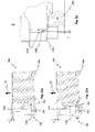
- FIGS. 6a, 6b and 6c show the process of aligning the module assembly 80 according to the in FIG. 1 shown embodiment when lifting the module assembly 80 (see vertical arrow PV).
- the FIGS. 6a to 6c each show a sectional view of the receiving device 10 according to the in FIG. 1 shown embodiment and the module assembly 80 according to the in FIG. 2 shown embodiment, which engage with each other, wherein of the receiving device 10, only the two positioning elements 58 and some frame components are shown.
- FIG. 6a shows the in FIG. 3 illustrated state, after which the module unit 80 is already received by the receiving device 10.
- the engagement member (not shown) is fully engaged with the mating engagement member (not shown).
- the rollers 84 of the module assembly 80 no longer touch the ground in this state, which means that the module unit 80 is already raised.
- the positioning elements 58 are still at least partially above the positioning element 92 and the positioning surface 94.
- the module assembly 80 is further horizontally displaceable in this state and the automatic alignment of the module assembly relative to the labeling has not yet begun in this state.
- FIG. 6b shows another state of the module assembly 80 during horizontal alignment relative to the labeling machine at a time later than the time of the state FIG. 6a ,
- the module assembly 80 is already raised further from the ground, so that the positioning surface 94 in the region of the inclined surface portion 102 on one side of the module assembly 80 (here on the real side) is in contact with the corresponding positioning member 58 of the receiving device 10.
- FIG. 6b also shows that the module unit 80 is opposite to the state in FIG. 6a is offset horizontally (see horizontal arrow PH). This offset may be due to a horizontal displacement of the module assembly 80 during lifting, for example due to an uneven ground. Alternatively, however, it is also conceivable that the module assembly 80 already in the introduction of the module assembly 80 in the receiving area 17 of the receiving device 10 in FIG. 6b shown position (unlike in FIG. 6a shown).
- the inclined surface portion 102 contacting the positionally fixed positioning member 58 cooperates with the roller 62 of the corresponding positioning member 58. Due to the inclination of the inclined surface portion 102 and the further vertical lifting of the module assembly 80, the horizontally displaceable module unit 80 is displaced horizontally in the direction of the non-contacting positioning element 58. This creates an automatic horizontal alignment and positioning relative to the labeling (horizontal arrow PH).
- FIG. 6c shows a further state of the module unit 80 during lifting, the time after the in FIG. 6b shown state is.
- the module assembly 80 is in the in FIG. 6c shown state again raised from the ground.
- the module unit 80 is completely fixed in its horizontal position and thus aligned horizontally relative to the labeling.
- FIG. 6c shows that the distance between the positioning elements 58 of the receiving device 10 substantially corresponds to the distance between the vertical surface portions 100 of the module assembly 80.
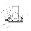
- FIG. 7 shows a plan view of the in FIG. 3 shown receiving device 10 and the module assembly 80, which are engaged with each other.
- the components 126 guided on the rails 54 are shown here.
- the guided components 126 are designed such that they undercut the respective rail 54. Since the guided components 126 are firmly connected to the lifting device 20 of the receiving device 10 or to the vertical lifting struts 30, thus only a vertical movement of the lifting device 20 is allowed.
- FIG. 7 also shows that the distance between the positioning elements 58 and the rollers 62 of the positioning elements 58 substantially corresponds to the distance between the vertical surface portions 100 of the positioning surfaces 94 of the module assembly 80. Accordingly, the horizontal position of the module assembly is completely fixed relative to the labeling machine as soon as the positioning elements 58 are in contact with the vertical surface portions 100 of the module assembly 80 on both sides.
- FIG. 8 shown receiving apparatus 10a according to a second embodiment
- the structure of the receiving device according to the above first embodiment is similar, will be discussed here only on the differences between the two embodiments.
- a holding shaft section 38a is in each case arranged on one side of the lifting device 20a and firmly connected to the respective adjacent vertical lifting strut 30a.
- the two holding shaft sections 38a extend in each case starting from the adjacent vertical lifting strut 30a in the direction of the receiving region 17a of the receiving device 10a.
- the two holding shaft sections 38a are each formed substantially parallel to the bottom plate 18a.
- the shaft portions 38a of the second embodiment also have a shaft flange 42a, respectively.
- the shaft flange 42a is in each case placed on the end of the respective holding shaft section 38a facing away from the vertical lifting frame component 30a and thus closes off the respective holding shaft section 38a.
- the support shaft portions 38a extend thus each between one of the vertical lifting strut 30a and a shaft flange 42a.
- the support shaft portions 38a of the second embodiment are each provided with a bushing 40a horizontally slidable on the respective support shaft portion 38a and spring-biased by a spring assembly 44a between the adjacent vertical lift frame component 30a and the adjacent shaft flange 42a.
- FIG. 9 shows a module assembly 80a according to a second embodiment, the structure of which is similar to the structure of the module assembly 80 according to the first embodiment, which is why in the following only the differences between the two embodiments will be discussed.
- module assembly 80a has at its side surfaces 90a in the front, the labeling machine facing region each have a recess 114a, which is respectively disposed at the level of the positioning elements 92a and the positioning surfaces 94a and the counter-engagement element 104a.
- the lateral recesses 126a each extend from the front side 110a of the module assembly 80a to the adjacent positioning member 92a.
- the height of the recesses 114a corresponds in each case approximately to the height of the component 92a, wherein the height decreases slightly, starting from the front side 110a in the direction of the component 92a.
- the depth of the recesses 114a in the direction of the Modulaggregatmitte is in each case to the length of the complementary engagement elements 38a of the receiving device 10a according to FIG. 8 customized.
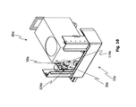
- FIG. 10 shows the receiving device 10a according to the in FIG. 8 shown second embodiment and the module assembly 80a according to the in FIG. 9 shown second embodiment, which are engaged with each other. It shows FIG. 10 the same condition as FIG. 3 in that the engagement member 38a fully engages the mating engagement member 104a, but the module assembly 80a is not yet raised enough from the ground that the positioning members 58a are in contact with the positioning surface 94a of the module assembly 80a. Thus, the module unit 80a is still horizontally displaceable in this state.
- FIG. 10 it is shown how the retaining shaft sections 38a extend into the respective lateral recess 114a upon complete engagement of the engagement elements 38a and counter engagement elements 104a. It can also be seen from this illustration that the height of the lateral recesses 114a is large enough It must be understood that the retaining shaft sections 38a can already extend without contact into the lateral recesses 114a when the module assembly 80a approaches the receiving device 10a.
- FIG. 11 shows a receiving device 10b according to a third embodiment of the invention.
- the receiving device 10b likewise comprises two laterally arranged vertical frame components 12b, which are respectively supported by two feet 130b with respect to the ground.
- these feet 130b may also be firmly screwed to the substrate.
- the frame components 12b each have a rail 54b in an area facing the labeling machine (not shown).
- the lifting device 20b according to this third embodiment, some alternative embodiments of the first two embodiments.
- the lifting device 20b comprises a horizontally arranged lifting frame component 30b which engages with the rails 54b via the guided components 126b.
- the lift frame component 30b is thus disposed adjacent to the vertical frame components 12b substantially between them and the labeling machine (not shown).
- the lift frame component 30b each includes two guided components 126b at the left and right ends of a surface facing the vertical frame components 12b. Accordingly, the lifting frame component 30b extends in a horizontal manner over a length which substantially corresponds to the distance between the two vertical frame components 12b of the receiving device 10b.
- the lifting device 20b is vertically movable by means of a lifting drive, wherein the lifting drive or the components of the lifting drive in FIG. 11 are not shown.
- the illustration shows two vertical profiles 132b which are mounted on a surface of the lifting frame component 30b facing away from the labeling machine.
- these vertical profiles 132 may include spindle bearings (not shown) which may cooperate with a spindle drive (not shown).
- the vertical profiles 132 act in sections as a support element for cooperation with complementary Jacobab spalementen a module aggregate.
- the engagement members 38b are fixedly connected to the lift frame component 30b by a welded joint, for example, and extend substantially parallel to the side frame components 12b and are spaced from each other.
- the grippers 38b each have a gripping recess 134b and an insertion surface 136b.
- the grippers 38b correspond in this embodiment in their embodiment substantially in FIG. 2 shown grippers 104 of the module assembly 80, however, the grippers 38b on an upward opening.
- a holding device 138b is mounted in a lower region of the two frame component 12b with an insertion roller 140b mounted therein.
- the insertion rollers 140b are each arranged substantially parallel to the substrate.
- the lateral frame components 12b each comprise two positioning elements 58b, which according to the third embodiment are designed in the form of a positioning element pair.
- a positioning element 58b in each case consists of a positioning roller 142b, which is respectively mounted in a holding device 144b and fixedly connected thereto by the respective frame component 12b.
- the positioning roller 142b is arranged in each case substantially parallel to the lifting frame component 30b.
- the two positioning elements 58b of a positioning element pair are spaced apart horizontally and vertically.
- FIG. 12 shows a module assembly 80b, which comprises a base body 82b, which is supported on rollers 84b on the ground and moved.
- the main body 82b On a front side 110b facing the labeling machine in the operating state, the main body 82b has two narrow trapezoidal bodies 150b, which extend the main body 82b via the front side 110b.
- a trapezoidal body 150b is arranged in the left and right edge region of the front side 110b, so that the respective outer sides of the trapezoidal body follow the respectively adjacent side surface 90b of the main body 82b extend the front.
- the trapezoidal bodies 150b are substantially parallel to each other and spaced from each other.
- the trapezoidal bodies 150b terminate upwardly with the upper surface of the main body 82b, but are shorter in a vertical extent than the main body 82b.
- the end faces 152b of the two trapezoidal bodies 150b are formed substantially parallel to the front side 110b of the module assembly 80b.
- the width of the trapezoidal bodies 150b slightly decreases with the distance from the front side 110b.
- the end faces 152b of the trapezoidal bodies 150b each have, in a lower region, a counter-support element 116b in the form of a circular surface.
- the continuous support shaft is formed substantially parallel to the ground or to the top and bottom of the main body 82b. Furthermore, the continuous support shaft is arranged approximately in the middle of the inner side surfaces 154b of the two trapezoidal bodies 150b.
- the counter-engagement element 104b in the form of the continuous support shaft extends over the entire width of the module assembly 80b, so that the two ends of the support shaft 104b are each mounted in one of the trapezoidal bodies 150b.
- the two trapezoidal bodies 150b each have a corresponding opening 156b.
- the bearing of the support shaft 104b is realized via bearing bushes 40b which are arranged between the ends of the support shaft 104b and the respective trapezoid body 150b on the shaft.
- the bearing bushes 40b are fixedly connected to the associated trapezoidal body 150b (not shown) and supported by a ball bearing (not shown) on the support shaft, so that the support shaft 104b is horizontally displaceable.
- the range of horizontal displaceability of the support shaft 104b can also be determined, for example, by securing elements or shaft flanges (not shown).
- the module assembly 80b comprises on its side surfaces 90b a positioning element 92b with a positioning surface 94b, the positioning surface 94b each comprising two adjoining vertical surface sections 100b and two inclined surface sections 102b.
- the vertical surface portions 100b extend substantially parallel to the respective side surface 90b and are spaced therefrom and connected thereto via the inclined surface portions 102b, respectively.
- the inclined surface portions 102b in this embodiment directly connected to the associated side surface 90b.
- the vertical surface portion 100b closer to the front side 100b has a greater height than the more distant vertical surface portion 100b.
- FIG. 13 shows a receiving device 10c according to a fourth embodiment of the invention.
- the receiving device 10c essentially corresponds to the receiving device 10b according to FIG. 11 .
- the lifting device 20c in particular the horizontal lifting frame component 30c, is formed in two parts, ie separated from one another.
- the lifting device 20c has a gap 158c extending between the two engaging elements 38c.
- FIG. 14 shows a module assembly 80c according to a fourth embodiment of the invention.
- the module unit 80c substantially corresponds to the one in FIG FIG. 12 shown module assembly 80b according to the third embodiment of the invention.
- module assembly 80c unlike module assembly 80b, does not have a counter-engagement element in the form of a continuous support shaft, but instead comprises two counter-engagement elements 104c, which are each in the form of a support shaft section.
- the holding shaft sections 104c each extend from an inner side surface 154c of the trapezoidal bodies 150c in the direction of the respectively opposite inner side surface 154c. In this case, the holding shaft sections 104c are each formed substantially parallel to the ground.
- the support shaft portions 104c of the mating engagement member 104c are not supported in the trapezoidal bodies 150c, but are fixedly connected to the respective side surface 154c by a shaft flange 42c on one side.
- the holding shaft sections 104c are each firmly connected to a holding component 160c.
- the holding components 160c each extend substantially parallel to the inner side surface 154c and are fixedly connected to the front side 110c of the main body 82c of the module assembly 80c.
- a bearing bush 40c is provided on the two holding shaft sections 104c and can be displaced horizontally on the respective holding shaft section 104c is arranged.
- a spring arrangement 44c is provided, which biases the bearing bush 40c.
- the vertical surface portion 100b closer to the front side 100b has a lower height than the more distant vertical surface portion 100b.
- FIG. 15 shows a plan view of the module assembly 80c according to the in FIG. 14 illustrated embodiment.
- the two positioning surfaces 94c only the inclined surface portions 102c are visible on both sides of the module assembly 80c.
- the spring assembly 44c and the bearing bushes 40c which are arranged on the support shaft sections, better visible.
- FIG. 16 shows a section AA of in FIG. 15 module unit 80c shown.
- the illustration indicates a region B, in which the bearing of the bearing bushes 40c is shown in more detail on the support shaft sections.
- Area B is also in FIG. 17 shown enlarged and shows in detail how the bushings 40 c are mounted horizontally displaceable on the support shaft sections.
- a ball bearing 122c is arranged between the bearing bush 40c and the holding shaft section.
- the bearing bush 40c has side openings 162c in which springs of the spring assembly 44c engage and thereby the bearing bush 40c is biased relative to the support component 160c and a shaft flange 42c.
- the shaft flange 42c is formed on an end of the holding shaft section opposite the holding component 160c.
- the support shaft sections can be connected via a weld, screw or other connection firmly with the adjacent trapezoidal body 150c.
- FIG. 18 shows a receiving device 10d according to a fifth embodiment of the invention. Since the construction of in FIG. 18 Shown recording device 10d is similar to the structure of the receiving device 10b according to the third embodiment, will be discussed only differences between these two embodiments.
- the receiving device 10d according to the fifth embodiment shows a guide rail 164d provided on the receiving device 10d.
- the guide rail 164d is disposed below the engagement members 38d on the horizontal lift frame component 30d. In this case, the guide rail 164d extends substantially parallel to the ground.
- the carriage 166d On the guide rail 164d two slidably mounted carriage 166d are arranged.
- the carriage 166d are each connected via linear guides with the guide rail 164d. Since linear guides require a certain amount of load to ensure easy running, the carriages 166d may be fixed in an unloaded state in their relative position on the guide rail 164d or biased to an initial position.
- the carriages 166d are spaced from each other in the embodiment shown and arranged with respect to counter-supporting elements of a corresponding modular unit.
- the carriages 166d each have a supporting element 48d in the form of a plate. Since the support members 48d according to the fifth embodiment are formed in the manner described, in the illustrated embodiment, vertical profiles 132b, 132c (see FIG Figures 11 and 13 ), which can act in sections as support elements omitted.
- FIG. 19 shows a module assembly 80d according to a fifth embodiment. Since the module unit 80d according to the fifth embodiment is substantially similar to the module unit 80b according to the third embodiment, only differences between the two embodiments will be discussed below.
- the module assembly 80d includes a rail 168d.
- the rail 168d is fixedly connected at each end in a lower region of a front side 152d of the trapezoidal body 150d of the module assembly 80d with the module assembly 80d.
- the rail 168d extends substantially parallel to the front side 110d of the module assembly 80d.
- the rail 168d is connected substantially in the regions of the end faces 152d of the trapezoidal bodies 150d to the module assembly 80d, in which the module assembly 80b according to the third embodiment (FIG. FIG. 12 ) each having a symbols 116b.
- the module assembly 80d according to the fifth embodiment has no counter-supporting elements on the end faces 152d of the trapezoidal bodies 150d.
- the counter-supporting elements 116d are in the in FIG. 19 embodiment shown in the form of bolts 170d on the rail 168d.
- the Jacobab 100b are spaced from each other and extend beyond the rail 168d and thus the module assembly 80d in the direction of the labeling machine (not shown).
- the end faces of the bolts 170d in the direction of the labeling machine each form a support surface 118d.
- the counter-support elements 116d of the module assembly 80d can interact with the support elements 48d of the receiving device 10d during the lifting of the module assembly 80d.
- the linear guides of the carriages 166d mounted on the guide rail 164d are loaded thereby, whereby a slight displacement of the carriages 166d on the guide rail 164d is made possible.
- the horizontal alignment of the module assembly 80d during the further lifting of the module assembly 80d by means of the receiving device 10d is positively supported.
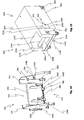
- FIG. 20 shows the receiving device 10b according to the third embodiment and a module assembly 80e according to a sixth embodiment in a side view.
- the inclination of the module assembly 80e along the longitudinal axis of the module assembly 80e by the angle X can be seen.
- the inclination of the module assembly and the resulting consequences and features in the FIGS. 20 to 22 by way of example on the module assembly 80e according to the sixth embodiment in cooperation with the receiving device 10b according to the third embodiment.
- the module assemblies 80, 80a, 80b, 80c, 80d of the previously described embodiments may also be formed with a corresponding inclination.
- the inclination of the module assembly 80e results from the height difference or the levels of storage between an area of the module assembly 80e facing the labeling machine and an area of the module assembly 80e facing away from the labeling machine. This difference in height leads to the inclination angle X, wherein the region of the module assembly 80e facing away from the labeling machine is higher than the labeling of the machine facing away from the module unit 80e.
- the module unit 80e has two rollers 80e, both in the region facing the labeling machine and in the region facing away from the labeling machine, via which the module assembly 80e is supported relative to the substrate.
- FIG. 20 shows the module assembly 80e in a state in which all rollers 84e are in contact with the ground. Further, the module aggregate 80e is in FIG. 20 spaced from the receiving device 10b and thus is not yet engaged with the receiving device 10b.
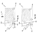
- FIGS. 21a, 21b . 21c and 21d show in a sectional side view the process of lifting the module assembly 80e by the receiving device 10b (see vertical arrow PV).
- the illustrated process particularly shows the effects of lifting the module assembly 80e with respect to the described inclination of the module assembly 80e.
- the in the FIGS. 6a to 6c The process of horizontal alignment when lifting is shown in FIG FIGS. 21a to 21d not apparent. However, also when lifting the module assembly 80e according to the FIGS. 21a to 21d a horizontal alignment of the module assembly 80e according to the in the FIGS. 6a to 6c process shown instead.
- FIG. 21a shows the module assembly 80e, which is introduced into the receiving area 17b of the receiving device 10b.
- the engagement element 38b and the counter-engagement element 104e do not engage in one another in the state shown.
- the rollers 84e of the module assembly 80e touch in this state still completely the ground.
- the module unit 80e is not yet lifted from the ground and is therefore still in the FIG. 20 already explained angle X inclined.
- FIG. 21b shows another state of the module aggregate 80e during the lifting of the module 80e at a time later than the time of the state FIG. 21a , In this state, the engagement member 38b and the counter engagement member 104e are fully engaged with each other. However, in the state shown, no lifting of the module assembly 80e from the ground has yet taken place. All rollers 84e of the module assembly 80e continue to completely contact the ground, which is why the module assembly 80e is further inclined by the angle X in this state.
- FIG. 22 shows the resulting from the inclination distance Y of the Gegenab 100 e of the component 132 b receiving device 10 b.
- FIG. 21c shows a further state of the module unit 80e when lifting, the time after the in FIG. 21b shown state is.
- the module unit 80e is already partially raised from the ground.
- the rollers 84e in the area facing the labeling machine are raised from the ground by a distance Z, while the rollers 84e continue to completely contact the ground in the region facing away from the labeling machine.
- the distance Z compensates in this state substantially the angle X, whereby the inclination is substantially balanced in the representation shown.
- the longitudinal axis of the module assembly 80e is substantially parallel to the ground.
- Figure 21d shows a further state of the module unit 80e when lifting, the time after the in FIG. 21c shown state is.
- the module unit 80e is raised completely from the ground in the state shown. None of the rollers 84e touches the ground in this state.
- the module unit 80e points in Furthermore, this state has no inclination along the longitudinal axis of the module assembly 80e.
- the lateral (horizontal) alignment along the direction of the support shaft 104d is as described above.
- FIGS. 21a, 21b . 21c and 21d This shows the FIGS. 21a, 21b . 21c and 21d in that the inclination of the module assembly 80e when lifting by the receiving device 10b is compensated for without requiring manual intervention.
- FIG. 23 shows a flange 200 between a receiving device 10 b and a table top 300 of a labeling machine (not shown), wherein the table top 300 is shown only in fragmentary form.
- the receiving device 10b according to the third embodiment is shown.
- the flange connection 200 can also be used with the receiving devices of the further embodiments and, alternatively, can also be attached to the periphery of the labeling machine via a component other than the tabletop 300.
- the flange connection 200 shown is formed as a separate plate-shaped component separated from the receiving device 10 b and the table top 300.
- the flange connection has on a side surface 202 facing the table top 300 in operation a curved contour on which a spring 204 is formed.
- the curve shape and the spring 204 of the contour are adapted to an associated portion of an outer peripheral surface 302 of the table top 300, which is provided with a corresponding groove 304 to allow a precise and firm connection between the connecting flange 200 and the table top 300.
- the spring portion 204 in a portion of the groove 304 the flange 200 is fixed relative to the table top 300 vertically.
- the fixed connection is realized in the embodiment shown by means of a screw connection.
- the flange connection 200 comprises three horizontal bores 206, which are in each case aligned coaxially with corresponding threaded bores 306 in the groove 304 of the table top 300.
- a screw 208 of this screw connection is shown, which is screwed through one of the bores 206 into one of the threaded bores 306.
- two vertical bores 210 are formed in the flange connection 200, which each extend coaxially to an associated bore 188b at a connecting section 190b of the receiving device 10b during operation.
- a pin 212 can be introduced (in FIG. 23 only one pin is shown by way of example) in order to fix the receiving device 10b at least in the radial and tangential direction relative to the table top 300.
- planar connecting portion 190b of the receiving device 10b two recesses 192b are formed, which are each engageable with a projection (not shown) provided on a planar underside of the flange connection, which is indicated by the dashed line in FIG FIG. 23 is indicated.
- the planar underside of the flange joint 200 can be brought into abutting engagement with the connecting portion 190b of the receiving device 10b, whereby corresponding bores 210, 188b of the flange connection 200 and the receiving device 10b are aligned coaxially with each other, which assists easy and quick assembly.
- the number of holes in the flange joint 200, the connecting portion 190b of the receiving device 10b and the table top 300 may also differ from the respective number mentioned above.
- FIG. 24a shows the circular table top 300 of the labeling machine, which has a central recess 308 for a drive shaft (not shown) of a carousel of the labeling machine.
- a central recess 308 for a drive shaft (not shown) of a carousel of the labeling machine On the outer peripheral surface 302 of the table top 300, in turn, the plurality of spaced-apart threaded bores 306 can be seen. About these threaded holes 306 receiving devices for modular units at the periphery of the labeling machine can be attached at any position.
- FIG. 24b A detail view of the detail F of the table top 300 is in FIG. 24b shown enlarged. It is shown that the threaded holes 306 are formed in the groove 304, which extends along the outer peripheral surface 302 of the table top.
- the groove 304 extends radially inwardly from the outer peripheral surface 302 with respect to the rotational axis of the table top 300, with a region of the outer peripheral surface 302 being formed above and below the groove 304.
Landscapes
- Labeling Devices (AREA)
Applications Claiming Priority (1)
| Application Number | Priority Date | Filing Date | Title |
|---|---|---|---|
| DE102014015810.1A DE102014015810B3 (de) | 2014-10-24 | 2014-10-24 | Anordnung umfassend eine Aufnahmevorrichtung für eine Etikettiermaschine und ein Modulaggregat sowie Verfahren zum Positionieren eines Modulaggregats an einer Etikettiermaschine |
Publications (2)
| Publication Number | Publication Date |
|---|---|
| EP3012204A1 true EP3012204A1 (fr) | 2016-04-27 |
| EP3012204B1 EP3012204B1 (fr) | 2020-12-09 |
Family
ID=54359676
Family Applications (1)
| Application Number | Title | Priority Date | Filing Date |
|---|---|---|---|
| EP15003014.6A Active EP3012204B1 (fr) | 2014-10-24 | 2015-10-21 | Dispositif de reception pour une etiqueteuse et monobloc |
Country Status (2)
| Country | Link |
|---|---|
| EP (1) | EP3012204B1 (fr) |
| DE (1) | DE102014015810B3 (fr) |
Cited By (1)
| Publication number | Priority date | Publication date | Assignee | Title |
|---|---|---|---|---|
| WO2020108823A1 (fr) * | 2018-11-27 | 2020-06-04 | Krones Ag | Module d'amarrage et étiqueteuse |
Families Citing this family (2)
| Publication number | Priority date | Publication date | Assignee | Title |
|---|---|---|---|---|
| DE202016105934U1 (de) | 2016-10-21 | 2017-08-22 | Krones Ag | Andockstation für ein Etikettieraggregat |
| DE102024128667A1 (de) * | 2024-10-02 | 2026-04-02 | Khs Gmbh | Vorrichtung und System zum Tragen mindestens eines Behälterbehandlungsmoduls |
Citations (7)
| Publication number | Priority date | Publication date | Assignee | Title |
|---|---|---|---|---|
| EP1412279B1 (fr) | 2001-09-14 | 2004-11-03 | Krones Ag | Machine d'etiquetage |
| DE202006002729U1 (de) * | 2006-02-21 | 2006-04-13 | Khs Ag | Maschine zum Ausstatten von Flaschen o.dgl. Behälter, insbesondere Etikettiermaschinen |
| JP2009241208A (ja) * | 2008-03-31 | 2009-10-22 | Panasonic Corp | 作業装置及び作業機 |
| EP1706323B9 (fr) | 2004-01-19 | 2011-02-02 | Krones Aktiengesellschaft | Machine d'étiquetage d'articles |
| WO2012117426A1 (fr) * | 2011-02-28 | 2012-09-07 | Kosme S.R.L. Unipersonale | Machine d'étiquetage à dispositif d'étiquetage amovible |
| WO2013007317A1 (fr) * | 2011-07-13 | 2013-01-17 | P.E. Labellers S.P.A. | Chariot de support pour poste d'étiquetage de machine d'étiquetage |
| WO2013131587A1 (fr) | 2012-03-07 | 2013-09-12 | P.E. Labellers S.P.A. | Machine d'étiquetage à carrousel |
-
2014
- 2014-10-24 DE DE102014015810.1A patent/DE102014015810B3/de active Active
-
2015
- 2015-10-21 EP EP15003014.6A patent/EP3012204B1/fr active Active
Patent Citations (8)
| Publication number | Priority date | Publication date | Assignee | Title |
|---|---|---|---|---|
| EP1412279B1 (fr) | 2001-09-14 | 2004-11-03 | Krones Ag | Machine d'etiquetage |
| EP1553045A1 (fr) | 2001-09-14 | 2005-07-13 | Krones AG | Machine d'étiquetage modulaire |
| EP1706323B9 (fr) | 2004-01-19 | 2011-02-02 | Krones Aktiengesellschaft | Machine d'étiquetage d'articles |
| DE202006002729U1 (de) * | 2006-02-21 | 2006-04-13 | Khs Ag | Maschine zum Ausstatten von Flaschen o.dgl. Behälter, insbesondere Etikettiermaschinen |
| JP2009241208A (ja) * | 2008-03-31 | 2009-10-22 | Panasonic Corp | 作業装置及び作業機 |
| WO2012117426A1 (fr) * | 2011-02-28 | 2012-09-07 | Kosme S.R.L. Unipersonale | Machine d'étiquetage à dispositif d'étiquetage amovible |
| WO2013007317A1 (fr) * | 2011-07-13 | 2013-01-17 | P.E. Labellers S.P.A. | Chariot de support pour poste d'étiquetage de machine d'étiquetage |
| WO2013131587A1 (fr) | 2012-03-07 | 2013-09-12 | P.E. Labellers S.P.A. | Machine d'étiquetage à carrousel |
Cited By (1)
| Publication number | Priority date | Publication date | Assignee | Title |
|---|---|---|---|---|
| WO2020108823A1 (fr) * | 2018-11-27 | 2020-06-04 | Krones Ag | Module d'amarrage et étiqueteuse |
Also Published As
| Publication number | Publication date |
|---|---|
| EP3012204B1 (fr) | 2020-12-09 |
| DE102014015810B3 (de) | 2016-03-31 |
Similar Documents
| Publication | Publication Date | Title |
|---|---|---|
| DE69515411T2 (de) | Verfahren und Vorrichtung zum Biegen von Glasscheiben | |
| DE69619227T2 (de) | Vorrichtung zum Zuführen langer Werkstücke | |
| DE2930618A1 (de) | Endstellungs-steuervorrichtung | |
| DE4015471A1 (de) | Mobiles patientenlagersystem | |
| EP3048402B1 (fr) | Dispositif de changement de rouleau porteur | |
| EP0501254A2 (fr) | Table élévatrice à ciseaux | |
| DE3142378A1 (de) | "maschine zur selbsttaetigen montage von reifen auf felgen" | |
| DE60117510T2 (de) | Hebestütze für eine Blechbiegemaschine | |
| EP3012204B1 (fr) | Dispositif de reception pour une etiqueteuse et monobloc | |
| DE2658137B2 (de) | Wälzschere | |
| EP0063253A2 (fr) | Dispositif pour aligner et centrer automatiquement des pièces à usiner | |
| DE2638325C2 (fr) | ||
| DE3035657A1 (de) | Vorrichtung zum haltern von werkstuecken | |
| DE102020133203A1 (de) | Richtmaschine und Verfahren zum Inspizieren, Warten oder Ersetzen von Stützrollen in einer Richtmaschine | |
| DE69101457T2 (de) | Vorrichtung zum Eindrücken und Schneiden in Längsrichtung eines laufenden Materialbandes. | |
| DE2159113A1 (de) | Vorrichtung zum Auswechseln der Arbeitswalzen von Walzgerüsten | |
| DE102010029566B4 (de) | Regal mit Zentrierungsrollen | |
| EP0129089B1 (fr) | Appareil pour le transport des pots de ruban de fibres | |
| DE2744717A1 (de) | Brennschneidmaschine | |
| DE102017119523A1 (de) | Hebevorrichtung für eine im Kofferraum eines Fahrzeugs angeordnete Antriebsbatterie und Fahrzeug mit solcher Hebevorrichtung | |
| EP1134151B1 (fr) | Procédé de levage de supports inclus dans une chaîne de transport entraînée et chaîne de montage utilisant ce procédé | |
| EP2368647B1 (fr) | Système comprenant un support de cylindres et un dispositif de changement de cylindres | |
| EP0296151B1 (fr) | Dispositif avec cadre de levage pour l'usinage de pieces | |
| DE202019102217U1 (de) | Scherenhubtischsystem | |
| DE2845051A1 (de) | Walzwerk mit auswechselbaren geruesten |
Legal Events
| Date | Code | Title | Description |
|---|---|---|---|
| PUAI | Public reference made under article 153(3) epc to a published international application that has entered the european phase |
Free format text: ORIGINAL CODE: 0009012 |
|
| 17P | Request for examination filed |
Effective date: 20151021 |
|
| AK | Designated contracting states |
Kind code of ref document: A1 Designated state(s): AL AT BE BG CH CY CZ DE DK EE ES FI FR GB GR HR HU IE IS IT LI LT LU LV MC MK MT NL NO PL PT RO RS SE SI SK SM TR |
|
| AX | Request for extension of the european patent |
Extension state: BA ME |
|
| STAA | Information on the status of an ep patent application or granted ep patent |
Free format text: STATUS: EXAMINATION IS IN PROGRESS |
|
| 17Q | First examination report despatched |
Effective date: 20171221 |
|
| GRAP | Despatch of communication of intention to grant a patent |
Free format text: ORIGINAL CODE: EPIDOSNIGR1 |
|
| STAA | Information on the status of an ep patent application or granted ep patent |
Free format text: STATUS: GRANT OF PATENT IS INTENDED |
|
| INTG | Intention to grant announced |
Effective date: 20200710 |
|
| GRAS | Grant fee paid |
Free format text: ORIGINAL CODE: EPIDOSNIGR3 |
|
| GRAA | (expected) grant |
Free format text: ORIGINAL CODE: 0009210 |
|
| STAA | Information on the status of an ep patent application or granted ep patent |
Free format text: STATUS: THE PATENT HAS BEEN GRANTED |
|
| AK | Designated contracting states |
Kind code of ref document: B1 Designated state(s): AL AT BE BG CH CY CZ DE DK EE ES FI FR GB GR HR HU IE IS IT LI LT LU LV MC MK MT NL NO PL PT RO RS SE SI SK SM TR |
|
| REG | Reference to a national code |
Ref country code: GB Ref legal event code: FG4D Free format text: NOT ENGLISH |
|
| REG | Reference to a national code |
Ref country code: AT Ref legal event code: REF Ref document number: 1343201 Country of ref document: AT Kind code of ref document: T Effective date: 20201215 Ref country code: CH Ref legal event code: EP |
|
| REG | Reference to a national code |
Ref country code: DE Ref legal event code: R096 Ref document number: 502015013966 Country of ref document: DE |
|
| REG | Reference to a national code |
Ref country code: IE Ref legal event code: FG4D Free format text: LANGUAGE OF EP DOCUMENT: GERMAN |
|
| PG25 | Lapsed in a contracting state [announced via postgrant information from national office to epo] |
Ref country code: FI Free format text: LAPSE BECAUSE OF FAILURE TO SUBMIT A TRANSLATION OF THE DESCRIPTION OR TO PAY THE FEE WITHIN THE PRESCRIBED TIME-LIMIT Effective date: 20201209 Ref country code: RS Free format text: LAPSE BECAUSE OF FAILURE TO SUBMIT A TRANSLATION OF THE DESCRIPTION OR TO PAY THE FEE WITHIN THE PRESCRIBED TIME-LIMIT Effective date: 20201209 Ref country code: NO Free format text: LAPSE BECAUSE OF FAILURE TO SUBMIT A TRANSLATION OF THE DESCRIPTION OR TO PAY THE FEE WITHIN THE PRESCRIBED TIME-LIMIT Effective date: 20210309 Ref country code: GR Free format text: LAPSE BECAUSE OF FAILURE TO SUBMIT A TRANSLATION OF THE DESCRIPTION OR TO PAY THE FEE WITHIN THE PRESCRIBED TIME-LIMIT Effective date: 20210310 |
|
| PG25 | Lapsed in a contracting state [announced via postgrant information from national office to epo] |
Ref country code: SE Free format text: LAPSE BECAUSE OF FAILURE TO SUBMIT A TRANSLATION OF THE DESCRIPTION OR TO PAY THE FEE WITHIN THE PRESCRIBED TIME-LIMIT Effective date: 20201209 Ref country code: LV Free format text: LAPSE BECAUSE OF FAILURE TO SUBMIT A TRANSLATION OF THE DESCRIPTION OR TO PAY THE FEE WITHIN THE PRESCRIBED TIME-LIMIT Effective date: 20201209 Ref country code: BG Free format text: LAPSE BECAUSE OF FAILURE TO SUBMIT A TRANSLATION OF THE DESCRIPTION OR TO PAY THE FEE WITHIN THE PRESCRIBED TIME-LIMIT Effective date: 20210309 |
|
| REG | Reference to a national code |
Ref country code: NL Ref legal event code: MP Effective date: 20201209 |
|
| PG25 | Lapsed in a contracting state [announced via postgrant information from national office to epo] |
Ref country code: HR Free format text: LAPSE BECAUSE OF FAILURE TO SUBMIT A TRANSLATION OF THE DESCRIPTION OR TO PAY THE FEE WITHIN THE PRESCRIBED TIME-LIMIT Effective date: 20201209 Ref country code: NL Free format text: LAPSE BECAUSE OF FAILURE TO SUBMIT A TRANSLATION OF THE DESCRIPTION OR TO PAY THE FEE WITHIN THE PRESCRIBED TIME-LIMIT Effective date: 20201209 |
|
| REG | Reference to a national code |
Ref country code: LT Ref legal event code: MG9D |
|
| PG25 | Lapsed in a contracting state [announced via postgrant information from national office to epo] |
Ref country code: SM Free format text: LAPSE BECAUSE OF FAILURE TO SUBMIT A TRANSLATION OF THE DESCRIPTION OR TO PAY THE FEE WITHIN THE PRESCRIBED TIME-LIMIT Effective date: 20201209 Ref country code: CZ Free format text: LAPSE BECAUSE OF FAILURE TO SUBMIT A TRANSLATION OF THE DESCRIPTION OR TO PAY THE FEE WITHIN THE PRESCRIBED TIME-LIMIT Effective date: 20201209 Ref country code: EE Free format text: LAPSE BECAUSE OF FAILURE TO SUBMIT A TRANSLATION OF THE DESCRIPTION OR TO PAY THE FEE WITHIN THE PRESCRIBED TIME-LIMIT Effective date: 20201209 Ref country code: LT Free format text: LAPSE BECAUSE OF FAILURE TO SUBMIT A TRANSLATION OF THE DESCRIPTION OR TO PAY THE FEE WITHIN THE PRESCRIBED TIME-LIMIT Effective date: 20201209 Ref country code: SK Free format text: LAPSE BECAUSE OF FAILURE TO SUBMIT A TRANSLATION OF THE DESCRIPTION OR TO PAY THE FEE WITHIN THE PRESCRIBED TIME-LIMIT Effective date: 20201209 Ref country code: PT Free format text: LAPSE BECAUSE OF FAILURE TO SUBMIT A TRANSLATION OF THE DESCRIPTION OR TO PAY THE FEE WITHIN THE PRESCRIBED TIME-LIMIT Effective date: 20210409 Ref country code: RO Free format text: LAPSE BECAUSE OF FAILURE TO SUBMIT A TRANSLATION OF THE DESCRIPTION OR TO PAY THE FEE WITHIN THE PRESCRIBED TIME-LIMIT Effective date: 20201209 |
|
| PG25 | Lapsed in a contracting state [announced via postgrant information from national office to epo] |
Ref country code: PL Free format text: LAPSE BECAUSE OF FAILURE TO SUBMIT A TRANSLATION OF THE DESCRIPTION OR TO PAY THE FEE WITHIN THE PRESCRIBED TIME-LIMIT Effective date: 20201209 |
|
| REG | Reference to a national code |
Ref country code: DE Ref legal event code: R097 Ref document number: 502015013966 Country of ref document: DE |
|
| PG25 | Lapsed in a contracting state [announced via postgrant information from national office to epo] |
Ref country code: IS Free format text: LAPSE BECAUSE OF FAILURE TO SUBMIT A TRANSLATION OF THE DESCRIPTION OR TO PAY THE FEE WITHIN THE PRESCRIBED TIME-LIMIT Effective date: 20210409 |
|
| PLBE | No opposition filed within time limit |
Free format text: ORIGINAL CODE: 0009261 |
|
| STAA | Information on the status of an ep patent application or granted ep patent |
Free format text: STATUS: NO OPPOSITION FILED WITHIN TIME LIMIT |
|
| PG25 | Lapsed in a contracting state [announced via postgrant information from national office to epo] |
Ref country code: AL Free format text: LAPSE BECAUSE OF FAILURE TO SUBMIT A TRANSLATION OF THE DESCRIPTION OR TO PAY THE FEE WITHIN THE PRESCRIBED TIME-LIMIT Effective date: 20201209 |
|
| 26N | No opposition filed |
Effective date: 20210910 |
|
| PG25 | Lapsed in a contracting state [announced via postgrant information from national office to epo] |
Ref country code: ES Free format text: LAPSE BECAUSE OF FAILURE TO SUBMIT A TRANSLATION OF THE DESCRIPTION OR TO PAY THE FEE WITHIN THE PRESCRIBED TIME-LIMIT Effective date: 20201209 Ref country code: DK Free format text: LAPSE BECAUSE OF FAILURE TO SUBMIT A TRANSLATION OF THE DESCRIPTION OR TO PAY THE FEE WITHIN THE PRESCRIBED TIME-LIMIT Effective date: 20201209 Ref country code: SI Free format text: LAPSE BECAUSE OF FAILURE TO SUBMIT A TRANSLATION OF THE DESCRIPTION OR TO PAY THE FEE WITHIN THE PRESCRIBED TIME-LIMIT Effective date: 20201209 |
|
| REG | Reference to a national code |
Ref country code: DE Ref legal event code: R119 Ref document number: 502015013966 Country of ref document: DE |
|
| REG | Reference to a national code |
Ref country code: CH Ref legal event code: PL |
|
| PG25 | Lapsed in a contracting state [announced via postgrant information from national office to epo] |
Ref country code: IS Free format text: LAPSE BECAUSE OF FAILURE TO SUBMIT A TRANSLATION OF THE DESCRIPTION OR TO PAY THE FEE WITHIN THE PRESCRIBED TIME-LIMIT Effective date: 20210409 |
|
| REG | Reference to a national code |
Ref country code: BE Ref legal event code: MM Effective date: 20211031 |
|
| GBPC | Gb: european patent ceased through non-payment of renewal fee |
Effective date: 20211021 |
|
| PG25 | Lapsed in a contracting state [announced via postgrant information from national office to epo] |
Ref country code: MC Free format text: LAPSE BECAUSE OF FAILURE TO SUBMIT A TRANSLATION OF THE DESCRIPTION OR TO PAY THE FEE WITHIN THE PRESCRIBED TIME-LIMIT Effective date: 20201209 |
|
| PG25 | Lapsed in a contracting state [announced via postgrant information from national office to epo] |
Ref country code: LU Free format text: LAPSE BECAUSE OF NON-PAYMENT OF DUE FEES Effective date: 20211021 Ref country code: GB Free format text: LAPSE BECAUSE OF NON-PAYMENT OF DUE FEES Effective date: 20211021 Ref country code: DE Free format text: LAPSE BECAUSE OF NON-PAYMENT OF DUE FEES Effective date: 20220503 Ref country code: BE Free format text: LAPSE BECAUSE OF NON-PAYMENT OF DUE FEES Effective date: 20211031 |
|
| PG25 | Lapsed in a contracting state [announced via postgrant information from national office to epo] |
Ref country code: LI Free format text: LAPSE BECAUSE OF NON-PAYMENT OF DUE FEES Effective date: 20211031 Ref country code: CH Free format text: LAPSE BECAUSE OF NON-PAYMENT OF DUE FEES Effective date: 20211031 |
|
| PG25 | Lapsed in a contracting state [announced via postgrant information from national office to epo] |
Ref country code: FR Free format text: LAPSE BECAUSE OF NON-PAYMENT OF DUE FEES Effective date: 20211031 |
|
| PG25 | Lapsed in a contracting state [announced via postgrant information from national office to epo] |
Ref country code: IE Free format text: LAPSE BECAUSE OF NON-PAYMENT OF DUE FEES Effective date: 20211021 |
|
| REG | Reference to a national code |
Ref country code: AT Ref legal event code: MM01 Ref document number: 1343201 Country of ref document: AT Kind code of ref document: T Effective date: 20211021 |
|
| PG25 | Lapsed in a contracting state [announced via postgrant information from national office to epo] |
Ref country code: AT Free format text: LAPSE BECAUSE OF NON-PAYMENT OF DUE FEES Effective date: 20211021 |
|
| PG25 | Lapsed in a contracting state [announced via postgrant information from national office to epo] |
Ref country code: HU Free format text: LAPSE BECAUSE OF FAILURE TO SUBMIT A TRANSLATION OF THE DESCRIPTION OR TO PAY THE FEE WITHIN THE PRESCRIBED TIME-LIMIT; INVALID AB INITIO Effective date: 20151021 |
|
| P01 | Opt-out of the competence of the unified patent court (upc) registered |
Effective date: 20230522 |
|
| PG25 | Lapsed in a contracting state [announced via postgrant information from national office to epo] |
Ref country code: CY Free format text: LAPSE BECAUSE OF FAILURE TO SUBMIT A TRANSLATION OF THE DESCRIPTION OR TO PAY THE FEE WITHIN THE PRESCRIBED TIME-LIMIT Effective date: 20201209 |
|
| PG25 | Lapsed in a contracting state [announced via postgrant information from national office to epo] |
Ref country code: MK Free format text: LAPSE BECAUSE OF FAILURE TO SUBMIT A TRANSLATION OF THE DESCRIPTION OR TO PAY THE FEE WITHIN THE PRESCRIBED TIME-LIMIT Effective date: 20201209 |
|
| PG25 | Lapsed in a contracting state [announced via postgrant information from national office to epo] |
Ref country code: TR Free format text: LAPSE BECAUSE OF FAILURE TO SUBMIT A TRANSLATION OF THE DESCRIPTION OR TO PAY THE FEE WITHIN THE PRESCRIBED TIME-LIMIT Effective date: 20201209 |
|
| PG25 | Lapsed in a contracting state [announced via postgrant information from national office to epo] |
Ref country code: MT Free format text: LAPSE BECAUSE OF FAILURE TO SUBMIT A TRANSLATION OF THE DESCRIPTION OR TO PAY THE FEE WITHIN THE PRESCRIBED TIME-LIMIT Effective date: 20201209 |
|
| PGFP | Annual fee paid to national office [announced via postgrant information from national office to epo] |
Ref country code: IT Payment date: 20251031 Year of fee payment: 11 |