EP3012235A2 - Fibre optique à faible perte et son procédé de fabrication - Google Patents
Fibre optique à faible perte et son procédé de fabrication Download PDFInfo
- Publication number
- EP3012235A2 EP3012235A2 EP15190631.0A EP15190631A EP3012235A2 EP 3012235 A2 EP3012235 A2 EP 3012235A2 EP 15190631 A EP15190631 A EP 15190631A EP 3012235 A2 EP3012235 A2 EP 3012235A2
- Authority
- EP
- European Patent Office
- Prior art keywords
- optical fiber
- region
- core
- doped
- core region
- Prior art date
- Legal status (The legal status is an assumption and is not a legal conclusion. Google has not performed a legal analysis and makes no representation as to the accuracy of the status listed.)
- Granted
Links
Images


Classifications
-
- G—PHYSICS
- G02—OPTICS
- G02B—OPTICAL ELEMENTS, SYSTEMS OR APPARATUS
- G02B6/00—Light guides; Structural details of arrangements comprising light guides and other optical elements, e.g. couplings
- G02B6/02—Optical fibres with cladding with or without a coating
- G02B6/036—Optical fibres with cladding with or without a coating core or cladding comprising multiple layers
- G02B6/03616—Optical fibres characterised both by the number of different refractive index layers around the central core segment, i.e. around the innermost high index core layer, and their relative refractive index difference
- G02B6/03638—Optical fibres characterised both by the number of different refractive index layers around the central core segment, i.e. around the innermost high index core layer, and their relative refractive index difference having 3 layers only
- G02B6/0365—Optical fibres characterised both by the number of different refractive index layers around the central core segment, i.e. around the innermost high index core layer, and their relative refractive index difference having 3 layers only arranged - - +
-
- C—CHEMISTRY; METALLURGY
- C03—GLASS; MINERAL OR SLAG WOOL
- C03B—MANUFACTURE, SHAPING, OR SUPPLEMENTARY PROCESSES
- C03B37/00—Manufacture or treatment of flakes, fibres, or filaments from softened glass, minerals, or slags
- C03B37/01—Manufacture of glass fibres or filaments
- C03B37/012—Manufacture of preforms for drawing fibres or filaments
- C03B37/014—Manufacture of preforms for drawing fibres or filaments made entirely or partially by chemical means, e.g. vapour phase deposition of bulk porous glass either by outside vapour deposition [OVD], or by outside vapour phase oxidation [OVPO] or by vapour axial deposition [VAD]
- C03B37/01446—Thermal after-treatment of preforms, e.g. dehydrating, consolidating, sintering
-
- C—CHEMISTRY; METALLURGY
- C03—GLASS; MINERAL OR SLAG WOOL
- C03B—MANUFACTURE, SHAPING, OR SUPPLEMENTARY PROCESSES
- C03B37/00—Manufacture or treatment of flakes, fibres, or filaments from softened glass, minerals, or slags
- C03B37/01—Manufacture of glass fibres or filaments
- C03B37/012—Manufacture of preforms for drawing fibres or filaments
- C03B37/014—Manufacture of preforms for drawing fibres or filaments made entirely or partially by chemical means, e.g. vapour phase deposition of bulk porous glass either by outside vapour deposition [OVD], or by outside vapour phase oxidation [OVPO] or by vapour axial deposition [VAD]
- C03B37/01446—Thermal after-treatment of preforms, e.g. dehydrating, consolidating, sintering
- C03B37/01453—Thermal after-treatment of preforms, e.g. dehydrating, consolidating, sintering for doping the preform with flourine
-
- C—CHEMISTRY; METALLURGY
- C03—GLASS; MINERAL OR SLAG WOOL
- C03B—MANUFACTURE, SHAPING, OR SUPPLEMENTARY PROCESSES
- C03B37/00—Manufacture or treatment of flakes, fibres, or filaments from softened glass, minerals, or slags
- C03B37/01—Manufacture of glass fibres or filaments
- C03B37/012—Manufacture of preforms for drawing fibres or filaments
- C03B37/014—Manufacture of preforms for drawing fibres or filaments made entirely or partially by chemical means, e.g. vapour phase deposition of bulk porous glass either by outside vapour deposition [OVD], or by outside vapour phase oxidation [OVPO] or by vapour axial deposition [VAD]
- C03B37/018—Manufacture of preforms for drawing fibres or filaments made entirely or partially by chemical means, e.g. vapour phase deposition of bulk porous glass either by outside vapour deposition [OVD], or by outside vapour phase oxidation [OVPO] or by vapour axial deposition [VAD] by glass deposition on a glass substrate, e.g. by inside-, modified-, plasma- or plasma modified- chemical vapour deposition [ICVD, MCVD, PCVD, PMCVD], i.e. by thin layer coating on the inside or outside of a glass tube or on a glass rod
- C03B37/01853—Thermal after-treatment of preforms, e.g. dehydrating, consolidating, sintering
-
- C—CHEMISTRY; METALLURGY
- C03—GLASS; MINERAL OR SLAG WOOL
- C03B—MANUFACTURE, SHAPING, OR SUPPLEMENTARY PROCESSES
- C03B37/00—Manufacture or treatment of flakes, fibres, or filaments from softened glass, minerals, or slags
- C03B37/01—Manufacture of glass fibres or filaments
- C03B37/012—Manufacture of preforms for drawing fibres or filaments
- C03B37/014—Manufacture of preforms for drawing fibres or filaments made entirely or partially by chemical means, e.g. vapour phase deposition of bulk porous glass either by outside vapour deposition [OVD], or by outside vapour phase oxidation [OVPO] or by vapour axial deposition [VAD]
- C03B37/018—Manufacture of preforms for drawing fibres or filaments made entirely or partially by chemical means, e.g. vapour phase deposition of bulk porous glass either by outside vapour deposition [OVD], or by outside vapour phase oxidation [OVPO] or by vapour axial deposition [VAD] by glass deposition on a glass substrate, e.g. by inside-, modified-, plasma- or plasma modified- chemical vapour deposition [ICVD, MCVD, PCVD, PMCVD], i.e. by thin layer coating on the inside or outside of a glass tube or on a glass rod
- C03B37/01861—Means for changing or stabilising the diameter or form of tubes or rods
-
- C—CHEMISTRY; METALLURGY
- C03—GLASS; MINERAL OR SLAG WOOL
- C03B—MANUFACTURE, SHAPING, OR SUPPLEMENTARY PROCESSES
- C03B37/00—Manufacture or treatment of flakes, fibres, or filaments from softened glass, minerals, or slags
- C03B37/01—Manufacture of glass fibres or filaments
- C03B37/012—Manufacture of preforms for drawing fibres or filaments
- C03B37/014—Manufacture of preforms for drawing fibres or filaments made entirely or partially by chemical means, e.g. vapour phase deposition of bulk porous glass either by outside vapour deposition [OVD], or by outside vapour phase oxidation [OVPO] or by vapour axial deposition [VAD]
- C03B37/018—Manufacture of preforms for drawing fibres or filaments made entirely or partially by chemical means, e.g. vapour phase deposition of bulk porous glass either by outside vapour deposition [OVD], or by outside vapour phase oxidation [OVPO] or by vapour axial deposition [VAD] by glass deposition on a glass substrate, e.g. by inside-, modified-, plasma- or plasma modified- chemical vapour deposition [ICVD, MCVD, PCVD, PMCVD], i.e. by thin layer coating on the inside or outside of a glass tube or on a glass rod
- C03B37/01861—Means for changing or stabilising the diameter or form of tubes or rods
- C03B37/01869—Collapsing
-
- C—CHEMISTRY; METALLURGY
- C03—GLASS; MINERAL OR SLAG WOOL
- C03B—MANUFACTURE, SHAPING, OR SUPPLEMENTARY PROCESSES
- C03B37/00—Manufacture or treatment of flakes, fibres, or filaments from softened glass, minerals, or slags
- C03B37/01—Manufacture of glass fibres or filaments
- C03B37/012—Manufacture of preforms for drawing fibres or filaments
- C03B37/014—Manufacture of preforms for drawing fibres or filaments made entirely or partially by chemical means, e.g. vapour phase deposition of bulk porous glass either by outside vapour deposition [OVD], or by outside vapour phase oxidation [OVPO] or by vapour axial deposition [VAD]
- C03B37/018—Manufacture of preforms for drawing fibres or filaments made entirely or partially by chemical means, e.g. vapour phase deposition of bulk porous glass either by outside vapour deposition [OVD], or by outside vapour phase oxidation [OVPO] or by vapour axial deposition [VAD] by glass deposition on a glass substrate, e.g. by inside-, modified-, plasma- or plasma modified- chemical vapour deposition [ICVD, MCVD, PCVD, PMCVD], i.e. by thin layer coating on the inside or outside of a glass tube or on a glass rod
- C03B37/01884—Means for supporting, rotating and translating tubes or rods being formed, e.g. lathes
- C03B37/01892—Deposition substrates, e.g. tubes, mandrels
-
- C—CHEMISTRY; METALLURGY
- C03—GLASS; MINERAL OR SLAG WOOL
- C03B—MANUFACTURE, SHAPING, OR SUPPLEMENTARY PROCESSES
- C03B37/00—Manufacture or treatment of flakes, fibres, or filaments from softened glass, minerals, or slags
- C03B37/01—Manufacture of glass fibres or filaments
- C03B37/02—Manufacture of glass fibres or filaments by drawing or extruding, e.g. direct drawing of molten glass from nozzles; Cooling fins therefor
- C03B37/025—Manufacture of glass fibres or filaments by drawing or extruding, e.g. direct drawing of molten glass from nozzles; Cooling fins therefor from reheated softened tubes, rods, fibres or filaments, e.g. drawing fibres from preforms
-
- C—CHEMISTRY; METALLURGY
- C03—GLASS; MINERAL OR SLAG WOOL
- C03B—MANUFACTURE, SHAPING, OR SUPPLEMENTARY PROCESSES
- C03B37/00—Manufacture or treatment of flakes, fibres, or filaments from softened glass, minerals, or slags
- C03B37/01—Manufacture of glass fibres or filaments
- C03B37/02—Manufacture of glass fibres or filaments by drawing or extruding, e.g. direct drawing of molten glass from nozzles; Cooling fins therefor
- C03B37/025—Manufacture of glass fibres or filaments by drawing or extruding, e.g. direct drawing of molten glass from nozzles; Cooling fins therefor from reheated softened tubes, rods, fibres or filaments, e.g. drawing fibres from preforms
- C03B37/027—Fibres composed of different sorts of glass, e.g. glass optical fibres
-
- C—CHEMISTRY; METALLURGY
- C03—GLASS; MINERAL OR SLAG WOOL
- C03C—CHEMICAL COMPOSITION OF GLASSES, GLAZES OR VITREOUS ENAMELS; SURFACE TREATMENT OF GLASS; SURFACE TREATMENT OF FIBRES OR FILAMENTS MADE FROM GLASS, MINERALS OR SLAGS; JOINING GLASS TO GLASS OR OTHER MATERIALS
- C03C13/00—Fibre or filament compositions
- C03C13/04—Fibre optics, e.g. core and clad fibre compositions
- C03C13/045—Silica-containing oxide glass compositions
-
- G—PHYSICS
- G02—OPTICS
- G02B—OPTICAL ELEMENTS, SYSTEMS OR APPARATUS
- G02B6/00—Light guides; Structural details of arrangements comprising light guides and other optical elements, e.g. couplings
- G02B6/02—Optical fibres with cladding with or without a coating
- G02B6/02004—Optical fibres with cladding with or without a coating characterised by the core effective area or mode field radius
- G02B6/02009—Large effective area or mode field radius, e.g. to reduce nonlinear effects in single mode fibres
- G02B6/02014—Effective area greater than 60 square microns in the C band, i.e. 1530-1565 nm
- G02B6/02019—Effective area greater than 90 square microns in the C band, i.e. 1530-1565 nm
-
- C—CHEMISTRY; METALLURGY
- C03—GLASS; MINERAL OR SLAG WOOL
- C03B—MANUFACTURE, SHAPING, OR SUPPLEMENTARY PROCESSES
- C03B2201/00—Type of glass produced
- C03B2201/06—Doped silica-based glasses
- C03B2201/08—Doped silica-based glasses doped with boron or fluorine or other refractive index decreasing dopant
- C03B2201/12—Doped silica-based glasses doped with boron or fluorine or other refractive index decreasing dopant doped with fluorine
-
- C—CHEMISTRY; METALLURGY
- C03—GLASS; MINERAL OR SLAG WOOL
- C03B—MANUFACTURE, SHAPING, OR SUPPLEMENTARY PROCESSES
- C03B2201/00—Type of glass produced
- C03B2201/06—Doped silica-based glasses
- C03B2201/20—Doped silica-based glasses doped with non-metals other than boron or fluorine
-
- C—CHEMISTRY; METALLURGY
- C03—GLASS; MINERAL OR SLAG WOOL
- C03B—MANUFACTURE, SHAPING, OR SUPPLEMENTARY PROCESSES
- C03B2203/00—Fibre product details, e.g. structure, shape
- C03B2203/10—Internal structure or shape details
- C03B2203/22—Radial profile of refractive index, composition or softening point
-
- C—CHEMISTRY; METALLURGY
- C03—GLASS; MINERAL OR SLAG WOOL
- C03B—MANUFACTURE, SHAPING, OR SUPPLEMENTARY PROCESSES
- C03B2203/00—Fibre product details, e.g. structure, shape
- C03B2203/10—Internal structure or shape details
- C03B2203/22—Radial profile of refractive index, composition or softening point
- C03B2203/222—Mismatching viscosities or softening points of glass layers
-
- C—CHEMISTRY; METALLURGY
- C03—GLASS; MINERAL OR SLAG WOOL
- C03B—MANUFACTURE, SHAPING, OR SUPPLEMENTARY PROCESSES
- C03B2203/00—Fibre product details, e.g. structure, shape
- C03B2203/10—Internal structure or shape details
- C03B2203/22—Radial profile of refractive index, composition or softening point
- C03B2203/223—Matching viscosities or softening points of glass layers
-
- C—CHEMISTRY; METALLURGY
- C03—GLASS; MINERAL OR SLAG WOOL
- C03B—MANUFACTURE, SHAPING, OR SUPPLEMENTARY PROCESSES
- C03B2205/00—Fibre drawing or extruding details
- C03B2205/40—Monitoring or regulating the draw tension or draw rate
-
- C—CHEMISTRY; METALLURGY
- C03—GLASS; MINERAL OR SLAG WOOL
- C03B—MANUFACTURE, SHAPING, OR SUPPLEMENTARY PROCESSES
- C03B2205/00—Fibre drawing or extruding details
- C03B2205/42—Drawing at high speed, i.e. > 10 m/s
-
- C—CHEMISTRY; METALLURGY
- C03—GLASS; MINERAL OR SLAG WOOL
- C03C—CHEMICAL COMPOSITION OF GLASSES, GLAZES OR VITREOUS ENAMELS; SURFACE TREATMENT OF GLASS; SURFACE TREATMENT OF FIBRES OR FILAMENTS MADE FROM GLASS, MINERALS OR SLAGS; JOINING GLASS TO GLASS OR OTHER MATERIALS
- C03C2201/00—Glass compositions
- C03C2201/06—Doped silica-based glasses
- C03C2201/08—Doped silica-based glasses containing boron or halide
- C03C2201/11—Doped silica-based glasses containing boron or halide containing chlorine
-
- C—CHEMISTRY; METALLURGY
- C03—GLASS; MINERAL OR SLAG WOOL
- C03C—CHEMICAL COMPOSITION OF GLASSES, GLAZES OR VITREOUS ENAMELS; SURFACE TREATMENT OF GLASS; SURFACE TREATMENT OF FIBRES OR FILAMENTS MADE FROM GLASS, MINERALS OR SLAGS; JOINING GLASS TO GLASS OR OTHER MATERIALS
- C03C2201/00—Glass compositions
- C03C2201/06—Doped silica-based glasses
- C03C2201/08—Doped silica-based glasses containing boron or halide
- C03C2201/12—Doped silica-based glasses containing boron or halide containing fluorine
-
- C—CHEMISTRY; METALLURGY
- C03—GLASS; MINERAL OR SLAG WOOL
- C03C—CHEMICAL COMPOSITION OF GLASSES, GLAZES OR VITREOUS ENAMELS; SURFACE TREATMENT OF GLASS; SURFACE TREATMENT OF FIBRES OR FILAMENTS MADE FROM GLASS, MINERALS OR SLAGS; JOINING GLASS TO GLASS OR OTHER MATERIALS
- C03C2203/00—Production processes
- C03C2203/40—Gas-phase processes
- C03C2203/42—Gas-phase processes using silicon halides as starting materials
- C03C2203/44—Gas-phase processes using silicon halides as starting materials chlorine containing
-
- C—CHEMISTRY; METALLURGY
- C03—GLASS; MINERAL OR SLAG WOOL
- C03C—CHEMICAL COMPOSITION OF GLASSES, GLAZES OR VITREOUS ENAMELS; SURFACE TREATMENT OF GLASS; SURFACE TREATMENT OF FIBRES OR FILAMENTS MADE FROM GLASS, MINERALS OR SLAGS; JOINING GLASS TO GLASS OR OTHER MATERIALS
- C03C2203/00—Production processes
- C03C2203/40—Gas-phase processes
- C03C2203/42—Gas-phase processes using silicon halides as starting materials
- C03C2203/46—Gas-phase processes using silicon halides as starting materials fluorine containing
-
- G—PHYSICS
- G02—OPTICS
- G02B—OPTICAL ELEMENTS, SYSTEMS OR APPARATUS
- G02B6/00—Light guides; Structural details of arrangements comprising light guides and other optical elements, e.g. couplings
- G02B6/02—Optical fibres with cladding with or without a coating
- G02B6/036—Optical fibres with cladding with or without a coating core or cladding comprising multiple layers
- G02B6/03616—Optical fibres characterised both by the number of different refractive index layers around the central core segment, i.e. around the innermost high index core layer, and their relative refractive index difference
- G02B6/03661—Optical fibres characterised both by the number of different refractive index layers around the central core segment, i.e. around the innermost high index core layer, and their relative refractive index difference having 4 layers only
- G02B6/03683—Optical fibres characterised both by the number of different refractive index layers around the central core segment, i.e. around the innermost high index core layer, and their relative refractive index difference having 4 layers only arranged - - + +
-
- G—PHYSICS
- G02—OPTICS
- G02B—OPTICAL ELEMENTS, SYSTEMS OR APPARATUS
- G02B6/00—Light guides; Structural details of arrangements comprising light guides and other optical elements, e.g. couplings
- G02B6/02—Optical fibres with cladding with or without a coating
- G02B6/036—Optical fibres with cladding with or without a coating core or cladding comprising multiple layers
- G02B6/03694—Multiple layers differing in properties other than the refractive index, e.g. attenuation, diffusion, stress properties
-
- Y—GENERAL TAGGING OF NEW TECHNOLOGICAL DEVELOPMENTS; GENERAL TAGGING OF CROSS-SECTIONAL TECHNOLOGIES SPANNING OVER SEVERAL SECTIONS OF THE IPC; TECHNICAL SUBJECTS COVERED BY FORMER USPC CROSS-REFERENCE ART COLLECTIONS [XRACs] AND DIGESTS
- Y02—TECHNOLOGIES OR APPLICATIONS FOR MITIGATION OR ADAPTATION AGAINST CLIMATE CHANGE
- Y02P—CLIMATE CHANGE MITIGATION TECHNOLOGIES IN THE PRODUCTION OR PROCESSING OF GOODS
- Y02P40/00—Technologies relating to the processing of minerals
- Y02P40/50—Glass production, e.g. reusing waste heat during processing or shaping
- Y02P40/57—Improving the yield, e-g- reduction of reject rates
Definitions
- the present invention relates to low loss optical fibers and, more particularly, to a Germanium (Ge)-free optical fiber that is doped with selected amounts of Chlorine (Cl) and Fluorine (F) in a manner that provides for improved viscosity matching between the core and cladding during fiber draw.
- Germanium (Ge)-free optical fiber that is doped with selected amounts of Chlorine (Cl) and Fluorine (F) in a manner that provides for improved viscosity matching between the core and cladding during fiber draw.
- One conventional type of optical fiber has a refractive index profile designed to confine a propagating optical signal in the core region by adding germanium dopant to the silica glass of the core, thereby increasing the refractive index of the core with respect to the surround cladding layer.
- the germanium dopant has been found to introduce optical loss to the propagating signal (the germanium increasing Rayleigh scattering of the light within the core).
- some optical fibers have been constructed with a pure silica core (i.e., a "Ge-free" core), thus minimizing losses attributed to scattering and the like.
- Fluorine is one dopant that has been useful for this purpose, where the inclusion of fluorine dopant in the silica glass forming the cladding layer will decrease the refractive index of the cladding relative to the core, providing optical signal confinement within the core.
- the best solution to this residual stress problem is to reduce the draw tension by increasing the draw temperature and/or decreasing the rate at which the fiber is drawn - increasing manufacturing costs as a result.
- US Patent 6,917,740 issued to H.D. Boek et al. on July 12, 2005 addresses the viscosity mismatch problem present in a Ge-free optical fiber, and proposes the use of a core region that is co-doped with both chlorine and fluorine.
- the inclusion of chlorine in the core thus improves viscosity matching to the cladding and reduces the residual stress that would otherwise be present in the drawn fiber.
- the inclusion of these dopants in the core region allows for the optical power to spread into the cladding (since the refractive index difference is somewhat lessened), thus reducing the optical power present within the core region and increasing the optical power in the cladding region, resulting in a higher fiber attenuation.
- the smaller index difference between the core and cladding regions further increases the bending losses found in the fiber.
- a tension-absorbing cladding layer is included as an outer jacket over a conventional cladding layer, where the tension absorbing outer jacket is formed of a material that exhibits a refractive index similar to the core (such as, for example, a pure silica tension absorbing layer).
- the mechanical stress forces present between the mismatched core and cladding will be transferred away from the core and be absorbed through the interaction between the outer jacket and the cladding.
- the outer jacket While capable of mitigating the degree of draw-induced stress, the outer jacket is itself formed of a rigid material that necessitates a higher draw temperature that will increase the glass fictive temperature, resulting in higher attenuation. Furthermore, the addition of the tension-absorbing layer increases processing complexities. The higher index of the tension-absorbing layer relative to that of the cladding layer can also lead to power leakage from the core to the tension-absorbing layer, especially in a tightly-bent fiber; and that results in a high bending loss.
- the present invention addresses these and other problems and relates to a Germanium (Ge)-free optical fiber that is doped with selected amounts of Chlorine (Cl) and Fluorine (F) in a manner that provides for improved viscosity matching between the core and cladding during fiber draw while also minimizing the amount of optical power that is present in the cladding.
- Germanium (Ge)-free optical fiber that is doped with selected amounts of Chlorine (Cl) and Fluorine (F) in a manner that provides for improved viscosity matching between the core and cladding during fiber draw while also minimizing the amount of optical power that is present in the cladding.
- the core region of an optical fiber is doped with chlorine in a concentration that allows for the viscosity of the core region to be lowered, preferably matching the viscosity of an F-doped cladding region.
- An annular interface region (hereinafter referred to as a "stress accommodation" region) is disposed between the Cl-doped core and a heavily F-doped cladding region.
- the annular stress accommodation region includes a moderate concentration of fluorine dopant (i.e., sufficient to match the viscosity of the core, but less than the heavier concentration used in the cladding to create the necessary refractive index difference for waveguiding within the core).
- the inventive configuration reduces the fiber attenuation, since the viscosity-matched core and the immediately adjacent annular stress accommodation region significantly reduces the stress that would otherwise be created during fiber draw.
- the surrounding cladding layer is more highly doped with fluorine, providing the refractive index difference with respect to the Cl-doped core that is necessary to maintain optical signal mode confinement within the core region and immediately adjacent annular region.
- F-dopant in the core region, creating a co-doped core. This embodiment is considered to be appropriate for long distance transmission applications where low latency requirements are important.
- the inclusion of the stress accommodation annular region significantly reduces the amount of optical power that is present within the cladding when compared to prior art arrangements. Indeed, it has been found that configurations of the present invention exhibit a power fraction of less than 2% in the cladding regions, where prior art fibers often have power fractions of 10-20% (perhaps more) present within the cladding - a significant source of loss in the fiber. Stated another way, the power fraction present within the core/annular region combination of the inventive fiber is significantly higher than the power fraction associated with the core region of conventional fibers. Furthermore, the higher index of the annular region relatively to the cladding effectively increases the core diameter, resulting in a larger effective area that is advantageous in transmission fiber applications.
- MCVD modified chemical vapor deposition
- VAD vapor-assisted deposition
- a particular embodiment of the present invention comprises optical fiber including a chlorine-doped silica core region, an annular stress-accommodation region surrounding the core region and doped with a moderate concentration of a fluorine dopant sufficient to exhibit a viscosity similar to the Cl-doped core region, and a heavily F-doped cladding layer disposed to surround the annular stress accommodation region where the dopant concentration in the cladding layer is sufficient to provide for optical mode confinement within the core region.
- optical fibers containing an undoped (i.e., pure) silica core have a lower attenuation than Germanium (Ge)-doped fibers, due to lower Rayleigh scattering within the core region.
- pure silica core fibers require a lower refractive index cladding structure to provide the necessary optical mode confinement within the core region.
- Fluorine (F) is often used as a dopant in the cladding layer of a pure silica core fiber, since F-doped silica exhibits a lower refractive index than pure silica.
- the relative difference in refractive index values between the core and cladding regions (and, therefore, the fraction of the total power remaining in the core region) being a function of the concentration of the F dopant.
- the F-doped cladding has a lower viscosity during fiber draw, the more rigid core supports most of the draw tension, resulting in high residual stress and significant index reduction in the core region. This causes glass defects which increase optical attenuation. To mitigate the effects of such defects, the fiber must be drawn slowly, increasing manufacturing cost. Additionally, if the core is under significant residual stress, its index is suppressed in the as-drawn fiber. Thereafter, when the fiber is subjected to any high temperature process (such as annealing during a fiber splice operation), the residual stress will be relieved and the index will increase, increasing the splice loss. Meanwhile, the bulk of the fiber has too low an index difference, which causes unwanted macrobend loss.
- optical fiber and fabrication method of the present invention addresses these problems by modifying the composition of the core region of a Ge-free optical fiber to substantially reduce losses attributed to stress-related fabrication processes.
- the inventive fiber structure comprises a Cl-doped core region and a moderately F-doped annular stress accommodation region that surrounds the core, where the combination of these two regions improves the match between the material properties of the core and cladding to the point where conventional draw parameters may be used (e.g., draw temperature, tension and rate) and maintain a low-loss optical core region.
- conventional draw parameters e.g., draw temperature, tension and rate
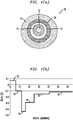
- FIG. 1 illustrates an exemplary low-loss optical fiber formed in accordance with the present invention, where FIG. 1(a) depicts a cross-sectional view of the view and FIG. 1(b) is a plot of the refractive index profile of this fiber.
- low-loss optical fiber 10 is shown as comprising a central core region 12 that is Cl-doped in order to improve viscosity matching with a surrounding F-doped cladding region 14.
- annular stress accommodation region 16 is formed between core region 12 and cladding region 14, where annular stress accommodation region 16 is slightly F-doped; that is, doped with an amount of fluorine dopant sufficient to maintain the viscosity matching with core region 12, but less than what is required to provide the refractive index difference necessary to maintain optical mode confinement within core region 12.
- Cladding region 14 is heavily doped with fluorine, as indicated by the refractive index values shown in FIG. 1 , in order to create an isolation "trench" that assists in confining the propagating optical signal within core region 12 and adjacent annular stress accommodation region 16. While the exemplary embodiment as depicted in FIG. 1 includes both an inner trench 14 and outer trench 18, it is to be understood that an optical fiber formed in accordance with the present invention may comprise only a single heavily F-doped region of width approximately equal to the combination of regions 14 and 18 (with an index value falling between that of regions 14 and 18).
- An outer (moderately F-doped) cladding region 20 and protective polymer coating 22 complete the structure of low-loss fiber 10, as shown in FIG. 1 , where these regions exhibit conventional refractive index values. While FIG. 1(b) shows that the protective polymer coating 22 has a refractive index lower than silica, other polymer coatings - perhaps with a higher refractive index than silica - can also be used.
- Cl-doped core glass compositions are proposed that are thermo-elastically compatible with the conventional F-doped cladding material used with pure silica core optical fibers.
- This compatibility allows for high speed draw processes to be used (e.g., draw rates of 3m/s or higher) when creating the fiber from an optical preform, while preserving the desirable low loss property of the core region.
- this goal is accomplished without introducing defects in the glass materials, since various intentionally-introduced defects are known to contribute to higher losses, as well as hydrogen-induced losses and/or radiation-induced losses in the fabricated optical fiber.
- core region 12 is made of silica containing a high concentration of Si-Cl bonding or SiCl 4 dopant.
- thermo-elastic compatibility between core region 12 and cladding region 14 permits the use of relatively high draw rates (e.g., in excess of 3m/s) without incurring significant draw-induced tension, and also without creating significant refractive index suppression within core region 12.
- the use of a Ge-free core significantly reduces the Rayleigh scattering loss in the core, resulting in optical signal attenuation of less than 0.18 dB/km at a wavelength of 1550 nm, also with little or no hydrogen-induced loss.
- the utilization of a Cl-doped core region in the inventive optical fiber permits the use of relatively low draw temperatures, for example, temperatures in the range of 1800-2200°C. These low draw temperatures decrease the glass fictive temperature (T f ), for example to a value of about 1600°C, which lowers the attenuation in the fiber.
- T f glass fictive temperature
- T f fictive temperature
- the glass compositions (as well as dopant concentrations) vary radially in forming a waveguide structure.
- Different dopant types and concentrations affect the rates of glass structural relaxation, resulting in different T f values at different radial positions in an optical fiber.
- significant T f changes occur in the core and adjacent cladding regions - the very areas within which most of the optical power propagates. It is known in the prior art that changes in T f result in changes in both the refractive indicies and glass densities. Therefore, it is desirable to minimize changes in such properties within the waveguiding regions to reduce fiber attention.
- one factor to consider is the desire to match the material properties, e.g., viscosity, density and thermal expansion coefficients (CTE) of the materials comprising the core and cladding regions in a manner that minimizes draw-induced stresses, while also reducing stress gradients over a wide range of draw conditions.
- material properties e.g., viscosity, density and thermal expansion coefficients (CTE)
- FIG. 2 is a density plot of both Cl-doped silica and F-doped silica, measured at the fictive temperature T f of 1600°C, and plotted as a function of chlorine concentration [Cl] and fluorine concentration [F], respectively.
- This plot is based on experimental data published by Kakiuchida et al. in the article " Refractive index and density in F- and Cl-doped silica glasses", published in Applied Physics Letters, Vol. 86, beginning at page 161907 (2005 ).
- region A of the density plots of FIG. 2 it is possible to control the concentrations of both dopants so that their densities are matched at the fictive temperature of 1600°C.
- FIG. 3 contains graphs of (dn/dT f ) and (dp/dT f ) for both Cl-doped silica and F-doped silica as a function of [Cl] and [F], respectively.
- annular stress accommodation region 16 is formed of F-doped silica having a value of [F] in the range of 1.5 mol% (i.e., a moderately-doped value), thus providing the desired visco-elastic properties of matched core/cladding density and CTE.
- annular stress accommodation region 16 provides the necessary compensation for the remaining mis-match between the viscosity of core region 12 and cladding layer 14, with the density d ⁇ /dT f , and refractive index dn/dT f of annular stress accommodation region 16 closely matching those of core region 12.
- Outer cladding region(s) 14/18 is(are) more heavily doped, forming the desired index trench that provides the required optical mode confinement, as shown in the index profile of FIG. 1(b) .
- the drawn fiber is found to exhibit low residual stress (as well as low stress gradients) within the combined areas of core region 12 and annular region 16.
- an average residual stress of less than about 100 MPa is provided by the inclusion of stress-accommodation region 16.
- Approximately 98% of the energy of the propagating optical signal resides in these two regions.
- Table I shows the power distribution within the core, stress accommodation and cladding regions of an exemplary optical fiber formed in accordance with the present invention. As shown, less than two percent of the optical power propagates in the heavily F-doped cladding regions outside of the stress accommodation region of the inventive design. Table I also shows examples of the prior art, low-loss designs, where about 10% or more of the optical power propagates in the heavily F-doped regions outside of the core.
- FIG. 4 contains plots of refractive index (left vertical axis) and residual stress (right vertical axis) for a low-loss, Cl-doped fiber formed in accordance with the present invention. As formed, this fiber exhibited a loss of 0.174 dB/km for an optical signal propagating at a wavelength of 1557 nm. This loss value is considered to be well within the range defined as "low loss" for most applications.
- the core region was formed to include both Cl and F doping, with the relative ratios in index contributions from SiCl 4 and SiF 4 being about -3.0. That is, an addition of about 10,000 ppm by weight of Cl provides a refractive index of about 0.0013 ⁇ n above undoped silica.
- Addition of about 1mol% F as a co-dopant reduces the refractive index value to about 0.0014 ⁇ n below undoped silica.
- the fiber was drawn at a speed of 10 m/s, with an applied tension of 100 gm (a stress of about 80 MPa in a 125 ⁇ m diameter fiber).
- a relatively low draw temperature of 2125°C was used in the draw process. It is contemplated that a draw speed in the range of about 3 - 30 m/s may be used in the formation of this fiber, with a draw tension in the range of about 25 - 180 gm (a stress between about 20 MPa and 145 MPa in a 125 ⁇ m fiber).
- the refractive index plot shown in FIG. 4 shows raised-index core region 12, formed to include both Cl and F dopants.
- the next region shown in the profile corresponds to annular region 16, which is F-doped to a level that maintains viscosity matching with Cl-doped core region 12.
- Highly-doped (F-doped) cladding region 14 is identified by the "trench", and provides the reduction in refractive index value necessary to provide optical signal confinement in core region 12.
- the residual stress present in the drawn fiber is plotted on the same radial axis, where a positive axial stress indicates tensile residual stress and a negative axial stress indicates compressive residual stress.
- the average residual stress magnitude is about 35 MPa in core region 12, with a maximum stress of about 75 MPa.
- the stress gradient comprises a relatively gradual slope at the interface with trench region 14.
- An advantage of the fiber composition of the present invention is its ability to maintain a low loss characteristic when configured as large effective area fiber, one particular type of long-haul transmission fiber that finds an increasing number of uses.
- fiber-based optical amplifiers and high power applications often utilize fibers with a relatively large effective area.
- utilizing fibers in the transmission span with low loss and large effective area can help to increase transmission capacity and system reach.
- FIG. 5 contains refractive index and stress provides for an exemplary large effective area fiber formed in accordance with the present invention.
- the large effective area, low-loss, Cl-doped fiber was drawn from an optical preform at a speed of 5 m/s with a tension of 35 gm (about 28 MPa in a 125 ⁇ m fiber).
- This particular large effective area transmission fiber is fabricated to exhibit core and adjacent annular stress accommodation regions that are relatively large (in this case, with a core diameter on the order of 16 ⁇ m and stress accommodation region diameter on the order of 20 ⁇ m).
- the residual stress profile for this fiber is shown in Plot A (associated with the left vertical axis) of FIG. 5 .
- FIG. 6 is a graph of the spectral loss associated with the fiber whose characteristics were discussed above and are illustrated in FIG. 4 .
- the spectral data is plotted as a function of 1/ ⁇ 4 , since the Rayleigh scattering has this wavelength dependence.
- c the speed of light in vacuum
- n g the group refractive index of the optical fiber.
- co-doping of Cl and F in the core region of a low-loss optical fiber formed in accordance with the present invention results in creating a fiber with a lower refractive index than a pure silica core fiber.
- the lower index in the core results in also lowering the group index value ng so as to reduce the latency of signal transmission when compared with a span comprised of pure silica core fiber.
- FIG. 7 is a refractive index profile of an exemplary low latency fiber of the present invention, fabricated by co-doping the core region with both Cl and F dopants. As shown, the addition of the F dopant reduced the core refractive index to a value of about -0.001 ⁇ n.
- This particular fiber was configured to have an effective area (A eff ) of about 100 ⁇ m 2 and exhibited a relatively low attenuation of 0.174 dB/km at a transmission wavelength of 1550 nm.
- the group refractive index ng of this fiber was found to be about 1.4624 (when measured at the 1550 nm wavelength value), which is about 0.002 lower than the group refractive index values of a pure silica core fiber.
- an optical preform suitable for creating a low-loss optical fiber consists of a Cl-doped silica core region that was formed from porous Ge-free silica soot that was subsequently sintered in an oxygen-free ambient containing SiCl 4 .
- the oxygen-free ambient used in sintering the Ge-free silica soot can also contain He and Cl 2 .
- a typical oxygen-free sintering ambient is made of flowing helium and SiCl 4 at about 2000 sccm total flow rate in which the SiCl 4 partial pressure is between 15% and 40%.
- the porous silica soot contains a large surface area of siloxane (SiOSi) that is highly reactive with SiCl 4 such that a high Cl-concentration is adsorbed on the silica soot surfaces and thus incorporated in silica upon sintering.
- SiOSi siloxane
- SiF 4 may be added to the oxygen-free ambient.
- a partial pressure of SiF 4 less than 10% has been found suitable for providing an acceptable dopant level within the core.
- the SiCl 4 -dopant itself increases the refractive index to a value between 0.0006 ⁇ n and 0.0018 ⁇ n above silica.
- the higher refractive index in SiCl 4 doped silica provides design flexibility for large effective area fiber (see FIG. 5 ) in broadening the low attenuation waveguide region.
- a combination of SiCl 4 and SiF 4 co-dopants can result in a refractive index between -0.0015 ⁇ n and 0.0017 ⁇ n.
- the SiCl 4 -doped silica forms a waveguide core when it is surrounded by F-doped silica cladding that has a refractive index about 0.0015 to 0.010 ⁇ n below silica.
- the chlorine concentrations are between 6000 and 20,000 ppm and the fluorine concentrations are between 0 and 30,000 ppm.
- Low-loss fiber comprising a SiCl 4 -doped silica core in accordance with the present invention can be fabricated by modified chemical vapor deposition (MCVD), vapor axial deposition (VAD), or other preform processing methods.
- MCVD modified chemical vapor deposition
- VAD vapor axial deposition
- the core region can be formed either with or without SiF 4 co-dopant, where this co-dopant is particularly useful in situations where latency is a concern for the reasons discussed above.
- F-doped silica is first deposited onto an F-doped substrate tube to form the outer cladding with a refractive index appropriate for the desired waveguide structure.
- Porous Ge-free silica soot is then deposited on the F-doped cladding.
- the porous soot is then sintered in an oxygen-free ambient containing SiCl 4 (with or without SiF 4 co-dopant, as appropriate).
- the tube containing the sintered core layers is then collapsed to form a solid core rod.
- an appropriate ambient at the tube interior can be chosen to contain oxygen-free SiCl 4 (with or without SiF 4 ) to further increase the dopant concentration.
- oxygen-containing ambient can be deployed without any SiCl 4 .
- an ambient containing O 2 -free SiCl 4 , helium and chlorine can be used during the collapse to reduce the draw-induced attenuation at 630 nm.
- SiF 4 may be introduced during collapse to achieve homogenous viscosity and thermal expansion coefficient across the core, minimizing stress gradients and providing low latency. It is known that oxygen can remove chlorine from silica. Oxygen-containing ambient during collapse can be used to tailor the Cl-concentration and F-concentration profiles to be thermo-elastically compatible with the F-doped cladding, in accordance with the present invention.
- the porous Ge-free soot body is first dehydrated to remove OH that had been introduced by the VAD torches.
- the porous soot body is then sintered in an oxygen-free ambient containing SiCl 4 (again, with or without SiF 4 ).
- the sintered VAD core rod is over-cladded with F-doped jacket layers to form the desired waveguide structure.
- the sintering ambient consists of helium, SiCl 4 and SiF 4 such that the SiCl 4 partial pressure is between 15% and 40% and the SiF 4 partial pressure is between 0% and 10%.
- the formation of an optical fiber preform having viscosity-matched core and cladding regions can be fabricated by using different concentrations of SiCl 4 and SiF 4 dopant that are introduced in different radial positions of the core and also the core/clad interface. This can be achieved by controlling the partial pressures of SiCl 4 and SiF 4 in the sintering ambient at different radial regions.
- the different SiCl 4 and SiF 4 dopant concentrations affect the glass viscosity and, as a result, the as-drawn axial stress profiles at different fiber radial positions. It is known that a lower stress gradient at core/clad interface can reduce fiber attenuation.
- the incorporation of SiCl 4 with or without SiF 4 co-dopant in silica reduces the glass viscosity such that only a small tensile axial stress remains in the as-drawn fiber.
- the low residual tensile stress in the fiber core permits high fiber draw speeds above 3 m/s and limits the draw-induced core index suppression.
- the draw-induced core index reduction is less than 0.0015 ⁇ n relative to the preform index.
- the core index at the splice joint does not increase more than 0.0015 ⁇ n than that about >5 cm from the splice joint.
- SiCl 4 oxygen-free silicon tetrachloride
- Cl 2 molecular chlorine
- the advantage of higher chlorine incorporation will further assist purification by reacting with OH, impurity metalloid and metal oxides forming chlorides. These chlorides have significant volatility. Therefore, the use of oxygen-free SiCl 4 doping enhances the well-developed purification methods of chlorine purification of silica, as well as incorporating higher levels of chlorine within the silica that can be used to advantageously modify refractive index profiles.
- the present invention is considered to disclose an optical fiber composition and structure having viscosities compatible with the use of an F-doped cladding layer that permit the use of preferred high-speed draw processes while preserving the low loss benefits of a pure silica core.
- high speed drawing process may be used without incurring significant residual stress and index suppression in the core region.
- Appropriate choices of Cl and F dopant concentration among the various regions of the fiber are used to achieve matching material properties between the core and adjacent annular region, as desired to maintain minimal residual stress in the core of the drawn fiber.
- an optical fiber comprises a chlorine-doped silica core region; a fluorine-doped cladding region; and a fluorine-doped annular stress-accommodation region disposed between the core region and the cladding region, the fluorine-doped annular stress-accommodation region including a concentration of a fluorine dopant sufficient to exhibit a viscosity similar to the core region, the cladding region exhibiting a fluorine dopant concentration greater than the annular stress accommodation region and at least sufficient to provide confinement of the propagating optical signal to the combination of the core region and the annular stress-accommodation region.
- the core region in the optical fiber of the first aspect, includes a high concentration of Si-Cl bonds to provide a desired concentration of chlorine dopant.
- the core region in the optical fiber of the first or second aspect, includes chlorine dopant provided by SiCl 4 .
- the chlorine dopant concentration in the core region and the fluorine dopant in the annular stress-accommodation are determined such that the density of the core region essentially matches the density of the annular stress-accommodation region at a determined fictive temperature T f .
- the fictive temperature T f is about 1600°C.
- the optical fiber has an attenuation of less than about 0.33 dB/km at a wavelength of about 1385 nm.
- the chlorine dopant concentration in the silica core region is between about 2000 ppm and 15,000 ppm by weight.
- the fluorine dopant concentration in the annular stress-accommodation region is between about 0.3 mol% and 3.0mol%.
- the silica core region is co-doped to include fluorine dopant in addition to the chlorine dopant.
- the optical fiber of the ninth aspect has a group refractive index lower than the group refractive index value of pure silica.
- the silica core region is substantially free of any germanium dopant.
- the chlorine dopant concentration in the core region and the fluorine dopant in the annular stress-accommodation are determined such that the fraction of optical power present in the cladding region is less than 2%.
- the optical fiber of the first to twelfth aspects has an attenuation of less than about 0.175 dB/km at a propagating signal wavelength of about 1550 nm.
- the optical fiber in the optical fiber of one of the first to thirteenth aspects, has an effective area of more than about 100 ⁇ m 2 at a wavelength of about 1550 nm.
- the average residual stress is less than about 100 MPa in the core region and the annular stress-accommodation region.
- a method of fabricating an optical fiber from an optical fiber preform comprises the steps of: providing an optical fiber preform having a chlorine-doped silica core region, a fluorine-doped cladding region and an annular stress-accommodation region disposed between the core region and the cladding region, the annular stress-accommodation region including a concentration of a fluorine dopant sufficient to exhibit a viscosity similar to the core region, and the cladding region exhibiting a fluorine dopant concentration greater than the annular stress region; heating the provided preform to a predetermined draw temperature; and pulling the heated preform with a determined draw tension and a determined draw rate so as to draw down the optical preform into a desired final dimension of an optical fiber.
- the draw temperature is determined from the selected viscosity of the core and annular stress-accommodation regions. In an eighteenth aspect, in the of the seventeenth aspect, the draw temperature is in the range of 1800 - 2200 °C. In a nineteenth aspect, in the method of the sixteenth to eighteenth aspects, the draw rate is greater than 3m/s. In a twentieth aspect, in the method of the sixteenth to nineteenth aspects, the draw rate is in the range of 3 - 40 m/s. In a twenty-first aspect, in the method of the sixteenth to twentieth aspects, the draw tension is in the range of 25-250 gm, equivalent to a stress of between about 20 and 200 MPa in a 125 ⁇ m diameter optical fiber.
Landscapes
- Chemical & Material Sciences (AREA)
- Engineering & Computer Science (AREA)
- Physics & Mathematics (AREA)
- Materials Engineering (AREA)
- Organic Chemistry (AREA)
- Geochemistry & Mineralogy (AREA)
- Life Sciences & Earth Sciences (AREA)
- General Life Sciences & Earth Sciences (AREA)
- Manufacturing & Machinery (AREA)
- Chemical Kinetics & Catalysis (AREA)
- General Chemical & Material Sciences (AREA)
- Optics & Photonics (AREA)
- Thermal Sciences (AREA)
- General Physics & Mathematics (AREA)
- Glass Compositions (AREA)
- Optical Fibers, Optical Fiber Cores, And Optical Fiber Bundles (AREA)
- Manufacture, Treatment Of Glass Fibers (AREA)
Applications Claiming Priority (3)
| Application Number | Priority Date | Filing Date | Title |
|---|---|---|---|
| US201462066520P | 2014-10-21 | 2014-10-21 | |
| US201462072606P | 2014-10-30 | 2014-10-30 | |
| US14/825,297 US9658395B2 (en) | 2014-10-21 | 2015-08-13 | Low loss optical fiber and method of making the same |
Publications (3)
| Publication Number | Publication Date |
|---|---|
| EP3012235A2 true EP3012235A2 (fr) | 2016-04-27 |
| EP3012235A3 EP3012235A3 (fr) | 2016-06-15 |
| EP3012235B1 EP3012235B1 (fr) | 2019-12-18 |
Family
ID=54345422
Family Applications (1)
| Application Number | Title | Priority Date | Filing Date |
|---|---|---|---|
| EP15190631.0A Active EP3012235B1 (fr) | 2014-10-21 | 2015-10-20 | Fibre optique à faible perte et son procédé de fabrication |
Country Status (4)
| Country | Link |
|---|---|
| US (2) | US9658395B2 (fr) |
| EP (1) | EP3012235B1 (fr) |
| JP (1) | JP6282622B2 (fr) |
| CN (1) | CN105527675B (fr) |
Cited By (4)
| Publication number | Priority date | Publication date | Assignee | Title |
|---|---|---|---|---|
| WO2017112447A1 (fr) * | 2015-12-22 | 2017-06-29 | Corning Incorporated | Fibre optique en verre de silice dopé au brome et son procédé de production |
| WO2018022411A1 (fr) * | 2016-07-29 | 2018-02-01 | Corning Incorporated | Fibre monomodale à faible perte avec coeur dopé au chlore |
| EP3627197A4 (fr) * | 2017-07-03 | 2021-03-03 | Nippon Telegraph and Telephone Corporation | Fibre optique et système de transmission optique |
| CN115136047A (zh) * | 2020-02-21 | 2022-09-30 | 住友电气工业株式会社 | 光纤 |
Families Citing this family (33)
| Publication number | Priority date | Publication date | Assignee | Title |
|---|---|---|---|---|
| JP6268758B2 (ja) * | 2013-06-10 | 2018-01-31 | 住友電気工業株式会社 | 光ファイバ |
| US9874686B2 (en) * | 2015-05-29 | 2018-01-23 | Corning Incorporated | Optical fiber with macrobend loss mitigating layer |
| US20170097465A1 (en) * | 2015-06-30 | 2017-04-06 | Corning Incorporated | Optical fiber with large effective area and low bending loss |
| JP2017024917A (ja) * | 2015-07-15 | 2017-02-02 | 株式会社フジクラ | 光ファイバプリフォーム、光ファイバおよび光ファイバの製造方法 |
| US9919955B2 (en) * | 2015-07-24 | 2018-03-20 | Ofs Fitel, Llc | Optical fiber with low loss and nanoscale structurally homogeneous core |
| JP2018008850A (ja) * | 2016-07-14 | 2018-01-18 | 住友電気工業株式会社 | マルチコア光ファイバ製造方法 |
| JP6951852B2 (ja) | 2017-03-27 | 2021-10-20 | 古河電気工業株式会社 | 光ファイバ及び光ファイバの製造方法 |
| CN107132613A (zh) * | 2017-06-08 | 2017-09-05 | 中国电子科技集团公司电子科学研究院 | 一种泄漏通道型光纤及其生产方法 |
| CN109081575A (zh) * | 2017-06-14 | 2018-12-25 | 中天科技精密材料有限公司 | 光纤预制棒及其制造方法 |
| CN109081576B (zh) * | 2017-06-14 | 2021-05-14 | 中天科技精密材料有限公司 | 光纤预制棒及其制造方法 |
| US10947149B2 (en) * | 2017-10-30 | 2021-03-16 | Corning Incorporated | Halogen-doped silica for optical fiber preforms |
| KR102776021B1 (ko) * | 2018-03-07 | 2025-03-04 | 스미토모 덴키 고교 가부시키가이샤 | 광 파이버 |
| WO2019173916A1 (fr) * | 2018-03-14 | 2019-09-19 | Accutech Medical Technologies Inc. | Fibre optique chirurgicale et son procédé de fabrication |
| JP2020140080A (ja) * | 2019-02-28 | 2020-09-03 | 住友電気工業株式会社 | 光ファイバ |
| EP3955034B1 (fr) * | 2019-04-10 | 2024-07-17 | Sumitomo Electric Industries, Ltd. | Fibre optique |
| CN110357410B (zh) * | 2019-06-12 | 2020-08-04 | 烽火通信科技股份有限公司 | 用于制造超低衰减光纤的光纤预制棒、方法及光纤 |
| JP7326906B2 (ja) * | 2019-06-18 | 2023-08-16 | 住友電気工業株式会社 | 光ファイバ |
| CN112305665A (zh) * | 2019-08-02 | 2021-02-02 | 斯特里特技术有限公司 | 具有较大有效面积的截流移位光纤 |
| CN112441736B (zh) * | 2019-08-30 | 2023-10-03 | 中天科技精密材料有限公司 | 光纤预制棒及其制备方法、等离子沉积设备 |
| US20230016133A1 (en) * | 2019-12-13 | 2023-01-19 | Sumitomo Electric Industries, Ltd. | Optical fiber |
| CN110954985B (zh) * | 2019-12-26 | 2022-03-25 | 长飞光纤光缆股份有限公司 | 一种超低衰减大有效面积单模光纤 |
| CN115190871A (zh) | 2020-01-17 | 2022-10-14 | 康宁股份有限公司 | 具有低损耗和微弯曲敏感度的涂层直径减小的氯掺杂二氧化硅光纤 |
| JP2021139963A (ja) * | 2020-03-02 | 2021-09-16 | 古河電気工業株式会社 | 光結合器及び光出力装置 |
| EP4130819A4 (fr) | 2020-03-27 | 2024-03-20 | Furukawa Electric Co., Ltd. | Fibre optique |
| CN111458789B (zh) * | 2020-04-26 | 2021-11-09 | 中天科技光纤有限公司 | 光纤 |
| CN112649916B (zh) * | 2020-12-25 | 2022-06-28 | 长飞光纤光缆股份有限公司 | 一种小型化器件用色散补偿光纤及模块 |
| JP7717474B2 (ja) * | 2021-03-11 | 2025-08-04 | 古河電気工業株式会社 | マルチコアファイバ、マルチコアファイバの製造方法、マルチコアファイバ母材、およびマルチコアファイバ母材の製造方法 |
| JP7704554B2 (ja) * | 2021-03-29 | 2025-07-08 | 古河電気工業株式会社 | 光ファイバ |
| US20230167002A1 (en) * | 2021-11-30 | 2023-06-01 | Corning Incorporated | Optical fibers and method of making the same |
| CN115201961A (zh) * | 2022-06-14 | 2022-10-18 | 江苏亨通光导新材料有限公司 | 一种陆地用g.654.e光纤及其制作工艺 |
| CN116449481A (zh) * | 2023-03-29 | 2023-07-18 | 中国科学院上海光学精密机械研究所 | 稀土掺杂大模场磷酸盐光纤 |
| WO2025019512A1 (fr) * | 2023-07-20 | 2025-01-23 | Ofs Fitel, Llc | Réduction de la sensibilité thermique dans des fibres optiques actives |
| WO2025143138A1 (fr) * | 2023-12-28 | 2025-07-03 | 住友電気工業株式会社 | Fibre optique |
Citations (3)
| Publication number | Priority date | Publication date | Assignee | Title |
|---|---|---|---|---|
| US6917740B2 (en) | 2003-05-30 | 2005-07-12 | Corning Incorporated | Optical fiber having reduced viscosity mismatch |
| US7593612B2 (en) | 2006-10-19 | 2009-09-22 | The Furukawa Electric Co., Ltd. | Optical fiber |
| US7752870B1 (en) | 2003-10-16 | 2010-07-13 | Baker Hughes Incorporated | Hydrogen resistant optical fiber formation technique |
Family Cites Families (20)
| Publication number | Priority date | Publication date | Assignee | Title |
|---|---|---|---|---|
| US4282196A (en) | 1979-10-12 | 1981-08-04 | Bell Telephone Laboratories, Incorporated | Method of preparing optical fibers of silica |
| IT1184068B (it) | 1985-04-10 | 1987-10-22 | Cselt Centro Studi Lab Telecom | Procedimento per la produzione di fibre ottiche in silice drogata con allumina utilizzante reagenti metallorganici |
| JPH0820574B2 (ja) * | 1987-03-06 | 1996-03-04 | 住友電気工業株式会社 | 分散シフトフアイバ及びその製造方法 |
| FR2650584B1 (fr) * | 1989-08-02 | 1993-12-17 | Cie Generale D Electricite | Procede de fabrication d'une fibre optique a gaine dopee |
| WO2000042458A1 (fr) * | 1999-01-18 | 2000-07-20 | Sumitomo Electric Industries, Ltd. | Fibre optique et son procede de fabrication |
| JP2003531796A (ja) * | 2000-03-25 | 2003-10-28 | ヘライオステネフォーアーゲー | サブストレート管及び光ファイバーのプリフォームを製造する方法 |
| CA2355819A1 (fr) * | 2000-08-28 | 2002-02-28 | Sumitomo Electric Industries, Ltd. | Fibre optique, methode de fabrication d'une preforme, et methode de fabrication de la fibre optique |
| AU773229B2 (en) * | 2000-08-28 | 2004-05-20 | Sumitomo Electric Industries, Ltd. | Optical fiber and method of making the same |
| US6690868B2 (en) * | 2001-05-30 | 2004-02-10 | 3M Innovative Properties Company | Optical waveguide article including a fluorine-containing zone |
| US6862900B2 (en) | 2001-09-21 | 2005-03-08 | Corning Incorporated | Method and apparatus for reducing stress between depositions within a substrate tube |
| JP2003300744A (ja) | 2002-04-08 | 2003-10-21 | Sumitomo Electric Ind Ltd | 光ファイバの製造方法及び光ファイバ |
| JP4093553B2 (ja) * | 2002-08-07 | 2008-06-04 | 信越化学工業株式会社 | 光ファイバプリフォームとその製造方法、及びこれを線引きして得られる光ファイバ |
| US20070003198A1 (en) * | 2005-06-29 | 2007-01-04 | Lance Gibson | Low loss optical fiber designs and methods for their manufacture |
| FR2893149B1 (fr) | 2005-11-10 | 2008-01-11 | Draka Comteq France | Fibre optique monomode. |
| WO2008013627A2 (fr) * | 2006-06-30 | 2008-01-31 | Corning Incorporated | Fibre optique à faible perte par courbure à enrobage à module élevé |
| JP2011209702A (ja) * | 2010-03-10 | 2011-10-20 | Sumitomo Electric Ind Ltd | マルチコア光ファイバ |
| US7929818B1 (en) | 2010-06-30 | 2011-04-19 | Corning Incorporated | Large effective area fiber with graded index GE-free core |
| JP5974488B2 (ja) | 2011-04-15 | 2016-08-23 | 住友電気工業株式会社 | 光ファイバおよび光ファイバ母材 |
| JP5831189B2 (ja) | 2011-12-09 | 2015-12-09 | 住友電気工業株式会社 | 光ファイバおよび光伝送システム |
| CN104216045A (zh) * | 2014-09-22 | 2014-12-17 | 江苏亨通光电股份有限公司 | 一种光纤及其制作方法 |
-
2015
- 2015-08-13 US US14/825,297 patent/US9658395B2/en active Active
- 2015-10-20 EP EP15190631.0A patent/EP3012235B1/fr active Active
- 2015-10-21 CN CN201510952429.5A patent/CN105527675B/zh active Active
- 2015-10-21 JP JP2015206815A patent/JP6282622B2/ja active Active
- 2015-11-12 US US14/938,914 patent/US10197728B2/en active Active
Patent Citations (3)
| Publication number | Priority date | Publication date | Assignee | Title |
|---|---|---|---|---|
| US6917740B2 (en) | 2003-05-30 | 2005-07-12 | Corning Incorporated | Optical fiber having reduced viscosity mismatch |
| US7752870B1 (en) | 2003-10-16 | 2010-07-13 | Baker Hughes Incorporated | Hydrogen resistant optical fiber formation technique |
| US7593612B2 (en) | 2006-10-19 | 2009-09-22 | The Furukawa Electric Co., Ltd. | Optical fiber |
Non-Patent Citations (2)
| Title |
|---|
| KAKIUCHIDA ET AL.: "Refractive index and density in F- and Cl-doped silica glasses", APPLIED PHYSICS LETTERS, vol. 86, 2005, pages 161907, XP012065103, DOI: doi:10.1063/1.1897062 |
| M. TATEDA ET AL.: "Design of Viscosity-Matched Optical Fibers", IEEE PHOTONICS TECHNOLOGY LETTERS, vol. 4, no. 9, September 1992 (1992-09-01), pages 1023, XP000305549, DOI: doi:10.1109/68.157136 |
Cited By (10)
| Publication number | Priority date | Publication date | Assignee | Title |
|---|---|---|---|---|
| WO2017112447A1 (fr) * | 2015-12-22 | 2017-06-29 | Corning Incorporated | Fibre optique en verre de silice dopé au brome et son procédé de production |
| US10884184B2 (en) | 2015-12-22 | 2021-01-05 | Corning Incorporated | Bromine-doped optical fiber |
| WO2018022411A1 (fr) * | 2016-07-29 | 2018-02-01 | Corning Incorporated | Fibre monomodale à faible perte avec coeur dopé au chlore |
| WO2018022870A3 (fr) * | 2016-07-29 | 2019-04-25 | Corning Incorporated | Fibre monomode à faible perte pourvue d'un coeur dopé au chlore |
| EP3627197A4 (fr) * | 2017-07-03 | 2021-03-03 | Nippon Telegraph and Telephone Corporation | Fibre optique et système de transmission optique |
| US11366266B2 (en) | 2017-07-03 | 2022-06-21 | Nippon Telegraph And Telephone Corporation | Optical fiber and optical transmission system |
| CN115136047A (zh) * | 2020-02-21 | 2022-09-30 | 住友电气工业株式会社 | 光纤 |
| EP4109150A4 (fr) * | 2020-02-21 | 2023-06-28 | Sumitomo Electric Industries, Ltd. | Fibre optique |
| US11971571B2 (en) | 2020-02-21 | 2024-04-30 | Sumitomo Electric Industries, Ltd. | Optical fiber |
| CN115136047B (zh) * | 2020-02-21 | 2025-07-04 | 住友电气工业株式会社 | 光纤 |
Also Published As
| Publication number | Publication date |
|---|---|
| CN105527675A (zh) | 2016-04-27 |
| US10197728B2 (en) | 2019-02-05 |
| EP3012235A3 (fr) | 2016-06-15 |
| EP3012235B1 (fr) | 2019-12-18 |
| US20160170137A1 (en) | 2016-06-16 |
| JP6282622B2 (ja) | 2018-02-21 |
| US9658395B2 (en) | 2017-05-23 |
| US20160109651A1 (en) | 2016-04-21 |
| JP2016081067A (ja) | 2016-05-16 |
| CN105527675B (zh) | 2020-05-15 |
Similar Documents
| Publication | Publication Date | Title |
|---|---|---|
| EP3012235B1 (fr) | Fibre optique à faible perte et son procédé de fabrication | |
| US10150695B2 (en) | Low loss optical fibers with fluorine and chlorine codoped core regions | |
| EP3166899B1 (fr) | Fibre optique à faible atténuation et à teneur en chlore élevée | |
| EP2629126B1 (fr) | Fibres optiques avec pertes réduites | |
| EP2527893B1 (fr) | Fibre optique monomodale | |
| US10259742B2 (en) | Optical fiber with low loss and nanoscale structurally homogeneous core | |
| US6535679B2 (en) | Optical fiber and method of manufacturing the same | |
| US10031282B2 (en) | Optical fiber | |
| CN108469648B (zh) | 一种超低损耗大有效面积单模光纤及其制造方法 | |
| US11175450B2 (en) | Halogen co-doped optical fibers | |
| AU719695B2 (en) | Optical fiber and method of manufacturing the same | |
| CN103323908A (zh) | 一种单模光纤及其制造方法 | |
| WO2015200191A1 (fr) | Fibre à faible atténuation comportant un cœur à viscosité ajustée et une gaine intérieure | |
| EP4597180A1 (fr) | Fibre optique monomode à faible perte | |
| CN111801609A (zh) | 光纤 | |
| CN100458477C (zh) | 光纤、光传送线路 | |
| JP2017024917A (ja) | 光ファイバプリフォーム、光ファイバおよび光ファイバの製造方法 | |
| JP2003040638A (ja) | 光ファイバ母材の製造方法 |
Legal Events
| Date | Code | Title | Description |
|---|---|---|---|
| PUAI | Public reference made under article 153(3) epc to a published international application that has entered the european phase |
Free format text: ORIGINAL CODE: 0009012 |
|
| AK | Designated contracting states |
Kind code of ref document: A2 Designated state(s): AL AT BE BG CH CY CZ DE DK EE ES FI FR GB GR HR HU IE IS IT LI LT LU LV MC MK MT NL NO PL PT RO RS SE SI SK SM TR |
|
| AX | Request for extension of the european patent |
Extension state: BA ME |
|
| PUAL | Search report despatched |
Free format text: ORIGINAL CODE: 0009013 |
|
| RIC1 | Information provided on ipc code assigned before grant |
Ipc: C03B 37/014 20060101ALI20160428BHEP Ipc: C03C 13/04 20060101ALI20160428BHEP Ipc: G02B 6/036 20060101ALI20160428BHEP Ipc: C03B 37/027 20060101AFI20160428BHEP Ipc: C03B 37/018 20060101ALI20160428BHEP |
|
| RIC1 | Information provided on ipc code assigned before grant |
Ipc: C03B 37/027 20060101AFI20160504BHEP Ipc: G02B 6/036 20060101ALI20160504BHEP Ipc: C03C 13/04 20060101ALI20160504BHEP Ipc: C03B 37/018 20060101ALI20160504BHEP Ipc: C03B 37/014 20060101ALI20160504BHEP |
|
| AK | Designated contracting states |
Kind code of ref document: A3 Designated state(s): AL AT BE BG CH CY CZ DE DK EE ES FI FR GB GR HR HU IE IS IT LI LT LU LV MC MK MT NL NO PL PT RO RS SE SI SK SM TR |
|
| AX | Request for extension of the european patent |
Extension state: BA ME |
|
| STAA | Information on the status of an ep patent application or granted ep patent |
Free format text: STATUS: REQUEST FOR EXAMINATION WAS MADE |
|
| 17P | Request for examination filed |
Effective date: 20161122 |
|
| RBV | Designated contracting states (corrected) |
Designated state(s): AL AT BE BG CH CY CZ DE DK EE ES FI FR GB GR HR HU IE IS IT LI LT LU LV MC MK MT NL NO PL PT RO RS SE SI SK SM TR |
|
| STAA | Information on the status of an ep patent application or granted ep patent |
Free format text: STATUS: EXAMINATION IS IN PROGRESS |
|
| 17Q | First examination report despatched |
Effective date: 20171116 |
|
| GRAP | Despatch of communication of intention to grant a patent |
Free format text: ORIGINAL CODE: EPIDOSNIGR1 |
|
| STAA | Information on the status of an ep patent application or granted ep patent |
Free format text: STATUS: GRANT OF PATENT IS INTENDED |
|
| RIC1 | Information provided on ipc code assigned before grant |
Ipc: G02B 6/036 20060101ALI20190625BHEP Ipc: C03B 37/014 20060101ALI20190625BHEP Ipc: G02B 6/02 20060101ALI20190625BHEP Ipc: C03B 37/018 20060101ALI20190625BHEP Ipc: C03B 37/027 20060101AFI20190625BHEP Ipc: C03C 13/04 20060101ALI20190625BHEP |
|
| INTG | Intention to grant announced |
Effective date: 20190712 |
|
| GRAS | Grant fee paid |
Free format text: ORIGINAL CODE: EPIDOSNIGR3 |
|
| GRAA | (expected) grant |
Free format text: ORIGINAL CODE: 0009210 |
|
| STAA | Information on the status of an ep patent application or granted ep patent |
Free format text: STATUS: THE PATENT HAS BEEN GRANTED |
|
| AK | Designated contracting states |
Kind code of ref document: B1 Designated state(s): AL AT BE BG CH CY CZ DE DK EE ES FI FR GB GR HR HU IE IS IT LI LT LU LV MC MK MT NL NO PL PT RO RS SE SI SK SM TR |
|
| REG | Reference to a national code |
Ref country code: CH Ref legal event code: EP |
|
| REG | Reference to a national code |
Ref country code: IE Ref legal event code: FG4D |
|
| REG | Reference to a national code |
Ref country code: DE Ref legal event code: R096 Ref document number: 602015043768 Country of ref document: DE |
|
| REG | Reference to a national code |
Ref country code: AT Ref legal event code: REF Ref document number: 1214423 Country of ref document: AT Kind code of ref document: T Effective date: 20200115 |
|
| REG | Reference to a national code |
Ref country code: NL Ref legal event code: MP Effective date: 20191218 |
|
| PG25 | Lapsed in a contracting state [announced via postgrant information from national office to epo] |
Ref country code: NO Free format text: LAPSE BECAUSE OF FAILURE TO SUBMIT A TRANSLATION OF THE DESCRIPTION OR TO PAY THE FEE WITHIN THE PRESCRIBED TIME-LIMIT Effective date: 20200318 Ref country code: GR Free format text: LAPSE BECAUSE OF FAILURE TO SUBMIT A TRANSLATION OF THE DESCRIPTION OR TO PAY THE FEE WITHIN THE PRESCRIBED TIME-LIMIT Effective date: 20200319 Ref country code: LT Free format text: LAPSE BECAUSE OF FAILURE TO SUBMIT A TRANSLATION OF THE DESCRIPTION OR TO PAY THE FEE WITHIN THE PRESCRIBED TIME-LIMIT Effective date: 20191218 Ref country code: LV Free format text: LAPSE BECAUSE OF FAILURE TO SUBMIT A TRANSLATION OF THE DESCRIPTION OR TO PAY THE FEE WITHIN THE PRESCRIBED TIME-LIMIT Effective date: 20191218 Ref country code: SE Free format text: LAPSE BECAUSE OF FAILURE TO SUBMIT A TRANSLATION OF THE DESCRIPTION OR TO PAY THE FEE WITHIN THE PRESCRIBED TIME-LIMIT Effective date: 20191218 Ref country code: BG Free format text: LAPSE BECAUSE OF FAILURE TO SUBMIT A TRANSLATION OF THE DESCRIPTION OR TO PAY THE FEE WITHIN THE PRESCRIBED TIME-LIMIT Effective date: 20200318 Ref country code: FI Free format text: LAPSE BECAUSE OF FAILURE TO SUBMIT A TRANSLATION OF THE DESCRIPTION OR TO PAY THE FEE WITHIN THE PRESCRIBED TIME-LIMIT Effective date: 20191218 |
|
| REG | Reference to a national code |
Ref country code: LT Ref legal event code: MG4D |
|
| PG25 | Lapsed in a contracting state [announced via postgrant information from national office to epo] |
Ref country code: RS Free format text: LAPSE BECAUSE OF FAILURE TO SUBMIT A TRANSLATION OF THE DESCRIPTION OR TO PAY THE FEE WITHIN THE PRESCRIBED TIME-LIMIT Effective date: 20191218 Ref country code: HR Free format text: LAPSE BECAUSE OF FAILURE TO SUBMIT A TRANSLATION OF THE DESCRIPTION OR TO PAY THE FEE WITHIN THE PRESCRIBED TIME-LIMIT Effective date: 20191218 |
|
| PG25 | Lapsed in a contracting state [announced via postgrant information from national office to epo] |
Ref country code: AL Free format text: LAPSE BECAUSE OF FAILURE TO SUBMIT A TRANSLATION OF THE DESCRIPTION OR TO PAY THE FEE WITHIN THE PRESCRIBED TIME-LIMIT Effective date: 20191218 |
|
| PG25 | Lapsed in a contracting state [announced via postgrant information from national office to epo] |
Ref country code: EE Free format text: LAPSE BECAUSE OF FAILURE TO SUBMIT A TRANSLATION OF THE DESCRIPTION OR TO PAY THE FEE WITHIN THE PRESCRIBED TIME-LIMIT Effective date: 20191218 Ref country code: PT Free format text: LAPSE BECAUSE OF FAILURE TO SUBMIT A TRANSLATION OF THE DESCRIPTION OR TO PAY THE FEE WITHIN THE PRESCRIBED TIME-LIMIT Effective date: 20200513 Ref country code: RO Free format text: LAPSE BECAUSE OF FAILURE TO SUBMIT A TRANSLATION OF THE DESCRIPTION OR TO PAY THE FEE WITHIN THE PRESCRIBED TIME-LIMIT Effective date: 20191218 Ref country code: NL Free format text: LAPSE BECAUSE OF FAILURE TO SUBMIT A TRANSLATION OF THE DESCRIPTION OR TO PAY THE FEE WITHIN THE PRESCRIBED TIME-LIMIT Effective date: 20191218 Ref country code: CZ Free format text: LAPSE BECAUSE OF FAILURE TO SUBMIT A TRANSLATION OF THE DESCRIPTION OR TO PAY THE FEE WITHIN THE PRESCRIBED TIME-LIMIT Effective date: 20191218 |
|
| PG25 | Lapsed in a contracting state [announced via postgrant information from national office to epo] |
Ref country code: SM Free format text: LAPSE BECAUSE OF FAILURE TO SUBMIT A TRANSLATION OF THE DESCRIPTION OR TO PAY THE FEE WITHIN THE PRESCRIBED TIME-LIMIT Effective date: 20191218 Ref country code: SK Free format text: LAPSE BECAUSE OF FAILURE TO SUBMIT A TRANSLATION OF THE DESCRIPTION OR TO PAY THE FEE WITHIN THE PRESCRIBED TIME-LIMIT Effective date: 20191218 Ref country code: IS Free format text: LAPSE BECAUSE OF FAILURE TO SUBMIT A TRANSLATION OF THE DESCRIPTION OR TO PAY THE FEE WITHIN THE PRESCRIBED TIME-LIMIT Effective date: 20200418 |
|
| REG | Reference to a national code |
Ref country code: DE Ref legal event code: R097 Ref document number: 602015043768 Country of ref document: DE |
|
| REG | Reference to a national code |
Ref country code: AT Ref legal event code: MK05 Ref document number: 1214423 Country of ref document: AT Kind code of ref document: T Effective date: 20191218 |
|
| PLBE | No opposition filed within time limit |
Free format text: ORIGINAL CODE: 0009261 |
|
| STAA | Information on the status of an ep patent application or granted ep patent |
Free format text: STATUS: NO OPPOSITION FILED WITHIN TIME LIMIT |
|
| PG25 | Lapsed in a contracting state [announced via postgrant information from national office to epo] |
Ref country code: DK Free format text: LAPSE BECAUSE OF FAILURE TO SUBMIT A TRANSLATION OF THE DESCRIPTION OR TO PAY THE FEE WITHIN THE PRESCRIBED TIME-LIMIT Effective date: 20191218 Ref country code: ES Free format text: LAPSE BECAUSE OF FAILURE TO SUBMIT A TRANSLATION OF THE DESCRIPTION OR TO PAY THE FEE WITHIN THE PRESCRIBED TIME-LIMIT Effective date: 20191218 |
|
| 26N | No opposition filed |
Effective date: 20200921 |
|
| PG25 | Lapsed in a contracting state [announced via postgrant information from national office to epo] |
Ref country code: SI Free format text: LAPSE BECAUSE OF FAILURE TO SUBMIT A TRANSLATION OF THE DESCRIPTION OR TO PAY THE FEE WITHIN THE PRESCRIBED TIME-LIMIT Effective date: 20191218 Ref country code: AT Free format text: LAPSE BECAUSE OF FAILURE TO SUBMIT A TRANSLATION OF THE DESCRIPTION OR TO PAY THE FEE WITHIN THE PRESCRIBED TIME-LIMIT Effective date: 20191218 |
|
| PG25 | Lapsed in a contracting state [announced via postgrant information from national office to epo] |
Ref country code: IT Free format text: LAPSE BECAUSE OF FAILURE TO SUBMIT A TRANSLATION OF THE DESCRIPTION OR TO PAY THE FEE WITHIN THE PRESCRIBED TIME-LIMIT Effective date: 20191218 |
|
| PG25 | Lapsed in a contracting state [announced via postgrant information from national office to epo] |
Ref country code: PL Free format text: LAPSE BECAUSE OF FAILURE TO SUBMIT A TRANSLATION OF THE DESCRIPTION OR TO PAY THE FEE WITHIN THE PRESCRIBED TIME-LIMIT Effective date: 20191218 |
|
| REG | Reference to a national code |
Ref country code: CH Ref legal event code: PL |
|
| PG25 | Lapsed in a contracting state [announced via postgrant information from national office to epo] |
Ref country code: MC Free format text: LAPSE BECAUSE OF FAILURE TO SUBMIT A TRANSLATION OF THE DESCRIPTION OR TO PAY THE FEE WITHIN THE PRESCRIBED TIME-LIMIT Effective date: 20191218 Ref country code: LU Free format text: LAPSE BECAUSE OF NON-PAYMENT OF DUE FEES Effective date: 20201020 |
|
| REG | Reference to a national code |
Ref country code: BE Ref legal event code: MM Effective date: 20201031 |
|
| PG25 | Lapsed in a contracting state [announced via postgrant information from national office to epo] |
Ref country code: CH Free format text: LAPSE BECAUSE OF NON-PAYMENT OF DUE FEES Effective date: 20201031 Ref country code: BE Free format text: LAPSE BECAUSE OF NON-PAYMENT OF DUE FEES Effective date: 20201031 Ref country code: LI Free format text: LAPSE BECAUSE OF NON-PAYMENT OF DUE FEES Effective date: 20201031 |
|
| PG25 | Lapsed in a contracting state [announced via postgrant information from national office to epo] |
Ref country code: IE Free format text: LAPSE BECAUSE OF NON-PAYMENT OF DUE FEES Effective date: 20201020 |
|
| PG25 | Lapsed in a contracting state [announced via postgrant information from national office to epo] |
Ref country code: TR Free format text: LAPSE BECAUSE OF FAILURE TO SUBMIT A TRANSLATION OF THE DESCRIPTION OR TO PAY THE FEE WITHIN THE PRESCRIBED TIME-LIMIT Effective date: 20191218 Ref country code: MT Free format text: LAPSE BECAUSE OF FAILURE TO SUBMIT A TRANSLATION OF THE DESCRIPTION OR TO PAY THE FEE WITHIN THE PRESCRIBED TIME-LIMIT Effective date: 20191218 Ref country code: CY Free format text: LAPSE BECAUSE OF FAILURE TO SUBMIT A TRANSLATION OF THE DESCRIPTION OR TO PAY THE FEE WITHIN THE PRESCRIBED TIME-LIMIT Effective date: 20191218 |
|
| PG25 | Lapsed in a contracting state [announced via postgrant information from national office to epo] |
Ref country code: MK Free format text: LAPSE BECAUSE OF FAILURE TO SUBMIT A TRANSLATION OF THE DESCRIPTION OR TO PAY THE FEE WITHIN THE PRESCRIBED TIME-LIMIT Effective date: 20191218 |
|
| P01 | Opt-out of the competence of the unified patent court (upc) registered |
Effective date: 20230411 |
|
| PGFP | Annual fee paid to national office [announced via postgrant information from national office to epo] |
Ref country code: DE Payment date: 20251128 Year of fee payment: 11 |
|
| PGFP | Annual fee paid to national office [announced via postgrant information from national office to epo] |
Ref country code: GB Payment date: 20251127 Year of fee payment: 11 |
|
| PGFP | Annual fee paid to national office [announced via postgrant information from national office to epo] |
Ref country code: FR Payment date: 20251125 Year of fee payment: 11 |