EP3013123A1 - Système d'éclairage et procédé de commande correspondant - Google Patents
Système d'éclairage et procédé de commande correspondant Download PDFInfo
- Publication number
- EP3013123A1 EP3013123A1 EP14189719.9A EP14189719A EP3013123A1 EP 3013123 A1 EP3013123 A1 EP 3013123A1 EP 14189719 A EP14189719 A EP 14189719A EP 3013123 A1 EP3013123 A1 EP 3013123A1
- Authority
- EP
- European Patent Office
- Prior art keywords
- lamp
- luminaire
- brightness
- control module
- module
- Prior art date
- Legal status (The legal status is an assumption and is not a legal conclusion. Google has not performed a legal analysis and makes no representation as to the accuracy of the status listed.)
- Granted
Links
Images


Classifications
-
- H—ELECTRICITY
- H05—ELECTRIC TECHNIQUES NOT OTHERWISE PROVIDED FOR
- H05B—ELECTRIC HEATING; ELECTRIC LIGHT SOURCES NOT OTHERWISE PROVIDED FOR; CIRCUIT ARRANGEMENTS FOR ELECTRIC LIGHT SOURCES, IN GENERAL
- H05B31/00—Electric arc lamps
- H05B31/48—Electric arc lamps having more than two electrodes
- H05B31/50—Electric arc lamps having more than two electrodes specially adapted for AC
-
- H—ELECTRICITY
- H05—ELECTRIC TECHNIQUES NOT OTHERWISE PROVIDED FOR
- H05B—ELECTRIC HEATING; ELECTRIC LIGHT SOURCES NOT OTHERWISE PROVIDED FOR; CIRCUIT ARRANGEMENTS FOR ELECTRIC LIGHT SOURCES, IN GENERAL
- H05B47/00—Circuit arrangements for operating light sources in general, i.e. where the type of light source is not relevant
- H05B47/10—Controlling the light source
- H05B47/105—Controlling the light source in response to determined parameters
- H05B47/115—Controlling the light source in response to determined parameters by determining the presence or movement of objects or living beings
- H05B47/13—Controlling the light source in response to determined parameters by determining the presence or movement of objects or living beings by using passive infrared detectors
-
- H—ELECTRICITY
- H05—ELECTRIC TECHNIQUES NOT OTHERWISE PROVIDED FOR
- H05B—ELECTRIC HEATING; ELECTRIC LIGHT SOURCES NOT OTHERWISE PROVIDED FOR; CIRCUIT ARRANGEMENTS FOR ELECTRIC LIGHT SOURCES, IN GENERAL
- H05B47/00—Circuit arrangements for operating light sources in general, i.e. where the type of light source is not relevant
- H05B47/10—Controlling the light source
- H05B47/105—Controlling the light source in response to determined parameters
- H05B47/115—Controlling the light source in response to determined parameters by determining the presence or movement of objects or living beings
-
- H—ELECTRICITY
- H05—ELECTRIC TECHNIQUES NOT OTHERWISE PROVIDED FOR
- H05B—ELECTRIC HEATING; ELECTRIC LIGHT SOURCES NOT OTHERWISE PROVIDED FOR; CIRCUIT ARRANGEMENTS FOR ELECTRIC LIGHT SOURCES, IN GENERAL
- H05B47/00—Circuit arrangements for operating light sources in general, i.e. where the type of light source is not relevant
- H05B47/10—Controlling the light source
- H05B47/175—Controlling the light source by remote control
- H05B47/19—Controlling the light source by remote control via wireless transmission
- H05B47/195—Controlling the light source by remote control via wireless transmission the transmission using visible or infrared light
-
- H—ELECTRICITY
- H05—ELECTRIC TECHNIQUES NOT OTHERWISE PROVIDED FOR
- H05B—ELECTRIC HEATING; ELECTRIC LIGHT SOURCES NOT OTHERWISE PROVIDED FOR; CIRCUIT ARRANGEMENTS FOR ELECTRIC LIGHT SOURCES, IN GENERAL
- H05B47/00—Circuit arrangements for operating light sources in general, i.e. where the type of light source is not relevant
- H05B47/10—Controlling the light source
- H05B47/175—Controlling the light source by remote control
- H05B47/198—Grouping of control procedures or address assignation to light sources
-
- Y—GENERAL TAGGING OF NEW TECHNOLOGICAL DEVELOPMENTS; GENERAL TAGGING OF CROSS-SECTIONAL TECHNOLOGIES SPANNING OVER SEVERAL SECTIONS OF THE IPC; TECHNICAL SUBJECTS COVERED BY FORMER USPC CROSS-REFERENCE ART COLLECTIONS [XRACs] AND DIGESTS
- Y02—TECHNOLOGIES OR APPLICATIONS FOR MITIGATION OR ADAPTATION AGAINST CLIMATE CHANGE
- Y02B—CLIMATE CHANGE MITIGATION TECHNOLOGIES RELATED TO BUILDINGS, e.g. HOUSING, HOUSE APPLIANCES OR RELATED END-USER APPLICATIONS
- Y02B20/00—Energy efficient lighting technologies, e.g. halogen lamps or gas discharge lamps
- Y02B20/40—Control techniques providing energy savings, e.g. smart controller or presence detection
Definitions
- the present invention relates to a lighting system having a plurality of luminaires, each luminaire having a luminaire control module, a motion detector module and a communication module, wherein the luminaire control module is connected to the motion detector module and the communication module.
- Modern lighting systems do not simply illuminate particular areas of a building or an area located outside a building, but additionally fulfill health and safety aspects, aiming to increase the working atmosphere e.g. to improve in an office, and also to realize a contemporary design. It is also important that lighting systems work as energy-efficiently as possible. For such tasks, so-called intelligent lighting systems are used, which are characterized by the fact that the lights communicate with each other.
- Such a lighting system with several arranged in a building or room lights is already out of the document DE 10 2012 204 579 B4 known.
- the lights on communication devices so that they are at least partially coupled to each other and at least partially communicate with each other.
- Each of the luminaires realizes at least the operating modes "Luminaire is off”, “Luminaire is on with basic lighting” and “Luminaire is on with maximum specified illuminance on”, whereby the operating mode "Luminaire is on with basic lighting” in relation to the brightness between Operating mode "Luminaire is off” and "Luminaire is on with maximum specified illuminance on”.
- each lamp is provided with a communication module having a transmitting and receiving device.
- the transmitting and receiving device includes an optical transmitter and an optical receiver based on visible or invisible light transmission as well as an ultrasonic transmitter and an ultrasonic receiver.
- the luminaire When the luminaire is switched on, it emits both an optical signal and an ultrasound pulse, which are received by all the other luminaires on the system. Because of the difference between the speed of light and the speed of sound, the signals are recorded with a time delay, which depends on the distance of the individual luminaire from the transmitting luminaire. This time delay is converted into a distance information, so that the distance of the lights of the system is known.
- the luminaires switch on with a brightness and type of lighting that depends on the distance determined.
- the known control system is limited to the range of the optical signal, that is to the respective space of a building in which the lights are arranged.
- the system is not very variable with regard to the integration of further luminaires which, for example, have no ultrasound transmitter or receiver.
- the object of the present invention is therefore to provide a lighting system with a plurality of lights, which is even more variable in the arrangement of the lights and easier to use than the known systems and in particular in an extended office situation with a corridor, many rooms, a reception area and can be used effectively with several floors.
- the subsequent integration or redesign of the arrangement of lights should be easy to implement.
- each luminaire is assigned a position specification in the form of an X-coordinate and a Y-coordinate in the two-dimensional coordinate system.
- these coordinates can be individually assigned manually during installation of the lighting system of each luminaire, for example by means of a remote control or by means of a pushbutton. Alternatively, the assignment of the coordinates can also be done automatically, which will be explained in more detail below.
- the light system according to the invention is suitable for the combined operation of any lights, such as floor lamps, table lamps, pendant lights, surface-mounted or wall lights.
- the above-mentioned lighting system has the advantage that it is suitable by the communication via radio not only for large space situations, but also for a closed office area, in which, for example, in adjoining corridor areas as long as lighting should be guaranteed, as is being done in the adjoining rooms.
- any desired number of luminaires arranged as desired can communicate with one another, wherein, however, only a specific number of luminaires in relevant areas is switched on if required by the lighting control.
- the light control module of the illumination system is used to control at least one electronic ballast of the lamp, which is connected to a light source, such as an LED circuit board or a fluorescent tube.
- the luminaire control module processes the signals received by the motion detection module and the communication module and causes the lighting means to be switched on and off or the brightness and possibly also the color of the luminous means to be switched on in the switched-on state.
- the luminaire control module preferably has its own power supply, which is particularly preferably provided with a primary switching regulator.
- the light control module has a relay which separates the electronic ballast in standby from the mains voltage, so that the total energy consumption the lamp in standby is less than 0.5W.
- the relay may be equipped with a leading tungsten contact so that it can withstand the inrush current of the electronic ballast.
- the activation of the at least one electronic ballast is realized within the luminaire via a DALI network.
- the power is supplied via the integrated power supply.
- the motion detection module includes a motion detector, preferably with high-quality PIR (passive infrared receiver), in particular a quad-PIR sensor.
- the lens of the motion detector is preferably designed small and visually appealing.
- the motion detection module has at least one display means, for example at least one LED, e.g. a dual color LED in the colors red / green to give the operator a feedback on the operating state of the motion detector can.
- the communication module includes a radio transmitter and a receiver for radio signals for communication between the lamps, particularly preferred for the SRD 868 MHz band, by which a range of about 50 m in open terrain / space can be realized.
- a proprietary radio module and a proprietary transmission protocol are preferably used.
- the radio antenna is mounted directly in / on the communication module. Alternatively, an external radio antenna can be connected.
- the light control module, the motion detection module and / or the communication module can either be integrated into the light or designed as separate components, which are subsequently attached to the light and can be connected to the components of the lamp. As a result, a retrofit already existing lights is possible.
- each luminaire additionally has a brightness sensor which is connected to the luminaire control module, wherein the luminaire control module additionally controls the brightness of the respective luminaire as a function of the ambient brightness determined by the brightness sensor.
- the system according to the invention additionally takes into account the existing ambient light. With sufficient ambient light, the lights do not turn on when there is a need for light, so only the brightness required in addition to the ambient light is provided by the light. As a result, overall energy savings can also be achieved.
- the luminaire control module is configured to store a first predetermined brightness value with an associated first radius of a detection area and at least one second predetermined brightness value with an associated second radius of a detection area, the luminaire control module determining the brightness of the luminaire depending on the comparison of the luminaire Distance of the respective lamp from another luminaire, in which an activity was detected, with the first radius and with the second radius set such that in the area to be illuminated, the first brightness value or the second brightness value is reached.
- the illumination system according to the invention therefore offers the gradation of the brightness in at least two stages by a predetermined first brightness value and at least one second brightness value.
- the luminaire on which an activity was detected by the motion detection module, is called a master light.
- the luminaire control module of the respective luminaire controls its brightness such that when the luminaire is within a Distance to a so-called master light is smaller than the first radius, the total brightness at the area to be illuminated corresponds to the first predetermined brightness value. Then, when the luminaire is located at a distance from the master lamp that is smaller than the second radius but greater than the first radius, the total brightness at the area to be illuminated is set to the second predetermined brightness value.
- the ambient brightness can be taken into account.
- the distance of the lights to each other is calculated according to the invention from the known X and Y coordinates of the lights.
- the direct proportion of the light of the respective luminaire contains the proportion of the light emitted by the luminaire, which falls directly onto the area to be illuminated.
- the indirect component is that portion of the light which is produced by the lamp and, before it hits the area to be illuminated, is reflected on a wall or the like, that is to say indirectly to the point to be illuminated (e.g.
- both the direct component of the light and the indirect component of the light are to be included in order to perform a lighting task, it is also preferable to specify a ratio which describes the proportion of the direct component of the light and the portion of the indirect component of the respective component Light emitted light to realize the lighting.
- the brightness of the luminaire may be controlled so that the brightness in the area to be illuminated is gives a value that lies between two predefined brightness values, whereby the brightness of the respective luminaire depends directly on the distance from the master luminaire.
- a linear brightness curve is generated in a predetermined area around the master light. For example, lights that are arranged close to the master light shine brighter and farther lights fade darker.
- each luminaire is assigned to at least one group, wherein the luminaire control module additionally controls the brightness and / or the color of the respective luminaire depending on the affiliation of the respective luminaire to a group. Due to the group affiliation, which is stored by a corresponding group parameter in the luminaire control module, the adjustment of the brightness can be linked to predetermined conditions.
- a group may be defined with the group parameter 0, which always illuminates with a low brightness in at least one activity recorded with the motion detector module in the entire area of the system or in several subgroups of lights (e.g., all groups of a floor of a building).
- Such a lighting group is particularly suitable for corridor and reception areas and emergency exits.
- the lights of entire rooms or rows of lights can be assigned to a group and thereby controlled with additional predetermined conditions.
- the group indication of the luminaire with activity is also transmitted to the other luminaires.
- the grouping makes it possible, for example, to relate lighting only to the immediate surroundings of an activity in a single room. For this purpose, the lights are addressed once room-related and therefore respond automatically only on activity in the respective room. As a result, considerable energy savings can be achieved.
- a luminaire of the system according to the invention may also belong to two or more groups, e.g. a first group, which indicates the floor on which the respective lamp is located, and a second group, which includes the respective space of the lamp.
- the group parameter stored in the lamp control module is multi-dimensional.
- the lighting system according to the invention has a positive influence on the working atmosphere in the light-assisted times, especially in open office situations. Small islands of light in otherwise dark surroundings are avoided. Instead, the brightness of the light around the workstation only gradually decreases.
- the workplace-based solutions increase comfort and save energy. Furthermore, strong contrast changes are avoided, which reduces fatigue in a screen activity.
- the position of a luminaire in the two-dimensional coordinate system can be determined automatically by means of an ultrasound module arranged on the luminaire and of the communication module.
- a measurement of all luminaires belonging to the system is carried out by the time difference between the radio signal and the ultrasound signal, in particular when appropriately prompted by a user, for example during installation or configuration of the illumination system.
- the system determines from a master luminaire the coordinates (XY) for each luminaire and assigns them to the luminaire and causes it to be stored in the luminaire control module.
- Each luminaire of the system with ultrasound module can be used as a master luminaire act.
- the luminaire which was first turned on by the respective user, is determined by the system to be the master luminaire.
- the system is automatically adjustable in a delivery mode.
- additional groups can be automatically formed, for example, the lights in a first room of a first group and the lights in a second room of a second group are assigned.
- a luminaire which is moved into the area of a specific group (for example in a room of a building), automatically enters the system and assigns itself to the group without additional programming effort and its associated X or Y coordinates. Coordinates determined.
- luminaires that do not have an ultrasound module can be manually integrated into the system by giving them a corresponding X and Y coordinate manually, e.g. via a key module described below.
- the groups are also set up across rooms, so that for a person moving in a building, the light transitions between different areas can be made slow and pleasing to the eye.
- the light control module stores an individual for the respective group and / or light lag time or hold time, which is waited for finding the completion of an activity on the respective lamp or the associated master light before the respective light is turned off.
- At least one lamp each has a key module which is connected to the lamp control module, wherein by means of the key module, the respective lamp is manually switched on and off and dimmable.
- the key module e.g. has a mounted on a room wall mechanical switch or button can be operated manually.
- At least one luminaire has an infrared module, so that the X and Y coordinates as well as further parameters of the luminaire control module (eg group parameters) and an on and off signal or dimming of the respective luminaire can be controlled by means of a remote control, wherein the remote control designed as an IR remote control and communicates with the light control module via the infrared module.
- the remote control designed as an IR remote control and communicates with the light control module via the infrared module.
- the remote control can be designed, for example, in the form of a card remote control and, for example, have more than 10, preferably more than 20 keys.
- the remote control preferably includes an infrared transmitter for emitting infrared signals to the infrared module.
- the infrared module preferably has an infrared receiver for receiving infrared signals of the remote control and in a particularly preferred embodiment, a dual color LED or other display means for optically outputting a feedback.
- the lighting system can be set up by a configuration tool which works in conjunction with a PC.
- each luminaire comprising a luminaire control module
- Motion detection module and a communication module wherein the light control module is connected to the motion detection module and the communication module and wherein the communication module operates via a radio channel, wherein the light control module of each light after receiving a radio signal of another light, which reports an activity on this other light, the brightness and / or the color of the respective lamp depending on their position and the position of the other, the radio signal emitting light is controlled in a two-dimensional coordinate system.
- the method according to the invention has the advantages and analogous embodiments discussed above with respect to the illumination system.
- a system comprising a light control module, a motion detector module and a communication module for a light, wherein the light control module is connected to the motion detector module and the communication module, characterized in that the communication module operates via a radio channel and that by the light control module Brightness and / or the color of the respective lamp separately depending on the signals of the communication modules of each other lights on the radio channel and the position of the lights in a two-dimensional coordinate system is controllable.
- the system according to the invention has the advantages discussed above for the lighting system. Further, the system may include the above-described brightness sensor, ultrasound module, button module, and / or the infra-red module discussed above. Further, the light control module may include the above-described embodiments.
- the light control module, the motion detector module and the communication module can be realized together in the system according to the invention in a single component or in different components. Further features, advantages and possible applications of the invention will become apparent from the following description of an embodiment of an illumination system according to the invention and the figures. All described and / or illustrated features alone or in any combination form the subject matter of the present invention, also independent of their summary in the claims or their back references.
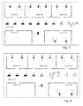
- FIGS. 1 to 6 show, for example, the first floor (Zone 1) of a building with five rooms (Zone1, Z1, Zone1, Z2, Zone1, Z3, Zone1, Z4, Zone1, Z5) and a corridor arranged therebetween.
- the ones in these rooms and in the hall arranged lights are shown as small rectangles in the sketch.
- the first room Zone1, Z1 contains four workplaces, each with a floor lamp f1, f2.
- the lighting group f1, f2 is referred to as zone 1 Z1.
- the floor lamps f6, f7 are arranged in the room with the number Zone1, Z3.
- the room Zone1 Z5 is no workplace and no light available.
- Each luminaire was assigned an X and Y coordinate manually or automatically during the configuration of the lighting system.
- the assignment to the coordinate system is by in the FIGS. 1 to 6 illustrated square grid illustrates.
- a lighting control module 1 which is the central control module for the operation of the lamp. It has its own power supply, which is equipped with a primary switching regulator.
- the power supply is designed for a primary voltage of 100 V to 230 V / 50 Hz to 60 Hz AC.
- the power supply powers all individual components and expansion modules of the system.
- an electronic ballast 2 with which the light control module 1 is connected to be disconnected from the mains voltage, so that the total energy consumption of the lamp in standby is less than 0.5 W.
- the electronic ballast 2 is connected to a lighting means 3, for example an LED printed circuit board or a fluorescent tube.
- a key module 4 which allows the switching on and off and dimming the lamp. Furthermore, the input of parameters such as the working brightness and the basic brightness of a first or second detection area A, B is possible.
- the key module 4 is connected to the light control module 1.
- the light control module 1 is further connected to a motion detection module 5, which transmits signals to the light control module 1 when activity is detected in the area of the respective light by the motion detector, preferably a quad-PIR sensor, of the motion detection module 5.
- the motion detection module 5 may also include a brightness sensor, which measures the brightness of the lighting environment and passes it on to the light control module 1.
- an IR receiver module may be provided, which is provided with an in FIG. 8 illustrated IR remote control 9 communicates. Using the remote control 9 and the IR receiver module, the light can be switched on and off as well as dimmed. In addition, parameters for the respective luminaire can be entered during configuration of the system, for example. For this purpose, the IR receiver module is connected to the light control module 1.
- each luminaire has a radio module 6 with a radio transmitter and receiver, which communicates bidirectionally with the luminaire control module 1 and serves to communicate the luminaires with one another. Signals received by the radio module 6 are forwarded to the light control module 1. In addition, the light control module 1 causes the transmission of radio signals by the radio module 6.
- the radio module 6 operates, for example on the 886.3 MHz SRD band.
- DALI Digital Addressable Lighting Interface
- an unrepresented 1-10 V interface module can be used, which is connected to the electronic ballast 2 via a 1-10 V analog interface.
- an ultrasound module may be provided with an ultrasound transmitter and receiver serving for the above-described automatic assignment of the X, Y coordinates.
- the ultrasound module is also connected to the light control module 1.
- Each luminaire can be operated at a so-called working brightness, which is set by the luminaire control module 1, when an activity is detected at the respective luminaire by a corresponding sensor signal of the motion detector of the motion detection module 5.
- the working brightness can be set during the configuration of the lighting system and, for example, between 80% and 100% of the maximum brightness of the respective lamp.
- each of the lights f1 to f9 and c1 to c10 has a first circular detection area (small circle A), the first radius is stored in the light control module 1 each lamp, in which case if an activity is detected within the first detection area A, a basic brightness is set at the lamp, which is for example 70% of the working brightness.
- the luminaire control module 1 is connected to the luminaire Lamp set a basic brightness, which is for example at 40% of the working brightness.
- the radius and the associated basic brightness of the second detection range B are stored for each luminaire in the respective luminaire control module 1.
- the brightness values for the first detection area and the second detection area B and their radii can be preset individually for each luminaire or for groups of luminaires, for example by inputting by means of a remote control via the infrared module.
- the radii of the second detection areas B are designed such that the second detection areas B of the lights c1, c3, c5, c7 and c9 have a smaller radius (for example, see circle B around the light c7) as the second detection areas B of the lights c2, c4, c6 and c8 (see example circle B around the light c6).
- the second detection range of the luminaires c1, c3, c5, c7 and c9 does not extend to the luminaires in the rooms, while the second detection area of the luminaires c2, c4, c6 and c8 includes at least the closest luminaires in the rooms.
- an activity of the luminaires in the rooms affects the hall luminaires c2, c4, c6 and c8; if applicable, 40% of the working brightness is set in the present example.
- the luminaires in the rooms are too far away from the luminaires c1, c3, c5, c7 and c9, so that an activity on these luminaires does not cause a change in the "off" state (see also the below with reference to FIGS FIGS. 5 and 6 described behavior of the lights c4, c5 and c6 at an activity in the room Zone1, Z2).
- Y coordinates of the lights calculated by determining the distance of the position of the luminaire with the activity to the position of the respective luminaire.
- FIG. 2 shows by way of example in each case the first detection area A and the second detection area B of the lamps f3 and f8, which are located in the respective rooms Zone1, Z2 and Zone1, Z4.
- the luminaire c9 now communicates via radio via the radio module 6 with all the other lights f1 to f9, c1 to c8 and c10 and sends them the message that an activity has been detected in it.
- the coordinates X, Y of the luminaire c9, at which the activity was detected, and their group (Zone1, Z0) are also transmitted.
- the respective lighting control module 1 of the other lights Derived from its spatial coordinate X, Y, the respective lighting control module 1 of the other lights, such as the lights c7 and c8, for example, determine by means of known methods from trigonometry the distance of the luminaire c9 from the luminaire c7 or c8 and from this, whether the luminaire c9 is in the first detection area A of the luminaire c7 or c8, in its second detection area B, or outside of these detection areas. Depending on the result of this comparison, the luminaire control module 1 causes the luminaires to be operated with a predetermined basic brightness.
- luminaire c8 has analogous detection regions to c6 that the luminaire c9 is arranged in the first detection region A of the luminaire c8. Accordingly, c8 is set to a basic brightness adjusted by 70% of the working brightness.
- FIG. 1 It can also be seen that the lamp c9 is within the circle with the radius B of the second detection range of the lamp c7, so that it is set to the basic brightness with the value 40% of the working brightness.
- the respective lighting control module 1 Before setting the respective basic brightness, the respective lighting control module 1 also checks the affiliation of the luminaire c9 to the group of the luminaire c8 or c7 on the basis of the group information communicated by the luminaire c9.
- the basic brightness levels given above are also set. This can be achieved in one embodiment, for example by means of a corresponding pulse width modulation (PWM).
- PWM pulse width modulation
- an activity of the lights f1 to f9 is considered only if they are in the same group, i. is detected in the same room.
- An activity of the lights of the group Z0 is not considered for the lights of the groups Z1 to Z5.
- FIG. 4 is shown turn in a further movement of the person 10 through the hall along the lights c8, c7 and c6 these lights also on working brightness.
- the luminaires c9, c8 and c7 which have passed in each case continue to light up at the level of working brightness in their pre-set follow-up time.
- the lamp c6 in the first detection area A of the lamp c5 this switches to a basic brightness with 70% of the working brightness.
- the lamp c6 is in the second detection range B of the lights c4 and c10, so that the lights c4 and c10 switch to a basic brightness with 40% of the working brightness.
- the lights f1 to f9 and c1 to c3 remain switched off.
- the person moves 10, as in FIG. 6 shown, to the light f3, which then switches to working brightness.
- the lamp f3 is in the second detection range of the lamp f2, but this is not turned on because the lamp f2 does not belong to the group Z2, but to the group Z1.
- the lights f1 to f7 all have an analog size of the detection areas, as they are in FIG. 2 For the lamp f3 is shown.
- the lamp f4 switches to a basic brightness of 70% of the working brightness and the lamps f5 and c4 switch to a basic brightness of 40% of the working brightness.
- the lights f1, f2, f6 to f9, c1 to c3 and c5 to c10 are turned off.
- the luminaire control module 1 can take into account further control parameters such as optional aging compensation of the luminous means and the ambient brightness determined by the brightness sensor when setting the brightness.
- the automatic switching between two brightnesses is done as a dimming process hard-coded within 1 second. Dimming over the entire value range by hand takes hard-coded 5 seconds.
- the aging compensation in particular with regard to the compensation of the decreasing brightness of the LEDs, can for example be implemented in such a way that the maximum brightness is first reduced for a new luminaire, and then gradually increased over the product life cycle.
- the time period in hours and the initial brightness is configurable.
- the previous runtime can also be set manually if, for example, the LED arrays are replaced.
- the various parameters of the control can be set.
- the input of the parameters is preferably password protected.
- the configuration of the swarm function is preferably carried out separately and preferably has its own password.
- a password is entered with P ⁇ rights level> ENTER ⁇ password> ENTER. Different access rights, which have different passwords, are implemented to distinguish the end user from the service technicians.
- P is pressed once. This is done automatically after 5 minutes without user input.
- the parameters can be changed with M ⁇ ParameterlD> ENTER ⁇ Parameter value> ENTER.
- Boolean parameters can be entered with M ⁇ ParameterID> ONIOFF, or alternatively with M ⁇ ParameterID> ENTER 1
- Non-scalar values are entered with M ⁇ ParameterID> ENTER ⁇ Value1> ENTER ⁇ Value2> ENTER.
- the swarm function also offers the option of entering the most important parameters via the shortcut key.
- a dual color LED (red / green) is preferably used as feedback to the operator.
- Entries and error messages can be visualized with the following blink codes: Keystroke received One-off short green flash Input / password OK 1 second green light Input / password not OK 1 second red light Parameter index unknown 1 second red then 1x orange blinking No access rights 1 second red then 2x orange flashing Entered value invalid 1 second red then 3x orange flashing
- Basic configuration active Cyclic short orange double flash Swarm configuration active Cyclic short orange double flash
- the value for the threshold and the threshold for the averaged signal can be set in the configuration. As usual with motion detectors (presence detectors), a compromise between sensitivity, reliability and response speed can then be found and adjusted.
- PIR signals can optionally be suppressed if the measured ambient brightness is sufficiently high. This will be an unnecessary
- the hold time / persistence duration and time for the time-limited trigger mode e.g. via the remote control 9, adjustable.
- buttons can be provided, which communicate with the light control module 1 via the key module 4.
- the remote control 9 can not only be used to configure the light, but also to operate it.
- ID attitude 1 BigOfifice mode activated 2 Motion detector activated 3 Light controller activated 4 Autostart activated 5 Lichtwertionat arrivedung enabled 6 Swarm function activated
- Luminaires in which the swarm function is activated remain user-operable. Any kind of local operation via pushbutton, as well as detection of movement by the PIR, will reset a hold time. While this hold time is still running, the light is a master light and thus does not respond to passive swarm events. Becoming passive events not completely ignored, but stored once - without any other reaction. In the moment in which the holding time expires, it is possible to change to the correct light value given by the swarm in between. Furthermore, the luminaire reacts exactly as if it were independent in local operation. After an initial local operation, the presence of the operator for the hold time is assumed. However, this is reset when activity is detected via PIR.
- the lighting control module 1 controls the lighting means so that each received, valid event leads to turning on the lamp and setting the corresponding brightness.
- the lamp remains active for the set hold time, and further received events always reset this hold time. Should a new event correspond to a higher light level, the luminaire will change the brightness to this new value. Lower level events do not directly cause the luminaire to darken, but become active only when the dwell times of those higher luminosity events have expired.
Landscapes
- Engineering & Computer Science (AREA)
- Computer Networks & Wireless Communication (AREA)
- Circuit Arrangement For Electric Light Sources In General (AREA)
Priority Applications (1)
| Application Number | Priority Date | Filing Date | Title |
|---|---|---|---|
| EP14189719.9A EP3013123B1 (fr) | 2014-10-21 | 2014-10-21 | Système d'éclairage et procédé de commande correspondant |
Applications Claiming Priority (1)
| Application Number | Priority Date | Filing Date | Title |
|---|---|---|---|
| EP14189719.9A EP3013123B1 (fr) | 2014-10-21 | 2014-10-21 | Système d'éclairage et procédé de commande correspondant |
Publications (2)
| Publication Number | Publication Date |
|---|---|
| EP3013123A1 true EP3013123A1 (fr) | 2016-04-27 |
| EP3013123B1 EP3013123B1 (fr) | 2018-01-31 |
Family
ID=51752014
Family Applications (1)
| Application Number | Title | Priority Date | Filing Date |
|---|---|---|---|
| EP14189719.9A Not-in-force EP3013123B1 (fr) | 2014-10-21 | 2014-10-21 | Système d'éclairage et procédé de commande correspondant |
Country Status (1)
| Country | Link |
|---|---|
| EP (1) | EP3013123B1 (fr) |
Cited By (6)
| Publication number | Priority date | Publication date | Assignee | Title |
|---|---|---|---|---|
| DE102017122296A1 (de) | 2017-09-26 | 2019-03-28 | Herbert Waldmann Gmbh & Co. Kg | Verfahren zum Betrieb wenigstens einer Leuchte und Beleuchtungseinrichtung |
| DE102018000893A1 (de) * | 2018-02-05 | 2019-08-08 | Dietmar Friedrich Brück | Verfahren zur Ansteuerung von mit zumindest einer Melder-Einheit versehenen Leuchten innerhalb zumindest eines Raums und System zur Durchführung des Verfahrens |
| CN111556632A (zh) * | 2020-05-22 | 2020-08-18 | 广东启源建筑工程设计院有限公司 | 一种感应灯的控制方法以及控制系统 |
| DE102019004492A1 (de) * | 2019-06-28 | 2020-12-31 | Dietmar Friedrich Brück | Verfahren zur Ansteuerung von mit zumindest einer Melder-Einheit versehenen Leuchten innerhalb zumindest eines Raums und System zur Durchführung des Verfahrens |
| EP3933797A1 (fr) * | 2020-07-02 | 2022-01-05 | Tridonic GmbH & Co. KG | Dispositif de technique du bâtiment compatible avec des réseaux pourvu de capteur de présence |
| CN115988698A (zh) * | 2023-01-10 | 2023-04-18 | 明德利照明科技(惠州)有限公司 | 一种用于节能环保灯饰的自调节系统 |
Families Citing this family (1)
| Publication number | Priority date | Publication date | Assignee | Title |
|---|---|---|---|---|
| DE102020126482A1 (de) | 2020-10-09 | 2022-04-14 | Tobias Grau Gmbh | Beleuchtungssystem und Verfahren zum Betreiben hierfür |
Citations (6)
| Publication number | Priority date | Publication date | Assignee | Title |
|---|---|---|---|---|
| US20050231134A1 (en) * | 2004-04-15 | 2005-10-20 | Alberto Sid | Remote controlled intelligent lighting system |
| WO2009003279A1 (fr) * | 2007-06-29 | 2009-01-08 | Carmanah Technologies Corp. | Système intelligent d'éclairage de zone |
| WO2011053132A2 (fr) * | 2009-10-26 | 2011-05-05 | Eldolab Holding B.V. | Procédé pour faire fonctionner un réseau d'éclairage, réseau d'éclairage, unité d'éclairage destinée à être utilisée dans un réseau d'éclairage et procédé de configuration pour un réseau d'éclairage |
| CH705688A1 (de) | 2011-10-28 | 2013-04-30 | Regent Beleuchtungskoerper Ag | Steuerungssystem für eine Vielzahl mobiler Leuchten. |
| DE102012204579B4 (de) | 2012-03-22 | 2014-01-09 | Herbert Waldmann Gmbh & Co. Kg | Intelligente Beleuchtungseinrichtung mit mehreren Leuchten, insbesondere Stehleuchten oder Tischaufbauleuchten, und Verfahren zum Betreiben einer solchen Beleuchtungseinrichtung |
| WO2014009422A1 (fr) * | 2012-07-11 | 2014-01-16 | Zumtobel Lighting Gmbh | Système d'éclairage comprenant plusieurs lampes et procédé pour faire fonctionner un tel système d'éclairage |
-
2014
- 2014-10-21 EP EP14189719.9A patent/EP3013123B1/fr not_active Not-in-force
Patent Citations (7)
| Publication number | Priority date | Publication date | Assignee | Title |
|---|---|---|---|---|
| US20050231134A1 (en) * | 2004-04-15 | 2005-10-20 | Alberto Sid | Remote controlled intelligent lighting system |
| WO2009003279A1 (fr) * | 2007-06-29 | 2009-01-08 | Carmanah Technologies Corp. | Système intelligent d'éclairage de zone |
| WO2011053132A2 (fr) * | 2009-10-26 | 2011-05-05 | Eldolab Holding B.V. | Procédé pour faire fonctionner un réseau d'éclairage, réseau d'éclairage, unité d'éclairage destinée à être utilisée dans un réseau d'éclairage et procédé de configuration pour un réseau d'éclairage |
| CH705688A1 (de) | 2011-10-28 | 2013-04-30 | Regent Beleuchtungskoerper Ag | Steuerungssystem für eine Vielzahl mobiler Leuchten. |
| EP2587895A1 (fr) | 2011-10-28 | 2013-05-01 | Regent Beleuchtungskörper AG | Système de commande de luminaires |
| DE102012204579B4 (de) | 2012-03-22 | 2014-01-09 | Herbert Waldmann Gmbh & Co. Kg | Intelligente Beleuchtungseinrichtung mit mehreren Leuchten, insbesondere Stehleuchten oder Tischaufbauleuchten, und Verfahren zum Betreiben einer solchen Beleuchtungseinrichtung |
| WO2014009422A1 (fr) * | 2012-07-11 | 2014-01-16 | Zumtobel Lighting Gmbh | Système d'éclairage comprenant plusieurs lampes et procédé pour faire fonctionner un tel système d'éclairage |
Cited By (9)
| Publication number | Priority date | Publication date | Assignee | Title |
|---|---|---|---|---|
| DE102017122296A1 (de) | 2017-09-26 | 2019-03-28 | Herbert Waldmann Gmbh & Co. Kg | Verfahren zum Betrieb wenigstens einer Leuchte und Beleuchtungseinrichtung |
| WO2019063167A1 (fr) | 2017-09-26 | 2019-04-04 | Herbert Waldmann Gmbh & Co. Kg | Procédé pour faire fonctionner au moins un éclairage et dispositif d'éclairage |
| DE102018000893A1 (de) * | 2018-02-05 | 2019-08-08 | Dietmar Friedrich Brück | Verfahren zur Ansteuerung von mit zumindest einer Melder-Einheit versehenen Leuchten innerhalb zumindest eines Raums und System zur Durchführung des Verfahrens |
| DE102019004492A1 (de) * | 2019-06-28 | 2020-12-31 | Dietmar Friedrich Brück | Verfahren zur Ansteuerung von mit zumindest einer Melder-Einheit versehenen Leuchten innerhalb zumindest eines Raums und System zur Durchführung des Verfahrens |
| CN111556632A (zh) * | 2020-05-22 | 2020-08-18 | 广东启源建筑工程设计院有限公司 | 一种感应灯的控制方法以及控制系统 |
| EP3933797A1 (fr) * | 2020-07-02 | 2022-01-05 | Tridonic GmbH & Co. KG | Dispositif de technique du bâtiment compatible avec des réseaux pourvu de capteur de présence |
| AT17654U1 (de) * | 2020-07-02 | 2022-10-15 | Tridonic Gmbh & Co Kg | Netzwerkfähige Gebäudetechnikvorrichtung mit Präsenzsensor |
| CN115988698A (zh) * | 2023-01-10 | 2023-04-18 | 明德利照明科技(惠州)有限公司 | 一种用于节能环保灯饰的自调节系统 |
| CN115988698B (zh) * | 2023-01-10 | 2023-10-03 | 明德利照明科技(惠州)有限公司 | 一种用于节能环保灯饰的自调节系统 |
Also Published As
| Publication number | Publication date |
|---|---|
| EP3013123B1 (fr) | 2018-01-31 |
Similar Documents
| Publication | Publication Date | Title |
|---|---|---|
| EP3013123B1 (fr) | Système d'éclairage et procédé de commande correspondant | |
| DE102012204579C5 (de) | Intelligente Beleuchtungseinrichtung mit mehreren Leuchten, insbesondere Stehleuchten oder Tischaufbauleuchten, und Verfahren zum Betreiben einer solchen Beleuchtungseinrichtung | |
| DE60005637T2 (de) | Lichtkontrolsystem mit kabellosem sensor | |
| EP2067382B1 (fr) | Module d'exploitation et procédé d'utilisation de moyens d'éclairage | |
| EP3889981B1 (fr) | Système de commande d'installations commandées électriquement | |
| EP3189269A1 (fr) | Dispositif d'éclairage et procédé de détection de présence à l'aide d'un tel dispositif d'éclairage | |
| EP3203153B1 (fr) | Appareil ménager comprenant une unité d'éclairage et procédé d'actionnement d'une unité d'éclairage | |
| EP2684424B1 (fr) | Luminaire doté de moyens de communication | |
| EP3106002B1 (fr) | Système d'éclairage et procédé d'exploitation d'un système d'éclairage à concept de sécurité intégré | |
| DE102014103197A1 (de) | Leuchte zum Ausleuchten eines Gebäudebereichs, insbesondere eines Büros | |
| EP2380404B1 (fr) | Procédé de commande d'appareils de service | |
| DE102004020216A1 (de) | Signalumsetzer | |
| WO2014009422A1 (fr) | Système d'éclairage comprenant plusieurs lampes et procédé pour faire fonctionner un tel système d'éclairage | |
| DE102020126482A1 (de) | Beleuchtungssystem und Verfahren zum Betreiben hierfür | |
| DE202009009051U1 (de) | Leuchte | |
| EP2779801B1 (fr) | Système d'éclairage et procédé de commande d'un système d'éclairage | |
| EP3836758B1 (fr) | Procédé de commande d'un système d'éclairage d'un salle sanitaire et système d'éclairage d'un salle sanitaire | |
| EP2566300B1 (fr) | System avec un module DEL | |
| EP3188576B1 (fr) | Système d'éclairage, utilisation d'un système d'éclairage et dispositif d'éclairage destiné à être utilisé dans un système d'éclairage | |
| EP3043626A1 (fr) | Unite d'avertisseur comprenant une fonction integree nuit et/ou d'eclairage d'orientation | |
| AT15517U1 (de) | System zur ortsaufgelösten Beleuchtungssteuerung | |
| DE102021124749A1 (de) | Schwarmgesteuertes Beleuchtungssystem mit konfigurierbarer Sendeleistung | |
| WO2016174216A1 (fr) | Éclairage de secours et son procédé de fonctionnement | |
| EP3089724B1 (fr) | Unité d'alimentation comprenant une source de lumière mobile | |
| EP2768287A1 (fr) | Procédé de configuration d'un système d'éclairage |
Legal Events
| Date | Code | Title | Description |
|---|---|---|---|
| PUAI | Public reference made under article 153(3) epc to a published international application that has entered the european phase |
Free format text: ORIGINAL CODE: 0009012 |
|
| AK | Designated contracting states |
Kind code of ref document: A1 Designated state(s): AL AT BE BG CH CY CZ DE DK EE ES FI FR GB GR HR HU IE IS IT LI LT LU LV MC MK MT NL NO PL PT RO RS SE SI SK SM TR |
|
| AX | Request for extension of the european patent |
Extension state: BA ME |
|
| 17P | Request for examination filed |
Effective date: 20161020 |
|
| RBV | Designated contracting states (corrected) |
Designated state(s): AL AT BE BG CH CY CZ DE DK EE ES FI FR GB GR HR HU IE IS IT LI LT LU LV MC MK MT NL NO PL PT RO RS SE SI SK SM TR |
|
| STAA | Information on the status of an ep patent application or granted ep patent |
Free format text: STATUS: EXAMINATION IS IN PROGRESS |
|
| 17Q | First examination report despatched |
Effective date: 20170221 |
|
| GRAP | Despatch of communication of intention to grant a patent |
Free format text: ORIGINAL CODE: EPIDOSNIGR1 |
|
| STAA | Information on the status of an ep patent application or granted ep patent |
Free format text: STATUS: GRANT OF PATENT IS INTENDED |
|
| INTG | Intention to grant announced |
Effective date: 20170928 |
|
| GRAS | Grant fee paid |
Free format text: ORIGINAL CODE: EPIDOSNIGR3 |
|
| GRAA | (expected) grant |
Free format text: ORIGINAL CODE: 0009210 |
|
| STAA | Information on the status of an ep patent application or granted ep patent |
Free format text: STATUS: THE PATENT HAS BEEN GRANTED |
|
| AK | Designated contracting states |
Kind code of ref document: B1 Designated state(s): AL AT BE BG CH CY CZ DE DK EE ES FI FR GB GR HR HU IE IS IT LI LT LU LV MC MK MT NL NO PL PT RO RS SE SI SK SM TR |
|
| REG | Reference to a national code |
Ref country code: GB Ref legal event code: FG4D Free format text: NOT ENGLISH Ref country code: CH Ref legal event code: EP |
|
| REG | Reference to a national code |
Ref country code: AT Ref legal event code: REF Ref document number: 968412 Country of ref document: AT Kind code of ref document: T Effective date: 20180215 |
|
| REG | Reference to a national code |
Ref country code: IE Ref legal event code: FG4D Free format text: LANGUAGE OF EP DOCUMENT: GERMAN |
|
| REG | Reference to a national code |
Ref country code: DE Ref legal event code: R096 Ref document number: 502014007088 Country of ref document: DE |
|
| REG | Reference to a national code |
Ref country code: CH Ref legal event code: NV Representative=s name: ISLER AND PEDRAZZINI AG, CH |
|
| REG | Reference to a national code |
Ref country code: NL Ref legal event code: MP Effective date: 20180131 |
|
| REG | Reference to a national code |
Ref country code: LT Ref legal event code: MG4D |
|
| PG25 | Lapsed in a contracting state [announced via postgrant information from national office to epo] |
Ref country code: FI Free format text: LAPSE BECAUSE OF FAILURE TO SUBMIT A TRANSLATION OF THE DESCRIPTION OR TO PAY THE FEE WITHIN THE PRESCRIBED TIME-LIMIT Effective date: 20180131 Ref country code: LT Free format text: LAPSE BECAUSE OF FAILURE TO SUBMIT A TRANSLATION OF THE DESCRIPTION OR TO PAY THE FEE WITHIN THE PRESCRIBED TIME-LIMIT Effective date: 20180131 Ref country code: HR Free format text: LAPSE BECAUSE OF FAILURE TO SUBMIT A TRANSLATION OF THE DESCRIPTION OR TO PAY THE FEE WITHIN THE PRESCRIBED TIME-LIMIT Effective date: 20180131 Ref country code: NO Free format text: LAPSE BECAUSE OF FAILURE TO SUBMIT A TRANSLATION OF THE DESCRIPTION OR TO PAY THE FEE WITHIN THE PRESCRIBED TIME-LIMIT Effective date: 20180430 Ref country code: ES Free format text: LAPSE BECAUSE OF FAILURE TO SUBMIT A TRANSLATION OF THE DESCRIPTION OR TO PAY THE FEE WITHIN THE PRESCRIBED TIME-LIMIT Effective date: 20180131 Ref country code: NL Free format text: LAPSE BECAUSE OF FAILURE TO SUBMIT A TRANSLATION OF THE DESCRIPTION OR TO PAY THE FEE WITHIN THE PRESCRIBED TIME-LIMIT Effective date: 20180131 |
|
| PG25 | Lapsed in a contracting state [announced via postgrant information from national office to epo] |
Ref country code: RS Free format text: LAPSE BECAUSE OF FAILURE TO SUBMIT A TRANSLATION OF THE DESCRIPTION OR TO PAY THE FEE WITHIN THE PRESCRIBED TIME-LIMIT Effective date: 20180131 Ref country code: PL Free format text: LAPSE BECAUSE OF FAILURE TO SUBMIT A TRANSLATION OF THE DESCRIPTION OR TO PAY THE FEE WITHIN THE PRESCRIBED TIME-LIMIT Effective date: 20180131 Ref country code: LV Free format text: LAPSE BECAUSE OF FAILURE TO SUBMIT A TRANSLATION OF THE DESCRIPTION OR TO PAY THE FEE WITHIN THE PRESCRIBED TIME-LIMIT Effective date: 20180131 Ref country code: BG Free format text: LAPSE BECAUSE OF FAILURE TO SUBMIT A TRANSLATION OF THE DESCRIPTION OR TO PAY THE FEE WITHIN THE PRESCRIBED TIME-LIMIT Effective date: 20180430 Ref country code: IS Free format text: LAPSE BECAUSE OF FAILURE TO SUBMIT A TRANSLATION OF THE DESCRIPTION OR TO PAY THE FEE WITHIN THE PRESCRIBED TIME-LIMIT Effective date: 20180531 Ref country code: SE Free format text: LAPSE BECAUSE OF FAILURE TO SUBMIT A TRANSLATION OF THE DESCRIPTION OR TO PAY THE FEE WITHIN THE PRESCRIBED TIME-LIMIT Effective date: 20180131 Ref country code: GR Free format text: LAPSE BECAUSE OF FAILURE TO SUBMIT A TRANSLATION OF THE DESCRIPTION OR TO PAY THE FEE WITHIN THE PRESCRIBED TIME-LIMIT Effective date: 20180501 |
|
| PG25 | Lapsed in a contracting state [announced via postgrant information from national office to epo] |
Ref country code: MT Free format text: LAPSE BECAUSE OF FAILURE TO SUBMIT A TRANSLATION OF THE DESCRIPTION OR TO PAY THE FEE WITHIN THE PRESCRIBED TIME-LIMIT Effective date: 20180131 |
|
| PG25 | Lapsed in a contracting state [announced via postgrant information from national office to epo] |
Ref country code: AL Free format text: LAPSE BECAUSE OF FAILURE TO SUBMIT A TRANSLATION OF THE DESCRIPTION OR TO PAY THE FEE WITHIN THE PRESCRIBED TIME-LIMIT Effective date: 20180131 Ref country code: EE Free format text: LAPSE BECAUSE OF FAILURE TO SUBMIT A TRANSLATION OF THE DESCRIPTION OR TO PAY THE FEE WITHIN THE PRESCRIBED TIME-LIMIT Effective date: 20180131 Ref country code: IT Free format text: LAPSE BECAUSE OF FAILURE TO SUBMIT A TRANSLATION OF THE DESCRIPTION OR TO PAY THE FEE WITHIN THE PRESCRIBED TIME-LIMIT Effective date: 20180131 Ref country code: RO Free format text: LAPSE BECAUSE OF FAILURE TO SUBMIT A TRANSLATION OF THE DESCRIPTION OR TO PAY THE FEE WITHIN THE PRESCRIBED TIME-LIMIT Effective date: 20180131 |
|
| REG | Reference to a national code |
Ref country code: DE Ref legal event code: R097 Ref document number: 502014007088 Country of ref document: DE |
|
| PG25 | Lapsed in a contracting state [announced via postgrant information from national office to epo] |
Ref country code: CZ Free format text: LAPSE BECAUSE OF FAILURE TO SUBMIT A TRANSLATION OF THE DESCRIPTION OR TO PAY THE FEE WITHIN THE PRESCRIBED TIME-LIMIT Effective date: 20180131 Ref country code: SK Free format text: LAPSE BECAUSE OF FAILURE TO SUBMIT A TRANSLATION OF THE DESCRIPTION OR TO PAY THE FEE WITHIN THE PRESCRIBED TIME-LIMIT Effective date: 20180131 Ref country code: SM Free format text: LAPSE BECAUSE OF FAILURE TO SUBMIT A TRANSLATION OF THE DESCRIPTION OR TO PAY THE FEE WITHIN THE PRESCRIBED TIME-LIMIT Effective date: 20180131 Ref country code: DK Free format text: LAPSE BECAUSE OF FAILURE TO SUBMIT A TRANSLATION OF THE DESCRIPTION OR TO PAY THE FEE WITHIN THE PRESCRIBED TIME-LIMIT Effective date: 20180131 |
|
| PLBE | No opposition filed within time limit |
Free format text: ORIGINAL CODE: 0009261 |
|
| STAA | Information on the status of an ep patent application or granted ep patent |
Free format text: STATUS: NO OPPOSITION FILED WITHIN TIME LIMIT |
|
| 26N | No opposition filed |
Effective date: 20181102 |
|
| PG25 | Lapsed in a contracting state [announced via postgrant information from national office to epo] |
Ref country code: SI Free format text: LAPSE BECAUSE OF FAILURE TO SUBMIT A TRANSLATION OF THE DESCRIPTION OR TO PAY THE FEE WITHIN THE PRESCRIBED TIME-LIMIT Effective date: 20180131 |
|
| GBPC | Gb: european patent ceased through non-payment of renewal fee |
Effective date: 20181021 |
|
| REG | Reference to a national code |
Ref country code: BE Ref legal event code: MM Effective date: 20181031 |
|
| PG25 | Lapsed in a contracting state [announced via postgrant information from national office to epo] |
Ref country code: MC Free format text: LAPSE BECAUSE OF FAILURE TO SUBMIT A TRANSLATION OF THE DESCRIPTION OR TO PAY THE FEE WITHIN THE PRESCRIBED TIME-LIMIT Effective date: 20180131 |
|
| REG | Reference to a national code |
Ref country code: IE Ref legal event code: MM4A |
|
| PG25 | Lapsed in a contracting state [announced via postgrant information from national office to epo] |
Ref country code: BE Free format text: LAPSE BECAUSE OF NON-PAYMENT OF DUE FEES Effective date: 20181031 Ref country code: FR Free format text: LAPSE BECAUSE OF NON-PAYMENT OF DUE FEES Effective date: 20181031 |
|
| PG25 | Lapsed in a contracting state [announced via postgrant information from national office to epo] |
Ref country code: GB Free format text: LAPSE BECAUSE OF NON-PAYMENT OF DUE FEES Effective date: 20181021 Ref country code: IE Free format text: LAPSE BECAUSE OF NON-PAYMENT OF DUE FEES Effective date: 20181021 |
|
| PG25 | Lapsed in a contracting state [announced via postgrant information from national office to epo] |
Ref country code: TR Free format text: LAPSE BECAUSE OF FAILURE TO SUBMIT A TRANSLATION OF THE DESCRIPTION OR TO PAY THE FEE WITHIN THE PRESCRIBED TIME-LIMIT Effective date: 20180131 |
|
| PG25 | Lapsed in a contracting state [announced via postgrant information from national office to epo] |
Ref country code: PT Free format text: LAPSE BECAUSE OF FAILURE TO SUBMIT A TRANSLATION OF THE DESCRIPTION OR TO PAY THE FEE WITHIN THE PRESCRIBED TIME-LIMIT Effective date: 20180131 |
|
| PG25 | Lapsed in a contracting state [announced via postgrant information from national office to epo] |
Ref country code: HU Free format text: LAPSE BECAUSE OF FAILURE TO SUBMIT A TRANSLATION OF THE DESCRIPTION OR TO PAY THE FEE WITHIN THE PRESCRIBED TIME-LIMIT; INVALID AB INITIO Effective date: 20141021 Ref country code: MK Free format text: LAPSE BECAUSE OF NON-PAYMENT OF DUE FEES Effective date: 20180131 Ref country code: CY Free format text: LAPSE BECAUSE OF FAILURE TO SUBMIT A TRANSLATION OF THE DESCRIPTION OR TO PAY THE FEE WITHIN THE PRESCRIBED TIME-LIMIT Effective date: 20180131 |
|
| PGFP | Annual fee paid to national office [announced via postgrant information from national office to epo] |
Ref country code: LU Payment date: 20201020 Year of fee payment: 7 |
|
| PGFP | Annual fee paid to national office [announced via postgrant information from national office to epo] |
Ref country code: CH Payment date: 20201022 Year of fee payment: 7 Ref country code: AT Payment date: 20201016 Year of fee payment: 7 Ref country code: DE Payment date: 20201022 Year of fee payment: 7 |
|
| REG | Reference to a national code |
Ref country code: DE Ref legal event code: R119 Ref document number: 502014007088 Country of ref document: DE |
|
| REG | Reference to a national code |
Ref country code: CH Ref legal event code: PL |
|
| REG | Reference to a national code |
Ref country code: AT Ref legal event code: MM01 Ref document number: 968412 Country of ref document: AT Kind code of ref document: T Effective date: 20211021 |
|
| PG25 | Lapsed in a contracting state [announced via postgrant information from national office to epo] |
Ref country code: LU Free format text: LAPSE BECAUSE OF NON-PAYMENT OF DUE FEES Effective date: 20211021 Ref country code: DE Free format text: LAPSE BECAUSE OF NON-PAYMENT OF DUE FEES Effective date: 20220503 |
|
| PG25 | Lapsed in a contracting state [announced via postgrant information from national office to epo] |
Ref country code: LI Free format text: LAPSE BECAUSE OF NON-PAYMENT OF DUE FEES Effective date: 20211031 Ref country code: CH Free format text: LAPSE BECAUSE OF NON-PAYMENT OF DUE FEES Effective date: 20211031 Ref country code: AT Free format text: LAPSE BECAUSE OF NON-PAYMENT OF DUE FEES Effective date: 20211021 |