EP3043626A1 - Unite d'avertisseur comprenant une fonction integree nuit et/ou d'eclairage d'orientation - Google Patents
Unite d'avertisseur comprenant une fonction integree nuit et/ou d'eclairage d'orientation Download PDFInfo
- Publication number
- EP3043626A1 EP3043626A1 EP16000003.0A EP16000003A EP3043626A1 EP 3043626 A1 EP3043626 A1 EP 3043626A1 EP 16000003 A EP16000003 A EP 16000003A EP 3043626 A1 EP3043626 A1 EP 3043626A1
- Authority
- EP
- European Patent Office
- Prior art keywords
- detector unit
- light source
- light
- room
- detector
- Prior art date
- Legal status (The legal status is an assumption and is not a legal conclusion. Google has not performed a legal analysis and makes no representation as to the accuracy of the status listed.)
- Withdrawn
Links
Images

Classifications
-
- H—ELECTRICITY
- H05—ELECTRIC TECHNIQUES NOT OTHERWISE PROVIDED FOR
- H05B—ELECTRIC HEATING; ELECTRIC LIGHT SOURCES NOT OTHERWISE PROVIDED FOR; CIRCUIT ARRANGEMENTS FOR ELECTRIC LIGHT SOURCES, IN GENERAL
- H05B47/00—Circuit arrangements for operating light sources in general, i.e. where the type of light source is not relevant
- H05B47/10—Controlling the light source
- H05B47/105—Controlling the light source in response to determined parameters
- H05B47/115—Controlling the light source in response to determined parameters by determining the presence or movement of objects or living beings
-
- H—ELECTRICITY
- H05—ELECTRIC TECHNIQUES NOT OTHERWISE PROVIDED FOR
- H05B—ELECTRIC HEATING; ELECTRIC LIGHT SOURCES NOT OTHERWISE PROVIDED FOR; CIRCUIT ARRANGEMENTS FOR ELECTRIC LIGHT SOURCES, IN GENERAL
- H05B45/00—Circuit arrangements for operating light-emitting diodes [LED]
- H05B45/10—Controlling the intensity of the light
- H05B45/12—Controlling the intensity of the light using optical feedback
-
- H—ELECTRICITY
- H05—ELECTRIC TECHNIQUES NOT OTHERWISE PROVIDED FOR
- H05B—ELECTRIC HEATING; ELECTRIC LIGHT SOURCES NOT OTHERWISE PROVIDED FOR; CIRCUIT ARRANGEMENTS FOR ELECTRIC LIGHT SOURCES, IN GENERAL
- H05B35/00—Electric light sources using a combination of different types of light generation
-
- H—ELECTRICITY
- H05—ELECTRIC TECHNIQUES NOT OTHERWISE PROVIDED FOR
- H05B—ELECTRIC HEATING; ELECTRIC LIGHT SOURCES NOT OTHERWISE PROVIDED FOR; CIRCUIT ARRANGEMENTS FOR ELECTRIC LIGHT SOURCES, IN GENERAL
- H05B45/00—Circuit arrangements for operating light-emitting diodes [LED]
-
- H—ELECTRICITY
- H05—ELECTRIC TECHNIQUES NOT OTHERWISE PROVIDED FOR
- H05B—ELECTRIC HEATING; ELECTRIC LIGHT SOURCES NOT OTHERWISE PROVIDED FOR; CIRCUIT ARRANGEMENTS FOR ELECTRIC LIGHT SOURCES, IN GENERAL
- H05B47/00—Circuit arrangements for operating light sources in general, i.e. where the type of light source is not relevant
- H05B47/10—Controlling the light source
- H05B47/105—Controlling the light source in response to determined parameters
- H05B47/11—Controlling the light source in response to determined parameters by determining the brightness or colour temperature of ambient light
-
- Y—GENERAL TAGGING OF NEW TECHNOLOGICAL DEVELOPMENTS; GENERAL TAGGING OF CROSS-SECTIONAL TECHNOLOGIES SPANNING OVER SEVERAL SECTIONS OF THE IPC; TECHNICAL SUBJECTS COVERED BY FORMER USPC CROSS-REFERENCE ART COLLECTIONS [XRACs] AND DIGESTS
- Y02—TECHNOLOGIES OR APPLICATIONS FOR MITIGATION OR ADAPTATION AGAINST CLIMATE CHANGE
- Y02B—CLIMATE CHANGE MITIGATION TECHNOLOGIES RELATED TO BUILDINGS, e.g. HOUSING, HOUSE APPLIANCES OR RELATED END-USER APPLICATIONS
- Y02B20/00—Energy efficient lighting technologies, e.g. halogen lamps or gas discharge lamps
- Y02B20/40—Control techniques providing energy savings, e.g. smart controller or presence detection
Definitions
- the invention relates to a detector unit for the demand-dependent switching on and / or off and / or dimming of at least a first light source, such as a room lighting with at least one integrated first light source, for example LEDs, comprising at least one device for detecting a movement and / or the Presence of a person in a room and a device for detecting the brightness in the room, for the movement or presence-controlled switching of the first light source.
- a first light source such as a room lighting with at least one integrated first light source, for example LEDs
- Detector units in the form of motion or presence detectors are known in the art. These serve to emit a signal upon detection of the presence and / or movement of a person in a detection area of a room, by means of which the room lighting switches on. It is also known to use at least one infrared, presence or motion detector sensor element in which the heat radiation is measured by persons or other heat sources which move or stop in the detection or detection area of the sensor element. If the presence of a person is no longer detected in the monitored detection area, a corresponding signal can be output and the light source of the room lighting can be switched off again.
- detector units are arranged in rooms in which public traffic prevails, such as stairwells or sanitary facilities (public toilets).
- the detector no longer recognizes the presence or movement of persons, as they are behind a separate door and thus outside the detection area of the detector.
- a motion detector for example by means of a light-dependent resistor (LDR), a photodiode or an ambient brightness sensor
- LDR light-dependent resistor
- the ambient brightness is measured.
- a detector unit in the form of a motion detector detects the darkness in a room and, for example, the room lighting or the room light turns on detecting a movement.
- a presence detector switches off the artificial light emitted by the light source in the room when a predetermined brightness threshold is reached in the monitored room.
- a detector unit in the form of a presence detector with a rotary knob or potentiometer, via which a switch-on threshold for switching on the light source in space is specified. If the ambient brightness detected by the presence detector falls below the switch-on threshold, detection of a movement to switch on the light source, for example the room light, is effected by the presence detector.
- a light management system which comprises a housing unit for arranging on a wall and a manually switchable switch for manually operating a room light.
- the system further includes a nightlight unit configured to provide reduced or lower level room lighting once the room light is turned off.
- the system includes a motion sensor for operating and adjusting the room light and / or the night light unit based on a detected presence of a person in a room.
- a switch unit having a motion sensor and a night light unit comprising two LEDs.
- the US 2008/0079568 A1 discloses a system and method comprising a presence sensor having a time delay function for dimming lamps, for example as a warning signal, and after a first period of time has passed without the presence of a person in a room being detected.
- the lamps remain dimmed for a second Time period and are then turned off after a third period of time without detection of the presence of a person in the room. If the presence of a person in a room is detected during the first period of time, the lights remain on. If, during the second or third time period, the presence of a person in the room is detected, the lamps are set, for example, to the previous brightness.
- a night light may also be added and / or placed in or on the motion detector, including the feature of dimming.
- a device for replacing conventional wall-mounted light switches comprising a dimmer and a PIR sensor is known.
- the electrical power of at least one load may be varied manually or in response to signals provided by the PIR sensor.
- the DE 10 2009 013 289 A1 discloses a master / slave system with two motion detector units, one of which has a master and a motion detector and the other a slave as an extension.
- the master has a master transmission stage designed in the form of a voltage signal transmitter for transmitting a signal corresponding to the current switching state of the illumination device, as well as a master receiving stage in the form of a current signal receiver for receiving signals of the at least one extension.
- the slave has a slave receiving stage in the form of a voltage signal receiver for receiving a signal corresponding to the current switching state of the lighting device.
- the slave also has a slave transmission stage in the form of a current signal transmitter for transmitting signals for controlling the master.
- the present invention is therefore based on the object to provide a comparison with the prior art improved detector unit that allows energy-efficient switching room lighting with at least one integrated first light source or a room light, the room light should also be switched on manually, and the Detector unit also the Function of a night and / or orientation light should provide to allow people who are in the room, but outside the detection range of the detector unit, the orientation without the more energy-consuming room light is or is turned on.
- a detector unit according to the preamble of claim 1, characterized in that the detector unit has at least one housing with at least one housing part, which can be arranged or arranged on the space-facing side of a room wall or ceiling and in and / or or on the housing part, a second light source is arranged, wherein the arrangement in and / or on the housing part takes place such that the means for detecting the brightness in the room against the second light source emitted or emissable light is shadowed or shaded.
- the detector unit can be connected to a conventional switch or pushbutton element located on or in the wall, wherein the room light, ie the at least one first light source, can also be switched on at least manually by actuating the switch or pushbutton element.
- the at least one second light source for example in the form of at least one light-emitting diode (LED) or a number of LEDs, is integrated in the detector unit.
- the integration takes place in and / or on the housing part, preferably in or on an outer housing ring of the housing of the detector unit, such that the device for detecting the brightness in the room, ie in particular a light sensor, by the at least one second light source radiated light is not adversely affected. This is advantageously done by shadowing the device for detecting the brightness in the room opposite the or Abschotten from the second light source. This prevents that from the second Light emitted or radiated light affects the brightness detection by the device for detecting the brightness or disturbs.
- LED light-emitting diode
- the device for detecting the brightness in a room By shading the device for detecting the brightness in a room with respect to the light emitted from the second light source, the device for detecting the brightness in a room can be prevented from interpreting the light or scattered light emitted by the second light source as room light and thus its brightness as room brightness.
- At least one device for adjusting one or more light intensities of the at least one second light source and at least one control unit is advantageously provided in the detector unit, the selection being able to be selected by the control unit from the set of set light intensities.
- the values of the luminous intensities which can be selected via the control unit can be adjusted via adjusting devices, such as potentiometers. By setting the number of luminous intensity values, there will be a set of selectable luminous intensity values from which the control unit will make an appropriate choice, depending on the desired mode in which the detector unit is working or operating, for example the mode of nightlight or orientation light can meet.
- the ambient brightness in the room surrounding the detector unit which is to be illuminated by the room lighting, controlled by the control unit interacting with the detector unit, can be detected and compared with a predefinable or predetermined twilight threshold value. If the ambient brightness in the room falls below the predetermined twilight threshold, then the at least one second light source can be activated to emit light. If a movement or the presence of a person in the room is detected, then the at least one second light source can change from a first presettable or predetermined light intensity or light intensity to a second predefinable or predetermined light intensity or light intensity which is, for example, higher than the first.
- the second intensity of light may also be less than or equal to the first intensity or intensity.
- the at least one second light source can be switched off and the intended room lighting can be switched on with the at least one first light source become. Even without detecting a movement or presence of a person in the room can be triggered by detecting the decreasing ambient brightness in the environment of the detector unit, the at least one second light source with a first intensity or light intensity by the detector unit or the brightness sensor. In this way it can be made possible that persons located in the room but outside the detection area of the detector unit can find their way around the room. This is the case in public toilets, for example, when the person in the room is behind a closed cabin door.
- a switch or pushbutton element provided for switching on the first light source in particular arranged in a wall of the room, can be found quickly if manual switching on of the first light source, that is to say room lighting, is desired.
- the detector unit can be adjustable or adjustable by means of a rotary knob or potentiometer. Alternatively or additionally, the detector unit can be operated remotely. In this case, remote control of the detector unit can be carried out using at least one remote control element or a remote control. This allows the settings of z. B. on a ceiling mounted detector unit in a simple manner without using a ladder o. ⁇ . changed or modified from the floor of the room. It is preferred that all parameters of the detector unit that can be set by means of rotary controls or potentiometers can also be changed or modified by remote control, in particular the values for overshoot times and the brightness threshold values for switching on and / or off the first and the second light source.
- the detector unit not only a receiving, but also a transmitting element is included, so that the communication with the detector unit can be bidirectional.
- the detector unit it is possible, for example, for the detector unit to be able to transmit the light value or light intensity value measured on the ceiling to the remote control element or to transmit information on the software variant of the detector unit to a person operating the detector unit.
- the remote control of the detector unit can be both by a conventional, known in the art Remote control element as well as by a software for remote control, which is installed for example on a portable computer or PC or a mobile communication device, in particular a smartphone.
- the second light source is arranged in or on the outer housing ring of the housing of the detector unit, so that it can be prevented that scattered radiation of the light emitted by the second light source falls into the remaining detector unit.
- Such an incidence of stray light would otherwise falsify a brightness measurement (by the means for detecting the brightness in the room), which is advantageously provided for deciding the switching on of the second light source.
- the at least one second light source can be or comprise at least one stripe-shaped arrangement of light-emitting diodes (LEDs) matched to the shape of the housing part of the detector unit.
- LEDs light-emitting diodes
- a matched to the shape of the housing of the detector unit strip of LEDs is provided, which is located in the outer edge of the housing.
- the light color can be, for example, 3000 Kelvin.
- the at least one second light source of the detector unit can be designed to be dimmable and a device for dimming can be provided.
- the at least one second light source can optionally switch constantly and / or presence-controlled, taking into account the prevailing light conditions in the room. Due to the possibility of dimming, the second light source can initially be illuminated with only low brightness, that is to say with a predefinable or predefined first light intensity or intensity, for example for permanent operation upon detection of a brightness loss, ie below a predetermined or predefinable twilight threshold value. in the vicinity of the detector unit, as at dawn and darkness.
- the second light source can have a different one Emit or emit light quantity with a second predefinable or predetermined light intensity or light intensity, that is, preferably shine brighter.
- the second light source may remain switched on, that is to illuminate with the second intensity or intensity. As soon as no more movement and / or presence of a person in the room is detected, the second light source can be switched off again after a possible adjustable overrun time, that is, to light up again at the first intensity or intensity.
- the room lighting of a room ie the first light source
- the switching on of the room lighting can thus be controlled manually by actuating the switch or pushbutton element connected to the detector unit or automatically by the detector unit.
- a dimming of the room lighting can be provided, in particular a rising with increasing time brightness of a corresponding light source of the room lighting.
- the at least one second light source can be switched off. This can also be done automatically abruptly or under dimming.
- the detector unit thus comprises on the one hand the at least one sensor element for presence and / or movement detection and on the other hand the at least one brightness sensor for detecting the ambient brightness in the surroundings of the detector unit, so that on the one hand the at least one second light source can be controlled and on the other hand Dimming or switching on the room lighting in accordance with the detected signal of the at least one sensor element is made possible.
- the at least one second light source can be permanently with a comparatively low brightness, which preferably corresponds to the first light intensity, light and thereby serve as so-called. Night light, or with a greater brightness, which preferably corresponds to the second light intensity, shine and serve as so-called. Orientation light.
- the at least one second light source of the detector unit can be switched on only if a decreasing brightness in the room and / or a presence and / or movement of a person in the room is perceived by the at least one sensor element, so that a person entering the room which can be found and operated connected to the detector unit and located in particular in or on the wall switch or button element.
- a signal for switching on the room lighting can be emitted by the sensor element upon detection of further presence and / or movement of the person in the room or by the evaluation of a control unit the presence and / or movement signal, the is detected on the sensor element, are used to turn on the room lighting by the control unit and no longer detected presence signal and / or motion signal for switching off the room lighting. Switching off the room lighting can be done with a predefinable delay time.
- An outward-facing lens unit (relative to the housing of the detector unit) above the means for detecting movement and / or the presence of a person in a room and / or the means for detecting the brightness in the room may differ in their detection area to get voted.
- Spherical lens shapes and lens optics for example Fresnel lenses, can be used for this purpose, for example.
- FIG. 1 is a detector unit 1 for on-demand switching on and / or off and / or dimming at least a first light source 10 of a room lighting shown.
- the detector unit 1 has a housing 4, in which various components of the detector unit 1 are accommodated, such as a device 2 for detecting a movement and / or the presence of a person in a room and a device 5 for detecting the brightness in the room.
- a device 2 for detecting a movement and / or the presence of a person in a room
- a device 5 for detecting the brightness in the room.
- the devices 2 and 5 are covered by a lens unit 6.
- This can be chosen differently with respect to its detection range, for example, spherical lens shapes and lens optics, for example Fresnel lenses, can be used.
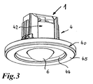
- FIGS. 1 and 3 can further be removed, extending at the level of the base of the lens unit 6, this surrounding a housing part in the form of a housing ring 40.
- This is about a plate-like housing part 41, with the housing ring 40 is connected to one of the other components of the detector Unit 1 receiving housing part 42 connected.
- the housing ring 40 has an inner cavity 43, in which a second light source 3 is arranged.
- a second light source 3 is arranged.
- This is for example in the form of light emitting diodes (LEDs), which are strung together stripe formed.
- the shape of the strip formed from the juxtaposed LEDs is advantageously adapted to the shape of the housing ring 40.
- the second light source 3 is in the in FIG. 1 shown embodiment of the plate-like housing part 41 is disposed in the interior of the housing ring 40.
- FIG. 2 projects in the embodiment variant of the detector unit 1 shown there, the lens unit 6 beyond the outer surface extension of the housing ring 40 addition.
- the housing part or housing ring 40 is approximately round in plan view, in principle, a different shape would be possible.
- the lens unit 6 and the housing ring 40 are spaced from each other, and the housing ring 40 has a circumferential Wall 44 toward the lens unit 6 on.
- the device 5 for detecting the brightness in the room is screened, shaded or sealed off from the light emitted by the second light source (s) arranged inside the housing ring 40. In this way, it is thus prevented that stray light from the second light source 3 falls on the device 5 for detecting the brightness in the room and falsifies the result of the brightness measurement.
- a wall 45 of the housing ring 40 can be made translucent or transparent in order to be able to transmit the light emitted by the at least one third light source 3 into the room or to be able to perceive it outside the detector unit 1.
- the detector unit 1 may be assigned to a control unit 11 or comprise the detector unit.
- the control unit 11 serves to control the light sources 3 and 10 or the detector unit 1 in different modes. As exemplary embodiments, a semi-automatic mode and a fully automatic mode of the detector unit 1 or control unit 11 are described in more detail below.
- the second light source 3 In the semi-automatic mode, when the brightness value falls below a certain brightness value, the second light source 3 is automatically switched on with a first light intensity. Upon detection of a movement or the presence of a person in the room or detection area of the detector unit 1, the second light source 3 is driven to the effect that it emits light with a second light intensity. After expiration of a predefinable or predetermined follow-up time, the second light source 3 lights up again with the first light intensity (eg as night light). If the first light source 10 of the room lighting is switched on by the manual actuation of a switch or pushbutton element 60 connected to the detector unit 1 during the follow-up time in which the second light source 3 emits light with the second light intensity, then the second light source 3 becomes complete switched off. Once the first light source 10 or the room lighting is turned off, either by pressing the associated with the detector unit 1 switch or button element 60 or automatically after the expiry of After-running time, the second light source 3 lights again with the first light intensity (eg as a
- the second light source 3 with the first light intensity is switched on automatically when it falls below a certain brightness value.
- the second light source 3 Upon detection of a movement or the presence of a person in the room or detection area of the detector unit 1, the second light source 3 is turned off and the room lighting is turned on. If no movement or presence of a person in the room or detection area of the detector unit 1 is detected more, the second light source 3 lights up again at the end of a predefinable or predefined follow-up time with the first light intensity.
- the second light source 3 is turned on with the second light intensity. If thereafter no movement or presence of a person in the room or detection area of the detector unit 1 is detected, the second light source 3 automatically lights up again after the predefinable or predefined delay time with the first light intensity.
- the at least one first light source 10 or the room lighting is switched off and the second light source 3 is switched on again as an orientation light when the detector or pushbutton element 60 connected to the detector unit 1 is actuated again.
- the latter can be switched back to the first light intensity or completely switched off after expiry of a follow-up time or automatically again with respect to its light intensity.
- a plurality of detector units 1 can be coupled together in order to expand the detection range.
- the detector unit 1 in the form of a master device which comprises the control unit 11, and, as a further variant embodiment, the detector unit 1 as a slave device without a control unit 11.
- the slave devices can be controlled via the master device.
- the provision of the master device and at least one slave device also entails the advantage that the detection range of the detector unit 1 working as a master device is widened, the light emitted or emitted by the second light source 3 illuminating the light source throughout the room.
- potentiometers or other adjusting devices can be provided, which are arranged in particular in the detector unit 1 behind a first cover element or a housing part. After setting, in particular, there are a plurality of light intensity values, the control unit 11 serving to make the respective selection of the light intensity value suitable for the desired mode of operation or the desired mode of the detector unit 1 from this set amount of light intensity values ,
- a detector unit for on-off switching on and off and dimming a first and a second light source, comprising at least one device for detecting a movement and / or the presence of a person in a room and
- a second light source is provided for providing a night and / or orientation light which is dimmable and optionally constant and / or presence-controlled, taking into account the light conditions prevailing in the room or in which the detector unit has at least one housing with at least one housing part, which is or can be arranged on the space-facing side of a room wall or ceiling, and i m and / or on the housing part, a second light source is arranged, wherein the arrangement in and / or on the housing part takes place so that the means for detecting the brightness in the room opposite to the second light source emitted or emitable light is shadowed or shaded
Landscapes
- Circuit Arrangement For Electric Light Sources In General (AREA)
Applications Claiming Priority (1)
| Application Number | Priority Date | Filing Date | Title |
|---|---|---|---|
| DE102015000024.1A DE102015000024A1 (de) | 2015-01-08 | 2015-01-08 | Melder-Einheit mit integrierter Nacht- und/oder Orientierungslichtfunktion |
Publications (1)
| Publication Number | Publication Date |
|---|---|
| EP3043626A1 true EP3043626A1 (fr) | 2016-07-13 |
Family
ID=55077396
Family Applications (1)
| Application Number | Title | Priority Date | Filing Date |
|---|---|---|---|
| EP16000003.0A Withdrawn EP3043626A1 (fr) | 2015-01-08 | 2016-01-07 | Unite d'avertisseur comprenant une fonction integree nuit et/ou d'eclairage d'orientation |
Country Status (2)
| Country | Link |
|---|---|
| EP (1) | EP3043626A1 (fr) |
| DE (1) | DE102015000024A1 (fr) |
Families Citing this family (2)
| Publication number | Priority date | Publication date | Assignee | Title |
|---|---|---|---|---|
| DE102017008933A1 (de) * | 2017-09-25 | 2019-03-28 | Friedrich Brück | Lichterfassungsoptik zur Konstantlichtregelung in großen Höhen |
| DE102022134087A1 (de) * | 2022-12-20 | 2024-06-20 | Albrecht Jung Gmbh & Co. Kg | Verfahren zum Betreiben eines Präsenzmelders |
Citations (6)
| Publication number | Priority date | Publication date | Assignee | Title |
|---|---|---|---|---|
| US6888323B1 (en) | 2002-09-25 | 2005-05-03 | The Watt Stopper, Inc. | Light management system device and method |
| US20080079568A1 (en) | 2006-09-29 | 2008-04-03 | Primous Christopher C | Occupancy sensor with dimmer feature and night light and method of lighting control using the same |
| GB2444527A (en) * | 2006-12-05 | 2008-06-11 | Cp Electronics Ltd | Dimmer switch with occupancy sensor |
| DE102009013289A1 (de) | 2009-03-14 | 2010-09-16 | Abb Ag | Master/Slave-System mit mindestens zwei Bewegungsmelder-Einheiten und Verfahren zum Betrieb eines solchen Master/Slave-Systems |
| DE102011090018A1 (de) * | 2011-01-11 | 2012-07-12 | Ridi - Leuchten Gmbh | Beleuchtungseinrichtung |
| DE202014001980U1 (de) * | 2013-03-06 | 2014-08-08 | Dietmar Friedrich Brück | Schalter-Einheit |
-
2015
- 2015-01-08 DE DE102015000024.1A patent/DE102015000024A1/de not_active Withdrawn
-
2016
- 2016-01-07 EP EP16000003.0A patent/EP3043626A1/fr not_active Withdrawn
Patent Citations (7)
| Publication number | Priority date | Publication date | Assignee | Title |
|---|---|---|---|---|
| US6888323B1 (en) | 2002-09-25 | 2005-05-03 | The Watt Stopper, Inc. | Light management system device and method |
| US20080079568A1 (en) | 2006-09-29 | 2008-04-03 | Primous Christopher C | Occupancy sensor with dimmer feature and night light and method of lighting control using the same |
| GB2444527A (en) * | 2006-12-05 | 2008-06-11 | Cp Electronics Ltd | Dimmer switch with occupancy sensor |
| US20100207532A1 (en) | 2006-12-05 | 2010-08-19 | C.P. Electronics Limited | Lighting controller |
| DE102009013289A1 (de) | 2009-03-14 | 2010-09-16 | Abb Ag | Master/Slave-System mit mindestens zwei Bewegungsmelder-Einheiten und Verfahren zum Betrieb eines solchen Master/Slave-Systems |
| DE102011090018A1 (de) * | 2011-01-11 | 2012-07-12 | Ridi - Leuchten Gmbh | Beleuchtungseinrichtung |
| DE202014001980U1 (de) * | 2013-03-06 | 2014-08-08 | Dietmar Friedrich Brück | Schalter-Einheit |
Also Published As
| Publication number | Publication date |
|---|---|
| DE102015000024A1 (de) | 2016-07-14 |
Similar Documents
| Publication | Publication Date | Title |
|---|---|---|
| DE102012204579B4 (de) | Intelligente Beleuchtungseinrichtung mit mehreren Leuchten, insbesondere Stehleuchten oder Tischaufbauleuchten, und Verfahren zum Betreiben einer solchen Beleuchtungseinrichtung | |
| DE102010032761A1 (de) | Verfahren zur Steuerung einer Beleuchtungsanlage, Steuerung für eine Beleuchtungsanlage und Beleuchtungsanlage | |
| DE202014001980U1 (de) | Schalter-Einheit | |
| EP3013123A1 (fr) | Système d'éclairage et procédé de commande correspondant | |
| EP2578928B1 (fr) | Dispositif d'éclairage avec lumière naturelle et artificielle | |
| EP3203153B1 (fr) | Appareil ménager comprenant une unité d'éclairage et procédé d'actionnement d'une unité d'éclairage | |
| EP3243363A1 (fr) | Système d'éclairage à détection de présence de personnes par utilisation de lumière à spectre différent | |
| DE102015000024A1 (de) | Melder-Einheit mit integrierter Nacht- und/oder Orientierungslichtfunktion | |
| DE202009009051U1 (de) | Leuchte | |
| DE102004045489B4 (de) | Sanitärarmatur | |
| DE102019131487A1 (de) | Meldereinheit, Meldersystem sowie Verfahren zum Betrieb des Meldersystems | |
| DE102007009038A1 (de) | Sanitärarmatur mit wählbarer Betriebsart | |
| DE202012104684U1 (de) | Elektrische Kerze | |
| DE102013225889A1 (de) | Panelleuchte | |
| DE102014115829A1 (de) | Vorrichtung und Verfahren zur Visualisierung von Messwerten | |
| EP3836758B1 (fr) | Procédé de commande d'un système d'éclairage d'un salle sanitaire et système d'éclairage d'un salle sanitaire | |
| EP2916624A2 (fr) | Procédé d'actionnement automatisé d'au moins une première source de lumière et d'au moins une seconde source de lumière | |
| EP0969702A2 (fr) | Dispositif de commande pour un système d'éclairage | |
| DE102014003253A1 (de) | Meldeeinheit zum Überwachen eines Raumes, Meldersystem sowie Verwendung des Meldersystems | |
| EP3188576B1 (fr) | Système d'éclairage, utilisation d'un système d'éclairage et dispositif d'éclairage destiné à être utilisé dans un système d'éclairage | |
| DE102011111970A1 (de) | LED-Modul-System mit einem LED-Modul | |
| DE102014216644B4 (de) | Branddetektionsvorrichtung zur Detektion eines Brandes sowie Verfahren zur Detektion eines Brandes mit der Branddetektionsvorrichtung | |
| DE102024204984A1 (de) | Kochfeldbeleuchtungssystem, Beleuchtungseinheit und Kochfeld | |
| DE202007004348U1 (de) | Digitale Dimmereinrichtung für Energiesparlampen | |
| WO2015062677A1 (fr) | Unité interrupteur |
Legal Events
| Date | Code | Title | Description |
|---|---|---|---|
| PUAI | Public reference made under article 153(3) epc to a published international application that has entered the european phase |
Free format text: ORIGINAL CODE: 0009012 |
|
| AK | Designated contracting states |
Kind code of ref document: A1 Designated state(s): AL AT BE BG CH CY CZ DE DK EE ES FI FR GB GR HR HU IE IS IT LI LT LU LV MC MK MT NL NO PL PT RO RS SE SI SK SM TR |
|
| AX | Request for extension of the european patent |
Extension state: BA ME |
|
| STAA | Information on the status of an ep patent application or granted ep patent |
Free format text: STATUS: REQUEST FOR EXAMINATION WAS MADE |
|
| 17P | Request for examination filed |
Effective date: 20170113 |
|
| RBV | Designated contracting states (corrected) |
Designated state(s): AL AT BE BG CH CY CZ DE DK EE ES FI FR GB GR HR HU IE IS IT LI LT LU LV MC MK MT NL NO PL PT RO RS SE SI SK SM TR |
|
| STAA | Information on the status of an ep patent application or granted ep patent |
Free format text: STATUS: EXAMINATION IS IN PROGRESS |
|
| 17Q | First examination report despatched |
Effective date: 20200319 |
|
| STAA | Information on the status of an ep patent application or granted ep patent |
Free format text: STATUS: THE APPLICATION IS DEEMED TO BE WITHDRAWN |
|
| 18D | Application deemed to be withdrawn |
Effective date: 20210330 |