EP3014325B1 - Kabelverwaltungsstruktur für ein faseroptisches verteilergestell - Google Patents
Kabelverwaltungsstruktur für ein faseroptisches verteilergestell Download PDFInfo
- Publication number
- EP3014325B1 EP3014325B1 EP14738764.1A EP14738764A EP3014325B1 EP 3014325 B1 EP3014325 B1 EP 3014325B1 EP 14738764 A EP14738764 A EP 14738764A EP 3014325 B1 EP3014325 B1 EP 3014325B1
- Authority
- EP
- European Patent Office
- Prior art keywords
- cable
- optical fiber
- fiber distribution
- cable support
- mounting
- Prior art date
- Legal status (The legal status is an assumption and is not a legal conclusion. Google has not performed a legal analysis and makes no representation as to the accuracy of the status listed.)
- Not-in-force
Links
Images


Classifications
-
- G—PHYSICS
- G02—OPTICS
- G02B—OPTICAL ELEMENTS, SYSTEMS OR APPARATUS
- G02B6/00—Light guides; Structural details of arrangements comprising light guides and other optical elements, e.g. couplings
- G02B6/44—Mechanical structures for providing tensile strength and external protection for fibres, e.g. optical transmission cables
- G02B6/4439—Auxiliary devices
- G02B6/444—Systems or boxes with surplus lengths
- G02B6/4452—Distribution frames
- G02B6/44524—Distribution frames with frame parts or auxiliary devices mounted on the frame and collectively not covering a whole width of the frame or rack
Definitions
- the present invention relates to a cable management structure for an optical fiber distribution rack.
- Optical fiber distribution systems include fiber terminations and other equipment which is typically rack mounted.
- US 2009/245746 A1 discloses a cable management structure, in which cable guides are provided in slots on both sides of a fiber distribution element.
- the invention relates to a cable management structure according to claim 1.
- the optical fiber distribution element is provided with linearly spaced mounting arrangements that are configured to engage with engagement features on the cable support guides.
- the cable support guides can be offset from each other in a grouped and staggered configuration to allow for cables extending along the height of the rack to be more efficiently managed.
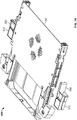
- an optical distribution frame or rack 10 is shown.
- the optical distribution frame 10 has a top portion 12, a base portion 14, a first side 16, and a second side 18.
- the optical distribution frame 10 is also shown as having a front side 20 and a back side 22.
- the optical distribution frame 10 is configured to support a plurality of optical fiber distribution elements 50, such as a sliding chassis type element configured for use as a patch panel to connect patch cables entering one side of the element 50 to an incoming cable, such as a distribution cable or a feeder cable entering an opposite side of the element 50.
- a sliding chassis type element configured for use as a patch panel to connect patch cables entering one side of the element 50 to an incoming cable, such as a distribution cable or a feeder cable entering an opposite side of the element 50.
- an incoming cable such as a distribution cable or a feeder cable entering an opposite side of the element 50.
- WO 2014/118227 A1 WO 2014/118227 A1
- each optical fiber distribution element 50 is mounted to the optical distribution frame 10 near the back side 22 of the frame 10, and is provided with a first side 52 and an opposite second side 54 at which cables may enter or exit the element 50.
- the optical distribution frame 10 is also shown as being provided with one or more cable management structures 100.
- the cable management structures 100 provide for a staggered cable routing structure that receives cables from either the first or second side 52, 54 of each mounted optical fiber distribution element 50, and directs the cables along one of staggered pathways 180, 182, and 184. By staggering the pathways 180, 182, and 184, the number of cables that can be routed within the same footprint is increased as the available depth along the side(s) of the rack 10 is better optimized. It is noted that although three staggered pathways are shown, the cable management structure 100 can be provided with fewer or more staggered pathways, or with a single continuously sloped pathway.
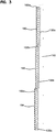
- the cable management structure 100 includes a plurality of cable support guides 102 that are attached to a side channel frame 130 that extends vertically between the base portion 14 and the top portion 12 of the optical fiber distribution rack 10.
- the side channel frame 130 is provided with mounting arrangements 132 (132a, 132b, 132c) that engage with a corresponding engagement feature 110 on each of the cable support guides 102.
- the mounting arrangements 132 and engagement features 110 allow for a removable snap-fit type connection between the side channel frame 130 and cable support guides 102.
- mounting arrangement 132 is provided with a pair of slots 130c and aperture 130d that engage with corresponding legs 110a and latch tab 110b on the cable support guide 102.
- the mounting arrangements 132 and engagement features 110 may be configured to engage each other with other types of attachment means, such as mechanical fasteners and/or permanent connection features.
- the side channel frame 130 and cable support guides 102 could be formed as an integral structure.
- each of the cable support guides 102 is provided with a central opening 103, and a cable support pathway 104 that extends from a front face 106 to a rear face 108 of the cable support guide 102.
- the cable support pathway 104 receives and frictionally secures a cable (not shown) extending from the first side 52 (or the second side 54) of the optical fiber distribution element 50.
- pathway 104 is configured as a circuitous or tortious pathway to further retain the cable within the support guide 102.
- the cable support pathway 104 is also configured to route the cable to one of the cable pathways 180, 182, 184 depending upon the mounting location of the cable support guide 102 with respect to the side channel frame 130.
- the mounting arrangements 132 on the side channel frame 130 are provided in a plurality of staggered groups such that a plane defined by the front face 106 of the cable support guides 102 in one or more of the staggered groups is horizontally recessed in a direction towards the rear face 108 of the cable support guide 102.
- mounting arrangements 132a are provided for a plurality of cable support guides 102a such that the front face 106 of the cable support guides 102a extends along a first plane 190.
- mounting arrangements 132b are provided for a plurality of cable support guides 102b such that the front face 106 of the cable support guides 102b extends along a second plane 192 while mounting arrangements 132c are provided for a plurality of cable support guides 102c such that the front face 106 of the cable support guides 102c extends along a third plane 194.
- the first plane 190 is horizontally recessed from the second plane 192 while the second plane 192 is in turn horizontally recessed from the third plane 194.
- cables extending through the first group of cable support guides 102a are routed along the first cable pathway 180
- cables extending through the second group of cable support guides 102b are routed along the second cable pathway 182
- cables extending through the third group of cable support guides 102c are routed along the third cable pathway 182.
- this configuration allows for the cables to be grouped together and oriented in a manner that takes advantage of the available depth of the distribution rack 10.
- the side channel frame 130 is defined as having a main body 134 extending between a first end 130a and a second end 130b.
- the main body 134 can act to separate the cables in the pathways 180, 182, 184 from the optical fiber distribution elements 50.
- the side channel frame 130 main body 134 can also be provided with a plurality of mounting holes 136 for securing the side channel frame 130 to the optical fiber distribution rack, for example, with mechanical fasteners.
- the side channel frame can be rotated or oriented such that either end 130a, 130b is in an upward position relative to the optical fiber distribution rack 10.
- the orientation of Figure 4 is similar to that shown for the side channel frame 130 located nearest to the first side 16 of the optical fiber distribution rack 10 while the orientation of Figure 5 is similar to that shown for the side channel frame 130 located nearest to the second side 18 of the optical fiber distribution rack 10. Accordingly, the orientation shown in Figure 4 allows for cables to be routed from the cable support guides 102 downwardly in the cable routing pathways 180, 182, 184 towards the base portion 14 of the optical fiber distribution rack 10. Such a configuration is beneficial when, for example, the cables are distributed beneath the floor supporting the optical fiber distribution rack 10.
- the orientation shown in Figure 5 allows for cables to be routed from the cable support guides 120 upwardly in the cable routing pathways 180, 182, 184 towards the top portion 12 of the optical fiber distribution rack 10.
- Such a configuration is beneficial when, for example, the cables are distributed at a level above the optical fiber distribution rack 10.
- FIG. 8 and 9 an alternative example, not being part of the present invention, of a cable management structure 200 is shown.
- the above description of the first example shown in Figures 1-7 is applicable to the second example, and is incorporated into the description of the second example by reference in its entirety. Where components are the same or substantially similar, like reference numbers will be used. Differences between the second and first examples will be discussed here, the primary differences being that the second example includes cable support guides 202 that are directly attached to the optical fiber distribution element 50 rather than to a side channel frame 130.
- the cable management structure 200 includes cable support guides 202 that have a cable pathway 204 that extends between a front face 206 and a rear face 208.
- pathway 204 is configured as a circuitous or tortious pathway to further retain the cable within the support guide 202.
- Each cable support guide 202 is also provided with an engagement feature 210 such that the cable support guide 202 can be removably attached to one of the sides 52, 54 of the optical fiber distribution element 50.
- each optical fiber distribution element 50 may be provided with a plurality of mounting arrangements 60.
- the distribution element 50 has a front end 56 and a rear end 58 extending between the first side portion 52 and a second side portion 54, wherein the plurality of mounting arrangements 60 are linearly spaced between the front end 56 and rear end 58.
- the optical fiber distribution element 50 includes a first mounting arrangement 60a, a second mounting arrangement 60b, and a third mounting arrangement 60c.
- mounting arrangement 60a, 60b, 60c should be selected as the mounting location for a cable support guide 202 in order to define the cable routing pathways 180, 182, and/or 184 as desired.
- cable support guide 202a is attached to mounting arrangement 60a
- cable support guide 202b is attached to mounting arrangement 60b
- cable support guide 202c is attached to mounting arrangement 60c.
- the mounting arrangement 60 and engagement features 210 allow for a removable snap-fit type connection between the optical fiber distribution element 50 and the cable support guides 202.
- mounting arrangement 60 is provided with a pair of narrowing slots 62 and a tab 64 that engage with corresponding legs 210a and the front face 206 of the cable support guide 102.
- mounting arrangements 60 and engagement features 210 may be configured to engage each other with other types of attachment means, such as mechanical fasteners and/or permanent connection features.
- Figures 8 and 9 show an example in which three vertically stacked optical fiber distribution elements 50 are provided with cable support guides 202 mounted in different locations, it should be understood that multiples of each attachment configuration can be provided in order to develop a support guide profile similar to that shown in Figure 1 to provide distinct cable routing pathways, for example pathways 180, 182, 184.
- a cable management structure 300 is shown. As some of the features of this embodiment are similar to the prior examples described above, portions of the above description of Figures 1-9 are applicable to this embodiment, and are incorporated into the description of this embodiment by reference in its entirety. Where components are the same or substantially similar, like reference numbers will be used. Differences between this embodiment and the first and second examples will be discussed here, the primary differences being that, according to the invention, the cable management structure includes a cable support guide 302 which includes an extension, and is directly attached to the optical fiber distribution element 50, like cable support guide 202.
- the cable management structure 300 includes cable support guides 302 that have a cable pathway 304 that extends between a front face and a rear face.
- a pathway 304 is configured as a circuitous or tortious pathway to further retain the cable within the support guide 302.
- Each cable support guide 302 is also provided with an engagement features 310 such that the cable support guide 302 can be removably attached to one of the sides 52, 54 of the optical fiber distribution element 50.
- each optical fiber distribution element 50 is provided with a plurality of mounting arrangements 60.
- An installer can install cable support guides 302 in a first position as shown in Figures 11-14 .
- Cable support guides 302 can be mounted in a second position as shown in Figures 16-19 .
- the cable support guide 302 of Figures 16-19 is shown in Figure 15 .
- the extension 312 of cable support guide 302 as shown in Figure 10 can be removed to form the cable support guide 302 of Figure 15 .
- the extension 312 can be removed by breaking off portions 314 and 316. Compare Figures 12 and 17 to see the staggering effect of the two different cable guides 302, one with the extension 312 and one without.
Landscapes
- Physics & Mathematics (AREA)
- General Physics & Mathematics (AREA)
- Optics & Photonics (AREA)
- Light Guides In General And Applications Therefor (AREA)
Claims (5)
- Kabelführungsstruktur (300) für ein Lichtwellenleiterverteilungsgestell (10), umfassend:(a) mindestens ein Lichtwellenleiterverteilungselement (50), das derart konfiguriert ist, dass es von dem Lichtwellenleiterverteilungsgestell (10) gestützt wird und gegenüberliegend einen ersten und einen zweiten vertikalen Seitenabschnitt (52, 54) aufweist, die sich zwischen einem Vorderende (56) und einem Hinterende (58) erstrecken, wobei jeder von dem ersten und dem zweiten vertikalen Seitenabschnitt (52, 54) mehrere getrennte diskrete Befestigungsanordnungen (60) umfasst, die zwischen dem Vorderende (56) und dem Hinterende (58) linear beabstandet sind; und(b) eine erste Kabelhalterführung (302), die einen Kabelweg (304) definiert, der sich zwischen einer Vorderfläche und einer Hinterfläche erstreckt, wobei die erste Kabelhalterführung (302) zum selektiven Befestigen an einer der mehreren Befestigungsanordnungen (60) an dem ersten vertikalen Seitenabschnitt (52) und zum Aufnehmen eines Kabels konfiguriert ist, das sich von dem mindestens einen Lichtwellenleiterverteilungselement (50) erstreckt, und(c) eine zweite Kabelhalterführung (302), die einen Kabelweg (304) definiert, der sich zwischen einer Vorderfläche und einer Hinterfläche erstreckt, wobei die zweite Kabelhalterführung (302) zum selektiven Befestigen an einer der mehreren Befestigungsanordnungen (60) an dem zweiten vertikalen Seitenabschnitt (54) und zum Aufnehmen eines Kabels konfiguriert ist, das sich von dem mindestens einen Lichtwellenleiterverteilungselement (50) erstreckt;wobei die erste und die zweite Kabelhalterführung (302) jeweils mit einem Eingriffsmerkmal (310) zum lösbaren Eingriff in eine der mehreren Befestigungsanordnungen (60) versehen sind; und
wobei die erste und die zweite Kabelhalterführung (302) einen lösbaren Abschnitt in der Form einer Verlängerung (312) umfasst. - Kabelführungsstruktur (300) nach Anspruch 1, wobei jeder von dem ersten und dem zweiten vertikalen Seitenabschnitt (52, 54) des Lichtwellenleiterverteilungselements (50) eine erste Befestigungsanordnung (60a), eine zweite Befestigungsanordnung (60b) und eine dritte Befestigungsanordnung (60c) aufweist.
- Kabelführungsstruktur (300) nach Anspruch 1, wobei das Lichtwellenleiterverteilungselement (50) ein Gleitchassiselement ist, das zur Verwendung als Rangierfeld konfiguriert ist, um Rangierkabel, die in eine Seite des Lichtwellenleiterverteilungselements (50) eintreten, mit einem ankommenden Kabel zu verbinden, das in eine gegenüberliegende Seite des Lichtwellenleiterverteilungselements (50) eintritt.
- Kabelführungsstruktur (300) nach Anspruch 1, wobei jede von der ersten und der zweiten Kabelhalterführung (302) eine Schnappverbindung mit der Befestigungsanordnung (60) bildet, an der die Kabelhalterführung (302) befestigt ist.
- Kabelführungsstruktur (300) nach Anspruch 4, wobei jede der mehreren Befestigungsanordnungen (60) ein Paar von sich verengenden Schlitzen (62) und einen Mitnehmer (64) zum Eingriff in entsprechende Schenkel (310a) und der Vorderfläche von jeder der ersten und der zweiten Kabelhalterführung (302) aufweist.
Applications Claiming Priority (3)
| Application Number | Priority Date | Filing Date | Title |
|---|---|---|---|
| US201361840835P | 2013-06-28 | 2013-06-28 | |
| US201461986539P | 2014-04-30 | 2014-04-30 | |
| PCT/EP2014/063717 WO2014207210A1 (en) | 2013-06-28 | 2014-06-27 | Optical fiber distribution system with staggered cable guides |
Publications (2)
| Publication Number | Publication Date |
|---|---|
| EP3014325A1 EP3014325A1 (de) | 2016-05-04 |
| EP3014325B1 true EP3014325B1 (de) | 2021-03-24 |
Family
ID=51177036
Family Applications (1)
| Application Number | Title | Priority Date | Filing Date |
|---|---|---|---|
| EP14738764.1A Not-in-force EP3014325B1 (de) | 2013-06-28 | 2014-06-27 | Kabelverwaltungsstruktur für ein faseroptisches verteilergestell |
Country Status (6)
| Country | Link |
|---|---|
| US (2) | US9958631B2 (de) |
| EP (1) | EP3014325B1 (de) |
| AU (2) | AU2014300959B2 (de) |
| NZ (1) | NZ715517A (de) |
| SA (1) | SA515370327B1 (de) |
| WO (1) | WO2014207210A1 (de) |
Families Citing this family (21)
| Publication number | Priority date | Publication date | Assignee | Title |
|---|---|---|---|---|
| ES2953122T3 (es) | 2013-01-29 | 2023-11-08 | CommScope Connectivity Belgium BVBA | Sistema de distribución de fibra óptica |
| AP2015008820A0 (en) | 2013-04-24 | 2015-10-31 | Adc Czech Republic Sro | Optical fiber distribution system |
| HUE053625T2 (hu) | 2013-04-24 | 2021-07-28 | CommScope Connectivity Belgium BVBA | Optikai szálelosztási rendszer |
| AU2014300959B2 (en) | 2013-06-28 | 2018-09-27 | CommScope Connectivity Belgium BVBA | Optical fiber distribution system with staggered cable guides |
| EP3844972B1 (de) | 2018-08-31 | 2022-08-03 | CommScope Connectivity Belgium BVBA | Rahmenanordnungen für glasfaserverteilungselemente |
| EP3844973B1 (de) | 2018-08-31 | 2024-11-06 | CommScope Connectivity Belgium BVBA | Rahmenanordnungen für optische faserverteilungselemente |
| WO2020043911A1 (en) | 2018-08-31 | 2020-03-05 | CommScope Connectivity Belgium BVBA | Frame assemblies for optical fiber distribution elements |
| MX2021002249A (es) | 2018-08-31 | 2021-07-15 | CommScope Connectivity Belgium BVBA | Unidades de marco para elementos de distribucion de fibra optica. |
| EP3844547A1 (de) | 2018-08-31 | 2021-07-07 | CommScope Connectivity Belgium BVBA | Rahmenanordnungen für glasfaserverteilungselemente |
| WO2020084012A1 (en) | 2018-10-23 | 2020-04-30 | CommScope Connectivity Belgium BVBA | Frame assemblies for optical fiber distribution elements |
| EP4246199A3 (de) | 2019-01-15 | 2023-12-20 | CommScope Connectivity Belgium BVBA | Spleissbare patch-anordnung mit beweglichen adaptern |
| EP3914947B1 (de) | 2019-01-25 | 2025-10-22 | CommScope Connectivity Belgium BVBA | Rahmenanordnungen für optische faserverteilungselemente |
| EP3931611A4 (de) | 2019-03-01 | 2022-12-07 | CommScope Technologies LLC | Vorrichtungen, baugruppen und verfahren zur verankerung von komponenten von telekommunikationskabeln |
| WO2021071844A1 (en) | 2019-10-07 | 2021-04-15 | Commscope Technologies Llc | Fiber distribution hub including sealed splice module |
| US12174443B2 (en) | 2020-01-22 | 2024-12-24 | CommScope Connectivity Belgium BVBA | Cable termination units for optical fiber distribution elements |
| EP4094108B1 (de) | 2020-01-24 | 2025-06-18 | CommScope Connectivity Belgium BVBA | Telekommunikationsverteilungselemente |
| EP4100777A1 (de) | 2020-02-07 | 2022-12-14 | CommScope Connectivity Belgium BVBA | Telekommunikationsmodulanordnungen |
| EP4179370A1 (de) | 2020-07-09 | 2023-05-17 | Commscope Connectivy Belgium BV | Telekommunikationsanordnungen |
| US20230314751A1 (en) * | 2020-08-14 | 2023-10-05 | Commscope Technologies Llc | Optical fiber sheath holders for fiber optic closure organizers |
| EP3992683B1 (de) | 2020-11-02 | 2025-07-09 | CommScope Connectivity Belgium BV | Spleissbare patch-anordnung mit beweglichen adaptern |
| WO2023212211A1 (en) * | 2022-04-29 | 2023-11-02 | Commscope Technologies Llc | Configurable optical fiber sheath holders and sheath retainer storage for optical fiber organizers |
Citations (2)
| Publication number | Priority date | Publication date | Assignee | Title |
|---|---|---|---|---|
| US20090245746A1 (en) * | 2008-03-28 | 2009-10-01 | Dennis Krampotich | Universal cable management panel |
| WO2014090843A1 (en) * | 2012-12-11 | 2014-06-19 | Tyco Electronics Raychem Bvba | Universal cable management system for telecommunications rack |
Family Cites Families (24)
| Publication number | Priority date | Publication date | Assignee | Title |
|---|---|---|---|---|
| US5339379A (en) | 1993-06-18 | 1994-08-16 | Telect, Inc. | Telecommunication fiber optic cable distribution apparatus |
| JP2000286574A (ja) | 1999-03-31 | 2000-10-13 | Nec Eng Ltd | ケーブルクランプ・ユニット |
| US6256444B1 (en) * | 1999-09-21 | 2001-07-03 | Antec Corporation | Adjustable guide for organizing optical fibers in an equipment rack |
| US6504988B1 (en) | 2000-01-24 | 2003-01-07 | Adc Telecommunications, Inc. | Cable management panel with sliding drawer |
| US6539161B2 (en) * | 2001-03-16 | 2003-03-25 | Adc Telecommunications, Inc. | Cable routing clip |
| US7079744B2 (en) | 2001-07-06 | 2006-07-18 | Adc Telecommunications, Inc. | Cable management panel with sliding drawer and methods |
| US7086539B2 (en) | 2002-10-21 | 2006-08-08 | Adc Telecommunications, Inc. | High density panel with rotating tray |
| US6870734B2 (en) | 2003-05-30 | 2005-03-22 | Adc Telecommunications, Inc. | Fiber containment system |
| US7171099B2 (en) | 2003-07-31 | 2007-01-30 | Adc Telecommunications, Inc. | Slide arrangement for cable drawer |
| US7171100B2 (en) * | 2004-11-03 | 2007-01-30 | Adc Telecommunications, Inc. | Optical fiber slack storage tray for distribution cabinet |
| CA2725393A1 (en) | 2008-04-11 | 2009-10-15 | Adc Telecommunications, Inc. | Fiber management panel |
| EP2534847B1 (de) | 2010-02-12 | 2018-06-27 | CommScope Technologies LLC | Kommunikationssystem mit einer platte mit lamellen |
| DE102011012438B4 (de) | 2010-11-04 | 2016-04-14 | Berthold Sichert Gmbh | Baukasten für Befestigungsvorrichtung |
| US8842445B2 (en) * | 2010-11-15 | 2014-09-23 | Adc Telecommunications, Inc. | Cable management in rack systems |
| US9081164B2 (en) | 2011-08-24 | 2015-07-14 | Adc Telecommunications, Inc. | Fiber management panel |
| ES2953122T3 (es) | 2013-01-29 | 2023-11-08 | CommScope Connectivity Belgium BVBA | Sistema de distribución de fibra óptica |
| US9128262B2 (en) | 2013-02-05 | 2015-09-08 | Adc Telecommunications, Inc. | Slidable telecommunications tray with cable slack management |
| US9435975B2 (en) | 2013-03-15 | 2016-09-06 | Commscope Technologies Llc | Modular high density telecommunications frame and chassis system |
| HUE053625T2 (hu) | 2013-04-24 | 2021-07-28 | CommScope Connectivity Belgium BVBA | Optikai szálelosztási rendszer |
| AP2015008820A0 (en) | 2013-04-24 | 2015-10-31 | Adc Czech Republic Sro | Optical fiber distribution system |
| AU2014300959B2 (en) | 2013-06-28 | 2018-09-27 | CommScope Connectivity Belgium BVBA | Optical fiber distribution system with staggered cable guides |
| EP3058409B1 (de) | 2013-10-18 | 2019-12-04 | CommScope Connectivity Belgium BVBA | Montagesystem für telekommunikationsverteilungselemente |
| EP3172902B1 (de) | 2014-07-25 | 2018-06-27 | CommScope Connectivity Belgium BVBA | Elemente zur verteilung von telekommunikationen |
| DK3278159T3 (da) | 2015-04-03 | 2023-11-20 | CommScope Connectivity Belgium BVBA | Telekommunikationsfordelingselementer |
-
2014
- 2014-06-27 AU AU2014300959A patent/AU2014300959B2/en not_active Ceased
- 2014-06-27 EP EP14738764.1A patent/EP3014325B1/de not_active Not-in-force
- 2014-06-27 US US14/901,497 patent/US9958631B2/en active Active
- 2014-06-27 WO PCT/EP2014/063717 patent/WO2014207210A1/en not_active Ceased
- 2014-06-27 NZ NZ715517A patent/NZ715517A/en not_active IP Right Cessation
-
2015
- 2015-12-28 SA SA515370327A patent/SA515370327B1/ar unknown
-
2018
- 2018-03-22 US US15/928,598 patent/US10345546B2/en active Active
- 2018-12-24 AU AU2018282687A patent/AU2018282687A1/en not_active Abandoned
Patent Citations (2)
| Publication number | Priority date | Publication date | Assignee | Title |
|---|---|---|---|---|
| US20090245746A1 (en) * | 2008-03-28 | 2009-10-01 | Dennis Krampotich | Universal cable management panel |
| WO2014090843A1 (en) * | 2012-12-11 | 2014-06-19 | Tyco Electronics Raychem Bvba | Universal cable management system for telecommunications rack |
Also Published As
| Publication number | Publication date |
|---|---|
| WO2014207210A1 (en) | 2014-12-31 |
| NZ715517A (en) | 2019-03-29 |
| AU2014300959A1 (en) | 2016-01-21 |
| SA515370327B1 (ar) | 2018-03-29 |
| US20160370553A1 (en) | 2016-12-22 |
| US9958631B2 (en) | 2018-05-01 |
| EP3014325A1 (de) | 2016-05-04 |
| AU2014300959B2 (en) | 2018-09-27 |
| US20180314026A1 (en) | 2018-11-01 |
| AU2018282687A1 (en) | 2019-01-24 |
| US10345546B2 (en) | 2019-07-09 |
Similar Documents
| Publication | Publication Date | Title |
|---|---|---|
| EP3014325B1 (de) | Kabelverwaltungsstruktur für ein faseroptisches verteilergestell | |
| US9817202B2 (en) | Universal cable management system for telecommunications rack | |
| US8464984B2 (en) | Cable management guide | |
| US7963486B2 (en) | Cable management assembly with variably spaced projections | |
| US10261279B1 (en) | System and method for distributing high fiber count optical cable to network racks | |
| US7995357B2 (en) | Cable management arrangement for a telecommunications cabinet | |
| US20110192631A1 (en) | Vertical cable protection and management trough | |
| US8119915B2 (en) | Cable management patch panel system with vertical ducting | |
| KR101399938B1 (ko) | 케이블 트레이 | |
| CA2602333A1 (en) | Field convertible telecommunications distribution pedestal | |
| US8628157B2 (en) | Cabinet cable management | |
| WO2019005758A1 (en) | SYSTEM AND METHOD FOR JOINING AND DISTRIBUTING SINGLE OPTICAL FIBER CABLE TO MULTIPLE BAY SHELVES | |
| US11502488B2 (en) | Cable management assembly for variable length cables | |
| ES2700525T3 (es) | Dispositivo de terminación de cable | |
| US8162700B2 (en) | Connection block mounting frame | |
| KR102608638B1 (ko) | 건축물 케이블 트레이 스페이서 | |
| JP2020068610A (ja) | 分電盤ケースの基台 | |
| US7261590B2 (en) | Rack-mounted punchdown panel and punchdown base | |
| US20210116662A1 (en) | Patch Panel and Distribution Frame |
Legal Events
| Date | Code | Title | Description |
|---|---|---|---|
| PUAI | Public reference made under article 153(3) epc to a published international application that has entered the european phase |
Free format text: ORIGINAL CODE: 0009012 |
|
| 17P | Request for examination filed |
Effective date: 20160128 |
|
| AK | Designated contracting states |
Kind code of ref document: A1 Designated state(s): AL AT BE BG CH CY CZ DE DK EE ES FI FR GB GR HR HU IE IS IT LI LT LU LV MC MK MT NL NO PL PT RO RS SE SI SK SM TR |
|
| AX | Request for extension of the european patent |
Extension state: BA ME |
|
| DAX | Request for extension of the european patent (deleted) | ||
| STAA | Information on the status of an ep patent application or granted ep patent |
Free format text: STATUS: EXAMINATION IS IN PROGRESS |
|
| 17Q | First examination report despatched |
Effective date: 20170912 |
|
| GRAP | Despatch of communication of intention to grant a patent |
Free format text: ORIGINAL CODE: EPIDOSNIGR1 |
|
| STAA | Information on the status of an ep patent application or granted ep patent |
Free format text: STATUS: GRANT OF PATENT IS INTENDED |
|
| INTG | Intention to grant announced |
Effective date: 20201021 |
|
| GRAS | Grant fee paid |
Free format text: ORIGINAL CODE: EPIDOSNIGR3 |
|
| GRAA | (expected) grant |
Free format text: ORIGINAL CODE: 0009210 |
|
| STAA | Information on the status of an ep patent application or granted ep patent |
Free format text: STATUS: THE PATENT HAS BEEN GRANTED |
|
| AK | Designated contracting states |
Kind code of ref document: B1 Designated state(s): AL AT BE BG CH CY CZ DE DK EE ES FI FR GB GR HR HU IE IS IT LI LT LU LV MC MK MT NL NO PL PT RO RS SE SI SK SM TR |
|
| REG | Reference to a national code |
Ref country code: GB Ref legal event code: FG4D |
|
| REG | Reference to a national code |
Ref country code: CH Ref legal event code: EP |
|
| REG | Reference to a national code |
Ref country code: IE Ref legal event code: FG4D |
|
| REG | Reference to a national code |
Ref country code: AT Ref legal event code: REF Ref document number: 1375078 Country of ref document: AT Kind code of ref document: T Effective date: 20210415 Ref country code: DE Ref legal event code: R096 Ref document number: 602014075937 Country of ref document: DE |
|
| REG | Reference to a national code |
Ref country code: LT Ref legal event code: MG9D |
|
| PG25 | Lapsed in a contracting state [announced via postgrant information from national office to epo] |
Ref country code: GR Free format text: LAPSE BECAUSE OF FAILURE TO SUBMIT A TRANSLATION OF THE DESCRIPTION OR TO PAY THE FEE WITHIN THE PRESCRIBED TIME-LIMIT Effective date: 20210625 Ref country code: FI Free format text: LAPSE BECAUSE OF FAILURE TO SUBMIT A TRANSLATION OF THE DESCRIPTION OR TO PAY THE FEE WITHIN THE PRESCRIBED TIME-LIMIT Effective date: 20210324 Ref country code: HR Free format text: LAPSE BECAUSE OF FAILURE TO SUBMIT A TRANSLATION OF THE DESCRIPTION OR TO PAY THE FEE WITHIN THE PRESCRIBED TIME-LIMIT Effective date: 20210324 Ref country code: BG Free format text: LAPSE BECAUSE OF FAILURE TO SUBMIT A TRANSLATION OF THE DESCRIPTION OR TO PAY THE FEE WITHIN THE PRESCRIBED TIME-LIMIT Effective date: 20210624 Ref country code: NO Free format text: LAPSE BECAUSE OF FAILURE TO SUBMIT A TRANSLATION OF THE DESCRIPTION OR TO PAY THE FEE WITHIN THE PRESCRIBED TIME-LIMIT Effective date: 20210624 |
|
| PG25 | Lapsed in a contracting state [announced via postgrant information from national office to epo] |
Ref country code: RS Free format text: LAPSE BECAUSE OF FAILURE TO SUBMIT A TRANSLATION OF THE DESCRIPTION OR TO PAY THE FEE WITHIN THE PRESCRIBED TIME-LIMIT Effective date: 20210324 Ref country code: LV Free format text: LAPSE BECAUSE OF FAILURE TO SUBMIT A TRANSLATION OF THE DESCRIPTION OR TO PAY THE FEE WITHIN THE PRESCRIBED TIME-LIMIT Effective date: 20210324 Ref country code: SE Free format text: LAPSE BECAUSE OF FAILURE TO SUBMIT A TRANSLATION OF THE DESCRIPTION OR TO PAY THE FEE WITHIN THE PRESCRIBED TIME-LIMIT Effective date: 20210324 |
|
| REG | Reference to a national code |
Ref country code: NL Ref legal event code: MP Effective date: 20210324 |
|
| REG | Reference to a national code |
Ref country code: AT Ref legal event code: MK05 Ref document number: 1375078 Country of ref document: AT Kind code of ref document: T Effective date: 20210324 |
|
| PG25 | Lapsed in a contracting state [announced via postgrant information from national office to epo] |
Ref country code: NL Free format text: LAPSE BECAUSE OF FAILURE TO SUBMIT A TRANSLATION OF THE DESCRIPTION OR TO PAY THE FEE WITHIN THE PRESCRIBED TIME-LIMIT Effective date: 20210324 |
|
| PG25 | Lapsed in a contracting state [announced via postgrant information from national office to epo] |
Ref country code: SM Free format text: LAPSE BECAUSE OF FAILURE TO SUBMIT A TRANSLATION OF THE DESCRIPTION OR TO PAY THE FEE WITHIN THE PRESCRIBED TIME-LIMIT Effective date: 20210324 Ref country code: AT Free format text: LAPSE BECAUSE OF FAILURE TO SUBMIT A TRANSLATION OF THE DESCRIPTION OR TO PAY THE FEE WITHIN THE PRESCRIBED TIME-LIMIT Effective date: 20210324 Ref country code: LT Free format text: LAPSE BECAUSE OF FAILURE TO SUBMIT A TRANSLATION OF THE DESCRIPTION OR TO PAY THE FEE WITHIN THE PRESCRIBED TIME-LIMIT Effective date: 20210324 Ref country code: CZ Free format text: LAPSE BECAUSE OF FAILURE TO SUBMIT A TRANSLATION OF THE DESCRIPTION OR TO PAY THE FEE WITHIN THE PRESCRIBED TIME-LIMIT Effective date: 20210324 Ref country code: EE Free format text: LAPSE BECAUSE OF FAILURE TO SUBMIT A TRANSLATION OF THE DESCRIPTION OR TO PAY THE FEE WITHIN THE PRESCRIBED TIME-LIMIT Effective date: 20210324 |
|
| PG25 | Lapsed in a contracting state [announced via postgrant information from national office to epo] |
Ref country code: PT Free format text: LAPSE BECAUSE OF FAILURE TO SUBMIT A TRANSLATION OF THE DESCRIPTION OR TO PAY THE FEE WITHIN THE PRESCRIBED TIME-LIMIT Effective date: 20210726 Ref country code: PL Free format text: LAPSE BECAUSE OF FAILURE TO SUBMIT A TRANSLATION OF THE DESCRIPTION OR TO PAY THE FEE WITHIN THE PRESCRIBED TIME-LIMIT Effective date: 20210324 Ref country code: ES Free format text: LAPSE BECAUSE OF FAILURE TO SUBMIT A TRANSLATION OF THE DESCRIPTION OR TO PAY THE FEE WITHIN THE PRESCRIBED TIME-LIMIT Effective date: 20210324 Ref country code: RO Free format text: LAPSE BECAUSE OF FAILURE TO SUBMIT A TRANSLATION OF THE DESCRIPTION OR TO PAY THE FEE WITHIN THE PRESCRIBED TIME-LIMIT Effective date: 20210324 Ref country code: SK Free format text: LAPSE BECAUSE OF FAILURE TO SUBMIT A TRANSLATION OF THE DESCRIPTION OR TO PAY THE FEE WITHIN THE PRESCRIBED TIME-LIMIT Effective date: 20210324 Ref country code: IS Free format text: LAPSE BECAUSE OF FAILURE TO SUBMIT A TRANSLATION OF THE DESCRIPTION OR TO PAY THE FEE WITHIN THE PRESCRIBED TIME-LIMIT Effective date: 20210724 |
|
| REG | Reference to a national code |
Ref country code: DE Ref legal event code: R097 Ref document number: 602014075937 Country of ref document: DE |
|
| PG25 | Lapsed in a contracting state [announced via postgrant information from national office to epo] |
Ref country code: DK Free format text: LAPSE BECAUSE OF FAILURE TO SUBMIT A TRANSLATION OF THE DESCRIPTION OR TO PAY THE FEE WITHIN THE PRESCRIBED TIME-LIMIT Effective date: 20210324 Ref country code: MC Free format text: LAPSE BECAUSE OF FAILURE TO SUBMIT A TRANSLATION OF THE DESCRIPTION OR TO PAY THE FEE WITHIN THE PRESCRIBED TIME-LIMIT Effective date: 20210324 Ref country code: AL Free format text: LAPSE BECAUSE OF FAILURE TO SUBMIT A TRANSLATION OF THE DESCRIPTION OR TO PAY THE FEE WITHIN THE PRESCRIBED TIME-LIMIT Effective date: 20210324 |
|
| REG | Reference to a national code |
Ref country code: CH Ref legal event code: PL |
|
| PLBE | No opposition filed within time limit |
Free format text: ORIGINAL CODE: 0009261 |
|
| STAA | Information on the status of an ep patent application or granted ep patent |
Free format text: STATUS: NO OPPOSITION FILED WITHIN TIME LIMIT |
|
| GBPC | Gb: european patent ceased through non-payment of renewal fee |
Effective date: 20210627 |
|
| PG25 | Lapsed in a contracting state [announced via postgrant information from national office to epo] |
Ref country code: SI Free format text: LAPSE BECAUSE OF FAILURE TO SUBMIT A TRANSLATION OF THE DESCRIPTION OR TO PAY THE FEE WITHIN THE PRESCRIBED TIME-LIMIT Effective date: 20210324 |
|
| 26N | No opposition filed |
Effective date: 20220104 |
|
| REG | Reference to a national code |
Ref country code: BE Ref legal event code: MM Effective date: 20210630 |
|
| PG25 | Lapsed in a contracting state [announced via postgrant information from national office to epo] |
Ref country code: LU Free format text: LAPSE BECAUSE OF NON-PAYMENT OF DUE FEES Effective date: 20210627 |
|
| PG25 | Lapsed in a contracting state [announced via postgrant information from national office to epo] |
Ref country code: LI Free format text: LAPSE BECAUSE OF NON-PAYMENT OF DUE FEES Effective date: 20210630 Ref country code: IE Free format text: LAPSE BECAUSE OF NON-PAYMENT OF DUE FEES Effective date: 20210627 Ref country code: GB Free format text: LAPSE BECAUSE OF NON-PAYMENT OF DUE FEES Effective date: 20210627 Ref country code: CH Free format text: LAPSE BECAUSE OF NON-PAYMENT OF DUE FEES Effective date: 20210630 |
|
| PG25 | Lapsed in a contracting state [announced via postgrant information from national office to epo] |
Ref country code: IS Free format text: LAPSE BECAUSE OF FAILURE TO SUBMIT A TRANSLATION OF THE DESCRIPTION OR TO PAY THE FEE WITHIN THE PRESCRIBED TIME-LIMIT Effective date: 20210724 Ref country code: FR Free format text: LAPSE BECAUSE OF NON-PAYMENT OF DUE FEES Effective date: 20210630 |
|
| PG25 | Lapsed in a contracting state [announced via postgrant information from national office to epo] |
Ref country code: BE Free format text: LAPSE BECAUSE OF NON-PAYMENT OF DUE FEES Effective date: 20210630 |
|
| PG25 | Lapsed in a contracting state [announced via postgrant information from national office to epo] |
Ref country code: IT Free format text: LAPSE BECAUSE OF FAILURE TO SUBMIT A TRANSLATION OF THE DESCRIPTION OR TO PAY THE FEE WITHIN THE PRESCRIBED TIME-LIMIT Effective date: 20210324 |
|
| PG25 | Lapsed in a contracting state [announced via postgrant information from national office to epo] |
Ref country code: HU Free format text: LAPSE BECAUSE OF FAILURE TO SUBMIT A TRANSLATION OF THE DESCRIPTION OR TO PAY THE FEE WITHIN THE PRESCRIBED TIME-LIMIT; INVALID AB INITIO Effective date: 20140627 |
|
| PG25 | Lapsed in a contracting state [announced via postgrant information from national office to epo] |
Ref country code: CY Free format text: LAPSE BECAUSE OF FAILURE TO SUBMIT A TRANSLATION OF THE DESCRIPTION OR TO PAY THE FEE WITHIN THE PRESCRIBED TIME-LIMIT Effective date: 20210324 |
|
| P01 | Opt-out of the competence of the unified patent court (upc) registered |
Effective date: 20230530 |
|
| PGFP | Annual fee paid to national office [announced via postgrant information from national office to epo] |
Ref country code: DE Payment date: 20230626 Year of fee payment: 10 |
|
| PG25 | Lapsed in a contracting state [announced via postgrant information from national office to epo] |
Ref country code: MK Free format text: LAPSE BECAUSE OF FAILURE TO SUBMIT A TRANSLATION OF THE DESCRIPTION OR TO PAY THE FEE WITHIN THE PRESCRIBED TIME-LIMIT Effective date: 20210324 |
|
| PG25 | Lapsed in a contracting state [announced via postgrant information from national office to epo] |
Ref country code: MT Free format text: LAPSE BECAUSE OF FAILURE TO SUBMIT A TRANSLATION OF THE DESCRIPTION OR TO PAY THE FEE WITHIN THE PRESCRIBED TIME-LIMIT Effective date: 20210324 |
|
| REG | Reference to a national code |
Ref country code: DE Ref legal event code: R119 Ref document number: 602014075937 Country of ref document: DE |
|
| PG25 | Lapsed in a contracting state [announced via postgrant information from national office to epo] |
Ref country code: DE Free format text: LAPSE BECAUSE OF NON-PAYMENT OF DUE FEES Effective date: 20250101 |
|
| PG25 | Lapsed in a contracting state [announced via postgrant information from national office to epo] |
Ref country code: TR Free format text: LAPSE BECAUSE OF FAILURE TO SUBMIT A TRANSLATION OF THE DESCRIPTION OR TO PAY THE FEE WITHIN THE PRESCRIBED TIME-LIMIT Effective date: 20210324 |