EP3014380B1 - Composant électronique intégré dans un matériau céramique - Google Patents
Composant électronique intégré dans un matériau céramique Download PDFInfo
- Publication number
- EP3014380B1 EP3014380B1 EP14781994.0A EP14781994A EP3014380B1 EP 3014380 B1 EP3014380 B1 EP 3014380B1 EP 14781994 A EP14781994 A EP 14781994A EP 3014380 B1 EP3014380 B1 EP 3014380B1
- Authority
- EP
- European Patent Office
- Prior art keywords
- cover glass
- antenna
- electronic
- electronic component
- electronic device
- Prior art date
- Legal status (The legal status is an assumption and is not a legal conclusion. Google has not performed a legal analysis and makes no representation as to the accuracy of the status listed.)
- Active
Links
Images


Classifications
-
- H—ELECTRICITY
- H01—ELECTRIC ELEMENTS
- H01Q—ANTENNAS, i.e. RADIO AERIALS
- H01Q1/00—Details of, or arrangements associated with, antennas
- H01Q1/40—Radiating elements coated with or embedded in protective material
-
- G—PHYSICS
- G06—COMPUTING OR CALCULATING; COUNTING
- G06F—ELECTRIC DIGITAL DATA PROCESSING
- G06F1/00—Details not covered by groups G06F3/00 - G06F13/00 and G06F21/00
- G06F1/16—Constructional details or arrangements
- G06F1/1613—Constructional details or arrangements for portable computers
- G06F1/1633—Constructional details or arrangements of portable computers not specific to the type of enclosures covered by groups G06F1/1615 - G06F1/1626
- G06F1/1637—Details related to the display arrangement, including those related to the mounting of the display in the housing
-
- G—PHYSICS
- G06—COMPUTING OR CALCULATING; COUNTING
- G06F—ELECTRIC DIGITAL DATA PROCESSING
- G06F1/00—Details not covered by groups G06F3/00 - G06F13/00 and G06F21/00
- G06F1/16—Constructional details or arrangements
- G06F1/1613—Constructional details or arrangements for portable computers
- G06F1/1633—Constructional details or arrangements of portable computers not specific to the type of enclosures covered by groups G06F1/1615 - G06F1/1626
- G06F1/1656—Details related to functional adaptations of the enclosure, e.g. to provide protection against EMI, shock, water, or to host detachable peripherals like a mouse or removable expansions units like PCMCIA cards, or to provide access to internal components for maintenance or to removable storage supports like CDs or DVDs, or to mechanically mount accessories
-
- G—PHYSICS
- G06—COMPUTING OR CALCULATING; COUNTING
- G06F—ELECTRIC DIGITAL DATA PROCESSING
- G06F1/00—Details not covered by groups G06F3/00 - G06F13/00 and G06F21/00
- G06F1/16—Constructional details or arrangements
- G06F1/1613—Constructional details or arrangements for portable computers
- G06F1/1633—Constructional details or arrangements of portable computers not specific to the type of enclosures covered by groups G06F1/1615 - G06F1/1626
- G06F1/1684—Constructional details or arrangements related to integrated I/O peripherals not covered by groups G06F1/1635 - G06F1/1675
- G06F1/1698—Constructional details or arrangements related to integrated I/O peripherals not covered by groups G06F1/1635 - G06F1/1675 the I/O peripheral being a sending/receiving arrangement to establish a cordless communication link, e.g. radio or infrared link, integrated cellular phone
-
- H—ELECTRICITY
- H01—ELECTRIC ELEMENTS
- H01Q—ANTENNAS, i.e. RADIO AERIALS
- H01Q1/00—Details of, or arrangements associated with, antennas
- H01Q1/12—Supports; Mounting means
- H01Q1/22—Supports; Mounting means by structural association with other equipment or articles
- H01Q1/2258—Supports; Mounting means by structural association with other equipment or articles used with computer equipment
- H01Q1/2266—Supports; Mounting means by structural association with other equipment or articles used with computer equipment disposed inside the computer
-
- H—ELECTRICITY
- H01—ELECTRIC ELEMENTS
- H01Q—ANTENNAS, i.e. RADIO AERIALS
- H01Q1/00—Details of, or arrangements associated with, antennas
- H01Q1/12—Supports; Mounting means
- H01Q1/22—Supports; Mounting means by structural association with other equipment or articles
- H01Q1/24—Supports; Mounting means by structural association with other equipment or articles with receiving set
- H01Q1/241—Supports; Mounting means by structural association with other equipment or articles with receiving set used in mobile communications, e.g. GSM
- H01Q1/242—Supports; Mounting means by structural association with other equipment or articles with receiving set used in mobile communications, e.g. GSM specially adapted for hand-held use
- H01Q1/243—Supports; Mounting means by structural association with other equipment or articles with receiving set used in mobile communications, e.g. GSM specially adapted for hand-held use with built-in antennas
Definitions
- Embodiments described herein relate generally to ceramic materials having an electronic component embedded therein, and more particularly to electrically active components embedded in a ceramic surface defining a portion of an outer surface of an electronic device.
- Electronic devices are ubiquitous in modern society. Examples include phones, tablet computing devices, personal computers, watches, glasses, fitness meters, earpieces, and so on. One thing is generally true of all electronic devices: each generation adds more functionality (and thus circuitry) than the last. As circuitry increases, available space decreases.
- Some electronic devices include a cover glass or other relatively hard, transparent element that covers a display.
- the cover glass typically is not used for anything other than protection of the display and to form part of the housing, or to be affixed to the housing. Thus, the space occupied by the cover glass may be considered wasted space from the point of view of attempting to maximize electronic circuitry within a given volume for an electronic device.
- cover glasses may be very resistant to scratches and damage, but may be difficult to cut, polish, grind, drill or otherwise shape or process due to their very hardness.
- an improved ceramic material having an electronic component embedded therein may be useful.
- US 2012/299841 A1 discloses a touch structure and a touch panel having an antenna function.
- WO 2011/137861 A2 discloses a terminal and a method of manufacturing a touch screen of the terminal.
- One embodiment described herein may take the form of an electronic device, including: a housing; a cover glass affixed to the housing; an electronic component embedded within the cover glass; an electronic circuit positioned below the cover glass; and a sensor positioned below the electronic circuit.
- the electronic device may also have a trench defined within the cover glass; the electronic component located within the trench; and a retention element occupying a remainder of the trench, thereby embedding the electronic component with the cover glass.
- Another embodiment may take the form of an electronic device, comprising: a housing; a ceramic element affixed to the housing, the ceramic element defining a void; an electronic component affixed within the void; at least one electronic circuit within the housing and in electrical communication with the electronic component; and at least one sensor positioned below the at least one electronic circuit.
- Embodiments discussed herein may take the form of a ceramic material having an electronic component embedded therein, and more particularly to a sapphire surface having an electrically energized component embedded within.
- the sapphire surface may take the form of a portion of a housing for an electronic device. Since sapphire may be substantially transparent, it may form a cover glass for a display within or forming part of the electronic device, as one example. The cover glass may be bonded, affixed, or otherwise attached to a remainder of the housing, thereby forming an enclosure for the electronic device.
- the electronic component embedded in the ceramic material may be electrically active (e.g., powered).
- the electronic component may be active only at intervals or constantly, or at least constantly while the electronic device is on.
- the electronic component may be an antenna.
- the electronic component may be a sensor, such as a capacitive sensor.
- the electronic component may be a display, such as an organic light-emitting diode array.
- a fourth example of an electronic component may be a ground or shield element, which is an example of a passive (e.g., not powered) component that may be embedded.
- a shield or ground may be embedded within the ceramic near the electronic component in order to block noise between the component and other electronics within the electronic device.
- a shield layer may be placed directly under the electronic device within the same space formed in the ceramic.
- a void space may be formed within the ceramic in order to accept the electronic component and any optional shield or ground.
- a variety of sample methods for forming such a void space are discussed in more detail below.
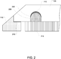
- the electronic device 100 may be, for example, a tablet device (as illustrated), a mobile phone, a portable computer, a wearable device, and so on.
- the ceramic layer 105 may abut a housing 115.
- the ceramic layer 105 may be adjacent to, bonded to and/or directly abutting the housing 115.
- the electronic device 100 is shown with the cover glass 105 proud of the housing 115.
- the cover glass may be flush with, or recessed within, the housing.
- the cover glass is shown with a flat upper surface and an angled sidewall. In other embodiments, the upper surface may be curved or otherwise arcuate rather than planar, and the arc may continue along the cover glass such that no sharp angle with any sidewall is formed.
- the cover glass 105 overlaying the display may be made of a transparent ceramic such as sapphire. It should be appreciated that the cover glass 105 may be fully or at least partially formed from other materials such as alumina, chemically strengthened glass, and the like. For example, a layer of alumina may be used to bond two adjacent sapphire layers to one another. Likewise, an optically clear adhesive may be used to bond adjacent sapphire layers and may form part of the cover glass.
- cover glass may be used herein, it should be appreciated that this term imposes no requirement that glass be incorporated or used in the element. For example, a cover glass may be formed entirely from sapphire, or may be formed from sapphire and alumina, sapphire and adhesive, and so forth.
- the terms “cover glass” and “ceramic layer” may be used essentially interchangeably, certain embodiments of a “ceramic layer” may be replaced with (or encompass) non-ceramics, such as glass, plastic and so on.
- a sample electronic component 110 is shown embedded within the cover glass 105.
- the electronic element may be visible through the ceramic in certain embodiments and as shown.
- the electronic element 110 may be placed beneath an ink layer or otherwise concealed so that it is not visible through the cover glass.
- the cover glass 105 may be opaque or translucent, at least in part, in order to conceal the electronic element.
- the electronic element may be formed from a transparent or translucent material.
- the electronic component 110 may include, incorporate, or be one or more antennas.
- a first portion of the electronic component may be an antenna and a second portion may be a ground path.
- the multiple electronic antennas may be physically and/or operationally connected to one another.
- Fig. 2 depicts a first sample cross-section taken along line A-A of Fig. 1 .
- a trench 200 may be formed in the sapphire or other ceramic material forming the cover glass 105.
- the trench 200 may run about all four sides of the cover glass to form an annular groove, or may be discontinuous, such that multiple trench segments are formed as part of the overall trench.
- the trench 200 may be formed through a variety of different operations.
- the trench may be formed by computer numerical control (CNC) grinding, ultrasonic machining, laser ablation, plasma etching, laser etching (in addition to or without chemical etching), deep reactive ion etching, and so forth.
- CNC computer numerical control
- the laser may be a femtosecond laser or any other suitable laser.
- the electronic component 110 may be deposited in the trench 200, filling at least a portion of the trench.
- the component may be pre-formed prior to deposit, or may be deposited in a liquid form and cool within the trench. Further, the electronic component 110 may extend the length of the trench 200 or may extend only partially along the trench. Likewise, as mentioned above, multiple electronic components may occupy a single trench and may be laid out without touching one another or may be laid out to at least partially overlap.
- the electronic component 110 may be a conductive metal strip extending along at least a portion of the trench 200.
- the metal may be heated until it is a liquid and poured into the trench; upon cooling, the liquid will generally occupy the deepest part of the trench.
- the ceramic structure 105 may be inverted from its orientation shown in Fig. 2 during addition of the electronic component 110, such that the deepest part during addition of the electronic component is the "top" of the trench with respect to the orientation shown in Fig. 2 .
- the electronic component 110 may be deposited within the trench 200 through chemical vapor deposition or any other suitable deposition method. This may permit the bottom or walls of the trench 200 to be coated with the electronic component without requiring the center of the trench to be filled, for example and as shown in Fig. 2 .
- the filler material 205 may be sapphire, alumina, glass (which may or may not be chemically strengthened), plastic, epoxy, poly(methyl methacrylate) (PMMA), polycarbonate, or the like, and may depend on the material forming the ceramic substrate.
- the filler 205 has an index of refraction and transparency that is close or identical to that of the ceramic.
- alumina may be employed as a filler 205 in order to match the optical properties of sapphire.
- a solid piece of ceramic may be used as a filler 205.
- the ceramic filler may have a size and shape that approximately matches the dimensions of the trench 200.
- This ceramic filler 205 may be bonded to the ceramic material forming the cover glass 105, for example along the sides of the trench 200 or at any other region of the trench not filled by the electronic component 110.
- an optically clear adhesive may be used to bond the two.
- a frit may be placed between the ceramic 105 and filler 205 and heated to bond the two.
- amorphous alumina or glass may be placed between the ceramic substrate and ceramic filler and heated to fuse the two together, for example at a molecular level.
- an adhesive other than an optically clear adhesive may be employed.
- an epoxy may bond the ceramic filler and the ceramic substrate. Fillers may be used with any or all embodiments discussed herein.
- one or more through-holes may be formed when filling the trench 200. These vias may be formed by leaving certain portions of the trench 200 unfilled, or by removing some of the filler 205.
- the vias may permit electrical connection from the electronic component embedded within the trench to one or more electrical elements 210 within the housing.
- a via may electrically connect the embedded electronic component to a power supply, a processor, a sensor, an electrical ground, and the like.
- Electronic circuitry 210 may likewise or further include a display stack that is viewable through the cover glass 105.
- the display stack may generate graphics, text and/or other images that may be shown to a viewer of the electronic device 100.
- the display stack may be an LCD display stack, and LED display stack, an OLED display stack, and so on.
- the display stack may include a number of discrete elements or layers, including color filters, polarizers, lighting elements (such as back lights and/or edge lights), a pixel layer, TFT circuitry for driving pixels, and the like.
- the display stack may also include touch-sensitive circuitry configured to recognize a touch on the cover glass 105 or elsewhere on the housing 115 of the device 100.
- One example of such circuitry is a capacitive touch sensor array.
- a biometric sensor such as a capacitive fingerprint sensor
- multiple vias may extend through the filler in order to permit multiple electrical connections. This may be useful if there are multiple electronic components located within the trench, for example. It may also be useful if an electronic component requires more than one type of electrical connection (for example, some electronic components may require both power and an output connection).
- the resulting structure may be polished and finished.
- the exact method used to polish the ceramic and filler may vary with certain properties of the two, end uses of the cover glass (or other surface) formed by the combination of ceramic and filler, visibility of the back side of the ceramic and interface between ceramic and filler, and the like.
- the interface between ceramic and filler may be smoother and/or more polished than in embodiments where the ceramic is translucent or opaque, and/or embodiments where the ceramic is not an external portion of the electronic device.
- the back surface of the ceramic (e.g., the surface of the ceramic on which the trench is formed) and/or the filler may be polished through annealing, mechanical polishing, chemical etching, aero lapping, and the like.
- annealing may serve to at least partially bond the ceramic to the filler through its high heat of operation.
- an adhesive 215 may bond the cover glass 105 to the housing 115. This adhesive may prevent ingress of particles from the environment to the interior of the electronic device 100.
- the adhesive 215 may be replaced with a barrier that may be affixed or adhered to either or both of the housing and cover glass. The barrier may be compressible in certain embodiments in order to provide a tight seal between the cover glass 105 and housing 115.
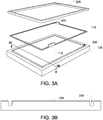
- Fig. 3A is an exploded view of a ceramic substrate 105 (e.g., a cover glass), an electronic element 110 (such as an antenna), and a filler 205.
- the trench 200 is shown on the underside of the ceramic substrate, which may be an optically transparent ceramic such as sapphire.
- the trench 200 is generally sized to receive the electronic element 110.
- the electronic component does not extend past any edge of the trench, but instead is fully contained within the trench.
- Fig. 3A depicts a single electronic component that is formed as a contiguous, unbroken rectangle, it should be appreciated that differently-shaped or configured electronic components may be employed.
- multiple electronic components may be separated by one or more insulating spacers.
- the size and shape of the electronic component 110 may vary somewhat from the size and shape of the trench 200, even though the electronic component may fit fully within the trench.
- the multiple electronic components may not be physically joined to one another or a single electronic component may be placed within the trench.
- the filler 205 is also shown in Fig. 3A .
- the filler is shown as a solid annular construct in Fig. 3A , it should be appreciated that it may be granular, discontinuous, or otherwise formed from multiple pieces or parts.
- the filler 205 bonds to the ceramic substrate 105 and retains the electronic component 110 in place in the trench 200.
- the filler may also serve to electrically isolate or insulate the electronic component from other electronic elements within the device enclosure.
- the filler 205 may be chosen for its electrically insulating properties; for example, a material with a high dielectric constant may be chosen as a filler.
- One or more depressions or recesses 300 may be formed in the filler to accommodate one or more protrusions 112 of the antenna, as indicated in phantom in Fig. 3A .
- Fig. 3B generally is a cross-sectional view taken along line 3B-3B of Fig. 3A , showing the cross-sectional structure of the trench 200 in the ceramic substrate 105. It should be appreciated that the cross-sectional structure of the trench may vary between embodiments. For example, the trench may have a flat or angled bottom rather than a curved bottom.
- Fig. 4 depicts a cross-sectional view of another embodiment 400, again taken along line A-A of Fig. 1 .
- Fig. 4 generally depicts a cross-section of a cover glass 105 formed from multiple laminated layers of sapphire 405, 410, or another suitable cover glass material.
- a receptacle, such as a trench 200, may be formed in one of the sapphire layers and may hold the antenna or antennas.
- the cover glass 105 may be formed from first 405 and second 410 cover glass layers that are bonded together.
- the first, outer layer 405 may have a depression 420 formed in its inner surface that is sized to accept the second, inner cover glass layer (see, for example, Fig. 5B ).
- the outer layer 405 may be somewhat similar to a bucket- it may have a raised ledge or lip 425 running along its periphery, with the raised ledge extending inwardly into the outer layer.
- the raised ledge 425 may abut a base 430 of the depression 420, thus forming a wall or walls around the depression.
- the ledge may be formed by multiple sidewalls abutting one another.
- the sidewalls may meet at a sharp angle, such as a right angle, or may curved transitions may be formed between the sidewalls and connect the sidewalls. Likewise, the transition from the sidewall(s) to the base may be curved, sharp, angled, or the like.
- the second, inner cover glass layer 410 may be sized to fit within, and substantially fill, the depression 420 in the outer cover glass layer 405. Accordingly, the shape of the inner cover glass layer may be at least partially dictated by the shape of the depression 420 in the outer cover glass layer. In some embodiments, however, a spacer, filler or the like may be placed between the inner and outer cover glass layers.
- a trough or groove 200 may be formed in an upper surface of the inner cover glass layer 410, as shown in Fig. 4 .
- the antenna or other electronic component 110 may be formed in or placed in this groove prior to sealing the outer and inner cover glass layer.
- it may be relatively simple to place or form the antenna 110 within the embodiment 400, since the upper surface of the inner cover glass layer 405 is exposed prior to bonding together the inner and outer cover glass layers.
- the antenna may be solid and placed within the trough 200, may be deposited in vapor or particulate form into the trough, may be poured as a liquid into the trough (after which it may cool to form a solid), and so on.
- the antenna when placed, may occupy the entirety of the trough in some embodiments, although in other embodiments the antenna may occupy only a portion of the trough.
- the occupied portion may be only a segment of the length of the trough, or may be a partial depth of the trough, or both.
- the relative thicknesses of the outer and inner cover glass layers 405, 410 may vary from embodiment to embodiment. They need not be the same thickness at any point or along any cross-section.
- the exact location of the trough 200 may vary. It may be formed at any point along the inner cover glass layer 405 and may (or may not) extend fully around a perimeter of the cover glass layer 410. The distance between an edge of the inner cover glass layer and the edge of the trough may vary as necessary or desired and need not be constant. Further, in some embodiments the trough 200 may be formed in the depression 420 of the outer cover glass layer 405 rather than in the inner cover glass layer 410.
- the inner and outer cover glass layers 405, 410 may be bonded to one another with a chemical or mechanical bond, or any other suitable adhesive bond employing any suitable material including alumina, an adhesive (such as an optically clear adhesive), and the like.
- one or more vias 415 may connect the antenna or other electronic component 110 to the electronic circuitry 210 of the electronic device 400.
- the vias 415 may be formed in the cover glass layer 410 in any of a number of fashions and may be filled with any suitable conductive material, including metal, ceramic, composites, and the like.
- the size and/or shape of the vias 415 may vary not only from embodiment to embodiment, but also between vias of the same embodiment. Certain vias may be lozenge-shaped while others are round, for example.
- the via-filling material may be overmolded or overfill the via in some embodiments.
- an end of the via 415 may be larger than a middle portion of the via to provide a larger contact surface to either the antenna or the electronic circuitry 210.
- the cross-section of the via may vary along its length in some embodiments.
- the vias 415 may be formed by a similar or identical process as used to form the antenna 110, for example physical vapor deposition.
- the vias may be formed in a separate deposition process, for example after the antenna is formed and after the inner and outer cover glass layers 405, 410 are bonded to one another.
- the vias 415 may be flooded with a liquid metal, which may then dry to fill the vias and form electrical connections to the antenna(s).
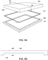
- Fig. 5A generally shows an exploded view of the outer cover glass layer 405, the antenna 110, and the inner cover glass layer 410.
- one or more holes may be formed in the outer cover glass layer to accept one or more protrusions of the antenna.
- the protrusions if any project downward, such holes may be formed in the inner cover glass layer 410 and may be formed as deeper sections of the trough 200.
- Fig. 5B is a cross-sectional view taken along line 5B-5B of Fig. 5A.
- Fig. 5B illustrates the "bucket" shape of the depression 420 as formed by the sidewalls 425 and base 430.
- Fig. 6 shows another embodiment 600 of an electronic device having an electronic component 110 embedded in a cover glass 105.
- the cover glass may be formed from a ceramic, one example of which is sapphire.
- Fig. 6 is generally similar to Fig. 4 except that the trough 200 containing the antenna 110 is formed in the outer cover glass layer 605. Although no via is shown in Fig. 6 , vias may extend through the inner cover glass layer 610 from the electronic circuitry 210 to the antenna 110. Placing the via closer to an exterior surface of the cover glass1 05 and further from the electronic circuitry 210 may improve operation of the antenna and may prevent or reduce cross-talk and/or other interference between the antenna and the electronic circuitry.
- Fig. 7 depicts a cross-sectional view similar to those of Figs. 4 and 6 , showing yet another embodiment 700 having an antenna 110 embedded in a ceramic material.
- the antenna may be formed or placed within a slot or groove 705 that runs about an exterior edge 710 of the cover glass 105.
- the antenna edge may be exposed to the environment while in other a coating may be applied over the antenna's edge and, optionally, at least part of the edge of the cover glass and/or housing to provide shielding from environmental effects and hazards.
- the groove/slot 705 may be formed at any time, such as before or after the inner and outer ceramic layers 715, 720 are affixed to one another. Some embodiments may use a single sheet of ceramic rather than the inner and outer layers depicted in Fig. 7 .
- Fig. 8 is another cross-sectional view of an embodiment 800 similar to that of Fig. 7 .
- the cover glass 105 is split into upper and lower cover glass layers 805, 810.
- the layers are not nested together as is the case in the embodiments shown in Figs. 4 and 6 . Rather, the layers form the upper and lower portions of the cover glass and sit adjacent to one another with an interface 815 defining the point of contact.
- the interface 815 may be planar, such that the opposing sides of the upper and lower cover glass layers are flat.
- the layers may be bonded to one another, for example with an optically clear adhesive.
- the slot 820 for the antenna 110 may be formed in either of the upper and lower cover glass layers 805, 810 or may be partially in both layers, although the slot is shown in Fig. 7 in the upper cover glass layer. Likewise, the slot 820 need not necessarily be formed in either layer adjacent the interface 815 between the layers. It may be more convenient and/or simpler to create the slot at the interface, however, since the slot may then be formed in an exposed surface of at least one of the cover glass layers prior to bonding the two together. Again, one or more vias may extend through the lower cover glass layer 810 and connect the antenna to the electronic circuitry.
- Fig. 9 is another cross-sectional view of an embodiment 900 similar to that of Figs. 7 and 8 .
- the cover glass 105 is split into upper and lower cover glass layers 905 and 910.
- the layers may be bonded to one another, for example with an optically clear adhesive.
- the slot, groove or other aperture 920 for the antenna 110 may be formed in either of the upper and lower cover glass layers 905, 910 or may be partially in both layers, although the slot is shown in Fig. 9 in the upper cover glass layer 105.
- the slot 920 need not necessarily be formed in either layer adjacent the interface 915 between the layers. It may be more convenient and/or simpler to create the slot at the interface, however, since the slot may then be formed in an exposed surface of at least one of the cover glass layers prior to bonding the two together.
- one or more vias may extend through the lower cover glass layer 910 and connect the antenna to the electronic circuitry. The one or more vias may extend through a portion of the upper cover glass layer 905 for embodiments in which the slot 920 is not formed entirely within the upper cover glass layer 905.
- the electronic circuitry may include a display stack 250 that is viewable through the cover glass 905.
- the display stack may generate graphics, text and/or other images via an LCD display stack, and LED display stack, an OLED display stack, or any other suitable display stack.
- the display stack may include a number of discrete elements or layers, including color filters, polarizers, lighting elements (such as back lights and/or edge lights), a pixel layer, TFT circuitry for driving pixels, and the like.
- the display stack may also be positioned below touch-sensitive circuitry 240 configured to recognize a touch on the cover glass 105 or elsewhere on the housing of the device 900.
- touch-sensitive circuitry is a capacitive touch sensor array.
- the touch-sensitive circuitry may take the form of a layer either located above the display (with respect to the orientation shown in FIG. 9 ) or in-plane with the pixels of the display.
- a biometric sensor such as a capacitive fingerprint sensor
- a force-sensitive sensors may be incorporated into the electronic circuitry, as may one or more force-sensitive sensors.
- the electronic circuitry may include other elements.
- the electronic circuitry may include a wireless communication element 260 separate from the antenna 110.
- a wireless communication element 260 may be a Bluetooth element, a Wi-Fi element, a near-field communication element, or other radio frequency elements. Such a communication element may be placed below the display, as shown in FIG. 9 .
- the electronic device may also include a sensor 230 positioned below the electronic circuitry.
- the sensor 930 may be any number of different sensor types.
- the sensor 930 may be a motion or orientation sensor such as a gyroscopic sensor or accelerometer.
- the sensor 930 may be an optical sensor such as an ambient light sensor.
- An optical sensor may be positioned and oriented to receive and measure external light through the upper and lower cover glass layers 905 and 910 and the electronic circuitry 210, including touch-sensitive circuitry 240, display stack 250, and/or wireless communication element 260, as shown in FIG. 9 .
- An optical sensor may be an ambient light sensor, a color sensor, a proximity sensor, or other suitable optical sensor.
- the electronic circuitry 210 may be at least partially optically clear.
- electronic circuitry 210 may include an aperture positioned above the sensor 930.
- the optical sensor may receive ambient light transmitted through the cover glass and between pixels of the display
- one or more ink layers may be deposited beneath at least a portion of the cover glass to provide decoration and/or to mask the presence of the antenna.
- the region of the cover glass beneath the antenna may be colored to obscure the antenna, for example.
- Such ink layers are purely optional.
- the ink may be selectively deposited so as to not cover the vias, thereby permitting electrical connections between the antenna(s) and the electronic circuitry through the vias.
- Some embodiments may have a trench or passage formed entirely within a cover glass.
- a laser may be used to selectively excite ceramic molecules at a certain depth beneath the surface of the cover glass. These excited molecules may vaporize while the molecules surrounding them may remain relatively stable and unaffected.
- a void may be formed in the interior of the cover glass without requiring any through-holes to be formed or any chemicals to be used. Vias may later be formed to connect to the void; these vias may permit the antenna material to be deposited within the void as necessary. The vias may then be filled or sealed with an appropriate material.
- the laser may be selectively applied to the sapphire lattice at a depth within cover glass to weaken the bonds between molecules.
- These molecules with weakened bonds may then be more easily etched with a chemical etchant to form a passage or path through the sapphire, into which an antenna or other electronic component may be deposited. Vias may be formed in the same fashion and, optionally, in conjunction with forming the internal trench.
- a shield may be placed between the electronic component and the electronic circuitry.
- a shield may likewise be placed therebetween.
- the shield may insulate the electronic component in the cover glass from noise, parasitic capacitances and other undesirable electrical effects caused by proximity to the electronic circuitry and vice versa.
- the shield may be a ground plane.
- the ink if used may be deposited on the shield itself and the shield may additionally provide structural support to the cover glass.
Landscapes
- Engineering & Computer Science (AREA)
- Computer Hardware Design (AREA)
- General Engineering & Computer Science (AREA)
- Theoretical Computer Science (AREA)
- Human Computer Interaction (AREA)
- Physics & Mathematics (AREA)
- General Physics & Mathematics (AREA)
- Computer Networks & Wireless Communication (AREA)
- Casings For Electric Apparatus (AREA)
- Devices For Indicating Variable Information By Combining Individual Elements (AREA)
- Details Of Aerials (AREA)
- Telephone Set Structure (AREA)
Claims (9)
- Un dispositif électronique (100), comprenant :un boitier (115),un afficheur (250) dans le boitier (115) ;une vitre de protection (105) qui recouvre l'afficheur etqui est solidarisée au boitier (115), la vitre de protection (105) ayant une première et une seconde surface opposées et la première surface de la vitre de protection formant une surface extérieure du dispositif électronique ;une antenne (110) ; etun circuit électronique (210) à l'intérieur du boitier ;caractérisé par :un sillon (200) dans la seconde surface de la vitre de protection, au moins une partie de l'antenne étant formée dans le sillon (200) ;de l'encre qui est formée sur la seconde surface de la vitre de protection (105) dans le sillon (200), l'encre étant interposée entre la seconde surface de la vitre de protection (105) et l'antenne (110) ;dans lequel le circuit électronique (210) est en communication électrique avec l'antenne (110) ; etun élément de retenue dans le sillon, la au moins une partie de l'antenne étant interposée entre l'élément de retenue et l'encre dans le sillon.
- Le dispositif électronique (100) de la revendication 1, dans lequel :
l'élément de retenue occupe un reste du sillon (200), noyant ainsi l'antenne (110) avec la vitre de protection (105) . - Le dispositif électronique (100) de l'une ou l'autre des revendications 1 ou 2, dans lequel l'élément de retenue est formé de l'un parmi : saphir ou alumine.
- Le dispositif électronique (100) de l'une ou l'autre des revendications 2 ou 3, dans lequel l'élément de retenue est en liaison moléculaire avec la vitre de protection (105).
- Le dispositif électronique (100) de l'une des revendications 2 à 4, dans lequel l'élément de retenue est une fritte qui après dépôt dans le sillon (200) est fondue avec.
- Le dispositif électronique (100) de l'une des revendications précédentes, comprenant en outre :
au moins un via (415) en communication électrique avec le circuit électronique (210) et l'antenne (110), le via (415) définissant une connexion électrique entre le circuit électronique (210) et l'antenne (110). - Le dispositif électronique (100) de la revendication 6, dans lequel le via (415) s'étend au travers d'une partie de la vitre de protection (105).
- Le dispositif électronique (100) de l'une des revendications précédentes, dans lequel l'afficheur (250) comprend un empilement d'afficheurs fonctionnels pour afficher au moins une image au travers de la vitre de protection (105).
- Le dispositif électronique (100) de l'une des revendications précédentes, comprenant en outre un capteur (930) disposé au-dessous du circuit électronique (210) .
Applications Claiming Priority (3)
| Application Number | Priority Date | Filing Date | Title |
|---|---|---|---|
| US14/033,981 US9632537B2 (en) | 2013-09-23 | 2013-09-23 | Electronic component embedded in ceramic material |
| US201361892389P | 2013-10-17 | 2013-10-17 | |
| PCT/US2014/056439 WO2015042335A1 (fr) | 2013-09-23 | 2014-09-19 | Composant électronique intégré dans un matériau céramique |
Publications (2)
| Publication Number | Publication Date |
|---|---|
| EP3014380A1 EP3014380A1 (fr) | 2016-05-04 |
| EP3014380B1 true EP3014380B1 (fr) | 2019-07-17 |
Family
ID=51688413
Family Applications (1)
| Application Number | Title | Priority Date | Filing Date |
|---|---|---|---|
| EP14781994.0A Active EP3014380B1 (fr) | 2013-09-23 | 2014-09-19 | Composant électronique intégré dans un matériau céramique |
Country Status (7)
| Country | Link |
|---|---|
| EP (1) | EP3014380B1 (fr) |
| JP (1) | JP6636432B2 (fr) |
| KR (1) | KR101933285B1 (fr) |
| CN (2) | CN204305488U (fr) |
| AU (1) | AU2014323434B2 (fr) |
| TW (1) | TWI618465B (fr) |
| WO (1) | WO2015042335A1 (fr) |
Families Citing this family (14)
| Publication number | Priority date | Publication date | Assignee | Title |
|---|---|---|---|---|
| KR102399741B1 (ko) * | 2015-05-22 | 2022-05-20 | 삼성전자주식회사 | 디스플레이 모듈 및 그 제조 방법 |
| WO2017008247A1 (fr) * | 2015-07-14 | 2017-01-19 | 华为技术有限公司 | Terminal mobile |
| EP3347162A4 (fr) * | 2015-09-08 | 2019-05-15 | 3M Innovative Properties Company | Outil rotatif abrasif souple |
| US9792516B2 (en) * | 2016-01-26 | 2017-10-17 | Next Biometrics Group Asa | Flexible card with fingerprint sensor |
| CN106790827B (zh) * | 2017-01-24 | 2024-02-13 | 北京小米移动软件有限公司 | 陶瓷壳体组件及其加工工艺、电子设备 |
| CN115686136A (zh) * | 2017-03-29 | 2023-02-03 | 苹果公司 | 具有集成接口系统的设备 |
| JP6944169B2 (ja) * | 2017-04-25 | 2021-10-06 | 株式会社Nsc | ディスプレイ用保護カバー |
| US10292286B2 (en) | 2017-07-31 | 2019-05-14 | Apple Inc. | Patterned glass layers in electronic devices |
| KR102330968B1 (ko) | 2018-01-15 | 2021-12-01 | 도판 인사츠 가부시키가이샤 | 전자 기기 |
| US20200021905A1 (en) | 2018-07-10 | 2020-01-16 | New Audio LLC | Wireless earpiece having antenna with wall-embedded radiating element and related technology |
| CN114204255A (zh) * | 2019-01-09 | 2022-03-18 | 华为技术有限公司 | 一种终端设备 |
| CN110519953A (zh) * | 2019-07-27 | 2019-11-29 | 南昌欧菲光科技有限公司 | 电子设备及其盖板 |
| US11448801B2 (en) | 2019-07-30 | 2022-09-20 | Apple Inc. | Textured glass layers in electronic devices |
| TWI734511B (zh) * | 2020-06-05 | 2021-07-21 | 元璋玻璃股份有限公司 | 玻璃通訊天線及其製造方法 |
Citations (9)
| Publication number | Priority date | Publication date | Assignee | Title |
|---|---|---|---|---|
| US20080192014A1 (en) * | 2007-02-08 | 2008-08-14 | Tyco Electronics Corporation | Touch screen using carbon nanotube electrodes |
| US20100311356A1 (en) * | 2009-06-09 | 2010-12-09 | Ahmadreza Rofougaran | Method and system for a touchscreen interface utilizing leaky wave antennas |
| US20110001420A1 (en) * | 2007-11-22 | 2011-01-06 | Saint-Gobain Glass France | Substrate bearing an electrode, organic light-emitting device incorporating it, and its manufacture |
| WO2011137861A2 (fr) * | 2011-07-01 | 2011-11-10 | 华为终端有限公司 | Terminal et procédé de fabrication d'un écran tactile de terminal |
| CN202217780U (zh) * | 2011-08-29 | 2012-05-09 | 东莞宇龙通信科技有限公司 | 一种用于近距离无线通讯的天线及移动终端 |
| US20120212890A1 (en) * | 2011-02-22 | 2012-08-23 | Hironari Hoshino | Cover and electronic device |
| US20120299841A1 (en) * | 2011-05-27 | 2012-11-29 | Auden Techno Corp. | Touch structure and touch panel having an antenna function |
| DE102011076756A1 (de) * | 2011-05-31 | 2012-12-06 | Schott Ag | Substratelement für die Beschichtung mit einer Easy-to-clean Beschichtung |
| US20130000829A1 (en) * | 2010-03-17 | 2013-01-03 | Hanita Coatings R.C.A. Ltd | Polymeric substrate with laminated glass layer |
Family Cites Families (22)
| Publication number | Priority date | Publication date | Assignee | Title |
|---|---|---|---|---|
| JPS63196106U (fr) | 1987-01-20 | 1988-12-16 | ||
| JPH0718167Y2 (ja) * | 1991-11-29 | 1995-04-26 | セントラル硝子株式会社 | 合わせガラス |
| GB2373952B (en) * | 2000-12-29 | 2004-10-27 | Nokia Mobile Phones Ltd | A casing |
| US6677906B2 (en) * | 2002-04-17 | 2004-01-13 | Dell Products L.P. | Glass antenna for laptop computers |
| KR101176027B1 (ko) * | 2004-10-19 | 2012-08-24 | 가부시키가이샤 한도오따이 에네루기 켄큐쇼 | 안테나를 구비한 반도체장치 및 그 제조 방법 |
| EP1653554B1 (fr) * | 2004-11-01 | 2007-12-12 | Asahi Glass Company, Limited | Vitrage feuilleté avec antenne encastrée et son procédé de préparation |
| US8350766B2 (en) * | 2004-11-01 | 2013-01-08 | Asahi Glass Company, Limited | Antenna-embedded laminated glass |
| KR101025054B1 (ko) * | 2005-04-01 | 2011-03-25 | 니폰샤신인사츠가부시키가이샤 | 디스플레이용 투명 안테나 및 안테나 부착 디스플레이용투광성 부재 및 안테나 부착 하우징용 부품 |
| JP5026163B2 (ja) * | 2007-06-26 | 2012-09-12 | セイコーインスツル株式会社 | 電子機器 |
| JP2009103833A (ja) * | 2007-10-22 | 2009-05-14 | Sharp Corp | 表示装置 |
| US8629841B2 (en) * | 2008-04-30 | 2014-01-14 | Apple Inc. | Multi-touch sensor patterns and stack-ups |
| FR2940872B1 (fr) * | 2009-01-07 | 2012-05-18 | Commissariat Energie Atomique | Ecran plat avec antenne integree |
| US20100321325A1 (en) * | 2009-06-17 | 2010-12-23 | Springer Gregory A | Touch and display panel antennas |
| JP2011109407A (ja) * | 2009-11-17 | 2011-06-02 | Funai Electric Co Ltd | 携帯情報通信端末 |
| US8345410B2 (en) * | 2010-01-06 | 2013-01-01 | Apple Inc. | Handheld computing device |
| US8766858B2 (en) * | 2010-08-27 | 2014-07-01 | Apple Inc. | Antennas mounted under dielectric plates |
| US20130079139A1 (en) * | 2011-09-26 | 2013-03-28 | Wacom Co., Ltd. | Overlays for touch sensitive screens to simulate buttons or other visually or tactually discernible areas |
| US9937526B2 (en) * | 2011-09-30 | 2018-04-10 | Apple Inc. | Antenna structures with molded and coated substrates |
| WO2013137158A1 (fr) * | 2012-03-14 | 2013-09-19 | 旭硝子株式会社 | Matériau de surface transparent avec couche adhésive, dispositif d'affichage et procédé de fabrication associé |
| TW201342246A (zh) * | 2012-04-02 | 2013-10-16 | Nuvoton Technology Corp | 電子裝置 |
| CN102749771B (zh) * | 2012-04-06 | 2015-02-04 | 信利工业(汕尾)有限公司 | 一种集成nfc天线的薄膜晶体管显示器 |
| JP5988361B2 (ja) * | 2012-07-27 | 2016-09-07 | 京セラ株式会社 | 電子機器 |
-
2014
- 2014-09-19 EP EP14781994.0A patent/EP3014380B1/fr active Active
- 2014-09-19 WO PCT/US2014/056439 patent/WO2015042335A1/fr not_active Ceased
- 2014-09-19 JP JP2016544001A patent/JP6636432B2/ja active Active
- 2014-09-19 AU AU2014323434A patent/AU2014323434B2/en active Active
- 2014-09-19 KR KR1020167008567A patent/KR101933285B1/ko active Active
- 2014-09-23 CN CN201420688579.0U patent/CN204305488U/zh not_active Expired - Fee Related
- 2014-09-23 CN CN201410649044.7A patent/CN104582359B/zh active Active
- 2014-09-23 TW TW103132852A patent/TWI618465B/zh active
Patent Citations (10)
| Publication number | Priority date | Publication date | Assignee | Title |
|---|---|---|---|---|
| US20080192014A1 (en) * | 2007-02-08 | 2008-08-14 | Tyco Electronics Corporation | Touch screen using carbon nanotube electrodes |
| US20110001420A1 (en) * | 2007-11-22 | 2011-01-06 | Saint-Gobain Glass France | Substrate bearing an electrode, organic light-emitting device incorporating it, and its manufacture |
| US20100311356A1 (en) * | 2009-06-09 | 2010-12-09 | Ahmadreza Rofougaran | Method and system for a touchscreen interface utilizing leaky wave antennas |
| US20130000829A1 (en) * | 2010-03-17 | 2013-01-03 | Hanita Coatings R.C.A. Ltd | Polymeric substrate with laminated glass layer |
| US20120212890A1 (en) * | 2011-02-22 | 2012-08-23 | Hironari Hoshino | Cover and electronic device |
| US20120299841A1 (en) * | 2011-05-27 | 2012-11-29 | Auden Techno Corp. | Touch structure and touch panel having an antenna function |
| DE102011076756A1 (de) * | 2011-05-31 | 2012-12-06 | Schott Ag | Substratelement für die Beschichtung mit einer Easy-to-clean Beschichtung |
| US20150152558A1 (en) * | 2011-05-31 | 2015-06-04 | Schott Ag | Substrate element for coating with an easy-to-clean coating |
| WO2011137861A2 (fr) * | 2011-07-01 | 2011-11-10 | 华为终端有限公司 | Terminal et procédé de fabrication d'un écran tactile de terminal |
| CN202217780U (zh) * | 2011-08-29 | 2012-05-09 | 东莞宇龙通信科技有限公司 | 一种用于近距离无线通讯的天线及移动终端 |
Also Published As
| Publication number | Publication date |
|---|---|
| CN104582359A (zh) | 2015-04-29 |
| TWI618465B (zh) | 2018-03-11 |
| AU2014323434B2 (en) | 2017-07-13 |
| KR101933285B1 (ko) | 2018-12-27 |
| WO2015042335A1 (fr) | 2015-03-26 |
| KR20160047579A (ko) | 2016-05-02 |
| AU2014323434A1 (en) | 2016-02-11 |
| CN204305488U (zh) | 2015-04-29 |
| JP6636432B2 (ja) | 2020-01-29 |
| TW201528912A (zh) | 2015-07-16 |
| EP3014380A1 (fr) | 2016-05-04 |
| CN104582359B (zh) | 2017-12-01 |
| JP2016540257A (ja) | 2016-12-22 |
Similar Documents
| Publication | Publication Date | Title |
|---|---|---|
| US9678540B2 (en) | Electronic component embedded in ceramic material | |
| US9632537B2 (en) | Electronic component embedded in ceramic material | |
| EP3014380B1 (fr) | Composant électronique intégré dans un matériau céramique | |
| CN111384101B (zh) | 柔性显示设备和包括柔性显示设备的电子装置 | |
| TWI576734B (zh) | 觸控裝置 | |
| KR101758187B1 (ko) | 터치제어장치 | |
| US9772730B2 (en) | Touch panel with function of fingerprint identification | |
| US8887425B2 (en) | Display device and method for manufacturing the same | |
| US9058154B2 (en) | Window substrate and display device having the same | |
| CN203982334U (zh) | 具有指纹识别功能的触控面板 | |
| KR20140127735A (ko) | 도전성 필름, 도전성 필름 제조 방법, 및 도전성 필름을 구비하는 터치 스크린 | |
| TW201538904A (zh) | 將彩色濾光片整合於反射式顯示器之前光源 | |
| KR101665906B1 (ko) | 도전성 필름, 도전성 필름 제조 방법, 및 도전성 필름을 구비하는 터치 스크린 | |
| JP2010128648A (ja) | 入力装置およびその製造方法 | |
| TW201527112A (zh) | 顯示裝置 | |
| KR20220073491A (ko) | 하우징을 포함하는 전자 장치 및 하우징의 제조 방법 | |
| JP6706760B2 (ja) | タッチセンサおよび電子機器 | |
| US20090309845A1 (en) | Touch window | |
| TW201546675A (zh) | 觸控顯示面板之模組結構 | |
| CN119907407A (zh) | 显示面板及显示装置 | |
| KR20140135484A (ko) | 모바일 장치용 지문 센서 모듈 및 이의 제조 방법 |
Legal Events
| Date | Code | Title | Description |
|---|---|---|---|
| PUAI | Public reference made under article 153(3) epc to a published international application that has entered the european phase |
Free format text: ORIGINAL CODE: 0009012 |
|
| 17P | Request for examination filed |
Effective date: 20160129 |
|
| AK | Designated contracting states |
Kind code of ref document: A1 Designated state(s): AL AT BE BG CH CY CZ DE DK EE ES FI FR GB GR HR HU IE IS IT LI LT LU LV MC MK MT NL NO PL PT RO RS SE SI SK SM TR |
|
| AX | Request for extension of the european patent |
Extension state: BA ME |
|
| DAX | Request for extension of the european patent (deleted) | ||
| STAA | Information on the status of an ep patent application or granted ep patent |
Free format text: STATUS: EXAMINATION IS IN PROGRESS |
|
| 17Q | First examination report despatched |
Effective date: 20170724 |
|
| RAP1 | Party data changed (applicant data changed or rights of an application transferred) |
Owner name: APPLE INC. |
|
| RIC1 | Information provided on ipc code assigned before grant |
Ipc: G06F 1/16 20060101AFI20181210BHEP Ipc: H01Q 1/40 20060101ALI20181210BHEP Ipc: H01Q 1/22 20060101ALI20181210BHEP Ipc: H01Q 1/24 20060101ALI20181210BHEP |
|
| GRAP | Despatch of communication of intention to grant a patent |
Free format text: ORIGINAL CODE: EPIDOSNIGR1 |
|
| STAA | Information on the status of an ep patent application or granted ep patent |
Free format text: STATUS: GRANT OF PATENT IS INTENDED |
|
| INTG | Intention to grant announced |
Effective date: 20190205 |
|
| GRAS | Grant fee paid |
Free format text: ORIGINAL CODE: EPIDOSNIGR3 |
|
| GRAA | (expected) grant |
Free format text: ORIGINAL CODE: 0009210 |
|
| STAA | Information on the status of an ep patent application or granted ep patent |
Free format text: STATUS: THE PATENT HAS BEEN GRANTED |
|
| AK | Designated contracting states |
Kind code of ref document: B1 Designated state(s): AL AT BE BG CH CY CZ DE DK EE ES FI FR GB GR HR HU IE IS IT LI LT LU LV MC MK MT NL NO PL PT RO RS SE SI SK SM TR |
|
| REG | Reference to a national code |
Ref country code: GB Ref legal event code: FG4D |
|
| REG | Reference to a national code |
Ref country code: CH Ref legal event code: EP |
|
| REG | Reference to a national code |
Ref country code: DE Ref legal event code: R096 Ref document number: 602014050181 Country of ref document: DE |
|
| REG | Reference to a national code |
Ref country code: IE Ref legal event code: FG4D |
|
| REG | Reference to a national code |
Ref country code: AT Ref legal event code: REF Ref document number: 1156426 Country of ref document: AT Kind code of ref document: T Effective date: 20190815 |
|
| REG | Reference to a national code |
Ref country code: NL Ref legal event code: MP Effective date: 20190717 |
|
| REG | Reference to a national code |
Ref country code: LT Ref legal event code: MG4D |
|
| REG | Reference to a national code |
Ref country code: AT Ref legal event code: MK05 Ref document number: 1156426 Country of ref document: AT Kind code of ref document: T Effective date: 20190717 |
|
| PG25 | Lapsed in a contracting state [announced via postgrant information from national office to epo] |
Ref country code: LT Free format text: LAPSE BECAUSE OF FAILURE TO SUBMIT A TRANSLATION OF THE DESCRIPTION OR TO PAY THE FEE WITHIN THE PRESCRIBED TIME-LIMIT Effective date: 20190717 Ref country code: FI Free format text: LAPSE BECAUSE OF FAILURE TO SUBMIT A TRANSLATION OF THE DESCRIPTION OR TO PAY THE FEE WITHIN THE PRESCRIBED TIME-LIMIT Effective date: 20190717 Ref country code: NL Free format text: LAPSE BECAUSE OF FAILURE TO SUBMIT A TRANSLATION OF THE DESCRIPTION OR TO PAY THE FEE WITHIN THE PRESCRIBED TIME-LIMIT Effective date: 20190717 Ref country code: PT Free format text: LAPSE BECAUSE OF FAILURE TO SUBMIT A TRANSLATION OF THE DESCRIPTION OR TO PAY THE FEE WITHIN THE PRESCRIBED TIME-LIMIT Effective date: 20191118 Ref country code: BG Free format text: LAPSE BECAUSE OF FAILURE TO SUBMIT A TRANSLATION OF THE DESCRIPTION OR TO PAY THE FEE WITHIN THE PRESCRIBED TIME-LIMIT Effective date: 20191017 Ref country code: NO Free format text: LAPSE BECAUSE OF FAILURE TO SUBMIT A TRANSLATION OF THE DESCRIPTION OR TO PAY THE FEE WITHIN THE PRESCRIBED TIME-LIMIT Effective date: 20191017 Ref country code: AT Free format text: LAPSE BECAUSE OF FAILURE TO SUBMIT A TRANSLATION OF THE DESCRIPTION OR TO PAY THE FEE WITHIN THE PRESCRIBED TIME-LIMIT Effective date: 20190717 Ref country code: SE Free format text: LAPSE BECAUSE OF FAILURE TO SUBMIT A TRANSLATION OF THE DESCRIPTION OR TO PAY THE FEE WITHIN THE PRESCRIBED TIME-LIMIT Effective date: 20190717 Ref country code: HR Free format text: LAPSE BECAUSE OF FAILURE TO SUBMIT A TRANSLATION OF THE DESCRIPTION OR TO PAY THE FEE WITHIN THE PRESCRIBED TIME-LIMIT Effective date: 20190717 |
|
| PG25 | Lapsed in a contracting state [announced via postgrant information from national office to epo] |
Ref country code: IS Free format text: LAPSE BECAUSE OF FAILURE TO SUBMIT A TRANSLATION OF THE DESCRIPTION OR TO PAY THE FEE WITHIN THE PRESCRIBED TIME-LIMIT Effective date: 20191117 Ref country code: GR Free format text: LAPSE BECAUSE OF FAILURE TO SUBMIT A TRANSLATION OF THE DESCRIPTION OR TO PAY THE FEE WITHIN THE PRESCRIBED TIME-LIMIT Effective date: 20191018 Ref country code: LV Free format text: LAPSE BECAUSE OF FAILURE TO SUBMIT A TRANSLATION OF THE DESCRIPTION OR TO PAY THE FEE WITHIN THE PRESCRIBED TIME-LIMIT Effective date: 20190717 Ref country code: AL Free format text: LAPSE BECAUSE OF FAILURE TO SUBMIT A TRANSLATION OF THE DESCRIPTION OR TO PAY THE FEE WITHIN THE PRESCRIBED TIME-LIMIT Effective date: 20190717 Ref country code: RS Free format text: LAPSE BECAUSE OF FAILURE TO SUBMIT A TRANSLATION OF THE DESCRIPTION OR TO PAY THE FEE WITHIN THE PRESCRIBED TIME-LIMIT Effective date: 20190717 Ref country code: ES Free format text: LAPSE BECAUSE OF FAILURE TO SUBMIT A TRANSLATION OF THE DESCRIPTION OR TO PAY THE FEE WITHIN THE PRESCRIBED TIME-LIMIT Effective date: 20190717 |
|
| PG25 | Lapsed in a contracting state [announced via postgrant information from national office to epo] |
Ref country code: TR Free format text: LAPSE BECAUSE OF FAILURE TO SUBMIT A TRANSLATION OF THE DESCRIPTION OR TO PAY THE FEE WITHIN THE PRESCRIBED TIME-LIMIT Effective date: 20190717 |
|
| PG25 | Lapsed in a contracting state [announced via postgrant information from national office to epo] |
Ref country code: DK Free format text: LAPSE BECAUSE OF FAILURE TO SUBMIT A TRANSLATION OF THE DESCRIPTION OR TO PAY THE FEE WITHIN THE PRESCRIBED TIME-LIMIT Effective date: 20190717 Ref country code: EE Free format text: LAPSE BECAUSE OF FAILURE TO SUBMIT A TRANSLATION OF THE DESCRIPTION OR TO PAY THE FEE WITHIN THE PRESCRIBED TIME-LIMIT Effective date: 20190717 Ref country code: PL Free format text: LAPSE BECAUSE OF FAILURE TO SUBMIT A TRANSLATION OF THE DESCRIPTION OR TO PAY THE FEE WITHIN THE PRESCRIBED TIME-LIMIT Effective date: 20190717 Ref country code: IT Free format text: LAPSE BECAUSE OF FAILURE TO SUBMIT A TRANSLATION OF THE DESCRIPTION OR TO PAY THE FEE WITHIN THE PRESCRIBED TIME-LIMIT Effective date: 20190717 Ref country code: RO Free format text: LAPSE BECAUSE OF FAILURE TO SUBMIT A TRANSLATION OF THE DESCRIPTION OR TO PAY THE FEE WITHIN THE PRESCRIBED TIME-LIMIT Effective date: 20190717 |
|
| PG25 | Lapsed in a contracting state [announced via postgrant information from national office to epo] |
Ref country code: SM Free format text: LAPSE BECAUSE OF FAILURE TO SUBMIT A TRANSLATION OF THE DESCRIPTION OR TO PAY THE FEE WITHIN THE PRESCRIBED TIME-LIMIT Effective date: 20190717 Ref country code: IS Free format text: LAPSE BECAUSE OF FAILURE TO SUBMIT A TRANSLATION OF THE DESCRIPTION OR TO PAY THE FEE WITHIN THE PRESCRIBED TIME-LIMIT Effective date: 20200224 Ref country code: CZ Free format text: LAPSE BECAUSE OF FAILURE TO SUBMIT A TRANSLATION OF THE DESCRIPTION OR TO PAY THE FEE WITHIN THE PRESCRIBED TIME-LIMIT Effective date: 20190717 Ref country code: MC Free format text: LAPSE BECAUSE OF FAILURE TO SUBMIT A TRANSLATION OF THE DESCRIPTION OR TO PAY THE FEE WITHIN THE PRESCRIBED TIME-LIMIT Effective date: 20190717 Ref country code: SK Free format text: LAPSE BECAUSE OF FAILURE TO SUBMIT A TRANSLATION OF THE DESCRIPTION OR TO PAY THE FEE WITHIN THE PRESCRIBED TIME-LIMIT Effective date: 20190717 |
|
| REG | Reference to a national code |
Ref country code: CH Ref legal event code: PL |
|
| REG | Reference to a national code |
Ref country code: DE Ref legal event code: R097 Ref document number: 602014050181 Country of ref document: DE |
|
| PLBE | No opposition filed within time limit |
Free format text: ORIGINAL CODE: 0009261 |
|
| STAA | Information on the status of an ep patent application or granted ep patent |
Free format text: STATUS: NO OPPOSITION FILED WITHIN TIME LIMIT |
|
| PG2D | Information on lapse in contracting state deleted |
Ref country code: IS |
|
| PG25 | Lapsed in a contracting state [announced via postgrant information from national office to epo] |
Ref country code: CH Free format text: LAPSE BECAUSE OF NON-PAYMENT OF DUE FEES Effective date: 20190930 Ref country code: IE Free format text: LAPSE BECAUSE OF NON-PAYMENT OF DUE FEES Effective date: 20190919 Ref country code: LU Free format text: LAPSE BECAUSE OF NON-PAYMENT OF DUE FEES Effective date: 20190919 Ref country code: LI Free format text: LAPSE BECAUSE OF NON-PAYMENT OF DUE FEES Effective date: 20190930 |
|
| 26N | No opposition filed |
Effective date: 20200603 |
|
| REG | Reference to a national code |
Ref country code: BE Ref legal event code: MM Effective date: 20190930 |
|
| PG25 | Lapsed in a contracting state [announced via postgrant information from national office to epo] |
Ref country code: SI Free format text: LAPSE BECAUSE OF FAILURE TO SUBMIT A TRANSLATION OF THE DESCRIPTION OR TO PAY THE FEE WITHIN THE PRESCRIBED TIME-LIMIT Effective date: 20190717 Ref country code: BE Free format text: LAPSE BECAUSE OF NON-PAYMENT OF DUE FEES Effective date: 20190930 |
|
| PG25 | Lapsed in a contracting state [announced via postgrant information from national office to epo] |
Ref country code: FR Free format text: LAPSE BECAUSE OF NON-PAYMENT OF DUE FEES Effective date: 20190930 |
|
| PG25 | Lapsed in a contracting state [announced via postgrant information from national office to epo] |
Ref country code: CY Free format text: LAPSE BECAUSE OF FAILURE TO SUBMIT A TRANSLATION OF THE DESCRIPTION OR TO PAY THE FEE WITHIN THE PRESCRIBED TIME-LIMIT Effective date: 20190717 |
|
| PG25 | Lapsed in a contracting state [announced via postgrant information from national office to epo] |
Ref country code: HU Free format text: LAPSE BECAUSE OF FAILURE TO SUBMIT A TRANSLATION OF THE DESCRIPTION OR TO PAY THE FEE WITHIN THE PRESCRIBED TIME-LIMIT; INVALID AB INITIO Effective date: 20140919 Ref country code: MT Free format text: LAPSE BECAUSE OF FAILURE TO SUBMIT A TRANSLATION OF THE DESCRIPTION OR TO PAY THE FEE WITHIN THE PRESCRIBED TIME-LIMIT Effective date: 20190717 |
|
| PG25 | Lapsed in a contracting state [announced via postgrant information from national office to epo] |
Ref country code: MK Free format text: LAPSE BECAUSE OF FAILURE TO SUBMIT A TRANSLATION OF THE DESCRIPTION OR TO PAY THE FEE WITHIN THE PRESCRIBED TIME-LIMIT Effective date: 20190717 |
|
| P01 | Opt-out of the competence of the unified patent court (upc) registered |
Effective date: 20230526 |
|
| PGFP | Annual fee paid to national office [announced via postgrant information from national office to epo] |
Ref country code: DE Payment date: 20250702 Year of fee payment: 12 |
|
| PGFP | Annual fee paid to national office [announced via postgrant information from national office to epo] |
Ref country code: GB Payment date: 20250703 Year of fee payment: 12 |