EP3014831B1 - Détection de transmission double - Google Patents
Détection de transmission double Download PDFInfo
- Publication number
- EP3014831B1 EP3014831B1 EP14724398.4A EP14724398A EP3014831B1 EP 3014831 B1 EP3014831 B1 EP 3014831B1 EP 14724398 A EP14724398 A EP 14724398A EP 3014831 B1 EP3014831 B1 EP 3014831B1
- Authority
- EP
- European Patent Office
- Prior art keywords
- signal
- amplitude
- measurement signal
- modulated signal
- modulated
- Prior art date
- Legal status (The legal status is an assumption and is not a legal conclusion. Google has not performed a legal analysis and makes no representation as to the accuracy of the status listed.)
- Active
Links
Images


Classifications
-
- H—ELECTRICITY
- H04—ELECTRIC COMMUNICATION TECHNIQUE
- H04B—TRANSMISSION
- H04B17/00—Monitoring; Testing
-
- H—ELECTRICITY
- H04—ELECTRIC COMMUNICATION TECHNIQUE
- H04L—TRANSMISSION OF DIGITAL INFORMATION, e.g. TELEGRAPHIC COMMUNICATION
- H04L27/00—Modulated-carrier systems
- H04L27/02—Amplitude-modulated carrier systems, e.g. using on-off keying; Single sideband or vestigial sideband modulation
- H04L27/06—Demodulator circuits; Receiver circuits
-
- H—ELECTRICITY
- H03—ELECTRONIC CIRCUITRY
- H03D—DEMODULATION OR TRANSFERENCE OF MODULATION FROM ONE CARRIER TO ANOTHER
- H03D1/00—Demodulation of amplitude-modulated oscillations
Definitions
- the invention relates to a measuring device and a measuring method for detecting a simultaneous presence of at least one first signal and one second signal in a measuring signal.
- the invention is based on the object to provide a simple and reliable measuring device and measuring method, which are able to reliably detect double emissions.
- the measuring device serves to detect a simultaneous presence of at least one first signal and one second signal in a measuring signal, preferably a received signal of a radio device in the aeronautical radio.
- the measuring device includes a receiving device for receiving the measuring signal as a digital measuring signal and a processing device.
- the processing device has a transformation device for transforming the digital measurement signal into a measurement signal in the frequency domain.
- the processing device further includes a subtraction device for subtracting a first sideband of the measurement signal in the frequency domain from a second sideband of the measurement signal in the frequency domain. Both sidebands are the same signal component - the strongest carrier.
- the subtraction device generates a residual signal. The residual signal makes it very easy to deduce the presence of a double emission.
- FIG. 1 the problem underlying the invention is shown schematically.
- a first aircraft 10 sends a first signal 11 to a receiver 14.
- a second aircraft 12 sends a second signal 13 to the receiver 14. Due to the significantly smaller distance between the second aircraft 12 and the receiver 14 Due to the amplitude modulation and the use of the nominally same transmission frequency, the first signal 11 disappears in the stronger second signal 13 and can without further action by the receiver 14th can not be detected.
- a message sent from the aircraft 10 to the receiver 14 thus does not arrive.
- the measuring device according to the invention and the measuring method according to the invention can also be used in case of deviating constellation of the participants. For example, a duplication of an aircraft and a ground station is conceivable when received by an aircraft or a ground station. Generally speaking, each of the illustrated participants may be replaced by an aircraft or a ground station.
- Fig. 2a is the in Fig. 1 represented situation in the frequency domain.
- the first signal 11 off Fig. 1 the left sideband 20b, the right sideband 21b and the carrier 22b correspond to each other.
- the second signal 13 off Fig. 1 the left sideband 20a, the right sideband 21a and the carrier 22a correspond here. It can be clearly seen here that the components corresponding to the first signal 11 have a significantly lower level than the components corresponding to the second signal 13. That is, the components of the first signal 11 in the second signal 13 disappear.
- Fig. 2b is one at the receiver 14 off Fig. 1 incoming total signal spectrally represented. Due to slight differences in the frequency of the two signals, there is a slight asymmetry of the sum signal, which in Fig. 2b is shown.
- a left sideband 30 and a right sideband 31 can be seen.
- Hardly recognizable here are the contributions of the first signal 11 Fig. 1 , Only in the left foot area of the left sideband 30 and the right sideband 31 and at the foot of the wearer 32 are small changes to a single signal recognizable. However, it is not possible to conclude directly from these areas on a double broadcast.
- the entire received signal may also contain only one useful signal, eg the first signal 11 or the second signal 13 and noise. This case is therefore to be distinguished in the context of the double-emission detection of the case presented above.
- Fig. 3 shows an embodiment of the measuring device according to the invention in a block diagram.
- the first signal 11 off Fig. 1 and the second signal 13 off Fig. 1 together form a measuring signal 50.
- the measuring device 2 includes a receiving device 3, a digital processing device 7, an output device 8 and a control device 9.
- the receiving device 3 further includes an antenna 4, an analog processing device 5 and an analog-to-digital converter 6.
- the antenna 4 is connected to the analog processing device 5, which in turn is connected to the analog-to-digital converter 6. This in turn is connected to the digital processing device 7.
- the analog processing device 5, the digital processing device 7 and the output device 8 are further connected to a control device 9.
- usual Receiving technology, as used in a radio unit is not shown here in detail.
- the measurement signal 50 which includes at least one signal, for example from an aircraft - but may alternatively include a first and a second signal in a double transmission - is received by the antenna 4 and transmitted as a received signal 51 to the analog processing device 5.
- This performs analog processing steps, such as filtering and amplification, and outputs a processed measurement signal 52 to the analog-to-digital converter 6.
- This digitizes the signal and transmits it as a digital measurement signal 53 to the digital processing device 7.
- the control device 9 controls in the case of a Doppelaus fertil the output device 8 to indicate the Doppelaus fertil, for example by an audible warning signal or an optical warning signal.
- the analog processing device 5, the digital processing device 7 and the output device 8 are controlled by the control device 9. On the detailed function of the digital processing device 7 is based on Fig. 4 discussed in more detail.
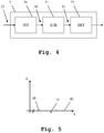
- Fig. 4 is a detail view of the digital processing device 7 from Fig. 3 shown.
- the digital processing device 7 receives the digital measuring signal 53 from the analog-digital converter 6.
- the digital processing device 7 includes a transformation device 70, a subtraction device 71 and a detection device 72.
- the transformation device 70 is connected to the Analog-to-digital converter 6 off Fig. 3 connected.
- the subtraction device 71 is connected to the transformation device 70 and to the detection device 72.
- the detection device 72 is equipped with the control device 9 Fig. 3 connected.
- the digital measurement signal is supplied to the transformation device 70 and transformed by the latter into a measurement signal in the frequency range 54.
- a Fast Fourier Transformation is used.
- the measuring signal in the frequency range 54 corresponds to the in Fig. 2b shown total signal.
- the measuring signal in the frequency range 54 is then supplied to the subtraction device 71, which subtracts a first sideband of the total signal from a second sideband of the total signal.
- Fig. 2b Since the two sidebands of an amplitude-modulated signal are symmetrical with respect to the carrier, this results in a complete extinction of the signal, if only one signal was part of the measurement signal. However, this asymmetry can be found in Fig. 2b can not be easily recognized. In particular shows Fig. 2b an ideal signal without noise. In a real signal, the slight asymmetries of the signal would turn off Fig. 2b disappear in the stronger signal.
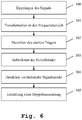
- the subtraction device 71 thus first determines the exact carrier position in the frequency range of the measurement signal in the frequency range 54. Subsequently, a reflection of a sideband is performed at this determined carrier position. The mirrored sideband is subtracted from the non-mirrored sideband. A residual signal 55 resulting in the case of a double transmission is in Fig. 5 shown.
- a residual signal 55 generated in this way is subsequently transmitted to the detection device 72 which, from the signal components present in the residual signal 55, concludes the presence or absence of a double emission.
- a threshold value comparison can be used.
- the residual signal 55 can first be processed, for example by an amount formation or a power generation. The processed residual signal can then be examined by means of a threshold comparison. If the threshold is exceeded, it is concluded that the presence of a double transmission and this the control device 9 Fig. 3 communicated. The absence of a double e-mail is also communicated to the control device 9.
- rotor modulations ie modulations
- Such rotor modulations generate periodic continuations of the transmission signal in the frequency domain.
- the periodicity is specified by the number of sheets of the rotor and the speed.
- the detection device 72 additionally performs a rotor modulation compensation. In this case, the detection device 72 searches specifically for rotor modulations, which are detected on the basis of the known periodicity and removes these periodic repetitions of the signal in the frequency domain before the threshold value comparison is performed.
- the residual signal 55 is off Fig. 4 shown in the case of a double dispatch.
- the residual signal 55 here includes two signal components 40, 41, which correspond to the in Fig. 2b difficult to recognize asymmetries of the overall signal. Now that the symmetrical signal components have been removed, these asymmetric signal components can be easily detected.
- a threshold 42 is shown, by means of which, for example, the presence of the double emission is detected.
- a measurement signal is received.
- This measurement signal includes at least a first signal, but optionally a second signal.
- the measurement signal is transformed into the frequency domain.
- a strongest carrier within the received signal is detected.
- the two sidebands which are defined by the two spectral sides of the detected strongest carrier, are subtracted from one another. At first, one of the sidebands is mirrored at the carrier position.
- a fifth step 104 remaining signal components are detected after the subtraction.
- a double transmission is determined.
Landscapes
- Engineering & Computer Science (AREA)
- Computer Networks & Wireless Communication (AREA)
- Signal Processing (AREA)
- Physics & Mathematics (AREA)
- Electromagnetism (AREA)
- Power Engineering (AREA)
- Radar Systems Or Details Thereof (AREA)
- Monitoring And Testing Of Transmission In General (AREA)
Claims (11)
- Appareil de mesure pour la détection de la présence simultanée d'au moins un premier signal (11) modulé en amplitude et d'un deuxième signal (13) modulé en amplitude dans un signal de mesure (5), comprenant un dispositif de réception (3) pour la réception du signal de mesure (50) sous forme de signal de mesure numérique (53), et un dispositif de traitement de données (7),
le dispositif de traitement de données (7) comportant un dispositif de transformation (70) pour la transformation du signal de mesure numérique (53) en un signal de mesure dans la plage de fréquences (54),
caractérisé
en ce que le dispositif de traitement de données (7) comporte un dispositif de soustraction (71) pour soustraire une première bande latérale (30) du signal de mesure dans la plage de fréquences (54) d'une deuxième bande latérale (31) du signal de mesure dans la plage de fréquences (54), le dispositif de soustraction (71) produisant à cette occasion un signal restant (55), et en ce que le dispositif de soustraction (71) est conçu pour détecter une porteuse (32) la plus intense présente dans le signal de mesure, les bandes latérales (30, 31) du signal de mesure (50) étant séparées par la porteuse (32) la plus intense dans le signal de mesure (50), et/ou en ce que le dispositif de soustraction (71) est conçu pour symétriser par réflexion l'une des bandes latérales (30, 31) du signal de mesure dans la plage de fréquences (54), avant la soustraction, relativement à une position d'une porteuse (32) la plus intense présente dans le signal de mesure (50), et
en ce que le dispositif de traitement de données (7) renferme un dispositif de détection (72) pour la détection de la présence du deuxième signal (13) modulé en amplitude dans le signal de mesure (50) en se basant sur des composantes de signal résiduelles du signal restant (55). - Appareil de mesure selon la revendication 1,
caractérisé
en ce que le dispositif de réception (3) traite le signal de mesure (50) uniquement par des opérations linéaires, avant de numériser le signal de mesure (50) pour l'obtention du signal de mesure numérisé (53). - Appareil de mesure selon la revendication 1 ou la revendication 2,
caractérisé
en ce que le premier signal (11) modulé en amplitude et le deuxième signal (13) modulé en amplitude sont respectivement des signaux modulés en amplitude avec chacun une porteuse (22a, 22b). - Appareil de mesure selon la revendication 1,
caractérisé
en ce que le dispositif de détection (72) est conçu pour déterminer la présence du deuxième signal (13) modulé en amplitude dans le signal de mesure (50), au moyen d'une comparaison à valeur de seuil de composantes de signal résiduelles dans le signal restant (55), ou bien au moyen d'une comparaison à valeur de seuil de puissances additionnées de composantes de signal résiduelles dans le signal restant (55). - Appareil de mesure selon la revendication 1 ou la revendication 4,
caractérisé
en ce que le dispositif de détection (72) est conçu pour détecter des modulations de rotor, qui apparaissent par les pales de rotor en rotation dans un avion entraîné par hélices, du premier signal (11) modulé en amplitude et/ou du deuxième signal (13) modulé en amplitude, et éliminer des modulations de rotor détectées du premier signal (11) modulé en amplitude et/ou du deuxième signal (13) modulé en amplitude, du premier signal (11) modulé en amplitude et/ou du deuxième signal (13) modulé en amplitude,
ou bien faire abstraction des modulations de rotor détectées du premier signal (11) modulé en amplitude et/ou du deuxième signal (13) modulé en amplitude, lors de la détection de la présence du deuxième signal (13) modulé en amplitude dans le signal de mesure (50). - Procédé de mesure pour la détection de la présence simultanée d'au moins un premier signal (11) modulé en amplitude et d'un deuxième signal (13) modulé en amplitude dans un signal de mesure (50), comprenant les étapes suivantes :- réception du signal de mesure (50) sous forme de signal de mesure numérique (53),- transformation du signal de mesure numérique (53) en un signal de mesure dans la plage de fréquences (54),caractérisé
en ce que le procédé comprend en supplément l'étape suivante :- soustraction d'une première bande latérale (30) du signal de mesure dans la plage de fréquences (54) d'une deuxième bande latérale du signal de mesure dans la plage de fréquences (54), en produisant à cette occasion un signal restant (55), eten ce que l'on détecte une porteuse (32) la plus intense présente dans le signal de mesure, les bandes latérales (30, 31) du signal de mesure (50) étant séparées par la porteuse (32) la plus intense dans le signal de mesure (50), et/ou
en ce que l'on symétrise par réflexion l'une des bandes latérales (30, 31) du signal de mesure dans la plage de fréquences (54), avant la soustraction, relativement à une position d'une porteuse (32) la plus intense présente dans le signal de mesure (50), et
en ce que l'on détecte une présence du deuxième signal (13) modulé en amplitude dans le signal de mesure (50) en se basant sur des composantes de signal résiduelles du signal restant (55). - Procédé de mesure selon la revendication 6,
caractérisé
en ce que l'on traite le signal de mesure (50) uniquement par des opérations linéaires, avant de numériser le signal de mesure (50) pour l'obtention du signal de mesure numérisé (53). - Procédé de mesure selon la revendication 6,
caractérisé
en ce que l'on détermine la présence du deuxième signal (13) modulé en amplitude dans le signal de mesure (50) au moyen d'une comparaison à valeur de seuil de composantes de signal résiduelles dans le signal restant (55), ou bien au moyen d'une comparaison à valeur de seuil de puissances additionnées de composantes de signal résiduelles dans le signal restant (55). - Procédé de mesure selon l'une des revendications 6 à 8,
caractérisé
en ce que l'on détecte des modulations de rotor, qui apparaissent par les pales de rotor en rotation dans un avion entraîné par hélices, du premier signal (11) modulé en amplitude et/ou du deuxième signal (13) modulé en amplitude, et
en ce que l'on élimine des modulations de rotor détectées du premier signal (11) modulé en amplitude et/ou du deuxième signal (13) modulé en amplitude, du premier signal (11) modulé en amplitude et/ou du deuxième signal (13) modulé en amplitude,
ou bien en ce que l'on fait abstraction des modulations de rotor détectées du premier signal (11) modulé en amplitude et/ou du deuxième signal (13) modulé en amplitude, lors de la détection de la présence du deuxième signal (13) modulé en amplitude dans le signal de mesure (50). - Programme d'ordinateur comprenant des moyens de codes de programme pour exécuter toutes les étapes d'un procédé selon l'une des revendications 6 à 9 lorsque le programme est exécuté sur un ordinateur ou un processeur de traitement de signal numérique.
- Produit de programme d'ordinateur comprenant un support lisible par ordinateur, sur lequel sont mémorisés des moyens de codes de programmes en vue d'exécuter toutes les étapes d'un procédé selon l'une des revendications 6 à 9 lorsque le programme est exécuté sur un ordinateur ou un processeur de traitement de signal numérique.
Priority Applications (1)
| Application Number | Priority Date | Filing Date | Title |
|---|---|---|---|
| EP16201301.5A EP3154233B2 (fr) | 2013-06-25 | 2014-05-09 | Appareil de mesure et procédé de mesure destinés à la détection de doubles émissions simultanées |
Applications Claiming Priority (2)
| Application Number | Priority Date | Filing Date | Title |
|---|---|---|---|
| DE201310212067 DE102013212067A1 (de) | 2013-06-25 | 2013-06-25 | Messgerät und Messverfahren zur Detektion von simultanen Doppelaussendungen |
| PCT/EP2014/059559 WO2014206623A1 (fr) | 2013-06-25 | 2014-05-09 | Détection de deux émissions simultanées |
Related Child Applications (2)
| Application Number | Title | Priority Date | Filing Date |
|---|---|---|---|
| EP16201301.5A Division EP3154233B2 (fr) | 2013-06-25 | 2014-05-09 | Appareil de mesure et procédé de mesure destinés à la détection de doubles émissions simultanées |
| EP16201301.5A Division-Into EP3154233B2 (fr) | 2013-06-25 | 2014-05-09 | Appareil de mesure et procédé de mesure destinés à la détection de doubles émissions simultanées |
Publications (3)
| Publication Number | Publication Date |
|---|---|
| EP3014831A1 EP3014831A1 (fr) | 2016-05-04 |
| EP3014831B1 true EP3014831B1 (fr) | 2017-03-15 |
| EP3014831B2 EP3014831B2 (fr) | 2021-01-27 |
Family
ID=50732153
Family Applications (2)
| Application Number | Title | Priority Date | Filing Date |
|---|---|---|---|
| EP14724398.4A Active EP3014831B2 (fr) | 2013-06-25 | 2014-05-09 | Détection de transmission double |
| EP16201301.5A Active EP3154233B2 (fr) | 2013-06-25 | 2014-05-09 | Appareil de mesure et procédé de mesure destinés à la détection de doubles émissions simultanées |
Family Applications After (1)
| Application Number | Title | Priority Date | Filing Date |
|---|---|---|---|
| EP16201301.5A Active EP3154233B2 (fr) | 2013-06-25 | 2014-05-09 | Appareil de mesure et procédé de mesure destinés à la détection de doubles émissions simultanées |
Country Status (6)
| Country | Link |
|---|---|
| US (2) | US9641365B2 (fr) |
| EP (2) | EP3014831B2 (fr) |
| CN (1) | CN105324970B (fr) |
| DE (1) | DE102013212067A1 (fr) |
| RU (1) | RU2656705C2 (fr) |
| WO (1) | WO2014206623A1 (fr) |
Families Citing this family (8)
| Publication number | Priority date | Publication date | Assignee | Title |
|---|---|---|---|---|
| DE102013212067A1 (de) | 2013-06-25 | 2015-01-08 | Rohde & Schwarz Gmbh & Co. Kg | Messgerät und Messverfahren zur Detektion von simultanen Doppelaussendungen |
| US9825794B2 (en) * | 2013-06-25 | 2017-11-21 | Thuy Duong NGUYEN | Weak signal detection in double transmission |
| GB2522083B (en) | 2014-03-24 | 2016-02-10 | Park Air Systems Ltd | Simultaneous call transmission detection |
| DE102016205609A1 (de) * | 2016-04-05 | 2017-10-05 | Rohde & Schwarz Gmbh & Co. Kg | Verarbeitungsvorrichtung und Verfahren |
| WO2018092581A1 (fr) * | 2016-11-16 | 2018-05-24 | 株式会社日立国際電気 | Dispositif radio |
| EP3438978B1 (fr) * | 2017-08-02 | 2023-12-27 | Rohde & Schwarz GmbH & Co. KG | Système d'évaluation de signal et procédé d'évaluation de signal |
| WO2019180771A1 (fr) * | 2018-03-19 | 2019-09-26 | 株式会社日立国際電気 | Dispositif de station de commande |
| EP3678301B1 (fr) | 2019-01-07 | 2024-12-04 | Rohde & Schwarz GmbH & Co. KG | Système de contrôle du trafic aérien ainsi qu'un procédé de gestion de transmission d'appels simultanés |
Citations (4)
| Publication number | Priority date | Publication date | Assignee | Title |
|---|---|---|---|---|
| EP0410663A2 (fr) | 1989-07-28 | 1991-01-30 | Bose Corporation | Réduction de bruit en modulation d'amplitude |
| US20040165680A1 (en) | 2003-02-24 | 2004-08-26 | Kroeger Brian William | Coherent AM demodulator using a weighted LSB/USB sum for interference mitigation |
| DE102007037105A1 (de) | 2007-05-09 | 2008-11-13 | Rohde & Schwarz Gmbh & Co. Kg | Verfahren und Vorrichtung zur Detektion von simultaner Doppelaussendung von AM-Signalen |
| DE102011080999A1 (de) | 2011-08-16 | 2013-02-21 | Rohde & Schwarz Gmbh & Co. Kg | Verfahren und Vorrichtung zur Detektion von zeitgleich im selben Kanal übertragenen Flugfunksignalen |
Family Cites Families (15)
| Publication number | Priority date | Publication date | Assignee | Title |
|---|---|---|---|---|
| US5063574A (en) * | 1990-03-06 | 1991-11-05 | Moose Paul H | Multi-frequency differentially encoded digital communication for high data rate transmission through unequalized channels |
| US5323337A (en) * | 1992-08-04 | 1994-06-21 | Loral Aerospace Corp. | Signal detector employing mean energy and variance of energy content comparison for noise detection |
| WO1998002760A1 (fr) * | 1996-06-28 | 1998-01-22 | Milkovich Systems Engineering | Processeur ameliore de detection de transformees de fourier rapides mettant en oeuvre des principes evolues dans le domaine des frequences |
| US6182033B1 (en) * | 1998-01-09 | 2001-01-30 | At&T Corp. | Modular approach to speech enhancement with an application to speech coding |
| US6573948B1 (en) * | 1999-06-25 | 2003-06-03 | Samsung Electronics Co., Ltd. | Equalizing intermediate-frequency signals before demodulating them in a digital television receiver |
| US6405147B1 (en) * | 1999-09-10 | 2002-06-11 | Condor Systems, Inc. | Signal transfer device measurement system and method |
| GB2359432B (en) * | 2000-02-17 | 2002-07-03 | Wireless Systems Int Ltd | Signal detection |
| EP1160969B1 (fr) * | 2000-05-29 | 2006-08-16 | Sony Deutschland GmbH | Détection de distorsion de signaux AM |
| EP1160978A1 (fr) * | 2000-05-29 | 2001-12-05 | Sony International (Europe) GmbH | Filtre numérique |
| US6961372B2 (en) * | 2001-08-13 | 2005-11-01 | Broadcom Corporation | Non-iterative time-domain equalizer |
| RU2317644C2 (ru) * | 2003-01-10 | 2008-02-20 | Сони Дойчланд Гмбх | Одновременная передача мцв/ам сигнала |
| US7619964B2 (en) * | 2004-07-08 | 2009-11-17 | Nokia Corporation | High doppler channel estimation for OFD multiple antenna systems |
| US8081753B2 (en) * | 2007-04-02 | 2011-12-20 | Microsoft Corporation | Hybrid echo canceller controllers |
| FR2920063B1 (fr) * | 2007-08-17 | 2011-04-29 | Thales Sa | Recepteur de signaux haute frequence recevant simultanement plusieurs tels signaux |
| DE102013212067A1 (de) | 2013-06-25 | 2015-01-08 | Rohde & Schwarz Gmbh & Co. Kg | Messgerät und Messverfahren zur Detektion von simultanen Doppelaussendungen |
-
2013
- 2013-06-25 DE DE201310212067 patent/DE102013212067A1/de not_active Withdrawn
-
2014
- 2014-05-09 RU RU2015151715A patent/RU2656705C2/ru active
- 2014-05-09 EP EP14724398.4A patent/EP3014831B2/fr active Active
- 2014-05-09 WO PCT/EP2014/059559 patent/WO2014206623A1/fr not_active Ceased
- 2014-05-09 EP EP16201301.5A patent/EP3154233B2/fr active Active
- 2014-05-09 CN CN201480036282.9A patent/CN105324970B/zh active Active
- 2014-05-09 US US14/900,019 patent/US9641365B2/en active Active
-
2017
- 2017-02-24 US US15/442,264 patent/US10027517B2/en active Active
Patent Citations (4)
| Publication number | Priority date | Publication date | Assignee | Title |
|---|---|---|---|---|
| EP0410663A2 (fr) | 1989-07-28 | 1991-01-30 | Bose Corporation | Réduction de bruit en modulation d'amplitude |
| US20040165680A1 (en) | 2003-02-24 | 2004-08-26 | Kroeger Brian William | Coherent AM demodulator using a weighted LSB/USB sum for interference mitigation |
| DE102007037105A1 (de) | 2007-05-09 | 2008-11-13 | Rohde & Schwarz Gmbh & Co. Kg | Verfahren und Vorrichtung zur Detektion von simultaner Doppelaussendung von AM-Signalen |
| DE102011080999A1 (de) | 2011-08-16 | 2013-02-21 | Rohde & Schwarz Gmbh & Co. Kg | Verfahren und Vorrichtung zur Detektion von zeitgleich im selben Kanal übertragenen Flugfunksignalen |
Non-Patent Citations (5)
| Title |
|---|
| "The IBOC HANDBOOK", 2007, article MAXSON, D.P.: "Chapter 8 From the Top Down: The Physical Layer- AM OFDM", pages: 221 - 232, XP055602375 |
| "Voice over internet protocol (VoIP) Air Traffic Management (ATM) system operational and technical requirements", THE EUROPEAN ORGANISATION FOR CIVIL AVIATION EQUIPMENT, February 2009 (2009-02-01), XP055602435 |
| AZZOUZ, E.E. ET AL.: "Procedure for automatic recognition of analogue and digital modulations", IEE PROCEEDINGS - COMMUNICATIONS, vol. 143, 5 October 1996 (1996-10-05), pages 259 - 266, XP006006273, DOI: 10.1049/ip-com:19960752 |
| KADAR, I.: "An analysis of helicopter rotor modulation interface", IEEE TRANSACTION ON AEROSPACE AND ELECTRONIC SYSTEMS, vol. AES-9, no. 3, 3 May 1973 (1973-05-03), pages 434 - 441, XP011167314 |
| OETTING, J.D.: "A comparison of modulation techniques for digital radio", IEEE TRANSACTIONS ON COMMUNICATIONS, vol. 27, 12 December 1979 (1979-12-12), pages 1752 - 1762, XP000758733, DOI: 10.1109/TCOM.1979.1094370 |
Also Published As
| Publication number | Publication date |
|---|---|
| CN105324970A (zh) | 2016-02-10 |
| US9641365B2 (en) | 2017-05-02 |
| EP3154233B1 (fr) | 2017-09-13 |
| EP3154233B2 (fr) | 2021-03-17 |
| WO2014206623A1 (fr) | 2014-12-31 |
| EP3154233A1 (fr) | 2017-04-12 |
| RU2015151715A (ru) | 2017-07-28 |
| RU2656705C2 (ru) | 2018-06-06 |
| US20170163455A1 (en) | 2017-06-08 |
| US10027517B2 (en) | 2018-07-17 |
| EP3014831B2 (fr) | 2021-01-27 |
| HK1215500A1 (zh) | 2016-08-26 |
| DE102013212067A1 (de) | 2015-01-08 |
| CN105324970B (zh) | 2019-02-19 |
| EP3014831A1 (fr) | 2016-05-04 |
| US20160149737A1 (en) | 2016-05-26 |
Similar Documents
| Publication | Publication Date | Title |
|---|---|---|
| EP3014831B2 (fr) | Détection de transmission double | |
| DE102014226073A1 (de) | Verfahren und Vorrichtung zum Betreiben eines Radarsystems eines Kraftfahrzeugs | |
| EP2174413B1 (fr) | Procédé et dispositif de détection de double transmission simultanée de signaux am | |
| EP3143415B1 (fr) | Procédé et appareil de mesure d'intermodulation | |
| DE102008050117A1 (de) | Kalibration einer Radareinheit mit gerätespezifischen Korrekturkurven | |
| EP3195488B1 (fr) | Procédé de mesure d'intermodulation passive et dispositif de mesure | |
| EP3906421B1 (fr) | Procédé pour faire fonctionner un dispositif de contrôle pour tester un capteur de distance fonctionnant avec des ondes électromagnétiques et dispositif de contrôle correspondant | |
| DE102017007961A1 (de) | Verfahren und Vorrichtung zum Erkennen eines Störzustands eines Radarsensors | |
| DE102014114107A1 (de) | Radarsensor | |
| EP3655786B1 (fr) | Procédé et système d'identification de décharges partielles dans une ressource électrique | |
| DE102015113204A1 (de) | Empfangssignalverarbeitungsvorrichtung, Radar und Objektdetektierverfahren | |
| DE102006038857A1 (de) | Funksender | |
| WO2016050628A1 (fr) | Capteur radar | |
| DE102018200753A1 (de) | Verfahren und Vorrichtung zum Korrigieren eines Radarsignals und Radarvorrichtung | |
| EP3132282A1 (fr) | Dispositif et procédé de détection sonore d'un environnement | |
| EP2721422B1 (fr) | Procédé et appareil de mesure pour la suppression de signaux parasites | |
| EP4435478A1 (fr) | Capteur optique et procédé de fonctionnement d'un capteur optique | |
| DE112018004882T5 (de) | Herzschlagmessvorrichtung | |
| DE102014009710B4 (de) | Verfahren zur Fehlererkennung in einem Messsystem | |
| DE102012212902A1 (de) | Verfahren zum Betrieb eines Umfelderfassungssystems eines Fahrzeugs und Umfelderfassungssystem | |
| EP2622418A1 (fr) | Agencement de circuits et procédé de surveillance d'un processeur dsp dans le cadre d'une application critique pour la sécurité | |
| DE102011075256B4 (de) | Messgerät und Messverfahren zur Vermessung von Antennen | |
| DE102010034492A1 (de) | Verfahren zur Auswertung von Signalen einer Sensoreinheit und Vorrichtung zur Umfelderfassung in einem Fahrzeug | |
| DE102020203238A1 (de) | Verfahren und System zur Bestimmung eines Mehrwegeeinflusses, Verfahren zur Positionsbestimmung eines Objekts und Vorrichtung zur Datenverarbeitung | |
| DE102018200763A1 (de) | Vorrichtung und Verfahren zum Verarbeiten eines Eingabesignals und Radarvorrichtung |
Legal Events
| Date | Code | Title | Description |
|---|---|---|---|
| PUAI | Public reference made under article 153(3) epc to a published international application that has entered the european phase |
Free format text: ORIGINAL CODE: 0009012 |
|
| 17P | Request for examination filed |
Effective date: 20151126 |
|
| AK | Designated contracting states |
Kind code of ref document: A1 Designated state(s): AL AT BE BG CH CY CZ DE DK EE ES FI FR GB GR HR HU IE IS IT LI LT LU LV MC MK MT NL NO PL PT RO RS SE SI SK SM TR |
|
| AX | Request for extension of the european patent |
Extension state: BA ME |
|
| DAX | Request for extension of the european patent (deleted) | ||
| GRAP | Despatch of communication of intention to grant a patent |
Free format text: ORIGINAL CODE: EPIDOSNIGR1 |
|
| INTG | Intention to grant announced |
Effective date: 20161027 |
|
| STAA | Information on the status of an ep patent application or granted ep patent |
Free format text: STATUS: GRANT OF PATENT IS INTENDED |
|
| GRAS | Grant fee paid |
Free format text: ORIGINAL CODE: EPIDOSNIGR3 |
|
| GRAA | (expected) grant |
Free format text: ORIGINAL CODE: 0009210 |
|
| STAA | Information on the status of an ep patent application or granted ep patent |
Free format text: STATUS: THE PATENT HAS BEEN GRANTED |
|
| AK | Designated contracting states |
Kind code of ref document: B1 Designated state(s): AL AT BE BG CH CY CZ DE DK EE ES FI FR GB GR HR HU IE IS IT LI LT LU LV MC MK MT NL NO PL PT RO RS SE SI SK SM TR |
|
| REG | Reference to a national code |
Ref country code: CH Ref legal event code: EP Ref country code: GB Ref legal event code: FG4D Free format text: NOT ENGLISH |
|
| REG | Reference to a national code |
Ref country code: IE Ref legal event code: FG4D Free format text: LANGUAGE OF EP DOCUMENT: GERMAN |
|
| REG | Reference to a national code |
Ref country code: FR Ref legal event code: PLFP Year of fee payment: 4 |
|
| REG | Reference to a national code |
Ref country code: AT Ref legal event code: REF Ref document number: 876591 Country of ref document: AT Kind code of ref document: T Effective date: 20170415 |
|
| REG | Reference to a national code |
Ref country code: DE Ref legal event code: R096 Ref document number: 502014003050 Country of ref document: DE |
|
| REG | Reference to a national code |
Ref country code: NL Ref legal event code: MP Effective date: 20170315 |
|
| REG | Reference to a national code |
Ref country code: LT Ref legal event code: MG4D |
|
| PG25 | Lapsed in a contracting state [announced via postgrant information from national office to epo] |
Ref country code: NO Free format text: LAPSE BECAUSE OF FAILURE TO SUBMIT A TRANSLATION OF THE DESCRIPTION OR TO PAY THE FEE WITHIN THE PRESCRIBED TIME-LIMIT Effective date: 20170615 Ref country code: GR Free format text: LAPSE BECAUSE OF FAILURE TO SUBMIT A TRANSLATION OF THE DESCRIPTION OR TO PAY THE FEE WITHIN THE PRESCRIBED TIME-LIMIT Effective date: 20170616 Ref country code: HR Free format text: LAPSE BECAUSE OF FAILURE TO SUBMIT A TRANSLATION OF THE DESCRIPTION OR TO PAY THE FEE WITHIN THE PRESCRIBED TIME-LIMIT Effective date: 20170315 Ref country code: FI Free format text: LAPSE BECAUSE OF FAILURE TO SUBMIT A TRANSLATION OF THE DESCRIPTION OR TO PAY THE FEE WITHIN THE PRESCRIBED TIME-LIMIT Effective date: 20170315 Ref country code: LT Free format text: LAPSE BECAUSE OF FAILURE TO SUBMIT A TRANSLATION OF THE DESCRIPTION OR TO PAY THE FEE WITHIN THE PRESCRIBED TIME-LIMIT Effective date: 20170315 |
|
| PG25 | Lapsed in a contracting state [announced via postgrant information from national office to epo] |
Ref country code: BG Free format text: LAPSE BECAUSE OF FAILURE TO SUBMIT A TRANSLATION OF THE DESCRIPTION OR TO PAY THE FEE WITHIN THE PRESCRIBED TIME-LIMIT Effective date: 20170615 Ref country code: LU Free format text: LAPSE BECAUSE OF NON-PAYMENT OF DUE FEES Effective date: 20170531 Ref country code: LV Free format text: LAPSE BECAUSE OF FAILURE TO SUBMIT A TRANSLATION OF THE DESCRIPTION OR TO PAY THE FEE WITHIN THE PRESCRIBED TIME-LIMIT Effective date: 20170315 Ref country code: SE Free format text: LAPSE BECAUSE OF FAILURE TO SUBMIT A TRANSLATION OF THE DESCRIPTION OR TO PAY THE FEE WITHIN THE PRESCRIBED TIME-LIMIT Effective date: 20170315 Ref country code: RS Free format text: LAPSE BECAUSE OF FAILURE TO SUBMIT A TRANSLATION OF THE DESCRIPTION OR TO PAY THE FEE WITHIN THE PRESCRIBED TIME-LIMIT Effective date: 20170315 |
|
| PG25 | Lapsed in a contracting state [announced via postgrant information from national office to epo] |
Ref country code: NL Free format text: LAPSE BECAUSE OF FAILURE TO SUBMIT A TRANSLATION OF THE DESCRIPTION OR TO PAY THE FEE WITHIN THE PRESCRIBED TIME-LIMIT Effective date: 20170315 |
|
| PG25 | Lapsed in a contracting state [announced via postgrant information from national office to epo] |
Ref country code: CZ Free format text: LAPSE BECAUSE OF FAILURE TO SUBMIT A TRANSLATION OF THE DESCRIPTION OR TO PAY THE FEE WITHIN THE PRESCRIBED TIME-LIMIT Effective date: 20170315 Ref country code: EE Free format text: LAPSE BECAUSE OF FAILURE TO SUBMIT A TRANSLATION OF THE DESCRIPTION OR TO PAY THE FEE WITHIN THE PRESCRIBED TIME-LIMIT Effective date: 20170315 Ref country code: IT Free format text: LAPSE BECAUSE OF FAILURE TO SUBMIT A TRANSLATION OF THE DESCRIPTION OR TO PAY THE FEE WITHIN THE PRESCRIBED TIME-LIMIT Effective date: 20170315 Ref country code: SK Free format text: LAPSE BECAUSE OF FAILURE TO SUBMIT A TRANSLATION OF THE DESCRIPTION OR TO PAY THE FEE WITHIN THE PRESCRIBED TIME-LIMIT Effective date: 20170315 Ref country code: RO Free format text: LAPSE BECAUSE OF FAILURE TO SUBMIT A TRANSLATION OF THE DESCRIPTION OR TO PAY THE FEE WITHIN THE PRESCRIBED TIME-LIMIT Effective date: 20170315 Ref country code: ES Free format text: LAPSE BECAUSE OF FAILURE TO SUBMIT A TRANSLATION OF THE DESCRIPTION OR TO PAY THE FEE WITHIN THE PRESCRIBED TIME-LIMIT Effective date: 20170315 |
|
| PG25 | Lapsed in a contracting state [announced via postgrant information from national office to epo] |
Ref country code: PT Free format text: LAPSE BECAUSE OF FAILURE TO SUBMIT A TRANSLATION OF THE DESCRIPTION OR TO PAY THE FEE WITHIN THE PRESCRIBED TIME-LIMIT Effective date: 20170717 Ref country code: SM Free format text: LAPSE BECAUSE OF FAILURE TO SUBMIT A TRANSLATION OF THE DESCRIPTION OR TO PAY THE FEE WITHIN THE PRESCRIBED TIME-LIMIT Effective date: 20170315 Ref country code: IS Free format text: LAPSE BECAUSE OF FAILURE TO SUBMIT A TRANSLATION OF THE DESCRIPTION OR TO PAY THE FEE WITHIN THE PRESCRIBED TIME-LIMIT Effective date: 20170715 Ref country code: PL Free format text: LAPSE BECAUSE OF FAILURE TO SUBMIT A TRANSLATION OF THE DESCRIPTION OR TO PAY THE FEE WITHIN THE PRESCRIBED TIME-LIMIT Effective date: 20170315 |
|
| REG | Reference to a national code |
Ref country code: DE Ref legal event code: R026 Ref document number: 502014003050 Country of ref document: DE |
|
| REG | Reference to a national code |
Ref country code: CH Ref legal event code: PL |
|
| PLBI | Opposition filed |
Free format text: ORIGINAL CODE: 0009260 |
|
| PLAX | Notice of opposition and request to file observation + time limit sent |
Free format text: ORIGINAL CODE: EPIDOSNOBS2 |
|
| PLAS | Information related to reply of patent proprietor to notice(s) of opposition deleted |
Free format text: ORIGINAL CODE: EPIDOSDOBS3 |
|
| PLBB | Reply of patent proprietor to notice(s) of opposition received |
Free format text: ORIGINAL CODE: EPIDOSNOBS3 |
|
| PG25 | Lapsed in a contracting state [announced via postgrant information from national office to epo] |
Ref country code: DK Free format text: LAPSE BECAUSE OF FAILURE TO SUBMIT A TRANSLATION OF THE DESCRIPTION OR TO PAY THE FEE WITHIN THE PRESCRIBED TIME-LIMIT Effective date: 20170315 Ref country code: MC Free format text: LAPSE BECAUSE OF FAILURE TO SUBMIT A TRANSLATION OF THE DESCRIPTION OR TO PAY THE FEE WITHIN THE PRESCRIBED TIME-LIMIT Effective date: 20170315 |
|
| 26 | Opposition filed |
Opponent name: PARK AIR SYSTEMS LIMITED Effective date: 20171215 |
|
| REG | Reference to a national code |
Ref country code: IE Ref legal event code: MM4A |
|
| PG25 | Lapsed in a contracting state [announced via postgrant information from national office to epo] |
Ref country code: LI Free format text: LAPSE BECAUSE OF NON-PAYMENT OF DUE FEES Effective date: 20170531 Ref country code: SI Free format text: LAPSE BECAUSE OF FAILURE TO SUBMIT A TRANSLATION OF THE DESCRIPTION OR TO PAY THE FEE WITHIN THE PRESCRIBED TIME-LIMIT Effective date: 20170315 Ref country code: CH Free format text: LAPSE BECAUSE OF NON-PAYMENT OF DUE FEES Effective date: 20170531 |
|
| PG25 | Lapsed in a contracting state [announced via postgrant information from national office to epo] |
Ref country code: LU Free format text: LAPSE BECAUSE OF NON-PAYMENT OF DUE FEES Effective date: 20170509 |
|
| REG | Reference to a national code |
Ref country code: BE Ref legal event code: MM Effective date: 20170531 |
|
| PG25 | Lapsed in a contracting state [announced via postgrant information from national office to epo] |
Ref country code: IE Free format text: LAPSE BECAUSE OF NON-PAYMENT OF DUE FEES Effective date: 20170509 |
|
| PLBB | Reply of patent proprietor to notice(s) of opposition received |
Free format text: ORIGINAL CODE: EPIDOSNOBS3 |
|
| REG | Reference to a national code |
Ref country code: FR Ref legal event code: PLFP Year of fee payment: 5 |
|
| PG25 | Lapsed in a contracting state [announced via postgrant information from national office to epo] |
Ref country code: BE Free format text: LAPSE BECAUSE OF NON-PAYMENT OF DUE FEES Effective date: 20170531 |
|
| PG25 | Lapsed in a contracting state [announced via postgrant information from national office to epo] |
Ref country code: MT Free format text: LAPSE BECAUSE OF FAILURE TO SUBMIT A TRANSLATION OF THE DESCRIPTION OR TO PAY THE FEE WITHIN THE PRESCRIBED TIME-LIMIT Effective date: 20170315 |
|
| APBM | Appeal reference recorded |
Free format text: ORIGINAL CODE: EPIDOSNREFNO |
|
| APBP | Date of receipt of notice of appeal recorded |
Free format text: ORIGINAL CODE: EPIDOSNNOA2O |
|
| APAH | Appeal reference modified |
Free format text: ORIGINAL CODE: EPIDOSCREFNO |
|
| PG25 | Lapsed in a contracting state [announced via postgrant information from national office to epo] |
Ref country code: HU Free format text: LAPSE BECAUSE OF FAILURE TO SUBMIT A TRANSLATION OF THE DESCRIPTION OR TO PAY THE FEE WITHIN THE PRESCRIBED TIME-LIMIT; INVALID AB INITIO Effective date: 20140509 |
|
| APBQ | Date of receipt of statement of grounds of appeal recorded |
Free format text: ORIGINAL CODE: EPIDOSNNOA3O |
|
| PG25 | Lapsed in a contracting state [announced via postgrant information from national office to epo] |
Ref country code: CY Free format text: LAPSE BECAUSE OF FAILURE TO SUBMIT A TRANSLATION OF THE DESCRIPTION OR TO PAY THE FEE WITHIN THE PRESCRIBED TIME-LIMIT Effective date: 20170315 |
|
| PG25 | Lapsed in a contracting state [announced via postgrant information from national office to epo] |
Ref country code: MK Free format text: LAPSE BECAUSE OF FAILURE TO SUBMIT A TRANSLATION OF THE DESCRIPTION OR TO PAY THE FEE WITHIN THE PRESCRIBED TIME-LIMIT Effective date: 20170315 |
|
| PG25 | Lapsed in a contracting state [announced via postgrant information from national office to epo] |
Ref country code: TR Free format text: LAPSE BECAUSE OF FAILURE TO SUBMIT A TRANSLATION OF THE DESCRIPTION OR TO PAY THE FEE WITHIN THE PRESCRIBED TIME-LIMIT Effective date: 20170315 |
|
| PG25 | Lapsed in a contracting state [announced via postgrant information from national office to epo] |
Ref country code: AL Free format text: LAPSE BECAUSE OF FAILURE TO SUBMIT A TRANSLATION OF THE DESCRIPTION OR TO PAY THE FEE WITHIN THE PRESCRIBED TIME-LIMIT Effective date: 20170315 |
|
| REG | Reference to a national code |
Ref country code: AT Ref legal event code: MM01 Ref document number: 876591 Country of ref document: AT Kind code of ref document: T Effective date: 20190509 |
|
| APBU | Appeal procedure closed |
Free format text: ORIGINAL CODE: EPIDOSNNOA9O |
|
| PLBP | Opposition withdrawn |
Free format text: ORIGINAL CODE: 0009264 |
|
| PG25 | Lapsed in a contracting state [announced via postgrant information from national office to epo] |
Ref country code: AT Free format text: LAPSE BECAUSE OF NON-PAYMENT OF DUE FEES Effective date: 20190509 |
|
| PUAH | Patent maintained in amended form |
Free format text: ORIGINAL CODE: 0009272 |
|
| STAA | Information on the status of an ep patent application or granted ep patent |
Free format text: STATUS: PATENT MAINTAINED AS AMENDED |
|
| 27A | Patent maintained in amended form |
Effective date: 20210127 |
|
| AK | Designated contracting states |
Kind code of ref document: B2 Designated state(s): AL AT BE BG CH CY CZ DE DK EE ES FI FR GB GR HR HU IE IS IT LI LT LU LV MC MK MT NL NO PL PT RO RS SE SI SK SM TR |
|
| REG | Reference to a national code |
Ref country code: DE Ref legal event code: R102 Ref document number: 502014003050 Country of ref document: DE |
|
| P01 | Opt-out of the competence of the unified patent court (upc) registered |
Effective date: 20230525 |
|
| PGFP | Annual fee paid to national office [announced via postgrant information from national office to epo] |
Ref country code: DE Payment date: 20250519 Year of fee payment: 12 |
|
| PGFP | Annual fee paid to national office [announced via postgrant information from national office to epo] |
Ref country code: FR Payment date: 20250523 Year of fee payment: 12 |
|
| PGFP | Annual fee paid to national office [announced via postgrant information from national office to epo] |
Ref country code: GB Payment date: 20260324 Year of fee payment: 13 |