EP4435478A1 - Capteur optique et procédé de fonctionnement d'un capteur optique - Google Patents
Capteur optique et procédé de fonctionnement d'un capteur optique Download PDFInfo
- Publication number
- EP4435478A1 EP4435478A1 EP23163987.3A EP23163987A EP4435478A1 EP 4435478 A1 EP4435478 A1 EP 4435478A1 EP 23163987 A EP23163987 A EP 23163987A EP 4435478 A1 EP4435478 A1 EP 4435478A1
- Authority
- EP
- European Patent Office
- Prior art keywords
- optical sensor
- transmitter
- signal
- receiver
- frequency
- Prior art date
- Legal status (The legal status is an assumption and is not a legal conclusion. Google has not performed a legal analysis and makes no representation as to the accuracy of the status listed.)
- Pending
Links
Images




Classifications
-
- G—PHYSICS
- G01—MEASURING; TESTING
- G01V—GEOPHYSICS; GRAVITATIONAL MEASUREMENTS; DETECTING MASSES OR OBJECTS; TAGS
- G01V8/00—Prospecting or detecting by optical means
- G01V8/10—Detecting, e.g. by using light barriers
- G01V8/12—Detecting, e.g. by using light barriers using one transmitter and one receiver
-
- G—PHYSICS
- G01—MEASURING; TESTING
- G01V—GEOPHYSICS; GRAVITATIONAL MEASUREMENTS; DETECTING MASSES OR OBJECTS; TAGS
- G01V8/00—Prospecting or detecting by optical means
- G01V8/10—Detecting, e.g. by using light barriers
- G01V8/12—Detecting, e.g. by using light barriers using one transmitter and one receiver
- G01V8/14—Detecting, e.g. by using light barriers using one transmitter and one receiver using reflectors
-
- G—PHYSICS
- G01—MEASURING; TESTING
- G01V—GEOPHYSICS; GRAVITATIONAL MEASUREMENTS; DETECTING MASSES OR OBJECTS; TAGS
- G01V8/00—Prospecting or detecting by optical means
- G01V8/10—Detecting, e.g. by using light barriers
- G01V8/20—Detecting, e.g. by using light barriers using multiple transmitters or receivers
-
- G—PHYSICS
- G01—MEASURING; TESTING
- G01V—GEOPHYSICS; GRAVITATIONAL MEASUREMENTS; DETECTING MASSES OR OBJECTS; TAGS
- G01V8/00—Prospecting or detecting by optical means
- G01V8/10—Detecting, e.g. by using light barriers
- G01V8/20—Detecting, e.g. by using light barriers using multiple transmitters or receivers
- G01V8/22—Detecting, e.g. by using light barriers using multiple transmitters or receivers using reflectors
Definitions
- the invention relates to an optical sensor and a method for operating an optical sensor.
- the optical sensor is used in particular to detect objects in a monitoring area.
- the optical sensor comprises at least one transmitter that emits light rays and one receiver that receives light rays.
- the optical sensor also comprises an evaluation unit in which an object detection signal is generated depending on the received signals from the receiver.
- the optical sensor works according to the light barrier principle, so that object detection occurs by registering an interruption in the beam path of the light rays passing through the monitoring area.
- the optical sensor has only one transmitter or receiver, it is designed as a light barrier or reflective light barrier. If the optical sensor has several pairs of transmitters and receivers, it is designed as a light curtain or reflective light curtain.
- a general problem with such optical sensors is that external light influences, particularly stray light radiated into the optical sensor by stray light sources, can lead to malfunctions in the optical sensor. Stray light irradiation can, for example, simulate a clear monitoring area even though an object is in the monitoring area.
- the transmitter of the optical sensor emits light beams in the form of coded light pulses. It is also known that the light beams can be modulated with a modulation frequency.
- the invention is based on the object of providing an optical sensor with further improved resistance to interference light and/or sensitivity.
- the invention relates to an optical sensor with at least one transmitter emitting light beams, at least one receiver receiving light beams and an evaluation unit in which an object detection signal is generated depending on the received signals from the receiver.
- the light beams are modulated with a sequence of signal sections.
- the modulated signal sections have a predetermined spectrum in the frequency domain.
- On the receiving side a spectral decomposition of received signals is carried out.
- In the evaluation unit it is checked whether or not a predetermined number of predetermined frequency components and advantageously predetermined amplitudes/phases are present in a spectrally decomposed received signal. Depending on this, it is assessed whether or not the light beams emitted by the transmitter are guided to the receiver.
- the invention also relates to a corresponding method.
- the or each transmitter emits, preferably at regular intervals, light beams in the form of defined signal sections.
- the basic idea of the invention is to carry out a spectral decomposition of received signals registered at the receiver(s) in the evaluation unit.
- a frequency analysis is carried out in the evaluation unit in such a way that it is checked whether frequency components stored in the evaluation unit, in particular as target values, are present in the spectrally decomposed received signal. This provides a safe and reliable statement as to whether the light beams of a transmitter are guided over a measuring path to the assigned receiver or not, which is used to generate the object detection signal.
- a key requirement is that not all of the frequency spectrum of the spectrally decomposed received signal must be detected in order to identify signal sections of the light beams. Instead, a limited number of frequency components to be detected are defined in the evaluation unit as a target value, with the number being selected so that on the one hand the signal sections in the light beams can be reliably identified and on the other hand a high error tolerance and thus availability is given for object detection.
- the spectrum can, for example, consist mainly of frequency lines. These frequency lines deviate from the idealized form for technical reasons (broadening). The presence of such frequency lines can be determined by evaluating the neighboring frequency ranges.
- the accuracy in the detection of signal sections can be increased in particular by weighting the frequency lines present in spectrally decomposed received signals in the evaluation unit with regard to number and/or level and/or phase.
- a signal section has at least approximately the signal curve of a cardinal sine.
- the frequency spectrum of such a cardinal sine is ideally rectangular and can be easily evaluated on the receiving side.
- the or each transmitter emits a sequence of periodically repeating signal sections, whereby a frequency spectrum with spectral lines with at least approximately constant frequency spacing and constant levels is obtained.
- the spectral decomposition of received signals is carried out by means of a spectral analysis. It can also be advantageous if the spectral decomposition is carried out by means of a complex-valued FFT (Fast Fourier Transformation).
- FFT Fast Fourier Transformation
- the level can be determined from the complex spectrum by forming the magnitude and the phase by determining the angle of the complex result. This makes it possible to evaluate the real/imaginary components of the complex spectrum or the magnitude and/or phase of the spectrum.
- sampling frequency lines of the spectral received signal with a sampling frequency that is significantly higher than the frequencies of the spectrally decomposed received signal.
- the sampling frequency is around multiple of the relevant frequency components of the received signal. Good results can be achieved with a factor greater than 2, eg 3. Higher sampling frequencies increase the quality of the results, but also the computational effort.
- the spectrally decomposed received signal is transformed into a low-frequency signal by mixing.
- sampling frequency for signal sampling can be chosen to be smaller, which reduces the computational effort required for signal evaluation.
- the sampling can be performed as subsampling.
- the transmitter and the receiver form a light barrier arrangement.
- the optical sensor has several transmitter-receiver pairs, the optical sensor forms a light curtain.
- the object is detected according to the light barrier principle.
- the transmitter and receiver of the or each transmitter-receiver pair are located at opposite edges of a monitoring area. If the monitoring area is free, the light beams of the transmitter forming the measuring sections of each transmitter-receiver pair hit the assigned receiver, which is registered by the analysis in the evaluation unit. If an object intervenes in the monitoring area, the beam path of the light beams of the or at least one transmitter-receiver pair is interrupted.
- the transmitter and the receiver form a reflection light barrier arrangement. If this optical sensor has several transmitter-receiver pairs, it forms a reflex light curtain.
- the transmitter and receiver of the or each transmitter-receiver pair are then arranged at one edge of the monitoring area.
- a reflector is located at the other edge of the monitoring area. If the monitoring area is clear, the light beams from the transmitter of a transmitter-receiver pair reach the reflector unhindered and are guided back to the assigned receiver. If an object is struck, the beam path of the light beams from at least one transmitter is interrupted.
- the transmitter and the receiver form a light sensor arrangement.
- the optical sensor can have several transmitter-receiver pairs.
- the optical sensor works according to the light sensor principle.
- signal sections for the light beams are generated digitally, post-processed analogously and then impressed on the light beams of the or a transmitter.
- the signal sections are read from the table and fed to the transmitters or a transmitter via a digital-analog converter.
- Another advantage is that signal sequences generated in the digital-analog converter are post-processed analogously.
- filtering can be carried out using analog filters.
- the signals transmitted by the transmitter(s) are amplified.
- each transmitter (4, 4.1-4.N) is controlled by means of an amplifier (16, 16.1-16.N, 17, 17.1-17.N) or groups of transmitters (4, 4.1-4.N) to be controlled by means of a common amplifier (16, 16.1-16.N, 17, 17.1-17.N).
- the group of transmitters can include all transmitters of the optical sensor, so that only one amplifier is needed to amplify the signals of all transmitters.
- Analog preprocessing can include low-pass, high-pass or band-pass filtering.
- Preprocessing may also include non-linear preprocessing with thresholds and/or logarithmic gains.
- the received signals of the receiver(s) are amplified.
- Each receiver can be assigned an amplifier to amplify the received signals, or a group of receivers can be assigned an amplifier to amplify the received signals.
- a group of receivers can include all receivers of the optical sensor, so that only one amplifier is needed to amplify the received signals of all receivers.
- the evaluation unit can advantageously be formed by an ASIC or FPGA.
- the evaluation can be carried out in software modules of a processor. It can also be advantageous for the evaluation to be carried out partly in ASIC/FPGA and additional software modules in processors.
- its light beams can be distinguished by the times at which signal sections are applied or by different spectral distributions of the signal sections.
- the light beams of at least one transmitter-receiver pair form a synchronization beam.
- the transmitters and receivers are optically synchronized using this, whereby the synchronization beam can be identified based on its signal sections.
- Another advantage is that the unique identifiability of light rays from the optical sensor can be used to identify the signal sections that whose transmitter or transmitters are clearly distinguishable from signal sections from transmitters of another optical sensor.
- the object detection signal of an optical sensor with several transmitter-receiver pairs can provide geometry, in particular contour information of detected objects, in particular by determining which light rays of the optical sensor are interrupted by the object.
- the object detection signal a binary switching signal whose switching states indicate whether or not an object is present in a monitoring area monitored by the optical sensor.
- the optical sensor is advantageously designed as a safety sensor that can be used in the field of safety technology.
- the optical sensor has a fail-safe structure, which can be implemented using a redundant evaluation unit, for example in the form of a multi-channel computer structure.
- Figure 1 shows an embodiment of the optical sensor 1 according to the invention in the form of a light barrier.
- the light barrier has a first housing 2a in which a transmitter 4 emitting light rays 3 is arranged, to which a transmitting optics 5 is assigned. Furthermore, the light barrier has a second housing 2b in which a receiver 6 receiving light rays 3 with an upstream receiving optics 7 is arranged.
- the housings 2a, 2b are arranged at opposite edges of a monitoring area such that when the monitoring area is free, the light beams 3 run analogously to a measuring path and hit the receiver 6 unhindered. If an object intervenes in the monitoring area, the light beams 3 are interrupted.
- the transmitter 4 is controlled by a transmitter control 8.
- An evaluation unit 9 is assigned to the receiver 6.
- the evaluation unit 9 controls the receiver 6 and evaluates the received signals 6a of the receiver 6, whereby a binary switching signal is generated as an object detection signal, the switching states of which indicate whether an object is in the monitoring area or not.
- the evaluation unit 9 can have a multi-channel structure if the light barrier is a safety sensor.
- Figure 2 shows schematically the structure of an embodiment of the optical sensor 1 according to the invention in the form of a light curtain for detecting objects within a monitoring area.
- the light curtain has a first housing 2a with a series arrangement of transmitters 4 emitting light beams 3 and the associated transmitting optics 5. Furthermore, the light curtain has a second housing 2b with a A series arrangement of receivers 6 receiving light beams 3, each of which is preceded by a receiving optics 7.
- the housings 2a, 2b are arranged on opposite edges of the monitoring area so that a receiver 6 is arranged opposite a transmitter 4.
- This transmitter-receiver pair forms a beam axis.
- six beam axes are provided.
- the light curtain can also have a different number of beam axes.
- the transmitters 4 are controlled by a transmitter control 8.
- An evaluation unit 9 is assigned to the receivers 6.
- the beam axes are activated cyclically one after the other.
- the evaluation unit 9 controls the receivers 6 and evaluates the received signals 6a of the receivers 6 to generate a binary switching signal, the switching states of which indicate whether an object is in the monitoring area or not. In general, this evaluation can not only be carried out in a temporal sequence one after the other for several light beams 3, but also simultaneously for several light beams 3. If the monitoring area is clear, the light beams 3 of the beam axes reach the receiver 6 of the respective beam axis unhindered. If an object is struck, at least one beam axis is interrupted.
- the evaluation unit 9 can have a multi-channel structure if the light curtain forms a safety sensor.
- Figure 3 shows an optical sensor 1 in the form of a reflection light barrier.
- the transmitter 4 and the receiver 6 of the optical sensor 1 are, in contrast to the embodiment according to Figure 1 integrated in a common housing 2, which is arranged at one edge of the monitoring area, with a reflector 10 arranged at the opposite edge of the monitoring area.
- the light beams 3 of the transmitter 4 are guided along a measuring path through the monitoring area, reflected at the reflector 10 and from there guided to the receiver 6.
- This embodiment of the optical sensor 1 can be extended to several transmitter-receiver pairs.
- Figure 4 shows an optical sensor 1 in the form of a light sensor.
- the transmitter 4 and receiver 6 are integrated in a common housing 2.
- a measuring path with light rays 3 from the transmitter 4 to the receiver 6 is only formed when the light rays 3 are reflected by an object G to be detected and guided back to the receiver 6.
- a binary switching signal is generated in the evaluation unit 9, the switching states of which indicate an object detection, ie whether the object G is present in the monitoring area or not.
- This embodiment of the optical sensor 1 can also be extended to several transmitter-receiver pairs.
- the or each transmitter 4 emits light beams 3 in the form of sequences of signal sections 11 which are modulated onto the light beams 3.
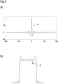
- An example of this is shown in Figure 5a .
- the signal section 11 is designed in the form of a cardinal sine. An offset is advantageously added to this signal section 11 so that all signal values are positive.
- Figure 5b shows the frequency spectrum of this signal section 11.
- I represents the ideal frequency curve for a temporally unlimited course of a cardinal sine of the signal section 11.
- II represents the real spectrum for a broad sine cardinal curve.
- the or each transmitter 4 emits, preferably at regular intervals, light beams 3 in the form of defined signal sections 11, as shown for example in Figure 5a
- a spectral decomposition of received signals 6a registered at the receiver(s) 6 is carried out.
- a frequency analysis is carried out in the evaluation unit 9 in such a way that it is checked whether frequency lines stored in the evaluation unit 9, in particular as target values, are present in the spectrally decomposed received signal 6a. This provides a safe and reliable statement as to whether the light beams 3 of a transmitter 4 are guided over a measuring path to the associated receiver 6 or not, which is used to generate the object detection signal.
- Figure 6 shows a first example of a transmitter control for the generation of signal sections 11, which are transmitted by transmitters 4.1 - 4.N of the light curtain according to Figure 2 are emitted.
- a controller 12 in the form of an ASIC, FPGA or processor reads signal sections 11 from a table and feeds them to a signal packet generator 13, which generates corresponding digital signals. These are converted into analog signals in a digital-analog converter 14, which are fed to a post-processing unit 15, in which in particular any necessary offset is added to the signal sections 11.
- the analog signals processed in this way are fed to the transmitters 4.1 - 4.N, with each transmitter 4.1-4.N being assigned an amplifier 16.1. - 16.N to amplify these signals.
- Figure 7 shows another example of a transmitter control. This differs from the embodiment according to Figure 6 in that only one amplifier 16 is provided, which is connected to the individual transmitters 4.1-4.N one after the other in order to amplify their signals. In addition, in this case there is no post-processing unit 15. Necessary offsets or post-processing are then already taken into account in the stored signal sections 11.
- the sensor controls according to the Figures 6 and 7 are part of the transmitter control 8 of the optical sensor 1 according to Figure 2 .
- Figure 8 shows a first example of a receiving-side circuit arrangement for the optical sensor 1 according to Figure 2 .
- Receive signals 6a generated in the receivers 6.1 - 6.N are amplified in an amplifier 17.1.- 17.N and then fed to a preprocessing unit 18. There, an analog preprocessing of the receive signals 6a takes place, for example in the form of high-pass, low-pass, band-pass filtering or offset correction.
- the received signals 6a are spectrally decomposed using an FFT (Fast Fourier Transformation).
- the FFT unit 19 is controlled by a controller 20.
- the spectrally decomposed received signals 6a are evaluated in an evaluator 21.
- the frequency signals generated in the FFT unit 19 are fed to the evaluator 21.
- the controller 20 and the evaluator 21 are components of the evaluation unit 9.
- Figure 9a shows the periodic repetition of a signal section 11 with a period Tp.
- a transmitter 4.1-4.N periodically emits signal sections 11 as in Figure 9a and 10a respectively.
- the FFT unit 19 is used to calculate the figure 9b
- the spectral decomposition of the received signal 6a shown is obtained. This is sampled and evaluated by the evaluator 21. The sampling frequency of the sampling is greater than the frequency components of the spectrally decomposed received signal 6a.
- the frequency lines of the spectrally decomposed received signal 6a ( Figure 9b) recorded in this way correspond to an expectation stored in the evaluation unit 9 in the form of target values.
- the expectations can be frequency ranges in which frequency lines should lie and/or amplitude ranges and/or phase ranges of such frequency lines.
- the evaluator 21 thus generates as an output signal that the measuring section of this beam axis is free/interrupted.
- the evaluation unit 9 If all beam axes are registered as free in this way, the evaluation unit 9 generates a switching signal with the switching state free monitoring area as an object detection signal.
- Figure 10b shows the case when not all frequency lines originating from signal sections 11 are recorded. Instead, however, frequency lines b are recorded due to external interference.
- the evaluation in the evaluation unit 9 is carried out in a fault-tolerant manner in such a way that not all frequency lines of the spectrum of the signal sections 11 have to be evaluated. Frequency lines caused by external radiation can also be accepted. If this condition is met in the case of Figure 10b fulfilled, the beam axis is still considered free.
- the beam axis is considered to be interrupted and the switching signal assumes the switching state "object present".
- Figure 11 shows a variant of the embodiment of the Figure 10 .
- the embodiment according to Figure 11 differs from the embodiment according to Figure 10 in that only one amplifier 17 is present, in which the received signals 6a of all receivers 6.1 - 6.N are amplified.
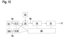
- FIG 12 shows a further variant of the embodiment according to Figure 10 .
- the received signals 6a of the receivers 6.1 - 6.N amplified in the amplifier 17 are fed to a mixer 22, whereby the received signals are transformed into a low-frequency range by multiplying them by a mixing frequency f o generated in a frequency generator 23.
- Complex-valued mixing methods which retain the phase information of the useful signal are particularly advantageous.
- the mixer 22 can have an analog circuit or a digital circuit, such as a Hilbert mixer.
- the computing time required for signal evaluation can be reduced.
- the received signals 6a or the low-frequency received signals 6b can be subsampled, ie sampled at a significantly lower frequency.
Landscapes
- Physics & Mathematics (AREA)
- Life Sciences & Earth Sciences (AREA)
- General Life Sciences & Earth Sciences (AREA)
- General Physics & Mathematics (AREA)
- Geophysics (AREA)
- Geophysics And Detection Of Objects (AREA)
Priority Applications (1)
| Application Number | Priority Date | Filing Date | Title |
|---|---|---|---|
| EP23163987.3A EP4435478A1 (fr) | 2023-03-24 | 2023-03-24 | Capteur optique et procédé de fonctionnement d'un capteur optique |
Applications Claiming Priority (1)
| Application Number | Priority Date | Filing Date | Title |
|---|---|---|---|
| EP23163987.3A EP4435478A1 (fr) | 2023-03-24 | 2023-03-24 | Capteur optique et procédé de fonctionnement d'un capteur optique |
Publications (1)
| Publication Number | Publication Date |
|---|---|
| EP4435478A1 true EP4435478A1 (fr) | 2024-09-25 |
Family
ID=85726118
Family Applications (1)
| Application Number | Title | Priority Date | Filing Date |
|---|---|---|---|
| EP23163987.3A Pending EP4435478A1 (fr) | 2023-03-24 | 2023-03-24 | Capteur optique et procédé de fonctionnement d'un capteur optique |
Country Status (1)
| Country | Link |
|---|---|
| EP (1) | EP4435478A1 (fr) |
Cited By (1)
| Publication number | Priority date | Publication date | Assignee | Title |
|---|---|---|---|---|
| CN121276645A (zh) * | 2025-12-08 | 2026-01-06 | 四川井宇科技有限公司 | 一种站端继电保护压板状态识别方法及设备 |
Citations (3)
| Publication number | Priority date | Publication date | Assignee | Title |
|---|---|---|---|---|
| US20210302617A1 (en) * | 2018-08-07 | 2021-09-30 | Trinamix Gmbh | Device and method for optically surveilling at least one area |
| US20220137255A1 (en) * | 2020-10-29 | 2022-05-05 | Banner Engineering Corp. | Frequency domain opposed-mode photoelectric sensor |
| DE202022100571U1 (de) * | 2022-02-02 | 2022-08-22 | Leuze Electronic Gmbh + Co. Kg | Lichtschrankenanordnung |
-
2023
- 2023-03-24 EP EP23163987.3A patent/EP4435478A1/fr active Pending
Patent Citations (3)
| Publication number | Priority date | Publication date | Assignee | Title |
|---|---|---|---|---|
| US20210302617A1 (en) * | 2018-08-07 | 2021-09-30 | Trinamix Gmbh | Device and method for optically surveilling at least one area |
| US20220137255A1 (en) * | 2020-10-29 | 2022-05-05 | Banner Engineering Corp. | Frequency domain opposed-mode photoelectric sensor |
| DE202022100571U1 (de) * | 2022-02-02 | 2022-08-22 | Leuze Electronic Gmbh + Co. Kg | Lichtschrankenanordnung |
Cited By (1)
| Publication number | Priority date | Publication date | Assignee | Title |
|---|---|---|---|---|
| CN121276645A (zh) * | 2025-12-08 | 2026-01-06 | 四川井宇科技有限公司 | 一种站端继电保护压板状态识别方法及设备 |
Similar Documents
| Publication | Publication Date | Title |
|---|---|---|
| DE4141468C2 (de) | Optische Sensoranordnung und Verfahren zu deren Betrieb | |
| DE102014226073A1 (de) | Verfahren und Vorrichtung zum Betreiben eines Radarsystems eines Kraftfahrzeugs | |
| DE4141469C2 (de) | Verfahren zum Betrieb einer optischen Sensoranordnung zur Feststellung von in einem Überwachungsbereich vorhandenen Gegenständen sowie eine solche optische Sensoranordnung | |
| EP3154233B1 (fr) | Appareil de mesure et procédé de mesure destinés à la détection de doubles émissions simultanées | |
| DE102017211707A1 (de) | Verfahren und LIDAR-Vorrichtung zum Abtasten eines Abtastbereiches mit mindestens zwei pulskodierten Strahlen | |
| EP2680029A1 (fr) | Procédé de mesure de distance et dispositif de mesure de distance | |
| EP4435478A1 (fr) | Capteur optique et procédé de fonctionnement d'un capteur optique | |
| DE10355008A1 (de) | Verfahren zur Verarbeitung eines Empfangssignals und optischer Sensor | |
| EP2278359B1 (fr) | Procédé de fonctionnement de barrières lumineuses | |
| DE102010020023A1 (de) | Verfahren und Vorrichtung zur Rauschoptimierung eines Echosignals zur Fahrzeugumfelderfassung sowie zugehörige Vorrichtung zur Fahrzeugumfelderfassung | |
| EP1798577B1 (fr) | Dispositif électro-optique et méthode d'operation d'un tel dispositif | |
| EP3147694B1 (fr) | Procede de fonctionnement d'un capteur photoelectrique et capteur photoelectrique | |
| EP2983009A1 (fr) | Fonctionnement d'un capteur optoélectronique selon un procédé d'émission d'impulsions lumineuses | |
| EP4224218B1 (fr) | Ensemble barrière lumineuse | |
| DE19924733A1 (de) | Gerät zum Lesen oder Beschreiben optischer Aufzeichnungsträger | |
| EP3614182B1 (fr) | Système de barrière lumineuse | |
| DE4135158C2 (de) | Verfahren zum Erfassen und Korrigieren von Impulsstörungen in einem lernbaren Universal-Fernbedienungsgerät | |
| DE19506390A1 (de) | Entfernungsmeßgerät | |
| EP4339653B1 (fr) | Capteur optique | |
| EP4414754A1 (fr) | Capteur optique | |
| DE102011000857A1 (de) | Optoelektronischer Sensor und Verfahren zur Erfassung von Objekten | |
| DE102011014195A1 (de) | Optischer Sensor | |
| DE3920169A1 (de) | Einrichtung und verfahren zur untersuchung des daempfungsverlaufs eines lichtwellenleiters | |
| EP3822667B1 (fr) | Agencement de barrières lumineuses | |
| DE102019219330A1 (de) | Einrichtung zum Erzeugen von Testdaten zum Testen einer Distanzbestimmung bei einer optischen Laufzeitmessung, Messeinrichtung zum Testen einer Distanzbestimmung bei einer optischen Laufzeitmessung und Verfahren zum Erzeugen von Testdaten zum Testen einer Distanzbestimmung bei einer optischen Laufzeitmessung |
Legal Events
| Date | Code | Title | Description |
|---|---|---|---|
| PUAI | Public reference made under article 153(3) epc to a published international application that has entered the european phase |
Free format text: ORIGINAL CODE: 0009012 |
|
| STAA | Information on the status of an ep patent application or granted ep patent |
Free format text: STATUS: REQUEST FOR EXAMINATION WAS MADE |
|
| 17P | Request for examination filed |
Effective date: 20230920 |
|
| AK | Designated contracting states |
Kind code of ref document: A1 Designated state(s): AL AT BE BG CH CY CZ DE DK EE ES FI FR GB GR HR HU IE IS IT LI LT LU LV MC ME MK MT NL NO PL PT RO RS SE SI SK SM TR |
|
| P01 | Opt-out of the competence of the unified patent court (upc) registered |
Free format text: CASE NUMBER: APP_53496/2024 Effective date: 20240926 |
|
| STAA | Information on the status of an ep patent application or granted ep patent |
Free format text: STATUS: EXAMINATION IS IN PROGRESS |
|
| 17Q | First examination report despatched |
Effective date: 20260113 |