EP3015068A1 - Dispositif et procédé pour acquérir une image de fusion - Google Patents
Dispositif et procédé pour acquérir une image de fusion Download PDFInfo
- Publication number
- EP3015068A1 EP3015068A1 EP13890324.0A EP13890324A EP3015068A1 EP 3015068 A1 EP3015068 A1 EP 3015068A1 EP 13890324 A EP13890324 A EP 13890324A EP 3015068 A1 EP3015068 A1 EP 3015068A1
- Authority
- EP
- European Patent Office
- Prior art keywords
- image
- target
- signal
- acquiring
- probing
- Prior art date
- Legal status (The legal status is an assumption and is not a legal conclusion. Google has not performed a legal analysis and makes no representation as to the accuracy of the status listed.)
- Withdrawn
Links
Images


Classifications
-
- A—HUMAN NECESSITIES
- A61—MEDICAL OR VETERINARY SCIENCE; HYGIENE
- A61B—DIAGNOSIS; SURGERY; IDENTIFICATION
- A61B5/00—Measuring for diagnostic purposes; Identification of persons
- A61B5/0033—Features or image-related aspects of imaging apparatus, e.g. for MRI, optical tomography or impedance tomography apparatus; Arrangements of imaging apparatus in a room
- A61B5/0035—Features or image-related aspects of imaging apparatus, e.g. for MRI, optical tomography or impedance tomography apparatus; Arrangements of imaging apparatus in a room adapted for acquisition of images from more than one imaging mode, e.g. combining MRI and optical tomography
-
- A—HUMAN NECESSITIES
- A61—MEDICAL OR VETERINARY SCIENCE; HYGIENE
- A61B—DIAGNOSIS; SURGERY; IDENTIFICATION
- A61B5/00—Measuring for diagnostic purposes; Identification of persons
- A61B5/0059—Measuring for diagnostic purposes; Identification of persons using light, e.g. diagnosis by transillumination, diascopy, fluorescence
-
- A—HUMAN NECESSITIES
- A61—MEDICAL OR VETERINARY SCIENCE; HYGIENE
- A61B—DIAGNOSIS; SURGERY; IDENTIFICATION
- A61B5/00—Measuring for diagnostic purposes; Identification of persons
- A61B5/0093—Detecting, measuring or recording by applying one single type of energy and measuring its conversion into another type of energy
- A61B5/0095—Detecting, measuring or recording by applying one single type of energy and measuring its conversion into another type of energy by applying light and detecting acoustic waves, i.e. photoacoustic measurements
-
- A—HUMAN NECESSITIES
- A61—MEDICAL OR VETERINARY SCIENCE; HYGIENE
- A61B—DIAGNOSIS; SURGERY; IDENTIFICATION
- A61B8/00—Diagnosis using ultrasonic, sonic or infrasonic waves
- A61B8/44—Constructional features of the ultrasonic, sonic or infrasonic diagnostic device
- A61B8/4416—Constructional features of the ultrasonic, sonic or infrasonic diagnostic device related to combined acquisition of different diagnostic modalities, e.g. combination of ultrasound and X-ray acquisitions
-
- A—HUMAN NECESSITIES
- A61—MEDICAL OR VETERINARY SCIENCE; HYGIENE
- A61B—DIAGNOSIS; SURGERY; IDENTIFICATION
- A61B8/00—Diagnosis using ultrasonic, sonic or infrasonic waves
- A61B8/52—Devices using data or image processing specially adapted for diagnosis using ultrasonic, sonic or infrasonic waves
- A61B8/5207—Devices using data or image processing specially adapted for diagnosis using ultrasonic, sonic or infrasonic waves involving processing of raw data to produce diagnostic data, e.g. for generating an image
-
- A—HUMAN NECESSITIES
- A61—MEDICAL OR VETERINARY SCIENCE; HYGIENE
- A61B—DIAGNOSIS; SURGERY; IDENTIFICATION
- A61B8/00—Diagnosis using ultrasonic, sonic or infrasonic waves
- A61B8/52—Devices using data or image processing specially adapted for diagnosis using ultrasonic, sonic or infrasonic waves
- A61B8/5215—Devices using data or image processing specially adapted for diagnosis using ultrasonic, sonic or infrasonic waves involving processing of medical diagnostic data
- A61B8/5238—Devices using data or image processing specially adapted for diagnosis using ultrasonic, sonic or infrasonic waves involving processing of medical diagnostic data for combining image data of patient, e.g. merging several images from different acquisition modes into one image
- A61B8/5246—Devices using data or image processing specially adapted for diagnosis using ultrasonic, sonic or infrasonic waves involving processing of medical diagnostic data for combining image data of patient, e.g. merging several images from different acquisition modes into one image combining images from the same or different imaging techniques, e.g. color Doppler and B-mode
-
- H—ELECTRICITY
- H04—ELECTRIC COMMUNICATION TECHNIQUE
- H04N—PICTORIAL COMMUNICATION, e.g. TELEVISION
- H04N5/00—Details of television systems
- H04N5/222—Studio circuitry; Studio devices; Studio equipment
- H04N5/262—Studio circuits, e.g. for mixing, switching-over, change of character of image, other special effects ; Cameras specially adapted for the electronic generation of special effects
- H04N5/2624—Studio circuits, e.g. for mixing, switching-over, change of character of image, other special effects ; Cameras specially adapted for the electronic generation of special effects for obtaining an image which is composed of whole input images, e.g. splitscreen
-
- A—HUMAN NECESSITIES
- A61—MEDICAL OR VETERINARY SCIENCE; HYGIENE
- A61B—DIAGNOSIS; SURGERY; IDENTIFICATION
- A61B5/00—Measuring for diagnostic purposes; Identification of persons
- A61B5/0059—Measuring for diagnostic purposes; Identification of persons using light, e.g. diagnosis by transillumination, diascopy, fluorescence
- A61B5/0071—Measuring for diagnostic purposes; Identification of persons using light, e.g. diagnosis by transillumination, diascopy, fluorescence by measuring fluorescence emission
Definitions
- This disclosure relates to a medical image technique for diagnosis, analysis and treatment, and more particularly, to a probe structure, an imaging device and an imaging method for acquiring a fusion image capable of providing pathologic and anatomical information simultaneously based on various medical image techniques.
- An ultrasound (US) imaging device is equipment for imaging structure and characteristics of an observation area by applying an ultrasound signal to an observation area in a human body with an ultrasound probe, receiving a returning ultrasound signal reflected by tissues, and extracting information included in the signal.
- the US imaging device may advantageously obtain an image in real time without any harm to the human body at low costs in comparison to other medical imaging systems such as X-ray, CT, MRI, PET or the like.
- a photoacoustic (PA) imaging device applies photon to an observation area in a human body, receives an ultrasound signal directly generated from photons absorbed in tissues, and extracts image information from the signal. This peculiar situation where photons are absorbed in tissues to generate an ultrasound happens since the tissues are heated while absorbing the photons. Thus, if a pulse laser is irradiated to the absorptive tissue structure, the tissue temperature changes, and as a result the tissue structure is expanded. A pressure wave is propagated outwards from the expanded structure, and the pressure wave may be probed using an ultrasound transducer.
- the photoacoustic image has advantages in that an image may be obtained based on an optical absorption contrast ratio while ensuring resolution to the level of ultrasound, costs are very low in comparison to MRI, and patents are not exposed to ionizing radiation.
- a fluorescent (FL) imaging device uses a principle that, cells or bacteria where a fluorescent protein gene is expressed are marked or put into a living body and a light source of a specific wavelength is irradiated thereto, the cells or tissues of the living body or a fluorescent material in the living body absorbs and excites the light irradiated from the outside to emit a light of a specific wavelength, and this light is probed and imaged.
- the fluorescent protein gene required for acquiring a fluorescent image green fluorescent protein (GFP), red fluorescent protein (RFP), blue fluorescent protein (BFP) and yellow fluorescent protein (YEP) or enhanced GFP (EGFP) which is a variety of GFP are widely used, and more diverse fluorescent proteins with increased brightness are being developed.
- the fluorescent image is generally acquired using a charged coupled device (CCD) camera, which allows rapid acquisition of a fluorescent image, and animals such as guinea pig are not sacrificed.
- CCD charged coupled device
- Such medical diagnosis imaging devices have different observation areas and characteristics, and thus different kinds of devices should be applied to a single observation area depending on purpose and situation.
- these imaging techniques may be utilized together.
- the present disclosure is directed to overcoming the limit of the existing technique in which existing medical imaging devices are individually utilized at diagnosis and medical sites. Also, in the existing technique, due to the absence of a technical measure for simultaneously monitoring a single region in a multilateral way, medical images for an observation area are acquired sporadically depending on a target to be monitored and a purpose of monitoring, and then the images should be analyzed individually by experts. But, the present disclosure is directed to solving such inconvenience.
- a device for acquiring an image comprising: a sound source configured to apply an ultrasound signal for an ultrasound (US) image to a target; a light source configured to apply an optical signal for a photoacoustic (PA) image and a fluorescent (FL) image to the target; a sound probing unit configured to receive the ultrasound signal generated by the sound source and the photoacoustic signal generated by the light source from the target; a light probing unit configured to receive the optical signal generated by the light source from the target; and an image generating unit configured to generate a fusion image including image information with different probing planes with respect to the target by using at least two signals of the received ultrasound signal, the received photoacoustic signal and the received optical signal.
- a sound source configured to apply an ultrasound signal for an ultrasound (US) image to a target
- a light source configured to apply an optical signal for a photoacoustic (PA) image and a fluorescent (FL) image to the target
- a sound probing unit configured to receive the ultrasound signal generated by the sound source and
- the image generating unit may generate a single fusion image by: generating a depth image of the target from the received ultrasound signal or the received photoacoustic signal, generating a planar image of the target from the received optical signal, and mapping the generated depth image and the generated planar image.
- the image generating unit may determine a feature point from each of the images with different probing planes, and map the determined feature points to generate an image where a relation among the images is visually matched and displayed.
- the sound probing unit may be located adjacent to the target, and the light probing unit may be installed to be located relatively far from the target in comparison to the sound probing unit.
- the sound probing unit and the light probing unit may be installed along different axes to prevent signal interference from each other.
- the device may further include a switch for shifting operations of the sound probing unit and the light probing unit to each other, and a signal corresponding to each probing unit may be received according to a manipulation of a user on the switch.
- a device for acquiring an image comprising: a sound source configured to apply an ultrasound signal for an ultrasound image to a target; a light source configured to apply an optical signal for a photoacoustic image and a fluorescent image to the target; a sound probing unit configured to receive the ultrasound signal generated by the sound source and the photoacoustic signal generated by the light source from the target; a light probing unit configured to receive the optical signal generated by the light source from the target; a location control unit configured to adjust physical locations of the sound probing unit and the light probing unit; and an image generating unit configured to generate a fusion image including image information with different probing planes with respect to the target by using at least two signals of the received ultrasound signal, the received photoacoustic signal and the received optical signal according to the adjusted locations.
- the image generating unit may generate a single fusion image by: generating a three-dimensional image by moving the sound probing unit along a surface of the target according to the control of the location control unit to laminate a depth image of the target from the received ultrasound signal or the received photoacoustic signal, generating a planar image of the target by fixing the location of the light probing unit according to the control of the location control unit, and mapping the generated three-dimensional image and the generated planar image in consideration of the adjusted location.
- the location control unit may move the sound probing unit in a longitudinal direction along a surface of the target based on the light probing unit to guide successive generation of depth images corresponding to the planar image by the light probing unit.
- the sound probing unit may be located adjacent to the target, the light probing unit may be installed to be located relatively far from the target in comparison to the sound probing unit, and the sound probing unit may receive a sound signal from the target while changing the location thereof according to the control of the location control unit.
- the device may further include an optical and/or acoustical transparent front which is adjacent to the target and has permeability with respect to an optical signal and a sound signal.
- a method for acquiring an image comprising: applying an ultrasound signal for an ultrasound image or an optical signal for a photoacoustic image to a target, and receiving an ultrasound signal or photoacoustic signal corresponding to a signal applied from the target; applying an optical signal for a fluorescent image to the target, and receiving an optical signal from the target; and generating a fusion image including image information with different probing planes with respect to the target by using at least two signals of the received ultrasound signal, the received photoacoustic signal and the received optical signal, wherein the fusion image includes a depth image generated from the received ultrasound signal or the received photoacoustic signal, a planar image generated from the received optical signal and mapping information between the depth image and the planar image.
- the method may further include displaying the generated fusion image on a display device, and the depth image and the planar image included in the fusion image may be shifted to each other according to a manipulation of a user to be displayed simultaneously or in order.
- the method may further include generating a three-dimensional image by moving a probing unit for receiving the ultrasound signal or photoacoustic signal in a longitudinal direction along a surface of the target based on the probing unit for the fluorescent image, so that the depth image is successively laminated corresponding to the planar image, and the generating of a fusion image may generate a single fusion image by mapping the generated three-dimensional image and the generated planar image in consideration of the adjusted location.
- the method may further include determining a feature point from each of the images with different probing planes, and mapping the determined feature points, and the generating of a fusion image may generate an image in which a relation among the images is visually matched and displayed.
- the method may further include: displaying the ultrasound image, the photoacoustic image and the fluorescent image on a display device simultaneously; and generating an overlaying image in which at least two images selected by a user are overlaid, and displaying the overlaying image on the display device.
- the method may further include: receiving an adjustment value for a location of the image, a parameter for the image and transparency of the image from the user; and generating an image changed according to the input adjustment value and displaying the changed image on the display device.
- the embodiments of the present disclosure allows easier analysis of images by providing a probe structure, which may utilize various medical imaging techniques using an ultrasound image, a photoacoustic image and a fluorescent image simultaneously, provide pathologic information, anatomical information and functional information for a single observation area in a multilateral way by generating a fusion image based on planar image information and depth image information having different probing planes with respect to the observation target, and generate a fusion image through simple user manipulation at a medical site.
- the present disclosure provides a device for acquiring an image, which includes: a sound source configured to apply an ultrasound signal for an ultrasound (US) image to a target; a light source configured to apply an optical signal for a photoacoustic (PA) image and a fluorescent (FL) image to the target; a sound probing unit configured to receive the ultrasound signal generated by the sound source and the photoacoustic signal generated by the light source from the target; a light probing unit configured to receive the optical signal generated by the light source from the target; and an image generating unit configured to generate a fusion image including image information with different probing planes with respect to the target by using at least two signals of the received ultrasound signal, the received photoacoustic signal and the received optical signal.
- a sound source configured to apply an ultrasound signal for an ultrasound (US) image to a target
- a light source configured to apply an optical signal for a photoacoustic (PA) image and a fluorescent (FL) image to the target
- a sound probing unit configured to receive the ultrasound signal generated
- a biological tissue causes a radiative process and a nonradiative process through a photoacoustic coefficient, and a fluorescent image and a photoacoustic image are formed by means of different process bases through absorbed optical energy.
- the embodiments of the present disclosure allow observing the degree of light absorption and the generation of radiative/nonradiative process of a tissue, thereby proposing a system structure which may obtain an optical characteristic of the tissue as a more accurate quantitative index and provide elastic ultrasound image (elastography) and color flow imaging by processing the ultrasound signal.
- the embodiments of the present disclosure may provide a quantitative index with high contrast in an application using a contrast agent which is reactive with a single imaging technique or multiple imaging techniques, and propose individual information for various imaging techniques or applications used in existing ultrasound, photoacoustic and fluorescent imaging, or a structure required for developing a new application by combining such individual information.
- a fusion probe and system structure capable of performing ultrasound, photoacoustic and fluorescent imaging techniques to a single tissue and processing them in association with each other in a bundle.
- an auxiliary system structure for improving the shape of the fusion probe, the structure of the system and the quality of the image.
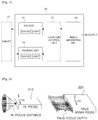
- Fig. 1 is a block diagram showing a basic structure of a device 20 for acquiring an image (hereinafter, also referred to as an image acquiring device), employed in embodiments of the present disclosure, and the image acquiring device 20 includes a source 21 and a probing unit 24 used adjacent to an observation target 10, and an image generating unit 29 respectively electrically connected thereto.
- an image acquiring device for acquiring an image
- the image acquiring device 20 includes a source 21 and a probing unit 24 used adjacent to an observation target 10, and an image generating unit 29 respectively electrically connected thereto.
- the source 21 may be classified into a sound source and a light source depending on the kind of generated signal.
- the sound source applies an ultrasound signal for an ultrasound (US) image to a target 10
- the light source applies an optical signal for a photoacoustic (PA) image and a fluorescent (FL) image to the target 10.
- US ultrasound
- PA photoacoustic
- FL fluorescent
- the probing unit 24 may be classified into a sound probing unit and a light probing unit depending on the kind of received signal.
- the sound probing unit receives an ultrasound signal generated by the sound source or a photoacoustic signal generated by the light source from the target 10, and the light probing unit receives an optical signal generated by the light source from the target 10.
- the source 21 and the probing unit 24 are depicted separately in a functional view, but they may also be implemented as a physically integrated unit.
- the source 21 and the probing unit 24 may be implemented to be included in the same component.
- the ultrasound image and the photoacoustic image may be implemented in the same hardware since a carrier signal to be probed from the target 10 is an ultrasound signal.
- a detailed source of the photoacoustic image is a pulsed wave, different from the source of the ultrasound image.
- the fluorescent image applies an optical signal, in more detail a continuous wave and receives an optical signal emitted from a tissue of the target 10 by using a CCD camera, which allows implementation in single hardware.
- the sound probing unit and the light probing unit have different minimum distances to the observation target 10 depending on signal observation characteristics.
- the sound probing unit may be located adjacent to the observation target 10, and the light probing unit may be installed to be located relatively far from the observation target 10 in comparison to the sound probing unit. This is because a probe based on a sound signal like the ultrasound image is used in contact with the observation target 10, and a probe based on an optical signal like the fluorescent image is used at a predetermined distance to observe a planar structure like the surface of the observation target 10.
- the image generating unit 29 generates a fusion image including image information with different probing planes with respect to the target 10 by using at least two signals of the ultrasound signal, the photoacoustic signal and the optical signal received from the probing unit 24.
- a single fusion image including various kinds of information may be generated by collecting a plurality of image information with different probing planes, and the detailed configuration of each embodiment will be described later with reference to the drawings.
- the image acquiring device of Fig. 1 may selectively include a location control unit 27 between the source 21 and/or the probing unit 24 and the image generating unit 29.
- the location control unit 27 adjusts physical locations of the sound probing unit and the light probing unit and guides the image generating unit 29 to generate a fusion image from the signals received according to the locations adjusted by the location control unit 27.
- the image generating unit 29 moves the probing unit 24, particularly the sound probing unit, along the surface of the target 10 according to the control of the location control unit 27, so that a depth image of the target 10 is laminated from the received ultrasound signal or photoacoustic signal to generate a three-dimensional image.
- the image generating unit 29 may generate a planar image of the target 10 by fixing the location of the probing unit 24, particularly the light probing unit, according to the control of the location control unit 27, and may generate a single fusion image by mapping the three-dimensional image and the planar image generated in consideration of a finally adjusted location.
- the location control unit 27 is required for generating a three-dimensional image from the depth image by controlling the location of the probing unit 24.
- a user may directly moves the probing unit 24 along the surface of the target 10 so that the light probing unit is located at the same portion as the acquired ultrasound signal or photoacoustic signal to acquire a fluorescent planar image, thereby providing a single fusion image by means of software image mapping.
- Data of each imaging technique used in the above image mapping procedure may employ a high-contrast imaging method, used in individual techniques, to improve the quality of image.
- the ultrasound image may utilize, for example, harmonic, perfusion imaging, synthetic aperture, planar wave, blood flow imaging, adaptive beam focusing or the like.
- the photoacoustic image may utilize, for example, adaptive beam focusing, spectroscopy or the like.
- the fluorescent image may utilize, for example, stereo 3D imaging, spectroscopy, wavelength separating or the like.
- the image generating unit 29 may determine a feature point from each of images with different probing planes and map the determined feature point, thereby generating an image where a relation of the images may be visually matched and displayed.
- an image processing technique for extracting feature points from a plurality of images and mapping the feature points may be utilized.
- mapping images basically, an axis of one image is specified based on the target 10, and images are connected on the basis of the specified axis, so that a relation of common features is displayed.
- a three-dimensional coordinate system for the target 10 is assumed, a display direction of the image with respect to x-, y- and z-directions of the coordinate system is set, and the images are mapped based on the feature point to generate a matched image.
- Fig. 2 is a diagram for illustrating structural characteristics of two kinds of probes, employed in embodiments of the present disclosure, where a fluorescent image probe (FL probe) 210 for generating a planar image of a target and an photoacoustic/ultrasound image array probe (PAUS array probe) 220 for generating a depth image of a target are depicted.
- FL probe fluorescent image probe
- PAUS array probe photoacoustic/ultrasound image array probe
- each probe may be implemented to include a signal applying unit (source) and a signal receiving unit as a single unit, as described above.
- the FL probe 210 includes a light applying unit capable of applying light and a CCD sensor capable of receiving a fluorescent signal generated from a target tissue to acquire a fluorescent (FL) image and a white light (WL) image
- the PAUS array probe 220 includes a light applying unit capable of transmitting a pulsed laser and an array transducer capable of receiving an ultrasound to acquire data of a photoacoustic image and an ultrasound image.
- the FL light applying unit and the PAUS light applying unit may be designed to be integrated into a single component or separated from each other.
- the image generating unit proposed in the embodiments of the present disclosure generates a depth image of the target from the ultrasound signal or photoacoustic signal received through the sound probing unit, generate a planar image of the target from the optical signal received through the light probing unit, and maps the generated depth image and the generated planar image to generate a single fusion image.
- Figs. 3a to 3d are diagrams showing various probe structures, which may be utilized in the image acquiring device according to the embodiments of the present disclosure, and these structures may be utilized in two ways briefly..
- Figs. 3a and 3b show a probe structure for real-time PAUS and FL imaging, where the PAUS probe and the FL probe are implemented to be fixed in a single probe structure 310, and a PAUS image and a FL image may be output alternately according to a manipulation (PUSH/RELEASE) of the FL button 320 which corresponds to a switch for shifting operations of the sound probing unit and the light probing unit to each other.
- the image acquired through the probe structure 310 may be provided to an imaging system through a connector via a connection unit 350 having a cable.
- the connection unit 350 may further include a mechanical arm for operating the probe structure 310 at a position closer to the observation target.
- the sound probing unit (PAUS array probe) and the light probing unit (WL/FL probe) may be installed along different axes to prevent signal interference from each other.
- Figs. 3c and 3d show a fusion probe structure capable of displaying a PAUS image and a FL image at the same location of a human body in a fused state, and the structure includes a movable PAUS probe and a stationary WL/FL probe in a single probe structure 330.
- the PAUS probe moves vertically by means of a mechanically movable scanner to acquire data of a three-dimensional image, and the FL probe is located at a rear position of the fusion probe to acquire a planar image of the image region.
- the image acquiring device proposed in the embodiments of the present disclosure may move the sound probing unit (PAUS array probe) in a longitudinal direction along the surface of the target based on the light probing unit (WL/FL probe) by using the location control unit (not shown), thereby guiding a depth image to be successively generated corresponding to the planar image by the light probing unit (WL/FL probe).
- PAUS array probe sound probing unit
- WL/FL probe location control unit
- the sound probing unit may be located adjacent to the target, the light probing unit (WL/FL probe) may be installed to be located relatively far from the target in comparison to the sound probing unit (PAUS array probe), and the sound probing unit (PAUS array probe) may receive a sound signal from the target while changing its location according to the control of the location control unit (not shown).
- the inside of the probe may be filled with a coupler capable of transmitting light without loss and allowing ultrasound permeation
- the surface of the probe may be made of a material allowing permeation of ultrasound and light.
- the probe structure 330 depicted in Figs. 3c and 3d may include an optical/acoustical transparent front 340 which is adjacent to the target and has permeability with respect to optical signals and sound signals.
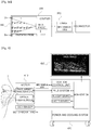
- Fig. 4 is a diagram showing a fusion image diagnosis system including the image acquiring device according to an embodiment of the present disclosure, and the fusion image diagnosis system includes a multi-modal probe 410 having a plurality of sources and probes, an image processing system 420 and a display device 430.
- the image processing system 420 includes a workstation for controlling the overall fusion image diagnosis system, a PAUS system for treating signals of photoacoustic and ultrasound images, a FL light source for applying an optical energy for the fluorescent image and the photoacoustic image, and a probe location control unit (probe positioner) capable of controlling a location of the probe as demanded by the user, and acquires bio data in various aspects through the multi-modal probe 410 serving as a fusion probe.
- a workstation for controlling the overall fusion image diagnosis system
- a PAUS system for treating signals of photoacoustic and ultrasound images
- a FL light source for applying an optical energy for the fluorescent image and the photoacoustic image
- a probe location control unit probe positioner
- the multi-modal probe 410 includes a PAUS linear transducer for receiving photoacoustic and ultrasound signals, an optic fiber bundle for applying an optical energy transmitted from a main body, and a CCD sensor for acquiring fluorescent data generated from the human body, and transmits the acquired data to the image processing system 420.
- the image processing system 420 performs image restoration based on the received data and then displays the restored image on the display device 430.
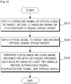
- Fig. 5 is a flowchart for illustrating a method for acquiring an image (hereinafter, also referred to as an image acquiring method) according to an embodiment of the present disclosure, which includes steps respectively corresponding to operations of the components of the image acquiring device depicted in Fig. 1 . Therefore, each process will be briefly described based on the image processing flow in order to avoid unnecessary duplicated explanations.
- the image acquiring device applies an ultrasound signal for the ultrasound image and an optical signal for the photoacoustic image to the target, and receives an ultrasound signal or photoacoustic signal corresponding to the signal applied from the target.
- the image acquiring device applies an optical signal for the fluorescent image to the target, and receives an optical signal from the target.
- the image acquiring device generates a fusion image including image information with different probing planes for the target by using at least two signals among the ultrasound signal and the photoacoustic signal received in S510 and the optical signal received in S520.
- the fusion image may include a depth image generated from the ultrasound signal or photoacoustic signal, a planar image generated from the optical signal, and mapping information between the depth image and the planar image.
- the image acquiring method as depicted in Fig. 5 may further include a step of determining a feature point from each of images with different probing planes, mapping the determined feature points. Therefore, in the fusion image generating step S530, an image where a relation between images is visually matched and displayed may be generated.
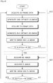
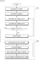
- Fig. 6 is a flowchart for illustrating a diagnosis method utilizing an image shifting switch according to an embodiment of the present disclosure, which is briefly classified into an image acquiring process 610 based on a sound signal and an image acquiring process 620 based on an optical signal.
- Fig. 6 assumes a surgery mode in which a user freely utilizes the probe structure to approach or contact a part of a body of a patient and acquires a necessary image, and a sequence of operations utilizable for subsequently acquiring a PAUS image and a FL image by using the probe structure 310 of Fig. 3a or 3b is exemplarily depicted.
- the image acquiring method may further include a process of displaying the generated fusion image on the display device, and here, an input unit for switching the depth image and the planar image included in the fusion image according to a manipulation of the user to be displayed simultaneously or subsequently may be used.
- the PAUS image acquired through the probe structure is provided, and if the user pushes the FL button, the operation may be shifted to a FL image display mode so that an image where a white light (WL) image is fused with a fluorescent (FL) image is provided to the user.
- WL white light
- FL fluorescent
- the sound signal-based image acquiring process 610 firstly acquires US frame data and generates and optimizes a US image therefrom, and also acquires PA frame data and generates and optimizes a PA image therefrom. After that, the generated PA image and US image may be mapped to generate image information in a depth direction. Now, the user presses the FL button to shift into another fluorescent image mode.
- the optical signal-based image acquiring process 620 may firstly acquire a WL image and a FL image respectively, and map a WL image and a FL image therefrom to generate image information in a front direction. Now, if the user releases the FL button, the process returns to the PAUS image acquiring process 610.
- Fig. 7 is a diagram for illustrating a method for displaying the image acquired according to the diagnosis method of Fig. 6 on a display device, and an utilizable graphic user interface (GUI) is proposed.
- GUI graphic user interface
- the PAUS image and the FL image may be alternately provided to the user in real time, and restoration information or image parameter may be set for each image mode.
- a parameter setting unit may be provided simultaneously or separately for the PAUS image and the FL image.
- characteristics of several images may be utilized together for diagnosis.
- Fig. 8 is a flowchart for illustrating a diagnosis method utilizing a stationary probe according to another embodiment of the present disclosure, which is briefly classified into an individual image acquiring process 810 and a three-dimensional image generating process 820.
- a stationary probe means a probe structure which may be fixed to an observation target and acquire a three-dimensional image, and different from a fixed probe structure, the probe for acquiring PA/US images provided in the probe structure obtains a three-dimensional image through movement, paradoxically.
- a user does not freely utilize the probe structure, but an image registration mode in which the probe structure is fixed in contact with or adjacent to a part of a body of a patient and then acquires various types of images for a single observation target is assumed, and also a sequence of operations utilizable for obtaining the PAUS image and the FL image by using the probe structure 330 of Fig. 3c or 3d is exemplarily depicted.
- the image acquiring device available for this embodiment moves the probing unit (PAUS array probe) for receiving an ultrasound signal or a photoacoustic signal in a longitudinal direction along the surface of the observation target on the basis of the probing unit (FL probe) for a fluorescent image, so that a depth image is successively laminated corresponding to the planar image to generate a three-dimensional image.
- the three-dimensional image and the planar image are mapped in consideration of the location adjusted through the location control unit to generate a single fusion image.
- a WL image and a FL image are acquired, US frame data and PA frame data are acquired along with the images, and then a PAUS image of a single frame is acquired.
- the PAUS array probe is moved in a longitudinal direction of the observation target to acquire a PAUS image of a neighboring frame.
- This depth image acquiring process for each frame is repeatedly performed until a desired number of frames (for example, until an index of a final frame reaches a preset positive integer N), and then the individual image acquiring process 810 is completed.
- the generated image includes a single surface image and N number of depth images for the interested area.
- the N number of depth images generated in the longitudinal direction is laminated to generate a single three-dimensional PAUS image.
- the generated PAUS image is optimized, and then the PAUS image and the FL image are mapped and displayed on a single display device.
- the user may reconfigure the displayed image by adjusting and resetting image parameters as necessary.
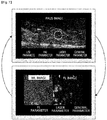
- Fig. 9 is a diagram for illustrating a method for displaying the image acquired according to the diagnosis method of Fig. 8 on a display device, and an utilizable graphic user interface (GUI) is proposed.
- GUI graphic user interface
- images may be restored according to a plurality of image modes and provided simultaneously, and thus it is possible to provide the maximum degree of freedom as required by the user on the basis of various image data acquirable through the probe structure.
- the image acquired through the probe structure may provide a WL image, a FL image, a PA image (C-plane, B-plane), a US image (B-mode, elastography, color) or the like, depending on the selection of the user before the image is acquired.
- a WL image a FL image
- PA image C-plane, B-plane
- US image B-mode, elastography, color
- the user may acquire human biometric information by freely adjusting an adjustment value for a location of the image, a parameter for the image and transparency of the individual image to be fused, by using the data of the PAUS image, the WL image and the FL image acquired through the probe structure.
- the ultrasound image, the photoacoustic image and the fluorescent image may be simultaneously displayed on the display device, and an image in which at least two images selected by the user are overlaid may be generated and displayed on the display device.
- an adjustment value for a location of the image, a parameter for the image and transparency of the image may be input by the user, and an image changed according to the input adjustment value may be generated and displayed on the display device.
- delivery of medicine and resultant effects may be quantitatively figured out by means of reaction against light, thereby allowing more quantitative evaluation of medicine effects.
- light characteristics of tissues having different clinical meanings may be more quantitatively understood to allow early diagnosis of diseases and accurate staging, which may be helpful for establishing a plane for treating a disease and actually treating the disease.
- the embodiments of the present disclosure may be applied in various ways by combining advantages of a photoacoustic/ultrasound imaging technique capable of observing a relatively greater depth for an observation target and a fluorescent imaging technique capable of observing an overall surface at a relatively smaller depth.
- a contrast agent if a contrast agent is used, characteristics of materials in or out of the contrast agent may be differently set for photoacoustic and fluorescent images, and then the distribution of the contrast agent and the degree of transfer of medicine included in the contrast agent may be quantitatively figured out.
- a motion control process of a probe structure and an image processing process for processing individual images obtained by the probe structure according to the embodiment of the present disclosure may be implemented as computer-readable codes on a computer-readable recording medium.
- the computer-readable recording medium may include any kind of storage devices where data readable by a computer system is stored.
- the computer-readable recording medium includes, for example, ROM, RAM, CD-ROM, a magnetic tape, a floppy disk and optical media, and may also be implemented in the form of carrier wave (for example, transmission through Internet).
- the computer-readable recording medium may be distributed to computer systems connected through a network so that computer-readable codes may be stored and executed in a distribution way.
- functional programs, codes and code segments for implementing the present disclosure may be easily inferred by programmers in the related art.
- a probe structure which may utilize various medical imaging techniques such as ultrasound imaging, photoacoustic imaging and fluorescent imaging simultaneously, generate a fusion image based on planar image information and depth image information with different probing planes with respect to an observation target so that pathologic information, anatomical information and functional information may be provided in a multilateral way with respect to a single observation area, and allow a user to generate a fusion image in a medical site just through a simple manipulation, thereby allowing easier image analysis.
- medical imaging techniques such as ultrasound imaging, photoacoustic imaging and fluorescent imaging simultaneously
Landscapes
- Health & Medical Sciences (AREA)
- Life Sciences & Earth Sciences (AREA)
- Engineering & Computer Science (AREA)
- Physics & Mathematics (AREA)
- Medical Informatics (AREA)
- Animal Behavior & Ethology (AREA)
- Veterinary Medicine (AREA)
- Public Health (AREA)
- Biomedical Technology (AREA)
- Heart & Thoracic Surgery (AREA)
- Biophysics (AREA)
- Molecular Biology (AREA)
- Surgery (AREA)
- Pathology (AREA)
- General Health & Medical Sciences (AREA)
- Nuclear Medicine, Radiotherapy & Molecular Imaging (AREA)
- Radiology & Medical Imaging (AREA)
- Computer Vision & Pattern Recognition (AREA)
- Acoustics & Sound (AREA)
- Multimedia (AREA)
- Signal Processing (AREA)
- Ultra Sonic Daignosis Equipment (AREA)
Applications Claiming Priority (1)
| Application Number | Priority Date | Filing Date | Title |
|---|---|---|---|
| PCT/KR2013/006943 WO2015016403A1 (fr) | 2013-08-01 | 2013-08-01 | Dispositif et procédé pour acquérir une image de fusion |
Publications (2)
| Publication Number | Publication Date |
|---|---|
| EP3015068A1 true EP3015068A1 (fr) | 2016-05-04 |
| EP3015068A4 EP3015068A4 (fr) | 2017-06-21 |
Family
ID=52431918
Family Applications (1)
| Application Number | Title | Priority Date | Filing Date |
|---|---|---|---|
| EP13890324.0A Withdrawn EP3015068A4 (fr) | 2013-08-01 | 2013-08-01 | Dispositif et procédé pour acquérir une image de fusion |
Country Status (5)
| Country | Link |
|---|---|
| US (1) | US20160192840A1 (fr) |
| EP (1) | EP3015068A4 (fr) |
| KR (1) | KR20160013893A (fr) |
| CN (1) | CN105431091A (fr) |
| WO (1) | WO2015016403A1 (fr) |
Families Citing this family (20)
| Publication number | Priority date | Publication date | Assignee | Title |
|---|---|---|---|---|
| US20160073087A1 (en) * | 2014-09-10 | 2016-03-10 | Lenovo (Singapore) Pte. Ltd. | Augmenting a digital image with distance data derived based on acoustic range information |
| JP2017047056A (ja) * | 2015-09-04 | 2017-03-09 | キヤノン株式会社 | 被検体情報取得装置 |
| KR102581189B1 (ko) * | 2016-02-05 | 2023-09-20 | 전북대학교산학협력단 | 혈전 모니터링을 위한 형광 영상 장치 및 이를 이용한 다중 영상 시스템 |
| US20190239860A1 (en) * | 2016-07-08 | 2019-08-08 | Canon Kabushiki Kaisha | Apparatus, method and program for displaying ultrasound image and photoacoustic image |
| CN107582096A (zh) * | 2016-07-08 | 2018-01-16 | 佳能株式会社 | 用于获取信息的装置、方法和存储介质 |
| CN106214130A (zh) * | 2016-08-31 | 2016-12-14 | 北京数字精准医疗科技有限公司 | 一种手持式光学成像和超声成像多模态融合成像系统与方法 |
| CN106872367B (zh) * | 2017-04-19 | 2019-09-13 | 中国科学院深圳先进技术研究院 | 一种成像系统及方法 |
| CN106983494B (zh) * | 2017-04-21 | 2021-02-09 | 中国科学院深圳先进技术研究院 | 多模态成像系统及其成像方法 |
| CN108185974A (zh) * | 2018-02-08 | 2018-06-22 | 北京数字精准医疗科技有限公司 | 一种内窥式荧光超声融合造影导航系统 |
| CN108186115B (zh) * | 2018-02-08 | 2020-04-21 | 北京数字精准医疗科技有限公司 | 手持式荧光超声融合造影导航系统 |
| CN108056821B (zh) * | 2018-02-08 | 2020-08-14 | 北京数字精准医疗科技有限公司 | 一种开放式荧光超声融合造影导航系统 |
| EP3530191A1 (fr) * | 2018-02-27 | 2019-08-28 | Leica Instruments (Singapore) Pte. Ltd. | Tête à ultrasons combinant ultrasons et optique |
| JP7205821B2 (ja) * | 2018-08-24 | 2023-01-17 | キヤノン株式会社 | システム |
| CN111727013B (zh) * | 2018-10-24 | 2023-12-22 | 中国医学科学院北京协和医院 | 一种成像方法以及成像系统 |
| CN109998599A (zh) * | 2019-03-07 | 2019-07-12 | 华中科技大学 | 一种基于ai技术的光/声双模成像眼底疾病诊断系统 |
| CN110720895A (zh) * | 2019-11-25 | 2020-01-24 | 窦少彬 | 一种基于fmt成像原理的小动物活体特征检测方法 |
| US11890142B2 (en) * | 2020-01-13 | 2024-02-06 | GE Precision Healthcare LLC | System and methods for automatic lesion characterization |
| EP4344646A1 (fr) * | 2022-09-30 | 2024-04-03 | Supersonic Imagine | Procédé et système de réglage d'un paramètre d'imagerie médicale d'un milieu |
| CN119745317A (zh) * | 2024-09-09 | 2025-04-04 | 上海深至信息科技有限公司 | 一种声光融合成像处理系统和方法 |
| CN119326439A (zh) * | 2024-09-23 | 2025-01-21 | 上海深至信息科技有限公司 | 一种基于人工智能的动态血流成像系统 |
Family Cites Families (11)
| Publication number | Priority date | Publication date | Assignee | Title |
|---|---|---|---|---|
| US20090054763A1 (en) * | 2006-01-19 | 2009-02-26 | The Regents Of The University Of Michigan | System and method for spectroscopic photoacoustic tomography |
| US20080123083A1 (en) * | 2006-11-29 | 2008-05-29 | The Regents Of The University Of Michigan | System and Method for Photoacoustic Guided Diffuse Optical Imaging |
| JP5290512B2 (ja) * | 2006-12-11 | 2013-09-18 | 日立アロカメディカル株式会社 | 画像形成システム |
| WO2008075299A1 (fr) * | 2006-12-19 | 2008-06-26 | Koninklijke Philips Electronics, N.V. | Système d'imagerie photoacoustique et ultrasonore combinée |
| CN101686827B (zh) * | 2007-01-19 | 2014-08-13 | 桑尼布鲁克健康科学中心 | 具有组合的超声和光学成像装置的成像探头 |
| EP3229010A3 (fr) * | 2007-10-25 | 2018-01-10 | Washington University in St. Louis | Microscopie photo-acoustique confocale présentant une résolution latérale optique |
| JP2011519689A (ja) * | 2008-05-07 | 2011-07-14 | インフラレデックス, インコーポレイテッド | 脈管内分析のためのマルチモーダルカテーテルシステム |
| JP5294998B2 (ja) * | 2008-06-18 | 2013-09-18 | キヤノン株式会社 | 超音波探触子、該超音波探触子を備えた光音響・超音波システム並びに検体イメージング装置 |
| KR101023657B1 (ko) * | 2008-10-29 | 2011-03-25 | 주식회사 메디슨 | 프로브장치 및 이를 구비하는 초음파 진단장치 |
| JP2013541392A (ja) * | 2010-11-08 | 2013-11-14 | コリブリ テクノロジーズ インコーポレーテッド | 低侵襲処置の間の改善された視覚化のためのシステム及び方法 |
| KR20130081067A (ko) * | 2012-01-06 | 2013-07-16 | 삼성메디슨 주식회사 | 초음파 진단 장치 및 방법 |
-
2013
- 2013-08-01 CN CN201380078630.4A patent/CN105431091A/zh active Pending
- 2013-08-01 EP EP13890324.0A patent/EP3015068A4/fr not_active Withdrawn
- 2013-08-01 WO PCT/KR2013/006943 patent/WO2015016403A1/fr not_active Ceased
- 2013-08-01 US US14/909,388 patent/US20160192840A1/en not_active Abandoned
- 2013-08-01 KR KR1020157034474A patent/KR20160013893A/ko not_active Ceased
Also Published As
| Publication number | Publication date |
|---|---|
| US20160192840A1 (en) | 2016-07-07 |
| EP3015068A4 (fr) | 2017-06-21 |
| CN105431091A (zh) | 2016-03-23 |
| KR20160013893A (ko) | 2016-02-05 |
| WO2015016403A1 (fr) | 2015-02-05 |
Similar Documents
| Publication | Publication Date | Title |
|---|---|---|
| EP3015068A1 (fr) | Dispositif et procédé pour acquérir une image de fusion | |
| EP3465539B1 (fr) | Détection de tumeur interne et de surface synchronisée | |
| KR20220158752A (ko) | 조직 이미징 바이오마커를 생산하기 위한 시스템 및 방법 | |
| KR20210064210A (ko) | 유방 맵핑 및 비정상부 위치결정 | |
| US20080071172A1 (en) | Combined 2D Pulse-Echo Ultrasound And Optoacoustic Signal | |
| CN109549689A (zh) | 一种穿刺辅助引导装置、系统及方法 | |
| JP5255964B2 (ja) | 手術支援装置 | |
| EP2938246B1 (fr) | Appareil d'obtention d'informations relatives à un sujet, procédé d'affichage, et programme | |
| EP2649934A1 (fr) | Appareil d'acquisition d'informations d'objet et son procédé de commande | |
| JP2005177477A (ja) | カテーテル装置 | |
| WO2000057767A2 (fr) | Dispositif et methodes de diagnostic medical, d"interventions et de traitement medical guides | |
| CN111629671A (zh) | 超声成像设备及控制超声成像设备的方法 | |
| CN102300505A (zh) | 超声波诊断装置以及图像数据显示用控制程序 | |
| JP6125380B2 (ja) | 超音波診断装置、医用画像処理装置及び画像処理プログラム | |
| JP2012045198A (ja) | 治療支援装置及び治療支援システム | |
| WO2013018285A1 (fr) | Appareil d'acquisition d'informations sur un objet et procédé d'acquisition d'informations sur un objet | |
| US20210330226A1 (en) | Imaging method and imaging system | |
| JP2015065975A (ja) | 被検体情報取得装置およびその制御方法 | |
| Oeri et al. | Hybrid photoacoustic/ultrasound tomograph for real-time finger imaging | |
| JP6339269B2 (ja) | 光計測装置 | |
| KR20140131808A (ko) | 초음파 영상 장치 및 그 제어 방법 | |
| WO2020082269A1 (fr) | Procédé et système d'imagerie | |
| WO2019184013A1 (fr) | Système d'imagerie à double mode et son procédé d'imagerie | |
| JP2003260046A (ja) | マンモグラフィの方法及び装置 | |
| US20230146520A1 (en) | Dual mode three-dimensional breast imaging device and method |
Legal Events
| Date | Code | Title | Description |
|---|---|---|---|
| PUAI | Public reference made under article 153(3) epc to a published international application that has entered the european phase |
Free format text: ORIGINAL CODE: 0009012 |
|
| 17P | Request for examination filed |
Effective date: 20160126 |
|
| AK | Designated contracting states |
Kind code of ref document: A1 Designated state(s): AL AT BE BG CH CY CZ DE DK EE ES FI FR GB GR HR HU IE IS IT LI LT LU LV MC MK MT NL NO PL PT RO RS SE SI SK SM TR |
|
| AX | Request for extension of the european patent |
Extension state: BA ME |
|
| DAX | Request for extension of the european patent (deleted) | ||
| RIN1 | Information on inventor provided before grant (corrected) |
Inventor name: KANG, JEEUN Inventor name: SONG, TAI-KYONG Inventor name: HAN, SEUNG HEE Inventor name: WILSON, BRIAN Inventor name: KIM, KANG Inventor name: CHANG, JIN HO Inventor name: YOO, YANG MO |
|
| A4 | Supplementary search report drawn up and despatched |
Effective date: 20170524 |
|
| RIC1 | Information provided on ipc code assigned before grant |
Ipc: H04N 5/262 20060101ALI20170518BHEP Ipc: A61B 5/00 20060101ALI20170518BHEP Ipc: A61B 8/00 20060101AFI20170518BHEP Ipc: H04N 5/30 20060101ALI20170518BHEP Ipc: A61B 8/08 20060101ALI20170518BHEP |
|
| STAA | Information on the status of an ep patent application or granted ep patent |
Free format text: STATUS: THE APPLICATION IS DEEMED TO BE WITHDRAWN |
|
| 18D | Application deemed to be withdrawn |
Effective date: 20171223 |