EP3015403A1 - Palette pour le stockage et le transport d'articles - Google Patents
Palette pour le stockage et le transport d'articles Download PDFInfo
- Publication number
- EP3015403A1 EP3015403A1 EP15192660.7A EP15192660A EP3015403A1 EP 3015403 A1 EP3015403 A1 EP 3015403A1 EP 15192660 A EP15192660 A EP 15192660A EP 3015403 A1 EP3015403 A1 EP 3015403A1
- Authority
- EP
- European Patent Office
- Prior art keywords
- pallet
- pallets
- rack
- pigeonholes
- specified
- Prior art date
- Legal status (The legal status is an assumption and is not a legal conclusion. Google has not performed a legal analysis and makes no representation as to the accuracy of the status listed.)
- Withdrawn
Links
- 238000003860 storage Methods 0.000 title claims description 7
- 230000005484 gravity Effects 0.000 claims abstract description 16
- 238000003780 insertion Methods 0.000 claims description 17
- 230000037431 insertion Effects 0.000 claims description 17
- 230000001419 dependent effect Effects 0.000 claims description 2
- 238000012423 maintenance Methods 0.000 abstract description 7
- 230000008901 benefit Effects 0.000 abstract description 6
- 238000000034 method Methods 0.000 description 5
- 238000004519 manufacturing process Methods 0.000 description 4
- 239000000463 material Substances 0.000 description 4
- 229910000746 Structural steel Inorganic materials 0.000 description 2
- 239000002184 metal Substances 0.000 description 2
- 229910052751 metal Inorganic materials 0.000 description 2
- 239000002994 raw material Substances 0.000 description 2
- 230000008439 repair process Effects 0.000 description 2
- 241000272201 Columbiformes Species 0.000 description 1
- 239000004677 Nylon Substances 0.000 description 1
- 230000009286 beneficial effect Effects 0.000 description 1
- 230000007423 decrease Effects 0.000 description 1
- 238000013461 design Methods 0.000 description 1
- 229920001971 elastomer Polymers 0.000 description 1
- 235000013305 food Nutrition 0.000 description 1
- -1 inventory Substances 0.000 description 1
- 238000012986 modification Methods 0.000 description 1
- 230000004048 modification Effects 0.000 description 1
- 229920001778 nylon Polymers 0.000 description 1
- 230000037361 pathway Effects 0.000 description 1
- 239000004033 plastic Substances 0.000 description 1
- 229920003023 plastic Polymers 0.000 description 1
- 239000011120 plywood Substances 0.000 description 1
- 229920002635 polyurethane Polymers 0.000 description 1
- 239000004814 polyurethane Substances 0.000 description 1
- 230000008569 process Effects 0.000 description 1
- 238000005096 rolling process Methods 0.000 description 1
- 239000005060 rubber Substances 0.000 description 1
- 239000011800 void material Substances 0.000 description 1
- 238000004073 vulcanization Methods 0.000 description 1
- 239000002023 wood Substances 0.000 description 1
Images




Classifications
-
- B—PERFORMING OPERATIONS; TRANSPORTING
- B65—CONVEYING; PACKING; STORING; HANDLING THIN OR FILAMENTARY MATERIAL
- B65D—CONTAINERS FOR STORAGE OR TRANSPORT OF ARTICLES OR MATERIALS, e.g. BAGS, BARRELS, BOTTLES, BOXES, CANS, CARTONS, CRATES, DRUMS, JARS, TANKS, HOPPERS, FORWARDING CONTAINERS; ACCESSORIES, CLOSURES, OR FITTINGS THEREFOR; PACKAGING ELEMENTS; PACKAGES
- B65D19/00—Pallets or like platforms, with or without side walls, for supporting loads to be lifted or lowered
- B65D19/38—Details or accessories
- B65D19/40—Elements for spacing platforms from supporting surface
- B65D19/42—Arrangements or applications of rollers or wheels
-
- B—PERFORMING OPERATIONS; TRANSPORTING
- B65—CONVEYING; PACKING; STORING; HANDLING THIN OR FILAMENTARY MATERIAL
- B65D—CONTAINERS FOR STORAGE OR TRANSPORT OF ARTICLES OR MATERIALS, e.g. BAGS, BARRELS, BOTTLES, BOXES, CANS, CARTONS, CRATES, DRUMS, JARS, TANKS, HOPPERS, FORWARDING CONTAINERS; ACCESSORIES, CLOSURES, OR FITTINGS THEREFOR; PACKAGING ELEMENTS; PACKAGES
- B65D19/00—Pallets or like platforms, with or without side walls, for supporting loads to be lifted or lowered
- B65D19/38—Details or accessories
- B65D19/44—Elements or devices for locating articles on platforms
-
- B—PERFORMING OPERATIONS; TRANSPORTING
- B65—CONVEYING; PACKING; STORING; HANDLING THIN OR FILAMENTARY MATERIAL
- B65D—CONTAINERS FOR STORAGE OR TRANSPORT OF ARTICLES OR MATERIALS, e.g. BAGS, BARRELS, BOTTLES, BOXES, CANS, CARTONS, CRATES, DRUMS, JARS, TANKS, HOPPERS, FORWARDING CONTAINERS; ACCESSORIES, CLOSURES, OR FITTINGS THEREFOR; PACKAGING ELEMENTS; PACKAGES
- B65D85/00—Containers, packaging elements or packages, specially adapted for particular articles or materials
- B65D85/02—Containers, packaging elements or packages, specially adapted for particular articles or materials for annular articles
- B65D85/06—Containers, packaging elements or packages, specially adapted for particular articles or materials for annular articles for tyres
-
- B—PERFORMING OPERATIONS; TRANSPORTING
- B65—CONVEYING; PACKING; STORING; HANDLING THIN OR FILAMENTARY MATERIAL
- B65G—TRANSPORT OR STORAGE DEVICES, e.g. CONVEYORS FOR LOADING OR TIPPING, SHOP CONVEYOR SYSTEMS OR PNEUMATIC TUBE CONVEYORS
- B65G1/00—Storing articles, individually or in orderly arrangement, in warehouses or magazines
- B65G1/02—Storage devices
- B65G1/04—Storage devices mechanical
- B65G1/06—Storage devices mechanical with means for presenting articles for removal at predetermined position or level
-
- B—PERFORMING OPERATIONS; TRANSPORTING
- B65—CONVEYING; PACKING; STORING; HANDLING THIN OR FILAMENTARY MATERIAL
- B65G—TRANSPORT OR STORAGE DEVICES, e.g. CONVEYORS FOR LOADING OR TIPPING, SHOP CONVEYOR SYSTEMS OR PNEUMATIC TUBE CONVEYORS
- B65G1/00—Storing articles, individually or in orderly arrangement, in warehouses or magazines
- B65G1/02—Storage devices
- B65G1/04—Storage devices mechanical
- B65G1/06—Storage devices mechanical with means for presenting articles for removal at predetermined position or level
- B65G1/08—Storage devices mechanical with means for presenting articles for removal at predetermined position or level the articles being fed by gravity
-
- B—PERFORMING OPERATIONS; TRANSPORTING
- B65—CONVEYING; PACKING; STORING; HANDLING THIN OR FILAMENTARY MATERIAL
- B65D—CONTAINERS FOR STORAGE OR TRANSPORT OF ARTICLES OR MATERIALS, e.g. BAGS, BARRELS, BOTTLES, BOXES, CANS, CARTONS, CRATES, DRUMS, JARS, TANKS, HOPPERS, FORWARDING CONTAINERS; ACCESSORIES, CLOSURES, OR FITTINGS THEREFOR; PACKAGING ELEMENTS; PACKAGES
- B65D2519/00—Pallets or like platforms, with or without side walls, for supporting loads to be lifted or lowered
- B65D2519/00004—Details relating to pallets
- B65D2519/00736—Details
- B65D2519/00776—Accessories for manipulating the pallet
- B65D2519/00781—Accessories for manipulating the pallet for moving on a surface, e.g. wheels, pads
-
- B—PERFORMING OPERATIONS; TRANSPORTING
- B65—CONVEYING; PACKING; STORING; HANDLING THIN OR FILAMENTARY MATERIAL
- B65D—CONTAINERS FOR STORAGE OR TRANSPORT OF ARTICLES OR MATERIALS, e.g. BAGS, BARRELS, BOTTLES, BOXES, CANS, CARTONS, CRATES, DRUMS, JARS, TANKS, HOPPERS, FORWARDING CONTAINERS; ACCESSORIES, CLOSURES, OR FITTINGS THEREFOR; PACKAGING ELEMENTS; PACKAGES
- B65D2519/00—Pallets or like platforms, with or without side walls, for supporting loads to be lifted or lowered
- B65D2519/00004—Details relating to pallets
- B65D2519/00736—Details
- B65D2519/0081—Elements or devices for locating articles
- B65D2519/00815—Elements or devices for locating articles on the pallet
-
- B—PERFORMING OPERATIONS; TRANSPORTING
- B65—CONVEYING; PACKING; STORING; HANDLING THIN OR FILAMENTARY MATERIAL
- B65G—TRANSPORT OR STORAGE DEVICES, e.g. CONVEYORS FOR LOADING OR TIPPING, SHOP CONVEYOR SYSTEMS OR PNEUMATIC TUBE CONVEYORS
- B65G2201/00—Indexing codes relating to handling devices, e.g. conveyors, characterised by the type of product or load being conveyed or handled
- B65G2201/02—Articles
- B65G2201/0273—Tires
Definitions
- Pallets are widely used in transporting and storing a wide variety of materials, documents, foods, component parts, in-process inventory, and articles of manufacture. Such products are typically loaded onto a pallet for ease of transportation and storage because the pallet can be easily moved with a forklift truck to move the items thereon to a desired location. For instance, goods of all types are commonly loaded onto a pallet for transportation by truck, rail, or ship and then stored on the pallet for subsequent use in a warehouse. Component parts and in-process inventory is also frequently transported within a factory or between factories for subsequent use in making completed products. For instance, in tire manufacturing operations, green tires (uncured tires) are initially built on tire building machines and subsequently delivered to cure presses for vulcanization into cured tires. In some cases, the green tires are stored on the pallets or buggies for some period of time before being cured as a function of in-process inventory flow within the tire plant.
- Conventional pallets typically include a top plate, a bottom plate, and stringers which connect the top plate to the bottom plate and provide a desired spacing which is typically between 3.5 inches and 10 inches between the top plate and the bottom plate. For instance, the spacing between the top plate and the bottom plate will typically be between 3.5 inches in the case of wooden pallets.
- Pallets can be designed for two-way entry or four-way entry to facilitate transportation with forklift trucks.
- Pallets which are designed for general purpose applications typically have an essentially flat top plate which can consist of a single flat surface, such as a flat piece of plywood, or it can consist of a series of boards which are affixed to the stringers.
- Such pallets can be made of wood, plastic or metal.
- the pallet will be designed for transporting and/or storing a specific item.
- the pallet may include a top plate having one or more tapered or venturi shaped cavities (holders) which are specifically adapted for receiving the green tires.
- the holders will be made with a material which has a surface which allows for ease of release of the green tire there from. In other words, the green tire should not have a propensity to adhere or stick to the holder.
- Such tire pallets typically include at least one such holder and can include many holders for receiving the green tires.
- ARS automatic stacking and retrieval systems
- simple pallet racks the pallets are loaded onto the rack in a configuration which is only one pallet deep.
- Simple pallet rack systems offer the advantage of being low cost and require low maintenance, but do not provide efficient utilization of warehouse space. This is because pathways need to be provided to allow access to at least one side of each rack space on which pallets are stored. Telescoping frame racks, gravity pallet flow racks, and pallet push back racks provide for much more efficient utilization of floor space.
- telescoping frame racks take more vertical space, are generally limited to being up to four pallets deep, are more costly, and require more maintenance due to their array of moving parts.
- Gravity pallet flow racks require access to both sides of each row in which pallets are stored (one side for insertion of the pallet, and the other side for pallet removal). Accordingly, pallet push back racks make more efficient use of warehouse space because these racks can store more pallets with fewer gantries due to multiple pallets being capable of being stored in each pigeonhole.
- the pallets In gravity pallet flow racks and pallet push back racks, the pallets typically slide through the racks on skate wheels which are mounted on beams within the racks. In the case of gravity pallet flow racks, the pallets slide through the rack from an entry side to an exit side via the force of gravity. This is accomplished by designing the racks to be at a decline with the entry side of the rack being higher than the exit side. Pallet push back racks have only one point for insertion and removal of pallets per row of pallets in the rack. The front of each pigeonhole (row of pallets) is at a lower level than the back of the pigeonhole.
- pallets can be pushed into the pigeonholes against the force of gravity, but slide over the skate wheels on the floor of the pigeonholes back to the front of the rack as pallets are removed from the pigeonhole.
- Pallets are generally removed from the pigeonholes by lifting them over a stop at the front of the rack.
- the present invention provides pallets for use in gravity pallet flow racks and pallet push back racks, which are not prone to misalignment or becoming jammed in such racks.
- This invention accordingly provides better reliability (reduces down time) and reduces the manual labor which is required to clear jammed pallets from such rack systems.
- the use of these pallets in gravity pallet flow racks and pallet push back racks does not compromise any of the inherent advantages of such systems.
- systems which utilize the pallets of this invention offer highly efficient use of warehouse space and require low maintenance. Since the racks utilized in the practice of this invention use no moving parts, they inherently require low maintenance. More specifically, no moving parts are necessary because these racks hold the pallets at an incline so that the pallets can move as a result of gravity.
- an automatic integrated control system may be used to deliver and retrieve pallets in this system.
- the present invention more specifically discloses a pallet which is particularly useful for storage in gravity pallet flow racks and pallet push back racks, said pallet being comprised of a top plate, wherein said top plate is essentially rectangular in shape and has four corners, a bottom plate, stringers which separate the top plate to the bottom of the pallet, at least four vertically mounted wheels which are affixed to the pallet in positions which are in close proximity to the four corners of the top plate and at least four horizontally mounted guide wheels which are mounted in close proximity to the four corners of the top plate.
- the wheels of the pallets used in either the pallet push back rack system or the pallet flow rack system are adapted for rolling on the support rails of the pigeonholes and rack systems.
- This rack contacting surface can be comprised of metal, rubber, nylon, polyurethane, or any other suitable polymeric material or combinations thereof.
- the vertically mounted wheels are typically located on the inside of the perimeter of the pallet, and more typically located on the inside perimeter of the top plate of the pallet.
- the horizontally mounted wheels are typically located on the inside of the perimeter of the front of the pallet, and inside or slightly outside of the side perimeter of the pallet.
- the pallets of the subject invention may further include a bottom plate, wherein stringers would connect the top plate to the bottom plate, and separate the top plate from the bottom plate.
- the subject invention further reveals a pallet push back rack system which includes (1) a plurality of pallets which are comprised of a top plate, wherein said top plate is essentially rectangular in shape and has four corners, stringers which separate the top plate to the bottom of the pallet, at least four vertically mounted wheels which are affixed to the pallet in positions which are in close proximity to the four corners of the top plate and at least four horizontally mounted guide wheels which are mounted in close proximity to the four corners of the top plate, and (2) at least one pallet push back rack having a plurality of pigeonholes and wherein the pigeonholes have a pallet insertion/removal end and a back end, wherein the pallet insertion/removal end of the pigeonholes is at a lower level than the back end of the pigeonholes, wherein the pigeonholes include pallet support rails which are adapted for supporting the vertically mounted wheels of the pallets, and pallet alignment rails which are adapted for coming into contact with the horizontally mounted wheels of
- the pigeonhole slots used in this rack system are designed to hold multiple pallets. Generally one pallet will be pushed backwards into the pigeonhole slot from a gantry within the rack system, in order to make space to add one or more additional pallets onto the rack.
- the present invention also reveals a pallet flow rack system which includes (1) a plurality of pallets which are comprised of a top plate, wherein said top plate is essentially rectangular in shape and has four corners, optionally a bottom plate, and optionally stringers which separate and elevate the top plate from the bottom of the pallet, at least four vertically mounted wheels which are affixed to the pallet in positions which are in close proximity to the four corners of the top plate and at least four horizontally mounted guide wheels which are mounted in close proximity to the four corners of the top plate, and (2) at least one pallet flow rack having a plurality of pigeonholes, wherein the pigeonholes have a pallet insertion end and a pallet removal end, wherein the pallet insertion end of the pigeonholes is at a lower level than the pallet removal end of the pigeonholes, wherein the pigeonholes include pallet support rails which are adapted for supporting the vertically mounted wheels of the pallets, and pallet alignment rails which are adapted for coming into contact with the horizontal
- the pigeonholes utilized in the pallet flow rack systems of the present invention have a pallet insertion end and a pallet removal end.
- the pallet insertion end is at a level which is higher than the pallet removal end.
- the pigeonholes are on an incline with the pallet insertion end being at a higher position than the pallet removal end. That incline can be within the range of about 1 degree to about 8 degrees.
- the pigeonholes will be at an incline within the range of about 1 ° to about 4°, and most preferably within the range of about 1.5° to about 3°.
- Pallets which are empty or loaded may be stored in the pigeonholes of either pallet system.
- a "loaded pallet” can refer to a pallet which is entirely or partially loaded. More specifically a loaded pallet can refer to a pallet containing any amount of material, inventory, products, or goods by any other terminology, while an empty pallet is a pallet which is void of such items.
- the pigeonholes can be spaced within the rack at varying heights to accommodate numerous pallet sizes, including inventory thereon, which will vary based upon whether the pallets are loaded, partially loaded, or empty.
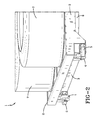
- the pallets 1 of this invention have a top plate 2, stringers 3, at least four vertically mounted support wheels 4, and at least four horizontally mounted guide wheels 5 as illustrated in Figures 1 and 2 .
- the wheels 4 of this invention are preferably high quality wheels, such as caster wheels, to ensure that the pallets will travel smoothly through the racks without sticking or jamming.
- the pallets 1 of this invention can optionally have a top plate 2 which includes at least one tapered or venturi shaped depression 6 which is adapted for transporting and storing green tires 7.
- the pallets 1 can also be designed to include other features which are adapted for transporting and storing a wide variety of manufactured products or component parts.
- the pallet in another embodiment, can be of a general purpose design which can transport or store a wide variety of different variegated manufactured products, component parts, or raw materials on the same pallet.
- the pallets 1 utilized in the practice of this invention can optionally be equipped with bumpers or cushioning devices to absorb impact energy so as to protect the pallets 1 and the system from damage which occurs as the pallets 1 move through the system and collide with each other.
- the pallet 1 depicted in Figure 1 includes four tapered or venturi shaped depressions 6 which are adapted for holding and transporting green tires 7. It is unique and beneficial to transport tires in groups of four to improve efficiency within the system. However, such pallets can be designed to transport any desired number of tires. For instance, a pallet which is utilized in transporting large truck tires may conveniently be adapted for holding only a single tire. Pallets 1 a can also be adapted for holding two tires, four tires, or some other multiple of two or three. For instance, the pallet 1 can be designed to hold virtually any desired number of small sized tires such as golf cart tires, ATV tires, motorcycle tires and the like. The inclusion of multiple tapered or venture shaped depressions can be cost effective by virtue of making more efficient use of the pallets and the system in general.
- the pallets 1 will include at least four vertically mounted support wheels 4 which are adapted for traveling on pallet support rails 8 within the pigeonholes 10 of the rack system 11.
- the pallets 1 will also include horizontally mounted guide wheels 5 which are adapted for alignment with pallet alignment rails 12 which are situated within the pigeonholes 10 of the rack system 11. It is convenient to utilize a single angle iron structural shape which serves as both the support rail 8 and as the alignment rail 12, as shown in Figure 3 . These angle iron shaped pieces are typically affixed at the two bottom corners of each pigeonhole 10.
- the pallet rack system will typically have pigeonholes which run at an angle of inclination from front to back which is within the range of about 1° to about 8°.
- the angle of inclination can be within the range of about 1° to about 4° and will frequently be within the range of about 1.5° to about 3°.
- this angle is measured from the front to the back of the rack with the back of the rack being higher than the front of the rack.
- this angle of inclination is measured from the pallet removal end of the rack to the pallet insertion end of the rack with the pallet insertion end of the rack being higher than the pallet removal end of the rack.
- the racks 13 utilized in conjunction with the pallets 1 of this invention will include an array of pigeonholes 10 which are deep enough to hold a plurality of such pallets. These pigeonholes 10 will normally be in an array where they are at least several rows deep (stacked on top of each other) and many rows wide. In some cases, it is desirable to include pigeonholes of differing heights to maximize storage capacity. For instance, empty pallets can be stored in pigeonholes which are of a minimum height. On the other hand, passenger and light truck tires will require a pigeonhole of greater height with the pigeonhole required to hold the largest tires having an even greater height. Thus, the rack systems utilized in accordance with this invention can optionally have pigeonholes which are of more than one height.
- FIG. 4 depicts one embodiment of the subject invention wherein the pallets are used in a pallet flow rack system.
- the pallet flow rack system includes at least one pallet flow rack 18 having a plurality of pigeonholes and a plurality of pallets.
- Incoming goods 21 are loaded onto pallets at a pallet loading point 19. These loaded pallets are then moved into pigeonholes within the flow rack system.
- the pigeonholes have a pallet insertion end 14 and a pallet removal end 15, this allows loaded pallets 17 in the system to move in the direction that corresponds to the arrangement of the pigeonholes.
- Outgoing goods 22 are unloaded from the pallets at a pallet unloading point 20.
- Empty pallets 16 generally move in a direction that is opposite to the direction that the loaded pallets 17 move. In any case, the empty pallets move from the pallet unloading point 20 to the pallet loading point 19. This system efficiently makes empty pallets 16 available to become loaded at the moment that they are needed to transport goods.
- the pallet insertion end 14 of the pigeonholes is at a lower level than the pallet removal end 15 of the pigeonholes. This arrangement allows the force of gravity to facilitate pallet movement through the rack system.
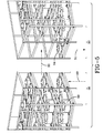
- FIGS 5 and 6 depict another embodiment of the subject invention wherein the pallets are used in a pallet push back system.
- the pallet push back rack system shown includes two pallet racks, shown as a first pallet rack 23 (as illustrated in Figure 6 ), 28 (as illustrated in Figure 5 ) and a second pallet rack 27, 32.
- loaded pallets 33 and empty pallets 34 may be added and/or removed from either the first pallet rack 23, 28 or the second pallet rack 27, 32 in three simple steps.
- the pallet push back rack system can include a single pallet rack or multiples thereof, positioned adjacently or in tandem to one another.
- loaded pallets can be added to the pallet push back system for storage of inventory.
- step one 24 a loaded pallet is added to a first pigeon hole in a first pallet rack 23, 28.
- step two 25 30 a pallet transport cart within the gantry is free to move to a second pigeonhole which contains an empty pallet, and remove the empty pallet from that second pigeonhole.
- This movement can be from a pigeonhole within the first pallet rack 23, 28 to a pigeonhole within a second pallet rack 27, 32, or the movement can be from a pigeonhole within the first pallet rack 23, 28 to a second pigeonhole within the first pallet rack 23, 28.
- step three 26 31 a pallet transport cart moves the empty pallet through the gantry, and exits from the pallet rack system.
- step one 24, 29 a pallet transport cart moves an empty pallet to a pigeonhole having the capacity to hold at least one additional pallet, and the empty pallet is inserted into that pigeonhole.
- step two 25 the pallet transport cart within the gantry moves to a pigeonhole which contains a loaded pallet, and it removes the loaded pallet from that pigeonhole.
- step three 26, 31 a pallet transport cart moves the loaded pallet through the gantry, and exits the pallet rack system. After exiting the system, the loaded pallet is unloaded and the resulting empty pallet may be returned to the rack system.
- the pallet push back rack system as depicted in Figure 5 and Figure 6 includes a first rack 23, 28 and a second rack 27, 32 with the first rack 23, 28 being opposite to the second rack 27, 32, wherein a gantry is between the first rack 23, 28 and the second rack 27, 32, and wherein said pallets are stored on and retrieved from the first rack 23, 28 and the second rack 27, 32 from a single point of entry.
- This pallet push back rack system can include loaded pallets and empty pallets wherein essentially all empty pallets are stored in pigeonholes as a function of the system.
- One of the benefits of this system is that it simplifies and improves system flow and the handling of both empty and loaded pallets by minimizing unnecessary movement within the system.
- the storage of manufactured goods, in process inventory, and raw materials is more efficiently balanced using this system. This system effectively minimizes pallet build-up outside of the system and simultaneously provides quick access to loaded or empty pallets when they are needed.
- the pallet push back rack system is particularly useful in conjunction with the claimed invention to tire manufacturers, because it enables manufacturers to balance the flow of tires in the building phases and curing phases of the tire manufacturing process. This is because there is frequently an imbalance between the number of tires being built and the curing capacity, which is dependent upon numerous variables including: types of tires, tire sizes, curing temperatures, and curing times required. Any manufacturer producing goods wherein there is imbalance in in-process inventory anywhere within the manufacturing process can benefit from using such a pallet push back rack system, including the three point movement previously described. This system eliminates waiting time associated with mechanically handling goods and with multiple gantry systems, because it allows for a single gantry to more efficiently facilitate the flow of pallets between racks.
- a single gantry in this system can deposit a first pallet into a first pigeonhole, remove a second pallet from a second pigeonhole, and exit the rack area from the same space in which it entered the rack area.
- vertically mounted wheels may have a rotation axis which is substantially parallel to the top plate of the pallet.
- Horizontally mounted wheels may have a rotation axis which is substantially perpendicular to the top plate of the pallet.
Landscapes
- Engineering & Computer Science (AREA)
- Mechanical Engineering (AREA)
- Warehouses Or Storage Devices (AREA)
Applications Claiming Priority (1)
| Application Number | Priority Date | Filing Date | Title |
|---|---|---|---|
| US201462074456P | 2014-11-03 | 2014-11-03 |
Publications (1)
| Publication Number | Publication Date |
|---|---|
| EP3015403A1 true EP3015403A1 (fr) | 2016-05-04 |
Family
ID=54366055
Family Applications (1)
| Application Number | Title | Priority Date | Filing Date |
|---|---|---|---|
| EP15192660.7A Withdrawn EP3015403A1 (fr) | 2014-11-03 | 2015-11-02 | Palette pour le stockage et le transport d'articles |
Country Status (2)
| Country | Link |
|---|---|
| US (1) | US10106293B2 (fr) |
| EP (1) | EP3015403A1 (fr) |
Cited By (1)
| Publication number | Priority date | Publication date | Assignee | Title |
|---|---|---|---|---|
| DE102022202201A1 (de) | 2022-03-03 | 2023-09-07 | Continental Reifen Deutschland Gmbh | Lagersystem zur schonenden Verbringung und Lagerung von Fahrzeugreifenrohlingen |
Families Citing this family (11)
| Publication number | Priority date | Publication date | Assignee | Title |
|---|---|---|---|---|
| EP2947030A1 (fr) * | 2014-05-23 | 2015-11-25 | Pesmel Group Oy | Transtockeur comprenant deux plateformes de chargement et méthode utilisant un tel transélévateur dans un entrepôt |
| JP6507517B2 (ja) * | 2014-08-06 | 2019-05-08 | キョーラク株式会社 | タイヤホイール用搬送材 |
| US11084622B2 (en) * | 2014-12-09 | 2021-08-10 | Swisslog Logistics, Inc. | Structure for automated pallet storage and retrieval |
| USD766539S1 (en) * | 2014-12-24 | 2016-09-13 | Korea Container Pool Co., Ltd. | Transporting tray for motor vehicle wheels |
| US9457703B2 (en) * | 2015-02-17 | 2016-10-04 | William N. Moore | Mobile tire storage |
| CA2947988A1 (fr) * | 2015-11-09 | 2017-05-09 | Rehrig Pacific Company | Palette |
| FI126980B (en) * | 2016-10-05 | 2017-09-15 | Hartwall K Oy Ab | Logistics system, adapter pallet and load carrier |
| US11478079B2 (en) | 2019-11-13 | 2022-10-25 | Pipp Mobile Storage Systems, Inc. | Mobile storage system with elevated platform |
| CA203647S (en) | 2021-05-21 | 2023-02-24 | Canadian Tire Corporation Ltd | Tire storage apparatus |
| US12037029B2 (en) * | 2022-01-20 | 2024-07-16 | Tsg Canada Holdings Inc. | Railcar systems and cargo transportation methods |
| TWM637508U (zh) * | 2022-09-19 | 2023-02-11 | 台朔重工股份有限公司 | 用於輪圈之智慧物流系統 |
Citations (12)
| Publication number | Priority date | Publication date | Assignee | Title |
|---|---|---|---|---|
| GB1109015A (en) * | 1966-03-04 | 1968-04-10 | Truform Plastics Ltd | Improvements in or relating to containers |
| JPS6160506A (ja) * | 1984-08-31 | 1986-03-28 | Kawatetsu Intaareiku Kk | 立体自動倉庫システム |
| US4582188A (en) * | 1985-02-22 | 1986-04-15 | Variable Control Systems, Inc. | Speed controller for pallets |
| US4988251A (en) * | 1987-10-21 | 1991-01-29 | Interlake, Inc. | Multiple load storage rack structure |
| EP0425908A1 (fr) * | 1989-11-02 | 1991-05-08 | Uniroyal Goodrich Licensing Services, Inc. | Récipient pour un pneu radial non-vulcanisé |
| JPH04140131A (ja) * | 1990-10-02 | 1992-05-14 | Mitsubishi Heavy Ind Ltd | 生タイヤの搬送方法 |
| US5642976A (en) * | 1994-10-21 | 1997-07-01 | Konstant Products, Inc. | Unloading device |
| US5840237A (en) * | 1995-10-02 | 1998-11-24 | Sumitomo Rubber Industries, Ltd. | Pallet for raw cover tire and manufacturing method of tire using the same |
| EP1223003A1 (fr) * | 2001-01-15 | 2002-07-17 | Prodel Holding | Installation pour la circulation de palettes porte-pièces et palette pour cette installation |
| EP1970319A1 (fr) * | 2007-03-15 | 2008-09-17 | Robert Bosch GmbH | Agencement en forme de palette pour l'emballage de marchandises |
| JP2013086901A (ja) * | 2011-10-17 | 2013-05-13 | Daifuku Co Ltd | 可動荷台付き棚 |
| JP2014156306A (ja) * | 2013-02-15 | 2014-08-28 | Sanshin Kinzoku Kogyo Kk | 傾斜式流動ラック |
Family Cites Families (29)
| Publication number | Priority date | Publication date | Assignee | Title |
|---|---|---|---|---|
| US2950014A (en) | 1957-03-07 | 1960-08-23 | Alvey Ferguson Co | Conveyor-type article storage rack having lift-out rail sections |
| US3399784A (en) | 1966-08-01 | 1968-09-03 | Ardco Inc | Shelving units with rolling shelves |
| US4197047A (en) | 1975-11-28 | 1980-04-08 | Weelpal Ag | Shelf storage system |
| GB1558141A (en) | 1977-01-07 | 1979-12-19 | Lansing Bagnall Ltd | Storage racks for warehouses and the like |
| DE2829325C3 (de) | 1978-07-04 | 1981-10-22 | Döring, Erich, 9442 Berneck, Sankt Gallen | Hochregal für Platten |
| US4462500A (en) | 1982-05-19 | 1984-07-31 | Speedrack, Inc. | Multiple location storage bays |
| US4613270A (en) | 1983-11-17 | 1986-09-23 | Speedrack, Inc. | Storage rack having bays with multiple rails and interlocking trolleys |
| US4687404A (en) | 1985-02-22 | 1987-08-18 | Seiz Corporation | Load transfer apparatus for push-in flow racks |
| US4715765A (en) | 1986-04-10 | 1987-12-29 | Charles Agnoff | Gravity flow storage system |
| US4773546A (en) | 1987-05-21 | 1988-09-27 | Konstant Products, Inc. | Pallet rack |
| US4936738A (en) | 1988-04-26 | 1990-06-26 | Food Plant Engineering, Inc. | Alternating push back selective rack storage system |
| US4915240A (en) | 1989-02-16 | 1990-04-10 | Konstant Products, Inc. | Multiple pallet rack |
| US4949852A (en) | 1989-09-13 | 1990-08-21 | Frazier Industrial Company | Storage rack systems |
| US4982851A (en) | 1990-02-07 | 1991-01-08 | Konstant Anthony N | Supported pallet rack |
| US5141118A (en) | 1990-11-20 | 1992-08-25 | Gay Kenneth F | Multiple carriage based rack assembly |
| US5080241A (en) | 1991-02-08 | 1992-01-14 | Konstant Anthony N | Rolling rack for skids and the like |
| US5184738A (en) | 1991-06-07 | 1993-02-09 | Frazier Industrial Company | Storage rack systems |
| US5178288A (en) | 1991-11-18 | 1993-01-12 | Interroll Canada Limited | Push back pallet rack |
| US5170896A (en) | 1992-03-16 | 1992-12-15 | Konstant Products, Inc. | Pallet return pallet rack system |
| US5285909A (en) | 1993-02-04 | 1994-02-15 | Slater Robert C | Pallet storage rack |
| US5328038A (en) | 1993-02-10 | 1994-07-12 | Frazier Industrial Company | Storage rack systems |
| CA2098433C (fr) | 1993-06-15 | 1995-04-04 | Todd Scott | Systeme d'entreposage de palettes |
| US5482422A (en) | 1994-08-15 | 1996-01-09 | Hammond; Theodore A. | Push back storage rack |
| US6112915A (en) | 1995-02-14 | 2000-09-05 | Lewis; Lyman F. | Push-back storage rack |
| US6158943A (en) | 1999-06-28 | 2000-12-12 | Sullivan; Chad D. | Pushback storage system |
| CA2336502A1 (fr) | 2000-07-12 | 2002-01-12 | Ridg-U-Rak, Inc. | Systeme de stockage vers l'arriere |
| KR100548018B1 (ko) * | 2003-06-19 | 2006-01-31 | 한국타이어 주식회사 | 그린타이어 적재용 팔레트의 자동보관 입출고 시스템 |
| US8594835B2 (en) * | 2009-04-10 | 2013-11-26 | Symbotic, LLC | Control system for storage and retrieval systems |
| US8739985B2 (en) | 2010-12-15 | 2014-06-03 | J. C. M. Industries, Inc. | Push-back cart storage system with a top cart rolling on top of push-back rails |
-
2015
- 2015-10-27 US US14/924,152 patent/US10106293B2/en not_active Expired - Fee Related
- 2015-11-02 EP EP15192660.7A patent/EP3015403A1/fr not_active Withdrawn
Patent Citations (12)
| Publication number | Priority date | Publication date | Assignee | Title |
|---|---|---|---|---|
| GB1109015A (en) * | 1966-03-04 | 1968-04-10 | Truform Plastics Ltd | Improvements in or relating to containers |
| JPS6160506A (ja) * | 1984-08-31 | 1986-03-28 | Kawatetsu Intaareiku Kk | 立体自動倉庫システム |
| US4582188A (en) * | 1985-02-22 | 1986-04-15 | Variable Control Systems, Inc. | Speed controller for pallets |
| US4988251A (en) * | 1987-10-21 | 1991-01-29 | Interlake, Inc. | Multiple load storage rack structure |
| EP0425908A1 (fr) * | 1989-11-02 | 1991-05-08 | Uniroyal Goodrich Licensing Services, Inc. | Récipient pour un pneu radial non-vulcanisé |
| JPH04140131A (ja) * | 1990-10-02 | 1992-05-14 | Mitsubishi Heavy Ind Ltd | 生タイヤの搬送方法 |
| US5642976A (en) * | 1994-10-21 | 1997-07-01 | Konstant Products, Inc. | Unloading device |
| US5840237A (en) * | 1995-10-02 | 1998-11-24 | Sumitomo Rubber Industries, Ltd. | Pallet for raw cover tire and manufacturing method of tire using the same |
| EP1223003A1 (fr) * | 2001-01-15 | 2002-07-17 | Prodel Holding | Installation pour la circulation de palettes porte-pièces et palette pour cette installation |
| EP1970319A1 (fr) * | 2007-03-15 | 2008-09-17 | Robert Bosch GmbH | Agencement en forme de palette pour l'emballage de marchandises |
| JP2013086901A (ja) * | 2011-10-17 | 2013-05-13 | Daifuku Co Ltd | 可動荷台付き棚 |
| JP2014156306A (ja) * | 2013-02-15 | 2014-08-28 | Sanshin Kinzoku Kogyo Kk | 傾斜式流動ラック |
Cited By (1)
| Publication number | Priority date | Publication date | Assignee | Title |
|---|---|---|---|---|
| DE102022202201A1 (de) | 2022-03-03 | 2023-09-07 | Continental Reifen Deutschland Gmbh | Lagersystem zur schonenden Verbringung und Lagerung von Fahrzeugreifenrohlingen |
Also Published As
| Publication number | Publication date |
|---|---|
| US20160122078A1 (en) | 2016-05-05 |
| US10106293B2 (en) | 2018-10-23 |
Similar Documents
| Publication | Publication Date | Title |
|---|---|---|
| US10106293B2 (en) | Pallet for the storage and transportation of articles | |
| US20250066126A1 (en) | Transfer device and order fulfillment facility for picking articles | |
| US11208264B2 (en) | System for storing and transporting objects stored in racks of a warehouse | |
| US6325586B1 (en) | Automated storage and retrieval system | |
| CN107428469B (zh) | 物品处理系统与方法 | |
| US20120141236A1 (en) | Method and storage system for storing and order-picking articles | |
| TWI499547B (zh) | Automatic Warehouse and Automatic Warehouse Storage Method | |
| KR102934053B1 (ko) | 저장 장치의 운용 방법 | |
| CN106458445A (zh) | 仓库和用于仓库的寻址车 | |
| CN112384453A (zh) | 拣选货品的系统和方法 | |
| MXPA99009849A (es) | Tarima para almacenar articulos con ruedas. | |
| EP3129306B1 (fr) | Agencement de stockage de marchandises à plusieurs étages | |
| US12479658B2 (en) | Goods-storage and order-fulfillment system | |
| WO2024197071A1 (fr) | Chariot utilitaire à emboîtement empilable omnidirectionnel | |
| KR102895083B1 (ko) | 편하중 물품을 안정적으로 입출고할 수 있는 스마트 자동창고 | |
| JPS6134354Y2 (fr) | ||
| JPH0610210U (ja) | 物品保管棚のスライド式物品入出庫機構 | |
| CN217577417U (zh) | 用于汽车座椅骨架冲压铁片的自动化仓储物流配送系统 | |
| JPS6232165Y2 (fr) | ||
| EP3511267B1 (fr) | Systeme d'entrepot automatique pour panneaux | |
| NO348182B1 (en) | A vertically displaceable lifting frame for transporting a goods holder to/from a storage volume of an automated storage and retrieval system | |
| US20190382219A1 (en) | Device for storing and transporting large-volume foam blocks | |
| JPH08333006A (ja) | 自動倉庫設備 | |
| CN121269263A (zh) | 一种垛板进出库装置和垛板进出库方法 | |
| KR200218630Y1 (ko) | 핸드 캐리어용 사방인입 펠릿 |
Legal Events
| Date | Code | Title | Description |
|---|---|---|---|
| PUAI | Public reference made under article 153(3) epc to a published international application that has entered the european phase |
Free format text: ORIGINAL CODE: 0009012 |
|
| AK | Designated contracting states |
Kind code of ref document: A1 Designated state(s): AL AT BE BG CH CY CZ DE DK EE ES FI FR GB GR HR HU IE IS IT LI LT LU LV MC MK MT NL NO PL PT RO RS SE SI SK SM TR |
|
| AX | Request for extension of the european patent |
Extension state: BA ME |
|
| 17P | Request for examination filed |
Effective date: 20161104 |
|
| RBV | Designated contracting states (corrected) |
Designated state(s): AL AT BE BG CH CY CZ DE DK EE ES FI FR GB GR HR HU IE IS IT LI LT LU LV MC MK MT NL NO PL PT RO RS SE SI SK SM TR |
|
| 17Q | First examination report despatched |
Effective date: 20170420 |
|
| STAA | Information on the status of an ep patent application or granted ep patent |
Free format text: STATUS: THE APPLICATION HAS BEEN WITHDRAWN |
|
| 18W | Application withdrawn |
Effective date: 20171010 |