EP3018242A1 - Appareil de fabrication de fil - Google Patents
Appareil de fabrication de fil Download PDFInfo
- Publication number
- EP3018242A1 EP3018242A1 EP13888677.5A EP13888677A EP3018242A1 EP 3018242 A1 EP3018242 A1 EP 3018242A1 EP 13888677 A EP13888677 A EP 13888677A EP 3018242 A1 EP3018242 A1 EP 3018242A1
- Authority
- EP
- European Patent Office
- Prior art keywords
- carbon nanotube
- nozzle
- yarn
- yarn producing
- swirl flow
- Prior art date
- Legal status (The legal status is an assumption and is not a legal conclusion. Google has not performed a legal analysis and makes no representation as to the accuracy of the status listed.)
- Granted
Links
Images


Classifications
-
- D—TEXTILES; PAPER
- D01—NATURAL OR MAN-MADE THREADS OR FIBRES; SPINNING
- D01H—SPINNING OR TWISTING
- D01H1/00—Spinning or twisting machines in which the product is wound-up continuously
- D01H1/11—Spinning by false-twisting
- D01H1/115—Spinning by false-twisting using pneumatic means
-
- D—TEXTILES; PAPER
- D01—NATURAL OR MAN-MADE THREADS OR FIBRES; SPINNING
- D01G—PRELIMINARY TREATMENT OF FIBRES, e.g. FOR SPINNING
- D01G23/00—Feeding fibres to machines; Conveying fibres between machines
-
- D—TEXTILES; PAPER
- D01—NATURAL OR MAN-MADE THREADS OR FIBRES; SPINNING
- D01G—PRELIMINARY TREATMENT OF FIBRES, e.g. FOR SPINNING
- D01G5/00—Separating, e.g. sorting, fibres
-
- D—TEXTILES; PAPER
- D01—NATURAL OR MAN-MADE THREADS OR FIBRES; SPINNING
- D01H—SPINNING OR TWISTING
- D01H15/00—Piecing arrangements ; Automatic end-finding, e.g. by suction and reverse package rotation; Devices for temporarily storing yarn during piecing
- D01H15/002—Piecing arrangements ; Automatic end-finding, e.g. by suction and reverse package rotation; Devices for temporarily storing yarn during piecing for false-twisting spinning machines
-
- D—TEXTILES; PAPER
- D02—YARNS; MECHANICAL FINISHING OF YARNS OR ROPES; WARPING OR BEAMING
- D02G—CRIMPING OR CURLING FIBRES, FILAMENTS, THREADS, OR YARNS; YARNS OR THREADS
- D02G3/00—Yarns or threads, e.g. fancy yarns; Processes or apparatus for the production thereof, not otherwise provided for
- D02G3/02—Yarns or threads characterised by the material or by the materials from which they are made
- D02G3/16—Yarns or threads made from mineral substances
-
- D—TEXTILES; PAPER
- D10—INDEXING SCHEME ASSOCIATED WITH SUBLASSES OF SECTION D, RELATING TO TEXTILES
- D10B—INDEXING SCHEME ASSOCIATED WITH SUBLASSES OF SECTION D, RELATING TO TEXTILES
- D10B2101/00—Inorganic fibres
- D10B2101/10—Inorganic fibres based on non-oxides other than metals
- D10B2101/12—Carbon; Pitch
- D10B2101/122—Nanocarbons
Definitions
- the present invention relates to a yarn producing apparatus for producing carbon nanotube yarn.
- Patent Literature 1 A known example of conventional yarn producing apparatus for producing carbon nanotube yarn is disclosed, for example, in Patent Literature 1.
- nanotube fibers are drawn from a nanotube forest (carbon nanotube assembly) provided on a substrate and then false-twisted by a spinneret.
- Patent Literature 1 Japanese Unexamined Patent Application Publication (Translation of PCT Application) No. 2008-523254
- the fiber is introduced into the yarn producing unit through rollers.
- Fiber of carbon nanotubes has the property of easily aggregating and retains its shape once aggregated. For this reason, the carbon nanotube fibers are compressed and aggregated into the form of a strip when passing through the rollers, and retain the shape. In this case, the carbon nanotube fibers aggregated in the form of a strip are twisted in the yarn producing unit, as a result, low-density yarn including voids is produced.
- the yarn producing apparatus disclosed in Patent Literature 1 has a configuration effective in preventing low yarn density because the carbon nanotube fibers are introduced into the spinneret directly from the nanotube forest. It is, however, difficult to increase the speed of producing carbon nanotube yarn with the yarn producing apparatus in Patent Literature 1 because the carbon nanotube fibers are twisted by the spinneret.
- An object of the present invention is to provide a yarn producing apparatus capable of producing high-density carbon nanotube yarn at high speed.
- a yarn producing apparatus produces carbon nanotube yarn from carbon nanotube fibers while allowing the carbon nanotube fibers to run.
- the yarn producing apparatus includes a support configured to support a carbon nanotube assembly, a drawing unit configured to continuously draw the carbon nanotube fibers from the carbon nanotube assembly supported on the support and to allow the carbon nanotube fibers to run, and a yarn producing unit provided between the support and the drawing unit to directly take in the carbon nanotube fibers drawn by the drawing unit and twist the taken-in carbon nanotube fibers.
- the yarn producing unit false-twists the carbon nanotube fibers with a swirl flow of compressed air.
- the yarn producing unit directly takes in the carbon nanotube fibers drawn by the drawing unit and false-twists the taken-in carbon nanotube fibers. That is, the carbon nanotube fibers drawn from the carbon nanotube assembly are directly introduced into the yarn producing unit without passing through rollers or other parts.
- the yarn producing apparatus thus can produce high-density carbon nanotube yarn because the carbon nanotube fibers are twisted in a state of having a non-flat shape. In the yarn producing apparatus, the carbon nanotube fibers are twisted by a swirl flow of the compressed air. The yarn producing apparatus therefore can produce carbon nanotube yarn from the carbon nanotube fibers at high speed.
- the drawing unit may include a nip roller unit including a pair of rollers.
- a balloon is generated in the carbon nanotube fibers (twisted yarn) output from the yarn producing unit.
- the yarn producing apparatus therefore includes the nip roller unit.
- the nip roller unit stops the balloon (stops twisting) of yarn output from the yarn producing unit. In the yarn producing apparatus, therefore, the yarn can be stably wound.
- the distance between the carbon nanotube assembly supported on the support and the yarn producing unit may be smaller than the distance between the yarn producing unit and the nip roller unit.
- the distance between the carbon nanotube assembly and the yarn producing unit is shortened, whereby the twisting in the yarn producing unit effectively acts on the carbon nanotube fibers drawn from the carbon nanotube assembly.
- the yarn producing apparatus therefore can produce excellent carbon nanotube yarn.
- the yarn producing unit may include a nozzle body configured to allow the carbon nanotube fibers to pass through, a first nozzle provided in the nozzle body to generate a first swirl flow, with compressed air, in a direction orthogonal to a direction of the carbon nanotube fibers running, and a second nozzle provided in the nozzle body to generate a second swirl flow, with compressed air, in a direction orthogonal to the direction of the carbon nanotube fibers running and opposite to the direction of the first swirl flow.
- the first nozzle and the second nozzle may be provided at positions different in the direction of the carbon nanotube fibers running in the nozzle body.
- the first nozzle generates a first swirl flow
- the second nozzle generates a second swirl flow in a direction opposite to the direction of the first swirl flow.
- the carbon nanotube fibers can be stably false-twisted at high speed.
- the first nozzle may be provided on an upstream side from the second nozzle in the direction of the carbon nanotube fibers running.
- the pressure of the compressed air for forming the first swirl flow may be lower than the pressure of the compressed air for forming the second swirl flow.
- the pressure of the compressed air for forming the first swirl flow is reduced, that is, the pressure of the compressed air for forming the second swirl flow is increased, so that the carbon nanotube fibers can be false-twisted excellently.
- the first swirl flow generated in the first nozzle may mainly twine part of an outer surface of the carbon nanotube fibers
- the second swirl flow generated in the second nozzle may mainly false-twist the carbon nanotube fibers to aggregate the carbon nanotube fibers.
- the carbon nanotube fibers can be false-twisted excellently.
- the nozzle body may have an air escape portion between the first nozzle and the second nozzle. This configuration can eliminate or minimize the interference between the first swirl flow in the first nozzle and the second swirl flow in the second nozzle in the yarn producing apparatus. Disturbances in the swirl flow in each nozzle thus can be eliminated or minimized, leading to improvement in quality of carbon nanotube yarn.
- the air escape portion may be a notch cut in the nozzle body.
- the nozzle body excluding the notch can minimize or eliminate scattering of the carbon nanotube fibers.
- the present invention can produce high-density carbon nanotube yarn at high speed.
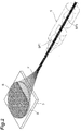
- FIG 1 is a diagram illustrating a yarn producing apparatus according to an embodiment.
- FIG 2 is a partial perspective view of the yarn producing apparatus shown in FIG 1 .
- a yarn producing apparatus 1 is an apparatus for producing carbon nanotube yarn (hereinafter referred to as "CNT yarn”) Y from carbon nanotube fibers (hereinafter referred to as "CNT fibers”) F while allowing the CNT fibers F to run.
- CNT yarn carbon nanotube yarn
- CNT fibers carbon nanotube fibers
- the yarn producing apparatus 1 includes a substrate support (support) 3, a yarn producing unit 5, and a drawing unit.
- the drawing unit includes nip rollers 7a, 7b, and a winding device 9.
- the substrate support 3, the yarn producing unit 5, the nip rollers 7a, 7b, and the winding device 9 are arranged in this order on a predetermined line.
- the CNT fibers F run from the substrate support 3 toward the winding device 9.
- the CNT fibers F are a set of a plurality of fibers of carbon nanotube.
- the CNT yarn Y consists of the false-twisted and aggregated CNT fibers F.
- the substrate support 3 supports a carbon nanotube-forming substrate (hereinafter referred to as "CNT forming substrate") S from which the CNT fibers F are drawn, in state of holding the CNT forming substrate S.
- the CNT forming substrate S is a carbon nanotube assembly called a carbon nanotube forest or a vertically aligned carbon nanotube structure, in which high-density and high-oriented carbon nanotubes (for example, single-wall carbon nanotubes, double-wall carbon nanotubes, or multi-wall carbon nanotubes) are formed on a substrate B by chemical vapor deposition or any other process.
- the substrate B include a plastic substrate, a glass substrate, a silicon substrate, and a metal substrate.
- a tool called microdrill can be used to draw the CNT fibers F from the CNT forming substrate S.
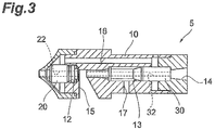
- FIG 3 is a diagram illustrating the yarn producing unit.
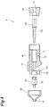
- FIG 4 is an exploded view of the yarn producing unit shown in FIG 3 .
- a nozzle body 10 is illustrated in cross section.
- the yarn producing unit 5 includes a nozzle body 10, a first nozzle 20, and a second nozzle 30.
- the first nozzle 20 and the second nozzle 30 are provided in the nozzle body 10.
- the nozzle body 10, the first nozzle 20, and the second nozzle 30 form a unit.
- the nozzle body 10 is a housing that allows the CNT fibers F to pass through and holds the first nozzle 20 and the second nozzle 30 therein.
- the nozzle body 10 is formed of, for example, brass or any other material.
- the nozzle body 10 has an inlet 11 that allows the CNT fibers F to pass through and through which the CNT fibers F are introduced into the nozzle body 10, a first compartment 12 that accommodates the first nozzle 20, a second compartment 13 that accommodates the second nozzle 30, and an outlet 14 that allows the CNT fibers F to pass through and through which the CNT fibers F are output from the nozzle body 10.
- the first compartment 12 and the second compartment 13 are arranged in the direction of the CNT fibers F running.
- the first compartment 12 is provided on one end in the direction of the CNT fibers F running (the position on the upstream side in the direction of the CNT fibers F running, in the yarn producing unit 5 arranged as shown in FIG 1 ).
- the second compartment 13 is provided on the other end in the direction of the CNT fibers F running (the position on the downstream side from the first compartment 12, in the yarn producing unit 5 arranged as shown in FIG 1 ).
- An air escape portion 15 is arranged between the first compartment 12 and the second compartment 13.
- the air escape portion 15 lets out a first swirl flow SF 1 generated in the first nozzle 20.
- the air escape portion 15 is a notch cut in the nozzle body 10.
- the air escape portion 15 is provided so as to include a path through which the CNT fibers F run.
- the path of the CNT fibers F between the first compartment 12 and the second compartment 13 is in communication with the air escape portion 15 and is partially covered with the nozzle body 10.
- the nozzle body 10 has a first channel 16 and a second channel 17.
- the first channel 16 is a channel in communication with the first compartment 12 to supply the compressed air to the first nozzle 20.
- the second channel 17 is a channel in communication with the second compartment 13 to supply the compressed air to the second nozzle 30.
- the nozzle body 10 is configured with a plurality of (here, three) parts in the present embodiment, the nozzle body 10 may be formed in one piece.
- the first nozzle 20 generates a first swirl flow SF 1 to form a balloon in the CNT fibers F and twist the CNT fibers F.
- the first nozzle 20 is formed of, for example, ceramics.
- the first nozzle 20 is arranged in the first compartment 12 of the nozzle body 10.
- the first nozzle 20 has a tubular portion 22 that allows the CNT fibers F to pass through and defines a space in which the first swirl flow SF1 is generated.
- the tubular portion 22 is provided in the direction of the CNT fibers F running.
- the first nozzle 20 is supplied with the compressed air from a not-shown air supply source through the first channel 16 in the nozzle body 10, as shown in FIG 5 .
- a first swirl flow SF1 is generated in the direction orthogonal to the direction of the CNT fibers F running, for example, counterclockwise around the running direction.
- the first swirl flow SF1 is generated along the inner wall of the tubular portion 22.
- the first swirl flow SF1 mainly twines the outside fibers (part of the outer layer) of the CNT fibers F, around the inside fibers.
- the pressure (static pressure) of the compressed air for forming the first swirl flow SF1 is, for example, about 0.25 MPa.
- the second nozzle 30 generates a second swirl flow SF2 to form a balloon in the CNT fibers F and twist the CNT fibers F.
- the second nozzle 30 is formed of, for example, ceramics.
- the second nozzle 30 is arranged in the second compartment 13 of the nozzle body 10.
- the second nozzle 30 has a tubular portion 32 that allows the CNT fibers F to pass through and defines a space in which the second swirl flow SF2 is generated.
- the tubular portion 32 is provided in the direction of the CNT fibers F running.
- the second nozzle 30 is supplied with the compressed air from a not-shown air supply source through the second channel 17 in the nozzle body 10, as shown in FIG 5 .
- a second swirl flow SF2 is generated in the direction orthogonal to the direction of the CNT fibers F running and opposite to the direction of the first swirl flow SF1, for example, clockwise around the running direction. That is, the direction of the second swirl flow SF2 is opposite to the direction of the first swirl flow SF1.
- the second swirl flow SF2 is generated along the inner wall of the tubular portion 32.
- the second swirl flow SF2 mainly twists the core (the inside fibers) of the CNT fibers F in the direction opposite to the direction of the first swirl flow SF 1.
- the pressure (static pressure) of the compressed air for forming the second swirl flow SF2 is, for example, about 0.4 to 0.6 MPa. That is, the pressure of the compressed air for forming the second swirl flow SF2 is higher than the pressure of the compressed air for forming the first swirl flow SF1. In other words, the pressure of the compressed air for forming the first swirl flow SF1 is lower than the pressure of the compressed air for forming the second swirl flow SF2.
- the nip rollers 7a, 7b convey the aggregated CNT yarn Y false-twisted by the yarn producing unit 5.
- a pair of nip rollers 7a, 7b is arranged at a position at which the CNT yarn Y is sandwiched.
- the nip rollers 7a, 7b stop the twisting (balloon) of the CNT fibers F that propagates from the yarn producing unit 5.
- the CNT fibers F false-twisted by the yarn producing unit 5 pass through the nip rollers 7a, 7b to be further aggregated, yielding the CNT yarn Y, which is the final product.
- the distance L1 between the CNT forming substrate S and the yarn producing unit 5 is smaller than the distance L2 between the yarn producing unit 5 and the nip rollers 7a, 7b (L1 ⁇ L2). That is, the yarn producing unit 5 is arranged at a position near the CNT forming substrate S.
- the winding device 9 winds, around a bobbin, the CNT yarn Y that has been false-twisted by the yarn producing unit 5 and passed through the nip rollers 7a, 7b.
- the winding device 9 draws the CNT fibers F from the CNT forming substrate S and allows the CNT fibers F to run.
- the winding device 9 draws the CNT fibers F from the CNT forming substrate S supported on the substrate support 3.
- the drawn CNT fibers F are directly introduced into the yarn producing unit 5.
- the CNT fibers F introduced into the yarn producing unit 5 start being twisted by the second swirl flow SF2 in the second nozzle 30 of the yarn producing unit 5.
- the aggregated CNT fibers F twisted by the second swirl flow SF2 are untwisted by the first swirl flow SF1 in the first nozzle 20.
- Part (outer surface) of the CNT fibers F not aggregated by the second swirl flow SF2 is twined around the aggregated surface by the first swirl flow SF1 in the first nozzle 20.
- the yarn producing unit 5 thus aggregates the CNT fibers F.
- the CNT fibers F twisted by the yarn producing unit 5 are formed into the CNT yarn Y, which in turn is wound around a bobbin by the winding device 9.
- the yarn producing apparatus 1 produces the CNT yarn Y, for example, at a rate of a few tens of meters per minute.
- the yarn producing unit 5 directly takes in the CNT fibers F drawn by the winding device 9 and twists the taken-in CNT fibers F. That is, the CNT fibers F drawn from the CNT forming substrate S are directly introduced into the yarn producing unit 5 without passing through rollers or other parts.
- the yarn producing apparatus 1 therefore produces high-density CNT yarn Y because the CNT fibers F in a state of having a non-flat shape (strip) (in a not-aggregated state) are twisted.
- the CNT fibers F are twisted by a swirl flow of the compressed air. The yarn producing apparatus 1 thus can produce the CNT yarn Y from the CNT fibers F at high speed.
- the nip rollers 7a, 7b are arranged between the yarn producing unit 5 and the winding device 9.
- the nip rollers 7a, 7b are arranged between the yarn producing unit 5 and the winding device 9.
- the nip rollers 7a, 7b can stop the balloon (stop twisting) of yarn output from the yarn producing unit 5.
- the CNT yarn Y can be stably wound.
- the distance between the CNT forming substrate S supported on the substrate support 3 and the yarn producing unit 5 is smaller than the distance between the yarn producing unit 5 and the nip rollers 7a, 7b.
- the distance between the CNT forming substrate S and the yarn producing unit 5 is shortened, whereby the twisting in the yarn producing unit 5 effectively acts on the CNT fibers F drawn from the CNT forming substrate S.
- the yarn producing apparatus 1 therefore can produce excellent CNT yarn Y.
- the first nozzle 20 generates a first swirl flow SF1
- the second nozzle 30 generates a second swirl flow SF2 in the direction opposite to the direction of the first swirl flow SF1.
- the CNT fibers F can be false-twisted at high speed.
- the first nozzle 20 and the second nozzle 30 are each provided in the nozzle body 10 to form a unit and are arranged at different positions in the direction of the CNT fibers F running. This configuration can facilitate passage of the CNT fibers F through the first nozzle 20 and the second nozzle 30 in the yarn producing apparatus 1.
- the first nozzle 20 is arranged on the upstream side from the second nozzle 30 in the direction of the CNT fibers F running.
- the pressure of the compressed air for forming the first swirl flow SF 1 is lower than the pressure of the compressed air for forming the second swirl flow SF2.
- the first swirl flow SF 1 generated in the first nozzle 20 mainly twines part of the outside of the CNT fibers F, whereas the second swirl flow SF2 generated in the second nozzle 30 mainly twists the CNT fibers F.
- the CNT fibers F can be false-twisted excellently, thereby being aggregated.
- the air escape portion 15 is provided between the first nozzle 20 and the second nozzle 30 in the nozzle body 10.
- the air escape portion 15 is a notch cut in the nozzle body 10. This configuration can eliminate or minimize the interference between the first swirl flow SF 1 in the first nozzle 20 and the second swirl flow SF2 in the second nozzle 30 in the yarn producing unit 5.
- disturbances in swirl flows SF1, SF2 in the nozzles 20, 30, respectively can be minimized or eliminated, leading to improvement in the quality of the CNT yarn Y.
- the nozzle body 10 excluding the air escape portion 15 can eliminate or minimize scattering of the CNT fibers F.
- a floating catalyst apparatus that continuously synthesizes carbon nanotubes to supply the CNT fibers F may be used as the supply source of the CNT fibers F.
- the distance L1 between the CNT forming substrate S and the yarn producing unit 5 is smaller than the distance L2 between the yarn producing unit 5 and the nip rollers 7a, 7b (L1 ⁇ L2).
- this configuration is given only for illustration, and the distance L1 between the CNT forming substrate S and the yarn producing unit 5 may be equal to the distance L2 between the yarn producing unit 5 and the nip rollers 7a, 7b.
- the distance L1 between the CNT forming substrate S and the yarn producing unit 5 may be greater than the distance L2 between the yarn producing unit 5 and the nip rollers 7a, 7b.
- the pressure of the compressed air for forming the first swirl flow SF 1 is set lower than the pressure of the compressed air for forming the second swirl flow SF2.
- the respective pressures of the compressed airs for forming the first swirl flow and for forming the second swirl flow SF2 may be equal.
- the pressure of the compressed air for forming the second swirl flow SF2 may be set lower than the pressure of the compressed air for forming the first swirl flow SF1.
- the configuration in which the first nozzle 20 and the second nozzle 30 are arranged in the nozzle body 10 has been described, by way of example.
- the first nozzle and the second nozzle may be spaces formed in the nozzle body 10. That is, the configuration equivalent to the first nozzle 20 and the second nozzle 30 may be integrally formed in the nozzle body 10.
- the present invention can provide a yarn producing apparatus capable of producing high-density carbon nanotube yarn at high speed.
Landscapes
- Engineering & Computer Science (AREA)
- Textile Engineering (AREA)
- Mechanical Engineering (AREA)
- Yarns And Mechanical Finishing Of Yarns Or Ropes (AREA)
- Physics & Mathematics (AREA)
- Thermal Sciences (AREA)
- Chemical & Material Sciences (AREA)
- Chemical Kinetics & Catalysis (AREA)
- General Chemical & Material Sciences (AREA)
Applications Claiming Priority (1)
| Application Number | Priority Date | Filing Date | Title |
|---|---|---|---|
| PCT/JP2013/068537 WO2015001669A1 (fr) | 2013-07-05 | 2013-07-05 | Appareil de fabrication de fil |
Publications (3)
| Publication Number | Publication Date |
|---|---|
| EP3018242A1 true EP3018242A1 (fr) | 2016-05-11 |
| EP3018242A4 EP3018242A4 (fr) | 2017-02-15 |
| EP3018242B1 EP3018242B1 (fr) | 2019-10-23 |
Family
ID=52143285
Family Applications (1)
| Application Number | Title | Priority Date | Filing Date |
|---|---|---|---|
| EP13888677.5A Active EP3018242B1 (fr) | 2013-07-05 | 2013-07-05 | Appareil de fabrication de fil |
Country Status (7)
| Country | Link |
|---|---|
| US (1) | US10443156B2 (fr) |
| EP (1) | EP3018242B1 (fr) |
| JP (1) | JP5971419B2 (fr) |
| KR (1) | KR20160022929A (fr) |
| CN (1) | CN105339535A (fr) |
| TW (1) | TWI645087B (fr) |
| WO (1) | WO2015001669A1 (fr) |
Families Citing this family (12)
| Publication number | Priority date | Publication date | Assignee | Title |
|---|---|---|---|---|
| KR101821162B1 (ko) * | 2013-07-05 | 2018-01-23 | 무라다기카이가부시끼가이샤 | 실 제조 장치 |
| WO2015011760A1 (fr) * | 2013-07-22 | 2015-01-29 | 村田機械株式会社 | Dispositif de fabrication de fil |
| US10472739B2 (en) * | 2013-07-22 | 2019-11-12 | Murata Machinery Ltd. | Yarn manufacturing device |
| US9945053B2 (en) * | 2013-07-22 | 2018-04-17 | Murata Machinery, Ltd. | Yarn manufacturing apparatus |
| JP5943149B2 (ja) * | 2013-07-22 | 2016-06-29 | 村田機械株式会社 | 糸製造装置 |
| TWI744279B (zh) * | 2016-01-29 | 2021-11-01 | 日商日立造船股份有限公司 | 奈米碳管紗線的製造方法 |
| CN106381592A (zh) * | 2016-09-07 | 2017-02-08 | 苏州捷迪纳米科技有限公司 | 碳纳米管扁丝及其制备方法和制备装置 |
| US10425993B2 (en) * | 2016-12-08 | 2019-09-24 | Goodrich Corporation | Carbon nanotube yarn heater |
| KR101987337B1 (ko) * | 2018-03-21 | 2019-06-10 | 주식회사 제이오 | 일정 방향성을 갖는 집속공정을 적용한 탄소나노튜브 섬유 및 그 제조 장치 |
| CN109537110B (zh) * | 2018-12-19 | 2021-03-12 | 苏州大学 | 一种碳纳米管纤维的制备方法 |
| WO2021106227A1 (fr) | 2019-11-29 | 2021-06-03 | 村田機械株式会社 | Capteur de pression de contact, article en tricot équipé de celui-ci, et procédé de fabrication d'un capteur de pression de contact |
| WO2022251485A1 (fr) * | 2021-05-26 | 2022-12-01 | Direct Air Capture, Llc | Appareil, système et procédé de fabrication d'une fibre et de textiles en nanomatériau de carbone à partir de dioxyde de carbone et de matériaux, et matériaux et produits associés |
Family Cites Families (12)
| Publication number | Priority date | Publication date | Assignee | Title |
|---|---|---|---|---|
| GB1164612A (en) | 1966-01-31 | 1969-09-17 | Scragg & Sons | Drive for Spindles of Textile Machines |
| JPS6134234A (ja) * | 1984-07-26 | 1986-02-18 | Murata Mach Ltd | 空気式紡績装置 |
| US8926933B2 (en) | 2004-11-09 | 2015-01-06 | The Board Of Regents Of The University Of Texas System | Fabrication of twisted and non-twisted nanofiber yarns |
| CN100500556C (zh) * | 2005-12-16 | 2009-06-17 | 清华大学 | 碳纳米管丝及其制作方法 |
| WO2008022129A2 (fr) * | 2006-08-14 | 2008-02-21 | Cnt Technologies, Inc. | Système et procédés pour centrifuger des nanotubes de carbone en fil, et fil obtenu par ce système et ces procédés |
| WO2009045487A1 (fr) * | 2007-10-02 | 2009-04-09 | Los Alamos National Security, Llc | Fibre de nanotube de carbone filée à partir de ruban mouillé |
| JP5229732B2 (ja) * | 2008-11-11 | 2013-07-03 | 地方独立行政法人大阪府立産業技術総合研究所 | 微細炭素繊維撚糸の製造装置及び製造方法 |
| JP5699387B2 (ja) * | 2010-03-29 | 2015-04-08 | 地方独立行政法人大阪府立産業技術総合研究所 | カーボンナノチューブ撚糸およびその製造方法 |
| CN101967699B (zh) * | 2010-10-13 | 2012-08-08 | 中国科学院苏州纳米技术与纳米仿生研究所 | 高性能碳纳米管纤维的制备方法 |
| CN102953171A (zh) * | 2011-08-30 | 2013-03-06 | 苏州捷迪纳米科技有限公司 | 碳纳米管纺纱机及采用该碳纳米管纺纱机制备碳纳米管纱线的方法 |
| KR101821162B1 (ko) * | 2013-07-05 | 2018-01-23 | 무라다기카이가부시끼가이샤 | 실 제조 장치 |
| US9945053B2 (en) * | 2013-07-22 | 2018-04-17 | Murata Machinery, Ltd. | Yarn manufacturing apparatus |
-
2013
- 2013-07-05 KR KR1020167002223A patent/KR20160022929A/ko not_active Ceased
- 2013-07-05 CN CN201380077811.5A patent/CN105339535A/zh active Pending
- 2013-07-05 JP JP2015524995A patent/JP5971419B2/ja active Active
- 2013-07-05 US US14/902,277 patent/US10443156B2/en active Active
- 2013-07-05 EP EP13888677.5A patent/EP3018242B1/fr active Active
- 2013-07-05 WO PCT/JP2013/068537 patent/WO2015001669A1/fr not_active Ceased
-
2014
- 2014-07-02 TW TW103122840A patent/TWI645087B/zh not_active IP Right Cessation
Non-Patent Citations (1)
| Title |
|---|
| See references of WO2015001669A1 * |
Also Published As
| Publication number | Publication date |
|---|---|
| TW201506214A (zh) | 2015-02-16 |
| CN105339535A (zh) | 2016-02-17 |
| US20160201229A1 (en) | 2016-07-14 |
| EP3018242A4 (fr) | 2017-02-15 |
| US10443156B2 (en) | 2019-10-15 |
| EP3018242B1 (fr) | 2019-10-23 |
| JP5971419B2 (ja) | 2016-08-17 |
| WO2015001669A1 (fr) | 2015-01-08 |
| KR20160022929A (ko) | 2016-03-02 |
| TWI645087B (zh) | 2018-12-21 |
| JPWO2015001669A1 (ja) | 2017-02-23 |
Similar Documents
| Publication | Publication Date | Title |
|---|---|---|
| EP3018242B1 (fr) | Appareil de fabrication de fil | |
| US9945053B2 (en) | Yarn manufacturing apparatus | |
| EP3018241B1 (fr) | Appareil de fabrication de fil | |
| CN105378165B (zh) | 纱线制造装置 | |
| CN108486714A (zh) | 喷气涡流混纺纱的加工装置和方法 | |
| EP3156526B1 (fr) | Tige de guidage creuse, dispositif de filières à air et machinerie textile | |
| CN107974743B (zh) | 一种可生产非弹性包覆纱的空气包覆纱机 | |
| JP6689259B2 (ja) | 空気紡績機用の紡績ノズルおよび相応の紡績ノズルを備えた空気紡績機 | |
| US20130269309A1 (en) | Machine and method for producing wool yarn | |
| CN202482539U (zh) | 包芯纱用的不锈钢丝切入式喂送装置 | |
| TW202229673A (zh) | 用於紡紗機的多功能噴嘴 | |
| CN103290539A (zh) | 一种赛络纺超柔软纺纱装置 | |
| CN103225144A (zh) | 一种四罗拉细纱机 | |
| CN203284526U (zh) | 一种预加捻细纱机 | |
| CN103014940B (zh) | 纺纱机 | |
| CN102560769A (zh) | 包芯纱用的不锈钢丝切入式喂送装置 | |
| CN103225142A (zh) | 一种预加捻细纱机 |
Legal Events
| Date | Code | Title | Description |
|---|---|---|---|
| PUAI | Public reference made under article 153(3) epc to a published international application that has entered the european phase |
Free format text: ORIGINAL CODE: 0009012 |
|
| 17P | Request for examination filed |
Effective date: 20151229 |
|
| AK | Designated contracting states |
Kind code of ref document: A1 Designated state(s): AL AT BE BG CH CY CZ DE DK EE ES FI FR GB GR HR HU IE IS IT LI LT LU LV MC MK MT NL NO PL PT RO RS SE SI SK SM TR |
|
| AX | Request for extension of the european patent |
Extension state: BA ME |
|
| DAX | Request for extension of the european patent (deleted) | ||
| A4 | Supplementary search report drawn up and despatched |
Effective date: 20170117 |
|
| RIC1 | Information provided on ipc code assigned before grant |
Ipc: D01H 1/115 20060101ALI20170111BHEP Ipc: D01F 9/127 20060101ALI20170111BHEP Ipc: D02G 3/16 20060101AFI20170111BHEP |
|
| STAA | Information on the status of an ep patent application or granted ep patent |
Free format text: STATUS: EXAMINATION IS IN PROGRESS |
|
| 17Q | First examination report despatched |
Effective date: 20180207 |
|
| GRAJ | Information related to disapproval of communication of intention to grant by the applicant or resumption of examination proceedings by the epo deleted |
Free format text: ORIGINAL CODE: EPIDOSDIGR1 |
|
| GRAP | Despatch of communication of intention to grant a patent |
Free format text: ORIGINAL CODE: EPIDOSNIGR1 |
|
| GRAP | Despatch of communication of intention to grant a patent |
Free format text: ORIGINAL CODE: EPIDOSNIGR1 |
|
| STAA | Information on the status of an ep patent application or granted ep patent |
Free format text: STATUS: GRANT OF PATENT IS INTENDED |
|
| INTG | Intention to grant announced |
Effective date: 20190516 |
|
| RIN1 | Information on inventor provided before grant (corrected) |
Inventor name: YANO, FUMIAKI |
|
| INTG | Intention to grant announced |
Effective date: 20190522 |
|
| GRAS | Grant fee paid |
Free format text: ORIGINAL CODE: EPIDOSNIGR3 |
|
| GRAA | (expected) grant |
Free format text: ORIGINAL CODE: 0009210 |
|
| STAA | Information on the status of an ep patent application or granted ep patent |
Free format text: STATUS: THE PATENT HAS BEEN GRANTED |
|
| AK | Designated contracting states |
Kind code of ref document: B1 Designated state(s): AL AT BE BG CH CY CZ DE DK EE ES FI FR GB GR HR HU IE IS IT LI LT LU LV MC MK MT NL NO PL PT RO RS SE SI SK SM TR |
|
| REG | Reference to a national code |
Ref country code: GB Ref legal event code: FG4D |
|
| REG | Reference to a national code |
Ref country code: CH Ref legal event code: EP |
|
| REG | Reference to a national code |
Ref country code: IE Ref legal event code: FG4D |
|
| REG | Reference to a national code |
Ref country code: DE Ref legal event code: R096 Ref document number: 602013062147 Country of ref document: DE |
|
| REG | Reference to a national code |
Ref country code: AT Ref legal event code: REF Ref document number: 1193721 Country of ref document: AT Kind code of ref document: T Effective date: 20191115 |
|
| REG | Reference to a national code |
Ref country code: NL Ref legal event code: MP Effective date: 20191023 |
|
| REG | Reference to a national code |
Ref country code: LT Ref legal event code: MG4D |
|
| PG25 | Lapsed in a contracting state [announced via postgrant information from national office to epo] |
Ref country code: PT Free format text: LAPSE BECAUSE OF FAILURE TO SUBMIT A TRANSLATION OF THE DESCRIPTION OR TO PAY THE FEE WITHIN THE PRESCRIBED TIME-LIMIT Effective date: 20200224 Ref country code: SE Free format text: LAPSE BECAUSE OF FAILURE TO SUBMIT A TRANSLATION OF THE DESCRIPTION OR TO PAY THE FEE WITHIN THE PRESCRIBED TIME-LIMIT Effective date: 20191023 Ref country code: LV Free format text: LAPSE BECAUSE OF FAILURE TO SUBMIT A TRANSLATION OF THE DESCRIPTION OR TO PAY THE FEE WITHIN THE PRESCRIBED TIME-LIMIT Effective date: 20191023 Ref country code: NO Free format text: LAPSE BECAUSE OF FAILURE TO SUBMIT A TRANSLATION OF THE DESCRIPTION OR TO PAY THE FEE WITHIN THE PRESCRIBED TIME-LIMIT Effective date: 20200123 Ref country code: LT Free format text: LAPSE BECAUSE OF FAILURE TO SUBMIT A TRANSLATION OF THE DESCRIPTION OR TO PAY THE FEE WITHIN THE PRESCRIBED TIME-LIMIT Effective date: 20191023 Ref country code: PL Free format text: LAPSE BECAUSE OF FAILURE TO SUBMIT A TRANSLATION OF THE DESCRIPTION OR TO PAY THE FEE WITHIN THE PRESCRIBED TIME-LIMIT Effective date: 20191023 Ref country code: GR Free format text: LAPSE BECAUSE OF FAILURE TO SUBMIT A TRANSLATION OF THE DESCRIPTION OR TO PAY THE FEE WITHIN THE PRESCRIBED TIME-LIMIT Effective date: 20200124 Ref country code: NL Free format text: LAPSE BECAUSE OF FAILURE TO SUBMIT A TRANSLATION OF THE DESCRIPTION OR TO PAY THE FEE WITHIN THE PRESCRIBED TIME-LIMIT Effective date: 20191023 Ref country code: FI Free format text: LAPSE BECAUSE OF FAILURE TO SUBMIT A TRANSLATION OF THE DESCRIPTION OR TO PAY THE FEE WITHIN THE PRESCRIBED TIME-LIMIT Effective date: 20191023 Ref country code: BG Free format text: LAPSE BECAUSE OF FAILURE TO SUBMIT A TRANSLATION OF THE DESCRIPTION OR TO PAY THE FEE WITHIN THE PRESCRIBED TIME-LIMIT Effective date: 20200123 |
|
| PG25 | Lapsed in a contracting state [announced via postgrant information from national office to epo] |
Ref country code: HR Free format text: LAPSE BECAUSE OF FAILURE TO SUBMIT A TRANSLATION OF THE DESCRIPTION OR TO PAY THE FEE WITHIN THE PRESCRIBED TIME-LIMIT Effective date: 20191023 Ref country code: RS Free format text: LAPSE BECAUSE OF FAILURE TO SUBMIT A TRANSLATION OF THE DESCRIPTION OR TO PAY THE FEE WITHIN THE PRESCRIBED TIME-LIMIT Effective date: 20191023 Ref country code: IS Free format text: LAPSE BECAUSE OF FAILURE TO SUBMIT A TRANSLATION OF THE DESCRIPTION OR TO PAY THE FEE WITHIN THE PRESCRIBED TIME-LIMIT Effective date: 20200224 |
|
| PG25 | Lapsed in a contracting state [announced via postgrant information from national office to epo] |
Ref country code: AL Free format text: LAPSE BECAUSE OF FAILURE TO SUBMIT A TRANSLATION OF THE DESCRIPTION OR TO PAY THE FEE WITHIN THE PRESCRIBED TIME-LIMIT Effective date: 20191023 |
|
| REG | Reference to a national code |
Ref country code: DE Ref legal event code: R097 Ref document number: 602013062147 Country of ref document: DE |
|
| PG2D | Information on lapse in contracting state deleted |
Ref country code: IS |
|
| PG25 | Lapsed in a contracting state [announced via postgrant information from national office to epo] |
Ref country code: EE Free format text: LAPSE BECAUSE OF FAILURE TO SUBMIT A TRANSLATION OF THE DESCRIPTION OR TO PAY THE FEE WITHIN THE PRESCRIBED TIME-LIMIT Effective date: 20191023 Ref country code: DK Free format text: LAPSE BECAUSE OF FAILURE TO SUBMIT A TRANSLATION OF THE DESCRIPTION OR TO PAY THE FEE WITHIN THE PRESCRIBED TIME-LIMIT Effective date: 20191023 Ref country code: CZ Free format text: LAPSE BECAUSE OF FAILURE TO SUBMIT A TRANSLATION OF THE DESCRIPTION OR TO PAY THE FEE WITHIN THE PRESCRIBED TIME-LIMIT Effective date: 20191023 Ref country code: RO Free format text: LAPSE BECAUSE OF FAILURE TO SUBMIT A TRANSLATION OF THE DESCRIPTION OR TO PAY THE FEE WITHIN THE PRESCRIBED TIME-LIMIT Effective date: 20191023 Ref country code: ES Free format text: LAPSE BECAUSE OF FAILURE TO SUBMIT A TRANSLATION OF THE DESCRIPTION OR TO PAY THE FEE WITHIN THE PRESCRIBED TIME-LIMIT Effective date: 20191023 Ref country code: IS Free format text: LAPSE BECAUSE OF FAILURE TO SUBMIT A TRANSLATION OF THE DESCRIPTION OR TO PAY THE FEE WITHIN THE PRESCRIBED TIME-LIMIT Effective date: 20200223 |
|
| REG | Reference to a national code |
Ref country code: AT Ref legal event code: MK05 Ref document number: 1193721 Country of ref document: AT Kind code of ref document: T Effective date: 20191023 |
|
| PLBE | No opposition filed within time limit |
Free format text: ORIGINAL CODE: 0009261 |
|
| STAA | Information on the status of an ep patent application or granted ep patent |
Free format text: STATUS: NO OPPOSITION FILED WITHIN TIME LIMIT |
|
| PG25 | Lapsed in a contracting state [announced via postgrant information from national office to epo] |
Ref country code: SM Free format text: LAPSE BECAUSE OF FAILURE TO SUBMIT A TRANSLATION OF THE DESCRIPTION OR TO PAY THE FEE WITHIN THE PRESCRIBED TIME-LIMIT Effective date: 20191023 Ref country code: IT Free format text: LAPSE BECAUSE OF FAILURE TO SUBMIT A TRANSLATION OF THE DESCRIPTION OR TO PAY THE FEE WITHIN THE PRESCRIBED TIME-LIMIT Effective date: 20191023 Ref country code: SK Free format text: LAPSE BECAUSE OF FAILURE TO SUBMIT A TRANSLATION OF THE DESCRIPTION OR TO PAY THE FEE WITHIN THE PRESCRIBED TIME-LIMIT Effective date: 20191023 |
|
| 26N | No opposition filed |
Effective date: 20200724 |
|
| PG25 | Lapsed in a contracting state [announced via postgrant information from national office to epo] |
Ref country code: AT Free format text: LAPSE BECAUSE OF FAILURE TO SUBMIT A TRANSLATION OF THE DESCRIPTION OR TO PAY THE FEE WITHIN THE PRESCRIBED TIME-LIMIT Effective date: 20191023 Ref country code: SI Free format text: LAPSE BECAUSE OF FAILURE TO SUBMIT A TRANSLATION OF THE DESCRIPTION OR TO PAY THE FEE WITHIN THE PRESCRIBED TIME-LIMIT Effective date: 20191023 |
|
| PG25 | Lapsed in a contracting state [announced via postgrant information from national office to epo] |
Ref country code: MC Free format text: LAPSE BECAUSE OF FAILURE TO SUBMIT A TRANSLATION OF THE DESCRIPTION OR TO PAY THE FEE WITHIN THE PRESCRIBED TIME-LIMIT Effective date: 20191023 |
|
| REG | Reference to a national code |
Ref country code: CH Ref legal event code: PL |
|
| REG | Reference to a national code |
Ref country code: BE Ref legal event code: MM Effective date: 20200731 |
|
| PG25 | Lapsed in a contracting state [announced via postgrant information from national office to epo] |
Ref country code: CH Free format text: LAPSE BECAUSE OF NON-PAYMENT OF DUE FEES Effective date: 20200731 Ref country code: IE Free format text: LAPSE BECAUSE OF NON-PAYMENT OF DUE FEES Effective date: 20200705 Ref country code: LI Free format text: LAPSE BECAUSE OF NON-PAYMENT OF DUE FEES Effective date: 20200731 Ref country code: LU Free format text: LAPSE BECAUSE OF NON-PAYMENT OF DUE FEES Effective date: 20200705 Ref country code: FR Free format text: LAPSE BECAUSE OF NON-PAYMENT OF DUE FEES Effective date: 20200731 |
|
| PG25 | Lapsed in a contracting state [announced via postgrant information from national office to epo] |
Ref country code: BE Free format text: LAPSE BECAUSE OF NON-PAYMENT OF DUE FEES Effective date: 20200731 |
|
| PG25 | Lapsed in a contracting state [announced via postgrant information from national office to epo] |
Ref country code: TR Free format text: LAPSE BECAUSE OF FAILURE TO SUBMIT A TRANSLATION OF THE DESCRIPTION OR TO PAY THE FEE WITHIN THE PRESCRIBED TIME-LIMIT Effective date: 20191023 Ref country code: MT Free format text: LAPSE BECAUSE OF FAILURE TO SUBMIT A TRANSLATION OF THE DESCRIPTION OR TO PAY THE FEE WITHIN THE PRESCRIBED TIME-LIMIT Effective date: 20191023 Ref country code: CY Free format text: LAPSE BECAUSE OF FAILURE TO SUBMIT A TRANSLATION OF THE DESCRIPTION OR TO PAY THE FEE WITHIN THE PRESCRIBED TIME-LIMIT Effective date: 20191023 |
|
| PG25 | Lapsed in a contracting state [announced via postgrant information from national office to epo] |
Ref country code: MK Free format text: LAPSE BECAUSE OF FAILURE TO SUBMIT A TRANSLATION OF THE DESCRIPTION OR TO PAY THE FEE WITHIN THE PRESCRIBED TIME-LIMIT Effective date: 20191023 |
|
| PGFP | Annual fee paid to national office [announced via postgrant information from national office to epo] |
Ref country code: GB Payment date: 20240620 Year of fee payment: 12 |
|
| PGFP | Annual fee paid to national office [announced via postgrant information from national office to epo] |
Ref country code: DE Payment date: 20240619 Year of fee payment: 12 |
|
| REG | Reference to a national code |
Ref country code: DE Ref legal event code: R119 Ref document number: 602013062147 Country of ref document: DE |
|
| GBPC | Gb: european patent ceased through non-payment of renewal fee |
Effective date: 20250705 |
|
| PG25 | Lapsed in a contracting state [announced via postgrant information from national office to epo] |
Ref country code: GB Free format text: LAPSE BECAUSE OF NON-PAYMENT OF DUE FEES Effective date: 20250705 |
|
| PG25 | Lapsed in a contracting state [announced via postgrant information from national office to epo] |
Ref country code: DE Free format text: LAPSE BECAUSE OF NON-PAYMENT OF DUE FEES Effective date: 20260203 |