EP3018428B1 - Champ de commande pour un appareil de chauffage - Google Patents
Champ de commande pour un appareil de chauffage Download PDFInfo
- Publication number
- EP3018428B1 EP3018428B1 EP15183861.2A EP15183861A EP3018428B1 EP 3018428 B1 EP3018428 B1 EP 3018428B1 EP 15183861 A EP15183861 A EP 15183861A EP 3018428 B1 EP3018428 B1 EP 3018428B1
- Authority
- EP
- European Patent Office
- Prior art keywords
- operator control
- heating
- control device
- control panel
- flap
- Prior art date
- Legal status (The legal status is an assumption and is not a legal conclusion. Google has not performed a legal analysis and makes no representation as to the accuracy of the status listed.)
- Active
Links
Images





Classifications
-
- F—MECHANICAL ENGINEERING; LIGHTING; HEATING; WEAPONS; BLASTING
- F24—HEATING; RANGES; VENTILATING
- F24H—FLUID HEATERS, e.g. WATER OR AIR HEATERS, HAVING HEAT-GENERATING MEANS, e.g. HEAT PUMPS, IN GENERAL
- F24H9/00—Details
- F24H9/20—Arrangement or mounting of control or safety devices
- F24H9/25—Arrangement or mounting of control or safety devices of remote control devices or control-panels
-
- F—MECHANICAL ENGINEERING; LIGHTING; HEATING; WEAPONS; BLASTING
- F24—HEATING; RANGES; VENTILATING
- F24H—FLUID HEATERS, e.g. WATER OR AIR HEATERS, HAVING HEAT-GENERATING MEANS, e.g. HEAT PUMPS, IN GENERAL
- F24H15/00—Control of fluid heaters
- F24H15/40—Control of fluid heaters characterised by the type of controllers
- F24H15/414—Control of fluid heaters characterised by the type of controllers using electronic processing, e.g. computer-based
- F24H15/45—Control of fluid heaters characterised by the type of controllers using electronic processing, e.g. computer-based remotely accessible
- F24H15/464—Control of fluid heaters characterised by the type of controllers using electronic processing, e.g. computer-based remotely accessible using local wireless communication
Definitions
- the invention relates to a device for controlling and/or regulating a heating or domestic appliance in a heating or domestic system, comprising an operating device and a control panel.
- the heating or domestic appliance has a housing with a flap, wherein the flap accommodates at least parts of a control for the heating or domestic appliance and makes them accessible from the outside.
- the invention further relates to a heating or domestic appliance in a heating or domestic system with such a device.
- the EP 1 978 426 A1 discloses an electrical household appliance having a control panel with a first and a second user interface.
- Control units for heating devices are also generally known.
- the DE 10 2004 025 927 A1 a household appliance, in particular a water heater, the housing of which has a flap which is designed as a control panel.
- Such control devices usually contain all control and regulation logic for the heating system, which makes the operation of these devices complicated.
- the heating or domestic appliance has a housing with a flap, wherein the flap accommodates at least parts of a control for the heating or domestic appliance and makes them accessible from the outside.
- the operating device and the control panel are separated from one another by the flap, wherein the operating device and the control panel are connected or connectable to one another.
- a heating or household appliance includes, for example, a gas water heater for heating heating and/or domestic water or other devices used in the household.
- connection between the control panel and the control device is understood to be a direct or indirect connection.
- a direct connection the control panel and the control panel are connected directly, for example via a cable.
- an indirect connection the control panel and the control device are connected to each other via another part, for example a device such as a control unit for the heating or household appliance, or a component, or they are indirectly connected to each other as part of a system, for example a bus system.
- a control panel is arranged on the outside of the flap and a control device is arranged on the inside of the flap.
- the control device When the flap is closed, the control device can be covered by the flap and the control panel can be visible and/or operated from the outside.
- the control device When the flap is open, the control device can be visible and/or operated from the outside.
- the control panel can be used to operate the heater and/or to make settings for heating operation, while the control device remains protected by the flap. This increases operating comfort.
- the control panel can be designed to be particularly simple and the range of controls compared to the control device can be focused on the most important and most frequently used properties, making operation even easier and more convenient.
- the flap to the control device only needs to be opened if more extensive settings are necessary.
- control device is switched off or in power-saving mode when the flap is closed.
- the flap has an outer front and an inner front, with the control panel being attached or attachable to the outer front and the control device to the inner front.
- the control device and the control panel can be attached to the flap together, so that the device can be designed in one piece, for example, which reduces costs but also increases ease of use. This means that all parts required to control and/or regulate the heating or household appliance are quickly and easily accessible.
- control panel and the control device are directly or indirectly connected to one another and/or communicate with one another. Data entered into the control panel can then be forwarded to the control device, where it is processed. The control panel and the control device can then use the same communication channels to control and/or regulate the heating or household appliance, which simplifies the manufacture and installation of the device and thus reduces costs and effort.
- control device and/or the control panel is communicatively connected or connectable to a control and/or regulating unit of the heating or house system.
- control panel can send entered and/or incoming data and/or signals to the control device and/or to the control and/or regulation unit, where the data is then further processed.
- control panel can be switched off when the heating or household appliance is inactive or can be put into a power-saving mode. Even if the control panel is not operated, it can switch off or switch to a power-saving mode.
- the control panel can also be switched off after a preset time or put into a power-saving mode.
- the control panel can be switched off or put into a power-saving mode by the control device and/or the control and/or regulating unit. The same is possible for the control device.
- control panel and/or the control device can be connected to a bus system, in particular to a bus system of a room control device and/or the heating or household appliance.
- a bus system in particular to a bus system of a room control device and/or the heating or household appliance.
- Data for example temperature values or times or individual profiles for operating the heating or household system, can be sent directly from a room in the building via the control panel to the control device and/or the control and/or regulating unit of the heating or household appliance, so that the heating or household appliance can be operated remotely.
- a connection can also exist to another device, in particular a mobile device, which is located inside or outside the building.
- the input device is backlit in color, whereby it can change color when touched.
- the control panel can be designed as touch buttons and/or the control panel as a touchscreen that reacts to touch.
- a menu can be selected using at least one specific input device, with a number of input devices lighting up depending on the respective menu. Color can change when the menu is exited. This makes it possible for only those input devices to light up and/or be selectable that represent a function in the respective menu and/or for which it makes sense to be selectable.
- the inner front is provided with a connecting part for the control device. This enables the control device to be mounted on the flap particularly easily.
- a particularly simple and stable way of connecting the control device to the inside front of the flap is to clip the control device into the connecting part.
- the flap can then be opened together with the control device attached to the connecting part.
- FIG. 1 shows an embodiment of a device 10 according to the invention on a housing 12 of a wall-mounted heating device 14, with which a fluid, for example water, is heated.
- the housing 12 comprises a flap 16, which is attached to the lower part of the housing 12 and is open.
- the flap 16 has an outer front 18 and an inner front 20, with a connecting part 22 attached to the inner front 20.
- an operating device 24 is located on the inner front 20, which is connected to the connecting part 22 and has a display.
- the flap 16 can be arranged at any other location of the housing 12, for example at the top of the housing or in the middle, so that the flap 16 is easily accessible from the outside.
- the flap 16 When opened, the flap 16 forms an angle of between 70° and 180° to the lower edge of the housing 12. Alternatively, the angle can also be between 90° and 150°.
- the control unit 24 is connected via data and/or signal lines to a control and/or regulating unit 25 which is installed inside the heater 14 ( Figure 2 ).
- the cables run in the connecting part 22 and are not visible from the outside (and therefore not in the Figure 1 shown).
- the control device 24 is connected to a bus system 26 of the heating or household appliance 14.
- Data for controlling and/or regulating the heater 14 are entered into the control device 24, such as a temperature for the water, a pump output for circulating the water, a volume flow, individual profiles for controlling and/or regulating the heater 14.
- the control device 24 also receives data from the heater 14, such as the current actual temperature of the water, the pump output, the current volume flow, an operating status, etc.
- the display of the control device 24 can, for example, output text or show a status, for example whether there is an error and what type it is or whether maintenance is necessary.
- Signal devices can also be attached to the control device 24, such as LEDs that flash to indicate a status or a message or the like.
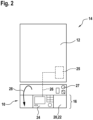
- Figure 2 shows the embodiment from Figure 1 in the front view, with the flap 16 open. Additional control elements 27 can be attached to the housing 12, which can be seen when the flap 16 is open.
- the arrow 28 indicates the direction of movement of the flap 16 when opening.
- the control device 24 is clearly visible and accessible in this position.
- FIG. 3 shows the same embodiment with the flap 16 closed. In this position, the operating device 24 is not visible from the outside. A control panel 30 can now be seen, which is attached to the outer front 18 of the flap 16. The operating device 24 and the control panel 30 are thus separated from one another by the flap 16.
- Figure 4 shows a rear view of the inner front 20 of the flap 16.
- the flap 16 with inner front 20 and outer front 18 is made of a glass material.
- the flap 16 is coated in color, for example by gluing on a colored film or a ceramic coating, whereby ceramic color is applied via screen printing and finally fired.
- the color of the area 32 influences the design and appearance of the device 10.
- a first cover 34 which is part of the connecting part 22, is attached to the inner front 20.
- the first cover 34 has a joint 36 for fastening the flap 16 to the housing 12.
- the first cover 34 is designed such that a second cover 37 can be mounted on the first cover 34.
- the second cover 37 can be clipped onto the first cover 34.
- the connecting part 22 therefore comprises the first and second covers 34, 37.
- Figure 1 shows a view of the inner front 20 of the flap 16, whereby the second cover 37 can also be seen.
- the operating device 24 is attached to the second cover 37.
- the operating device 24 and the second cover 37 are connected to one another by clipping.
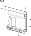
- Figure 5 shows a section of the rear view from Figure 4 along the axis V, allowing a view of the interior of the first cover 34.
- the circuit board 38 contains components for controlling and operating the control panel 30.
- Figure 6 shows an embodiment of the device 10 from the front. A front view of the flap 16 with a view of the elements located behind the outer front 18 is shown.
- the control panel 30 and the connecting part 22 behind it can be seen.
- the control panel 30 has a display 40 which is backlit, in particular backlit in color.
- the display 40 can be an LC display.
- the circuit board 38 has a U-shaped recess 48 into which the display 40 is inserted (see also Figure 9 ).
- the control panel 30 also has an area 42 for input means 44, the input means 44 being connected to the circuit board 38.
- the area 42 for the input means 44 is arranged around the display area 40. Behind the area 42 there is a layered light guide system 45 which is attached, for example glued, to the circuit board 38. This allows the input means 44 to be backlit in color.
- the input means 44 are designed as touch buttons which react to touch. When the input means 44 are touched, corresponding signals are sent to the light guide system 45 behind them so that the touched input means 44 lights up or changes color.
- the input means 44 are therefore such that they light up in one color and, as soon as they are touched, light up in a different color. Areas which show the position of the input means 44 can also be printed on the outer front 18 made of glass.
- the operator guidance is also implemented by a different colored backlighting of the input means 44, for example the touch buttons. Only active input means 44, i.e. touched or available for selection, are displayed. Input means 44 available for selection have a different color than selected input means 44. Furthermore, only those input means 44 that make sense and/or have a function, for example in a selected menu, can be recognized and selected. The number of available input means 44 then depends on the selected menu. If an input means 44 is selected, for example by touch, the color of the backlighting changes. An input means 44 can also represent a menu, so that a specific menu can be selected via it. The color of the input means 44 changes when the menu is selected and changes to a different color when the menu is exited. This enables intuitive operator guidance.
- Incoming signals are forwarded to the circuit board 38 via the input means 44, which makes it possible to control the control panel 30.
- control panel 30 switches off after a predeterminable time or switches to a power-saving mode.
- the backlighting of the display area 40, in particular the LC display, and/or the input means 44 switches off.
- the control device 24 can be switched off when the flap is closing or closed, or can be in a power-saving mode. As soon as the flap 16 is opened, the control device 24 switches on again so that it can be fully operated.
- switches or sensors can be provided that detect the movement of the flap 16 and send corresponding signals to the control device 24 and/or the control panel 30.
- a signal with the information that the control panel 30 is now being operated is sent to the control device 24, which then switches off or switches to power-saving mode.
- the control panel 30 is active or passive - that is, switched off or in a power-saving mode - and the control device 24 is passive or active.
- control device 24 and/or the control panel 30 can be switched off or placed in a power saving mode when the heater 14 is switched off or when the control device 24 and/or the control panel 30 are not operated.
- control panel 30 If the control panel 30 is in a power-saving mode, this is signaled to the user. For this purpose, there is an area on the display area 40 that is provided with a text, for example the text "OK", which lights up in power-saving mode. This also indicates that the control panel 30 is ready for use.
- the text for indicating the power saving mode can also be located at another location on the control panel 30, for example in the area 42.
- One of the input means 44 can be designed as an "OK" touch button, which lights up when the control panel 30 is in the power saving mode.
- the "OK" touch button changes color when it is touched.
- the control device 24 is also assigned a circuit board to which the control panel 30 is connected via a cable, in particular a 4-core cable.
- a cable, in particular an 8-core cable runs from the circuit board for the control device to the control and/or regulating unit 25 of the heater 14, whereby the control device 24 is connected to the control and/or regulating unit 25.
- Data entered into the control panel 30 is therefore sent to the control and/or regulating unit 25 via the circuit board for the control panel.
- the control device 24 knows data coming from the control panel 30, so that the control device 24 and the control panel 30 can communicate indirectly with each other.
- the connections, in particular the circuit board 46, can no longer be seen, as they are covered by the covers 34, 37.
- the cable or cables for connecting the various components, such as the control panel 30 and/or the control device 24, run inside the flap 16 within the connecting part 22 and cannot be seen from the outside, whether the flap 16 is open or closed.
- control panel 30 and the control device 24 are directly connected to one another. This is the case, for example, if the control panel 30 is part of the circuit board 38, so that the circuit board 38 and the control panel 30 form a unit.
- connections between the heater 14, the control and/or regulating unit 25, the operating device 24 and/or the control panel 30 are wireless connections, so that wireless communication is possible.
- the direct or indirect connection also exists when the flap 16 spatially separates the operating device 24 and the control panel 30 completely from one another.
- a wireless, indirect connection could also be made inductively between adjacent areas of the operating device 24 and the control panel 30 through a wall of the flap 16.
- Figure 7 shows a partial section in oblique view along line VII-VII from Figure 6 .
- the display 40 inserted into the recess 48, the area 42 for the input means 44 below the display 40 with the light guide system 45 and the first cover 34 can be seen.
- Figure 8 shows the same partial section Figure 7 along the line VII-VII Figure 6 , here in the front view of the cutting surface. The figure once again illustrates the arrangement of the individual parts of the device 10.
- the flap 16 has the outer front 18 made of glass, behind which the circuit board 38 with the light guide system 45 is arranged.
- the display 40 is inserted into the circuit board 38.
- the input means 44 are located on the circuit board 38. Behind this is the first cover 34, onto which the second cover 37 (not shown here) is attached.
- the operating device 24 is connected to the second cover 37 by clipping it in ( Figure 1 ).
- Figure 9 shows a front view of the circuit board 38.
- the U-shaped recess 48 and the area 42 with the input means 44, above which the light guide system 45 is arranged, can be seen.
- Figure 10 shows an embodiment of a device 10 according to the invention in a building 50, for example in a house or in an apartment.
- the building 50 has at least one room, in the embodiment a first floor 52 and a second floor 53 with two rooms.
- the device 10 is connected to the heating device 14 and the control and/or regulating unit 25 via data and/or signal lines or via the bus system 26.
- a room control unit 54 is located in a room on the second floor 53.
- the device 10 is connected to the room control unit 54 via the bus system 26, whereby the connection can also be a wireless connection. In this way, communication is possible between the room control unit 54 via the control panel 30 and/or the control unit 24 with the heating device 14.
Landscapes
- Engineering & Computer Science (AREA)
- Physics & Mathematics (AREA)
- Thermal Sciences (AREA)
- Chemical & Material Sciences (AREA)
- Combustion & Propulsion (AREA)
- Mechanical Engineering (AREA)
- General Engineering & Computer Science (AREA)
- Computer Networks & Wireless Communication (AREA)
- Computer Hardware Design (AREA)
- Electric Stoves And Ranges (AREA)
- Selective Calling Equipment (AREA)
- Central Heating Systems (AREA)
Claims (8)
- Appareil de chauffage ou appareil domestique (14), comprenant un dispositif (10) pour commander et/ou réguler l'appareil de chauffage ou l'appareil domestique (14) dans une installation de chauffage ou une installation domestique, dans lequel le dispositif (10) présente un appareil de commande (24) et un panneau de commande (30), l'appareil de chauffage ou l'appareil domestique (14) présentant un boîtier (12) pourvu d'une trappe (16), dans lequel la trappe (16) reçoit au moins certaines parties d'un dispositif de commande pour l'appareil de chauffage ou l'appareil domestique (14) et les rend accessibles vers l'extérieur, dans lequel l'appareil de commande (24) et le panneau de commande (30) sont séparés l'un de l'autre par la trappe (16), dans lequel l'appareil de commande (24) et le panneau de commande (30) sont ou peuvent être reliés ensemble, dans lequel un panneau de commande (30) est agencé sur l'extérieur de la trappe,
caractérisé en ce que
un appareil de commande (24) est agencé sur l'intérieur de la trappe (16), dans lequel- lorsque la trappe (16) est fermée, l'appareil de commande (24) est recouvert par la trappe (16), et le panneau de commande (30) est visible et/ou peut être commandé depuis l'extérieur, dans lequel lorsque la trappe (16) se ferme ou est fermée, l'appareil de commande (24) est mis hors tension ou se trouve dans un mode d'économie de courant,- lorsque la trappe (16) est ouverte, l'appareil de commande (24) est visible et/ou peut être commandé depuis l'extérieur. - Appareil de chauffage ou appareil domestique (14), comprenant un dispositif (10) selon la revendication 1, caractérisé en ce que le panneau de commande (30) et l'appareil de commande (24) communiquent ensemble.
- Appareil de chauffage ou appareil domestique (14), comprenant un dispositif (10) selon l'une quelconque des revendications 1 à 2, caractérisé en ce que l'appareil de commande (24) et/ou le panneau de commande sont ou peuvent être reliés en communication à une unité de commande et/ou de régulation (25) de l'installation de chauffage ou de l'installation domestique.
- Appareil de chauffage ou appareil domestique (14), comprenant un dispositif (10) selon l'une quelconque des revendications 1 à 3, caractérisé en ce que le panneau de commande (30) et/ou l'appareil de commande (24) peuvent être mis hors tension ou dans un mode d'économie de courant lorsque appareil de chauffage ou appareil domestique (14) est inactif et/ou en l'absence de toute commande et/ou après un délai prédéfinissable, en particulier par l'appareil de commande (24) et/ou par l'unité de commande et/ou de régulation (25).
- Appareil de chauffage ou appareil domestique (14), comprenant un dispositif (10) selon l'une quelconque des revendications 1 à 4, caractérisé en ce que l'appareil de commande (24) et/ou le panneau de commande (30) peuvent être reliés à un système de bus (26), en particulier à un système de bus (26) de l'appareil de chauffage ou de l'appareil domestique (14) et/ou d'un appareil de commande d'un local (54).
- Appareil de chauffage ou appareil domestique (14), comprenant un dispositif (10) selon l'une quelconque des revendications précédentes, caractérisé en ce que le panneau de commande (30) présente au moins un bouton tactile capacitif, et en ce que le panneau de commande (30) et/ou le bouton tactile capacitif sont rétroéclairés en couleur, la couleur changeant en cas de contact avec le bouton tactile capacitif et/ou le panneau de commande (30).
- Appareil de chauffage ou appareil domestique (14), comprenant un dispositif (10) selon la revendication 6, caractérisé en ce qu'un menu peut être choisi par au moins un moyen d'entrée (44) pouvant être désigné, dans lequel un nombre de moyens d'entrée (44) dépendant du menu en question s'illumine, et dans lequel la couleur change quand on quitte le menu.
- Appareil de chauffage ou appareil domestique (14) selon l'une quelconque des revendications précédentes, caractérisé en ce que la face avant intérieure (20) est pourvue d'une partie de jonction (22) pour l'appareil de commande (24), dans lequel l'appareil de commande (24) peut être relié à la partie de jonction (22) par enclenchement, et dans lequel la trappe (16) peut être ouverte conjointement avec l'appareil de commande (24) fixé à la partie de jonction (22).
Applications Claiming Priority (1)
| Application Number | Priority Date | Filing Date | Title |
|---|---|---|---|
| DE102014222758.5A DE102014222758A1 (de) | 2014-11-07 | 2014-11-07 | Bedienfeld für ein Heizgerät |
Publications (3)
| Publication Number | Publication Date |
|---|---|
| EP3018428A2 EP3018428A2 (fr) | 2016-05-11 |
| EP3018428A3 EP3018428A3 (fr) | 2016-07-13 |
| EP3018428B1 true EP3018428B1 (fr) | 2025-01-01 |
Family
ID=54064219
Family Applications (1)
| Application Number | Title | Priority Date | Filing Date |
|---|---|---|---|
| EP15183861.2A Active EP3018428B1 (fr) | 2014-11-07 | 2015-09-04 | Champ de commande pour un appareil de chauffage |
Country Status (2)
| Country | Link |
|---|---|
| EP (1) | EP3018428B1 (fr) |
| DE (1) | DE102014222758A1 (fr) |
Families Citing this family (7)
| Publication number | Priority date | Publication date | Assignee | Title |
|---|---|---|---|---|
| DE202017006749U1 (de) | 2017-11-30 | 2018-04-11 | Robert Bosch Gmbh | Heizvorrichtung mit einer Haltevorrichtung zur Aufnahme einer Steuereinheit |
| DE202017006746U1 (de) | 2017-11-30 | 2018-04-12 | Robert Bosch Gmbh | Heizvorrichtung mit einer Haltevorrichtung zur Aufnahme einer Steuereinheit |
| DE102017221534A1 (de) | 2017-11-30 | 2019-06-06 | Robert Bosch Gmbh | Haltevorrichtung für eine Heizvorrichtung, sowie Heizvorrichtung mit einer solchen Haltevorrichtung |
| DE202017006778U1 (de) | 2017-11-30 | 2018-05-17 | Robert Bosch Gmbh | Heizvorrichtung mit einer Haltevorrichtung zur Aufnahme einer Steuereinheit |
| DE102019203261A1 (de) * | 2019-03-08 | 2020-09-10 | Robert Bosch Gmbh | Heizvorrichtung |
| DE102022208775A1 (de) * | 2022-08-25 | 2024-03-07 | Robert Bosch Gesellschaft mit beschränkter Haftung | Heizgerät mit einem Gehäuse |
| DE102022209293A1 (de) * | 2022-09-07 | 2024-03-07 | Robert Bosch Gesellschaft mit beschränkter Haftung | Wärmepumpensystem-Steuerungskomponente |
Family Cites Families (8)
| Publication number | Priority date | Publication date | Assignee | Title |
|---|---|---|---|---|
| IT227142Y1 (it) * | 1992-10-29 | 1997-09-15 | Beretta Spa A | Dispositivo per la segnalazione visiva di anomalie di funzionamento in caldaie di piccola potenzialita' |
| DE19652130A1 (de) * | 1996-12-14 | 1998-06-18 | Stiebel Eltron Gmbh & Co Kg | Elektrischer Durchlauferhitzer |
| DE29716932U1 (de) * | 1997-09-20 | 1997-11-06 | Stiebel Eltron Gmbh & Co Kg, 37603 Holzminden | Gasheizgerät mit einem Bedien- und Anzeigemodul |
| NL1016284C2 (nl) * | 2000-09-27 | 2002-03-28 | Nefit Buderus B V | Verwarmingsinrichting met bedieningsmiddelen. |
| DE10236937A1 (de) * | 2002-08-12 | 2004-02-26 | BSH Bosch und Siemens Hausgeräte GmbH | Elektrisches Gerät |
| DE102004025927A1 (de) | 2004-05-27 | 2006-03-23 | BSH Bosch und Siemens Hausgeräte GmbH | Elektrisches Haushaltsgerät, insbesondere Warmwasserbereiter, insbesondere Durchlauferhitzer |
| ITRN20070020A1 (it) * | 2007-04-05 | 2008-10-06 | Indesit Co Spa | Elettrodomestico con doppia interfaccia e set di elettrodomestici dotati di un pannello di comando comune. |
| US8306669B1 (en) * | 2009-10-30 | 2012-11-06 | Tim Simon, Inc. | Method for operating a thermostatically controlled heater/cooler with fresh air intake |
-
2014
- 2014-11-07 DE DE102014222758.5A patent/DE102014222758A1/de not_active Ceased
-
2015
- 2015-09-04 EP EP15183861.2A patent/EP3018428B1/fr active Active
Also Published As
| Publication number | Publication date |
|---|---|
| DE102014222758A1 (de) | 2016-05-12 |
| EP3018428A2 (fr) | 2016-05-11 |
| EP3018428A3 (fr) | 2016-07-13 |
Similar Documents
| Publication | Publication Date | Title |
|---|---|---|
| EP3018428A2 (fr) | Champ de commande pour un appareil de chauffage | |
| DE102012210844A1 (de) | Kochanordnung, Verfahren zum Betreiben derselben, Induktions-Kochfeld und Dunstabzugshaube | |
| DE102009002774A1 (de) | Verfahren zum Betreiben eines Haushaltsgeräts, portable Bedieneinheit und Haushaltsgerät | |
| DE102014007177A1 (de) | System zum Steuern wenigstens eines Hausgerätes | |
| DE102019110052A1 (de) | Einrichtungselement mit Bedienteil | |
| EP2096368B1 (fr) | Dispositif et procédé d'allumage et d'arrêt d'un moteur à clapets à base d'un capteur de courant | |
| EP2922716B1 (fr) | Procédé d'affichage de l'état d'un dispositif de chauffage ou de climatisation d'un véhicule et dispositif de chauffage ou de climatisation pour un véhicule | |
| DE212017000161U1 (de) | System zur Automatisierung des Einschaltens, Einstellens und/oder Ausschaltens eines oder mehrerer Zubehörteile für Kochfelder | |
| CH705961B1 (de) | Verfahren zur Steuerung eines Raumlüftungssystems. | |
| EP3596368B1 (fr) | Unité d'ajustement pour un robinet sanitaire | |
| DE102019131487A1 (de) | Meldereinheit, Meldersystem sowie Verfahren zum Betrieb des Meldersystems | |
| DE102015117374A1 (de) | Steuereinrichtung für eine Absperrvorrichtung | |
| DE102016104321A1 (de) | Bedieneinrichtung für ein beabstandet zu der Bedieneinrichtung angeordnetes elektrisches Gerät einer Gebäudetechnikinstallation | |
| EP1894507B1 (fr) | Système aspirateur de poussières commandé par bus | |
| DE102009022898A1 (de) | Kochfeld | |
| DE102015006707A1 (de) | Fernbedienvorrichtung und fernbedienbares System zur Steuerung von Haus- oder Gebäudefunktionen | |
| DE102014210000A1 (de) | Vorortbedienung von Geräten eines Installationsbuses | |
| DE202013101825U1 (de) | Bediengerät zur Ansteuerung von Leuchten, Jalousien und/oder Klimageräten | |
| DE102012011775B4 (de) | Steuereinrichtung für einen Laborabzug und Laborabzug | |
| DE102015103822B3 (de) | Haushaltgerätesystem und Verfahren zum Betreiben eines Haushaltgerätesystems | |
| EP3513268A1 (fr) | Dispositif formant hotte aspirante pourvu de commande de lumière | |
| EP2469163B1 (fr) | Lampe à actionneurs | |
| DE19963293C1 (de) | Vorrichtung zur Wärmebehandlung von Nahrungsmitteln | |
| DE102023129696B4 (de) | Bedieneinrichtung für ein Elektrogerät und Elektrogerät | |
| DE102015013466B4 (de) | Bediengerät |
Legal Events
| Date | Code | Title | Description |
|---|---|---|---|
| PUAI | Public reference made under article 153(3) epc to a published international application that has entered the european phase |
Free format text: ORIGINAL CODE: 0009012 |
|
| AK | Designated contracting states |
Kind code of ref document: A2 Designated state(s): AL AT BE BG CH CY CZ DE DK EE ES FI FR GB GR HR HU IE IS IT LI LT LU LV MC MK MT NL NO PL PT RO RS SE SI SK SM TR |
|
| AX | Request for extension of the european patent |
Extension state: BA ME |
|
| PUAL | Search report despatched |
Free format text: ORIGINAL CODE: 0009013 |
|
| AK | Designated contracting states |
Kind code of ref document: A3 Designated state(s): AL AT BE BG CH CY CZ DE DK EE ES FI FR GB GR HR HU IE IS IT LI LT LU LV MC MK MT NL NO PL PT RO RS SE SI SK SM TR |
|
| AX | Request for extension of the european patent |
Extension state: BA ME |
|
| RIC1 | Information provided on ipc code assigned before grant |
Ipc: F24H 9/20 20060101AFI20160607BHEP |
|
| STAA | Information on the status of an ep patent application or granted ep patent |
Free format text: STATUS: REQUEST FOR EXAMINATION WAS MADE |
|
| 17P | Request for examination filed |
Effective date: 20170113 |
|
| RBV | Designated contracting states (corrected) |
Designated state(s): AL AT BE BG CH CY CZ DE DK EE ES FI FR GB GR HR HU IE IS IT LI LT LU LV MC MK MT NL NO PL PT RO RS SE SI SK SM TR |
|
| STAA | Information on the status of an ep patent application or granted ep patent |
Free format text: STATUS: EXAMINATION IS IN PROGRESS |
|
| 17Q | First examination report despatched |
Effective date: 20191217 |
|
| RAP1 | Party data changed (applicant data changed or rights of an application transferred) |
Owner name: ROBERT BOSCH GMBH |
|
| GRAP | Despatch of communication of intention to grant a patent |
Free format text: ORIGINAL CODE: EPIDOSNIGR1 |
|
| STAA | Information on the status of an ep patent application or granted ep patent |
Free format text: STATUS: GRANT OF PATENT IS INTENDED |
|
| INTG | Intention to grant announced |
Effective date: 20240722 |
|
| GRAS | Grant fee paid |
Free format text: ORIGINAL CODE: EPIDOSNIGR3 |
|
| GRAA | (expected) grant |
Free format text: ORIGINAL CODE: 0009210 |
|
| STAA | Information on the status of an ep patent application or granted ep patent |
Free format text: STATUS: THE PATENT HAS BEEN GRANTED |
|
| AK | Designated contracting states |
Kind code of ref document: B1 Designated state(s): AL AT BE BG CH CY CZ DE DK EE ES FI FR GB GR HR HU IE IS IT LI LT LU LV MC MK MT NL NO PL PT RO RS SE SI SK SM TR |
|
| REG | Reference to a national code |
Ref country code: GB Ref legal event code: FG4D Free format text: NOT ENGLISH |
|
| REG | Reference to a national code |
Ref country code: CH Ref legal event code: EP |
|
| REG | Reference to a national code |
Ref country code: DE Ref legal event code: R096 Ref document number: 502015017007 Country of ref document: DE |
|
| REG | Reference to a national code |
Ref country code: IE Ref legal event code: FG4D Free format text: LANGUAGE OF EP DOCUMENT: GERMAN |
|
| REG | Reference to a national code |
Ref country code: LT Ref legal event code: MG9D |
|
| REG | Reference to a national code |
Ref country code: NL Ref legal event code: MP Effective date: 20250101 |
|
| PG25 | Lapsed in a contracting state [announced via postgrant information from national office to epo] |
Ref country code: NL Free format text: LAPSE BECAUSE OF FAILURE TO SUBMIT A TRANSLATION OF THE DESCRIPTION OR TO PAY THE FEE WITHIN THE PRESCRIBED TIME-LIMIT Effective date: 20250101 |
|
| PG25 | Lapsed in a contracting state [announced via postgrant information from national office to epo] |
Ref country code: FI Free format text: LAPSE BECAUSE OF FAILURE TO SUBMIT A TRANSLATION OF THE DESCRIPTION OR TO PAY THE FEE WITHIN THE PRESCRIBED TIME-LIMIT Effective date: 20250101 |
|
| PG25 | Lapsed in a contracting state [announced via postgrant information from national office to epo] |
Ref country code: PL Free format text: LAPSE BECAUSE OF FAILURE TO SUBMIT A TRANSLATION OF THE DESCRIPTION OR TO PAY THE FEE WITHIN THE PRESCRIBED TIME-LIMIT Effective date: 20250101 |
|
| PG25 | Lapsed in a contracting state [announced via postgrant information from national office to epo] |
Ref country code: ES Free format text: LAPSE BECAUSE OF FAILURE TO SUBMIT A TRANSLATION OF THE DESCRIPTION OR TO PAY THE FEE WITHIN THE PRESCRIBED TIME-LIMIT Effective date: 20250101 |
|
| PG25 | Lapsed in a contracting state [announced via postgrant information from national office to epo] |
Ref country code: IS Free format text: LAPSE BECAUSE OF FAILURE TO SUBMIT A TRANSLATION OF THE DESCRIPTION OR TO PAY THE FEE WITHIN THE PRESCRIBED TIME-LIMIT Effective date: 20250501 Ref country code: NO Free format text: LAPSE BECAUSE OF FAILURE TO SUBMIT A TRANSLATION OF THE DESCRIPTION OR TO PAY THE FEE WITHIN THE PRESCRIBED TIME-LIMIT Effective date: 20250401 |
|
| PG25 | Lapsed in a contracting state [announced via postgrant information from national office to epo] |
Ref country code: HR Free format text: LAPSE BECAUSE OF FAILURE TO SUBMIT A TRANSLATION OF THE DESCRIPTION OR TO PAY THE FEE WITHIN THE PRESCRIBED TIME-LIMIT Effective date: 20250101 |
|
| PG25 | Lapsed in a contracting state [announced via postgrant information from national office to epo] |
Ref country code: LV Free format text: LAPSE BECAUSE OF FAILURE TO SUBMIT A TRANSLATION OF THE DESCRIPTION OR TO PAY THE FEE WITHIN THE PRESCRIBED TIME-LIMIT Effective date: 20250101 Ref country code: PT Free format text: LAPSE BECAUSE OF FAILURE TO SUBMIT A TRANSLATION OF THE DESCRIPTION OR TO PAY THE FEE WITHIN THE PRESCRIBED TIME-LIMIT Effective date: 20250502 |
|
| PG25 | Lapsed in a contracting state [announced via postgrant information from national office to epo] |
Ref country code: BG Free format text: LAPSE BECAUSE OF FAILURE TO SUBMIT A TRANSLATION OF THE DESCRIPTION OR TO PAY THE FEE WITHIN THE PRESCRIBED TIME-LIMIT Effective date: 20250101 Ref country code: GR Free format text: LAPSE BECAUSE OF FAILURE TO SUBMIT A TRANSLATION OF THE DESCRIPTION OR TO PAY THE FEE WITHIN THE PRESCRIBED TIME-LIMIT Effective date: 20250402 |
|
| PG25 | Lapsed in a contracting state [announced via postgrant information from national office to epo] |
Ref country code: CZ Free format text: LAPSE BECAUSE OF FAILURE TO SUBMIT A TRANSLATION OF THE DESCRIPTION OR TO PAY THE FEE WITHIN THE PRESCRIBED TIME-LIMIT Effective date: 20250101 |
|
| PG25 | Lapsed in a contracting state [announced via postgrant information from national office to epo] |
Ref country code: SE Free format text: LAPSE BECAUSE OF FAILURE TO SUBMIT A TRANSLATION OF THE DESCRIPTION OR TO PAY THE FEE WITHIN THE PRESCRIBED TIME-LIMIT Effective date: 20250101 |
|
| REG | Reference to a national code |
Ref country code: DE Ref legal event code: R097 Ref document number: 502015017007 Country of ref document: DE |
|
| PG25 | Lapsed in a contracting state [announced via postgrant information from national office to epo] |
Ref country code: SM Free format text: LAPSE BECAUSE OF FAILURE TO SUBMIT A TRANSLATION OF THE DESCRIPTION OR TO PAY THE FEE WITHIN THE PRESCRIBED TIME-LIMIT Effective date: 20250101 |
|
| PG25 | Lapsed in a contracting state [announced via postgrant information from national office to epo] |
Ref country code: DK Free format text: LAPSE BECAUSE OF FAILURE TO SUBMIT A TRANSLATION OF THE DESCRIPTION OR TO PAY THE FEE WITHIN THE PRESCRIBED TIME-LIMIT Effective date: 20250101 |
|
| PG25 | Lapsed in a contracting state [announced via postgrant information from national office to epo] |
Ref country code: IT Free format text: LAPSE BECAUSE OF FAILURE TO SUBMIT A TRANSLATION OF THE DESCRIPTION OR TO PAY THE FEE WITHIN THE PRESCRIBED TIME-LIMIT Effective date: 20250101 |
|
| PGFP | Annual fee paid to national office [announced via postgrant information from national office to epo] |
Ref country code: GB Payment date: 20250923 Year of fee payment: 11 |
|
| PGFP | Annual fee paid to national office [announced via postgrant information from national office to epo] |
Ref country code: FR Payment date: 20250925 Year of fee payment: 11 |
|
| PG25 | Lapsed in a contracting state [announced via postgrant information from national office to epo] |
Ref country code: EE Free format text: LAPSE BECAUSE OF FAILURE TO SUBMIT A TRANSLATION OF THE DESCRIPTION OR TO PAY THE FEE WITHIN THE PRESCRIBED TIME-LIMIT Effective date: 20250101 |
|
| PG25 | Lapsed in a contracting state [announced via postgrant information from national office to epo] |
Ref country code: RO Free format text: LAPSE BECAUSE OF FAILURE TO SUBMIT A TRANSLATION OF THE DESCRIPTION OR TO PAY THE FEE WITHIN THE PRESCRIBED TIME-LIMIT Effective date: 20250101 |
|
| PG25 | Lapsed in a contracting state [announced via postgrant information from national office to epo] |
Ref country code: SK Free format text: LAPSE BECAUSE OF FAILURE TO SUBMIT A TRANSLATION OF THE DESCRIPTION OR TO PAY THE FEE WITHIN THE PRESCRIBED TIME-LIMIT Effective date: 20250101 |
|
| PLBE | No opposition filed within time limit |
Free format text: ORIGINAL CODE: 0009261 |
|
| STAA | Information on the status of an ep patent application or granted ep patent |
Free format text: STATUS: NO OPPOSITION FILED WITHIN TIME LIMIT |
|
| REG | Reference to a national code |
Ref country code: CH Ref legal event code: L10 Free format text: ST27 STATUS EVENT CODE: U-0-0-L10-L00 (AS PROVIDED BY THE NATIONAL OFFICE) Effective date: 20251112 |
|
| 26N | No opposition filed |
Effective date: 20251002 |
|
| PGFP | Annual fee paid to national office [announced via postgrant information from national office to epo] |
Ref country code: DE Payment date: 20251121 Year of fee payment: 11 |
|
| REG | Reference to a national code |
Ref country code: CH Ref legal event code: H13 Free format text: ST27 STATUS EVENT CODE: U-0-0-H10-H13 (AS PROVIDED BY THE NATIONAL OFFICE) Effective date: 20260504 |