EP3020287B1 - Agencement et procédé pour acheminer et stocker des produits en forme de tiges et/ou parallélépipèdes de l'industrie de transformation, notamment de l'industrie de transformation du tabac - Google Patents
Agencement et procédé pour acheminer et stocker des produits en forme de tiges et/ou parallélépipèdes de l'industrie de transformation, notamment de l'industrie de transformation du tabac Download PDFInfo
- Publication number
- EP3020287B1 EP3020287B1 EP15002182.2A EP15002182A EP3020287B1 EP 3020287 B1 EP3020287 B1 EP 3020287B1 EP 15002182 A EP15002182 A EP 15002182A EP 3020287 B1 EP3020287 B1 EP 3020287B1
- Authority
- EP
- European Patent Office
- Prior art keywords
- container
- containers
- conveying
- massflow
- empty
- Prior art date
- Legal status (The legal status is an assumption and is not a legal conclusion. Google has not performed a legal analysis and makes no representation as to the accuracy of the status listed.)
- Active
Links
Images

Classifications
-
- A—HUMAN NECESSITIES
- A24—TOBACCO; CIGARS; CIGARETTES; SIMULATED SMOKING DEVICES; SMOKERS' REQUISITES
- A24C—MACHINES FOR MAKING CIGARS OR CIGARETTES
- A24C5/00—Making cigarettes; Making tipping materials for, or attaching filters or mouthpieces to, cigars or cigarettes
- A24C5/35—Adaptations of conveying apparatus for transporting cigarettes from making machine to packaging machine
- A24C5/352—Adaptations of conveying apparatus for transporting cigarettes from making machine to packaging machine using containers, i.e. boats
- A24C5/354—Filling the boats at the making machine
-
- A—HUMAN NECESSITIES
- A24—TOBACCO; CIGARS; CIGARETTES; SIMULATED SMOKING DEVICES; SMOKERS' REQUISITES
- A24C—MACHINES FOR MAKING CIGARS OR CIGARETTES
- A24C5/00—Making cigarettes; Making tipping materials for, or attaching filters or mouthpieces to, cigars or cigarettes
- A24C5/35—Adaptations of conveying apparatus for transporting cigarettes from making machine to packaging machine
- A24C5/352—Adaptations of conveying apparatus for transporting cigarettes from making machine to packaging machine using containers, i.e. boats
-
- B—PERFORMING OPERATIONS; TRANSPORTING
- B65—CONVEYING; PACKING; STORING; HANDLING THIN OR FILAMENTARY MATERIAL
- B65B—MACHINES, APPARATUS OR DEVICES FOR, OR METHODS OF, PACKAGING ARTICLES OR MATERIALS; UNPACKING
- B65B19/00—Packaging rod-shaped or tubular articles susceptible to damage by abrasion or pressure, e.g. cigarettes, cigars, macaroni, spaghetti, drinking straws or welding electrodes
- B65B19/02—Packaging cigarettes
- B65B19/04—Arranging, feeding, or orientating the cigarettes
Definitions
- the invention relates to an arrangement for conveying, filling and storing rod-shaped and/or cuboid-shaped products in the processing industry, in particular in the tobacco-processing industry, comprising at least one container filling unit for filling produced products, in particular intermediate products in containers, a container warehouse with a plurality of shelves for storage the container, a handling means for transporting the container and at least one container emptying unit for emptying the containers present in the shelves of the container store.
- the invention relates to a method for conveying, filling and storing rod-shaped and cuboid products, in particular intermediate products, in particular in the tobacco processing industry.
- Such arrangements and methods are used in the processing industry, for example to produce further intermediate or end products from several intermediate products.
- filter production this means that so-called white filter rods, for example, are produced and temporarily stored on a first production machine as an intermediate product of a first type, for example mono-acetate filters.
- black filters or filter rods are produced as an intermediate product of a second type, e.g. Charcoal filter produced and temporarily stored.
- the intermediate products are filled into trays on appropriate devices, the so-called tray fillers, and stored temporarily in a tray store.
- the filled trays with the various intermediate products are made using devices that so-called tray emptiers and conveyed to the production machine for the production of mixed-type intermediate or end products.
- tray emptiers are devices that so-called tray emptiers and conveyed to the production machine for the production of mixed-type intermediate or end products.
- tobacco rods with different tobacco blends or other rod-shaped articles or segments thereof can be produced in the same way with a corresponding arrangement.
- a tray store is arranged centrally between the production machines and tray fillers on the one hand and the tray emptying devices and machines for further processing on the other.
- filter manufacturing machines with corresponding tray fillers are arranged on one side of the tray storage and tray emptying devices and cigarette manufacturing machines are arranged on the other, opposite side of the tray storage.
- this type of production cell has the disadvantage that it requires a lot of floor space and long transport routes.
- the free-standing tray fillers and tray unloaders are each equipped with their own IPC and/or PLC controls and display units, which is not only expensive but also requires additional communication effort between the controls.
- the central installation of the container storage prevents an overall overview of the production complex and makes it difficult for the operator to react quickly, especially in the event of faults in the tray storage(s).
- a significant disadvantage is that if the single handling device or storage and retrieval device in the tray storage fails, the entire production complex comes to a standstill after a short time and production comes to a standstill.
- trays have the fundamental disadvantage that the height of a tray is a multiple of the depth. Due to the narrow base, there is always a risk that the tray could tip over during transport across the broadside, especially when accelerating and decelerating. When the trays are emptied overhead, so-called cross-flights can still occur, which at least impair the transport process, if not lead to an interruption.
- a method for filling containers with rod-shaped articles of the tobacco processing industry is known, with the steps: the containers are fed to a filling line, the articles are conveyed to the filling line, the containers are filled while passing through the filling section is filled. The articles are filled into the containers in a continuous mass flow. Furthermore, the method is reversible, so that the method and the corresponding device can also be used to empty containers.
- a product mass flow In the tobacco processing industry, which also includes the processing, processing and manufacture of products not containing tobacco, rod-shaped products and/or intermediate products, in particular cigarettes and filter rods as well as multi-segment articles, are regularly conveyed as a product mass flow.
- Such multi-layered or multi-layered product mass flows are formed, for example, at the outlet of a production machine or a tray discharger.
- these product mass flows or sections thereof are to be discharged from the arrangement, temporarily stored and then reintroduced.
- the product mass flow is filled in sections in trays, which can be emptied again later.
- a product mass flow in the sense of this application consists of a plurality of transversely axially conveyed rod-shaped objects, with at least three rod-shaped objects always lying in a loose association touching one another, in particular without a gap, and at least partially overlapping one another in the vertical direction.
- a product mass flow is characterized in particular in the case of curve-free conveyance in that the rod-shaped articles conveyed transversely and axially are moved in a hexagonal association of at least three layers without relative movement among one another.
- the invention is therefore based on the object of creating a local, compact and user-friendly arrangement for conveying and storing rod-shaped or cuboid intermediate products in the processing industry. Furthermore, the task is to propose a corresponding method.
- the invention is therefore also based on the object of creating a simple and cost-effective arrangement by means of which a product-friendly introduction and/or discharge of a section of a product mass flow into or out of a storage system is ensured.
- the task is also to propose a corresponding method.
- a storage arrangement in that the storage arrangement is designed and set up for conveying and storing the product mass flow in sections or more precisely in portions while retaining the original structure and the original cross section of the supplied product mass flow. Maintaining relates furthermore, that in particular the level of the continuously conveyed product mass flow on the input-side conveyor element and the portioned/discretized product mass flow in the containers and on the output-side conveyor element is the same.
- the containers filled with products or intermediate products represent the continuous product mass flow that is supplied.
- structure means that the position, the packing density, the pack height, the so-called stack height, the orientation of the articles and the arrangement in layers as article bundles of loose articles remain the same.
- the object is also achieved by the method according to the invention for conveying, filling and storing rod-shaped and cuboid products, in particular intermediate products of the processing industry, in particular the tobacco processing industry, while maintaining the original cross-section of the supplied product mass flow, in containers and storing these containers in a container store for storing a plurality of containers in a plurality of shelves according to claim 13.
- the object is also achieved by the method according to the invention for emptying and conveying rod-shaped and cuboid products, in particular intermediate products from the processing industry, in particular the tobacco processing industry, from containers in a container store with a plurality of shelves, while maintaining the cross-section of the product portion in the container Formation of a product mass flow according to claim 14.
- the containers filled with products are placed with their upwardly open side on a conveyor element of the container emptying unit in such a way that the longitudinal extension of the containers coincides with the conveying direction of the product mass flow to be formed and is subsequently conveyed in the longitudinal direction with a narrow end face first.
- a gap to a possibly preceding container is closed by accelerating the container by means of the or an additional conveying element.
- the containers lined up in a row are emptied continuously during the conveying movement via the containers that are immersed in them fork-like conveying elements which comb the products out of the container.
- the empty containers are transported away transversely or longitudinally to the flow direction of the mass flow.
- the immersion of the fork-like conveying elements is made possible in that the end walls of the containers have vertical slots that are open at the top.
- the speed of the conveying elements for the containers can be regulated in order to react to changes in the discharged product mass flow.
- a preferred development of the invention is characterized in that a mass flow feed device is arranged upstream of the container filling unit, the container filling unit being a conveying element, preferably a carrying conveyor chain and/or a conveyor belt in a first horizontal transport plane, and the mass flow feeding device being a conveying element, preferably a carrying conveyor chain and/or has a conveyor belt in a second horizontal transport plane, which is arranged upstream, above and adjacent to the conveying element in the horizontal first transport plane, and wherein the container filling unit and the mass flow feed device can be moved together vertically, in particular steplessly, from the first transport plane and second transport plane into other transport planes and are designed to be fixable, so that a step-free adjustment to the delivery height of a connecting machine arranged upstream, in particular to a cigarette manufacturing machine or he is a filter manufacturing machine, can be manufactured.
- This configuration according to the invention enables a mass flow feed from the production machine, which can be kept free of upward transport and deflections as well as curves in its
- a preferred development of the invention is characterized in that a mass flow discharge device is arranged downstream of the or each container emptying unit, with the container emptying unit having a conveying element, preferably a carrying conveyor chain and/or a conveyor belt in a third horizontal transport plane, and the mass flow discharging device having a conveying element, preferably a carrying conveyor chain and /or has a conveyor belt in a fourth horizontal transport level, which lies downstream, above and adjacent to the horizontal third transport level, and wherein the container emptying unit and the mass flow discharge device are designed to be movable and fixable together from the third transport level and fourth transport level vertically, in particular steplessly, into other transport levels are, so a stepless adjustment to the entry height of a connecting machine arranged downstream, in particular to a packing machine, a multi-segment rod manufacturing machine or a filter rod transmitter unit.
- This configuration according to the invention enables a mass flow feed to a connecting machine, which is minimized in terms of upward transport and deflections as well as curves and is
- a particularly preferred development of the invention is characterized in that the second conveying element of the mass flow feed device in the second horizontal transport plane is followed by a downwardly inclined conveying element in an inclined transport plane at an angle of 15 to 60 degrees, which ends above the first horizontal transport plane of the container filling unit .
- a particularly preferred development of the invention is characterized in that the conveying element of the mass flow discharge device in the fourth horizontal transport plane is preceded by an inclined conveying element in an inclined transport plane at an angle of 15 to 60 degrees, which ends above the third horizontal transport plane of the container emptying unit.
- a particularly preferred development of the invention is characterized in that the container emptying unit is arranged above the container filling unit, with the container filling unit and the container emptying unit preferably being arranged essentially in the same vertical plane, resulting in a compact, easily accessible and clear arrangement with very little passive Storage volume is given.
- a central advantage of the storage arrangement according to the invention is that the handling means comprises three freely programmable linear axes X, Y, Z, to which independently controllable servo drives are assigned, namely a vertical drive, a horizontal drive and a gripping means drive.
- the handling means has a gripping means which is designed and set up to grip and transport the containers in blocks, namely in the form of a full container block or an empty container block.
- a transparent logistics concept there is a very low passive storage volume.
- a preferred division of tasks between the multi-axis handling means is that the first handling means is assigned to the container filling unit and this supplies empty containers or more precisely empty container blocks and transports full containers or more precisely full container blocks away.
- the second handling means is assigned to the container emptying unit and feeds this full container or more precisely full container blocks and empty containers or more precisely empty container blocks away.
- An advantageous embodiment of the invention is characterized in that the storage arrangement has a control unit and a display unit which are designed and set up to control precise product tracking, i.e. container content accuracy and/or multi-brand operation and/or reliable brand change, i.e. without mixing, wherein the occupancy status of the shelves, in particular with regard to the dwell time and the contents of the containers, can be stored and managed in the control unit and can be displayed on the display unit.
- control precise product tracking i.e. container content accuracy and/or multi-brand operation and/or reliable brand change, i.e. without mixing
- the occupancy status of the shelves in particular with regard to the dwell time and the contents of the containers, can be stored and managed in the control unit and can be displayed on the display unit.
- this ensures reliable brand separation in the brand change and multi-brand operation modes.
- a particularly advantageous development of the invention is characterized by format flexibility that can be implemented extremely easily, in that the container is emptied above the container filling unit, in particular in the same vertical plane, and the accumulation belts, the shelves and the handling means are designed independently of the format. It is only possible and intended to move the lateral guide elements of the conveying paths apart or towards one another symmetrically to an imaginary center line, so to speak at the "push of a button".
- An advantageous development of the invention is characterized in that the container filling unit is preceded by a cleaning station which includes a turning device for empty containers in order to ensure that no products from a previous production batch are left in the containers.
- Product residues such as tobacco crumbs, which may have remained in the containers when they were emptied, are also removed from the containers immediately before the containers are filled.
- a particularly advantageous development of the subject matter of the invention is characterized in that the mass flow feed device and the mass flow discharge device can be directly connected at least temporarily to an upward conveyor in order to implement throughput operation, and thus a bypass to the conveyor route for containers can be produced.
- the mass flow feed device is initially extended as far as the output side of the storage arrangement.
- the container filling unit is supplied with products by a switch and/or branch which is directed obliquely downwards and is preferably switchable.
- the "bypass" elevator is can preferably be implemented as an inclined upward conveyor within the structure of the storage arrangement between the mass flow supply device and the mass flow discharge device.
- a further advantageous development of the subject matter of the invention is characterized in that the storage arrangement has an entry conveyor for empty containers and an exit conveyor for full containers in order to transfer containers into and out of the storage arrangement.
- This additional possibility allows the storage arrangement according to the invention to be connected to other intralogistic systems, in particular storage, transport, filling and/or emptying systems for containers, container groups or container blocks.
- container-specific product removal for the purpose of quality testing and container-specific shot disposal are made possible in a simple manner.
- a modification of the subject matter of the invention is characterized in that the container emptying unit described above—with continuous emptying of the containers—is replaced by a container emptying unit which enables the containers to be emptied in cycles by means of a turning drum.
- the turning drum essentially performs the following functions: Pick up the filled containers, which are open at the top, in a transverse orientation across the broad sides, then turn the containers by 180° and place them on a conveyor element, preferably a carrying conveyor chain, and convey them away in the longitudinal direction with one front side first.
- the filled containers are transported on a driven conveyor in a transverse direction to the turning drum.
- the containers are separated, e.g. by means of pneumatically operated ratchets and pushed into the turning drum.
- the turning drum has two parallel conveyor belts whose transport direction corresponds to that of the mass flow to be formed and between which the container is pushed.
- the upper belt is lifted and then lowered after insertion in order to fix the container.
- the turning drum rotates through 180° so that the open side faces downwards, with the axis of rotation running parallel to the conveying direction of the mass flow to be formed.
- the turning drum can be rotated in a reversing manner, so that a simple supply of energy for the turning drum is possible. After turning the container by 180°, it will the parallel belts in the longitudinal direction, i.e. in the mass flow conveying direction, out of the turning drum.
- a gap is created between successive bins behind the beater as the previous bin moves at the end of the mass flow and a new bin is pushed into the beater and rotated.
- This gap is closed by accelerating the following container accordingly, with the closing of the gap being monitored using a suitable sensor.
- the container rotated in the previous cycle is gripped and lifted upwards, preferably by means of a pneumatically operated gripper means. The lifting takes place in the conveying movement at the mass flow rate, with the end of the mass flow formed being supported by the end face of the subsequent container.
- the empty, lifted container is delivered to a suitable position and finally transferred to a conveyor and returned to the empty container cycle.
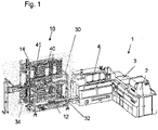
- the one in the figure 1 The arrangement shown shows a cigarette manufacturing machine combination 1 of the type PROTOS-M from the applicant, which essentially consists of a distributor unit 2, a rod unit 3 and a filter tipping machine 4, in connection with the storage arrangement 10 according to the invention in a second embodiment, namely with two 3-axis handling means 40, 41, wherein the container filling unit 12, the container emptying unit 14, the mass flow supply device 32 and the mass flow discharge device 34 are arranged in the same vertical plane.
- a switch cabinet for accommodating an operating and display unit and the control unit for the storage arrangement 10, which is not shown for the sake of clarity.
- the handling means 40, 41, the container filling unit 12, the container emptying unit 14, the mass flow supply device 32 and the mass flow discharge device 34 and the shelves 38 are detachably mounted on a common frame 30 of the storage arrangement according to the invention.
- Storage arrangements 10 shown are designed and set up for conveying and storing filter rods, multi-segment products, filter cigarettes in containers 16 .
- the storage arrangement 10 is also suitable for other rod-shaped and cuboid intermediate or end products, namely, for example, e-cigarettes, cardboard sleeves, tampons, tablet tubes, chocolate bars or similar rod-shaped or cylindrical products, as well as cigarette, dragee, cosmetic packs and blister strips or similar cuboid or strip-shaped products, to convey and store, the cuboid and strip-shaped products being advantageously conveyed in a single-layer mass flow.
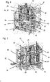
- the Figures 2 and 3 show a storage arrangement 10 according to the invention in a first embodiment, namely with only one 3-axis handling means 40, with the container filling unit 12, the container emptying unit 14, the mass flow feed device 32 and the mass flow discharge device 34 being arranged in the same vertical plane.
- the container filling unit 12 and the mass flow feed device 32 are designed to be movable and fixable together from the first transport level and second transport level vertically, in particular steplessly, into other transport levels, so that a step-free adjustment to the delivery height of a connecting machine arranged upstream, in particular to a cigarette making machine or a filter making machine.
- the container emptying unit 14 and the mass flow discharge device 34 are designed to be movable and fixable together from the third transport level and fourth transport level vertically, in particular steplessly, into other transport levels, so that a step-free adjustment to the entrance height of a connecting machine arranged downstream, in particular to a packaging machine, a multi-segment rod making machine or a filter rod transmitter unit.
- the term “container” with the reference number 6 is used both neutrally and comprehensively, as well as the term “full container” with the reference number 16, which is equivalent to a filled “container” 6. Accordingly, an empty “container " 6 also used as "empty container” with the reference number 18.
- a conveyor belt for empty containers 18, the so-called empty container accumulation belt 24, is arranged upstream of the container filling unit 12, the empty containers 18 being transported transversely, then temporarily stored and again isolated.
- the empty containers 18 are then fed individually transversely to a cleaning station 36 .
- the empty containers 18 are subsequently twice around their Longitudinal axis rotated by 180°, cleaned in the process and then transported transversely with the open side up into the container filling unit 12.
- empty containers 18 are first transported longitudinally, with a gap being closed to a container 6 that may be in front.
- the containers 6 are continuously filled with products during the conveying movement.
- the full container 16 formed in this way is continuously transported further in the longitudinal direction and a gap to a subsequent full container 16 is created by means of a separate belt drive.
- the container filling unit 12 is followed by a conveyor belt for full containers 16, the so-called full container accumulation belt 22, with the full containers 16 being pushed transversely from the downstream conveyor belt of the container filling unit 12 onto the full container accumulation belt 22, transported further transversely and temporarily stored. From the temporarily stored full containers 16, a full container block 26 is then formed for the takeover for the 3-axis handling means 40, also known as a 3-axis portal.
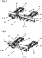
- FIG. 7 shows an enlarged representation of the container emptying unit 14 together with accumulation belts, the conveying and transport directions being indicated by means of arrows T, Q1 and Q2.
- a conveyor belt for full containers 16, the so-called full container accumulation belt 23, is arranged upstream of the container emptying unit 14, the full containers 16 being transported transversely, then temporarily stored and again separated. The full containers 16 are then individually transferred transversely into the container emptying unit 14 with the open side facing upwards.
- the full containers 16 are transported lengthwise, with a gap being closed to a full container 16 that may be running ahead.
- the containers are continuously emptied by means of a fork-shaped upward inclined conveyor 64 and fed to the mass flow discharge device 34 .
- the fork-shaped upward inclined conveyor 64 can have a preferably adjustable upper product guide for the product mass flow to be conveyed, particularly in the incline section.
- the upper product guide can be designed differently, in particular for different products.
- Fixed top guides fixed top guides with an articulated flap on the output side, fixed top guides with a flexible element on the output side, e.g. a so-called chain mail, a flexible self-adjusting top guide or a drivable flexible conveyor belt or output-side flexible element, e.g.
- An empty container 18 formed in this way is transported further in the longitudinal direction and at the same time a gap to a subsequent empty container 18 is created by means of a separate belt drive.
- a conveyor belt for empty containers 18, the so-called empty container accumulation belt 25, is arranged downstream of the container emptying unit 14, with the empty containers 18 being pushed transversely from the downstream conveyor belt of the container emptying unit 14 onto the empty container accumulation belt 25, immediately thereafter being transported further transversely and temporarily stored. From the intermediately stored empty containers 18, an empty container block 28 is formed directly for the 3-axis handling means 40 to take over.
- the 3-axis handling means 40 which is also referred to as a 3-axis portal, is used to transport the empty container blocks 28 and the full container blocks 26 between the shelves 38 and the empty container accumulation belts 24, 25 and the full container accumulation belts 22, 23.
- the 3-axis handling means 40 comprises a gripping means which removes an empty container block 28 from the shelf 38 and feeds it to the empty container accumulation belt 24 of the container filling unit 12 .
- the gripping means then takes over, for example, a full container block 26 from the full container accumulation conveyor 22 of the container filling unit 12 and guides the full container block 26 either to a shelf 38 or to the full container accumulation conveyor 23 of the container emptying unit 14 .
- the large number of other possible transport orders is organized accordingly and will not be described at this point.
- the Figures 4 and 5 show a storage arrangement 10 according to the invention in a second embodiment, namely with two 3-axis handling means 40, 41, with the container filling unit 12, the container emptying unit 14, the mass flow feed device 32 and the mass flow discharge device 34 being arranged in the same vertical plane.
- the functional groups of container filling unit 12, cleaning station 36, container emptying unit 14, full container dust conveyors 22, 23, empty container dust conveyors 22, 23 work as already described above for the storage arrangement 10 in the first embodiment, namely with a single 3-axis handling means 40, so that it is not presented again becomes.
- the difference in the second embodiment lies in the fact that the first (rear) handling means 40 is assigned to the container filling unit 12 and feeds this empty container blocks and transports full container blocks away.
- the second (front) handling means 41 is assigned to the container emptying unit and feeds this full container blocks and empty container blocks away.
Landscapes
- Manufacturing Of Cigar And Cigarette Tobacco (AREA)
- Attitude Control For Articles On Conveyors (AREA)
Claims (15)
- Agencement de stockage (10) pour acheminer, remplir et stocker des produits en forme de tiges et/ou en forme de parallélépipèdes ou des produits intermédiaires de l'industrie de transformation, notamment de l'industrie de transformation du tabac, tout en conservant la section transversale d'origine d'un flot massif de produits amené, comprenant au moins un magasin de réservoirs (20) pour entreposer une pluralité de réservoirs (6) dans des compartiments d'étagères (38), au moins une unité de remplissage de réservoirs (12) pour remplir les réservoirs (6) de produits, au moins un moyen de manipulation (40, 41) pour manipuler les réservoirs (6) ainsi qu'au moins une unité de vidage de réservoirs (14) pour vider les réservoirs (6) entreposés dans le magasin de réservoirs (20), le magasin de réservoirs (20) présentant une structure (30) sur laquelle l'au moins un moyen de manipulation, l'au moins une unité de remplissage de réservoirs (12) et/ou l'au moins une unité de vidage de réservoirs (14) sont supportées, et une pluralité de compartiments d'étagères (38) dans au moins huit, de préférence au moins dix plans d'entreposage horizontaux, étant agencés sur la structure, un dispositif d'amenée de flot massif (32) étant disposé en amont de la ou de chaque unité de remplissage de réservoirs (12), l'unité de remplissage de réservoirs (12) présentant un premier élément d'acheminement dans un premier plan de transport horizontal et le dispositif d'amenée de flot massif (32) présentant un deuxième élément d'acheminement dans un deuxième plan de transport horizontal, qui est agencé en amont, au-dessus et au voisinage du premier élément d'acheminement dans le premier plan de transport horizontal, le premier élément d'acheminement étant agencé dans le premier plan de transport en dessous du deuxième plan de transport et avec essentiellement la même direction de transport que le flot massif de produits pour l'acheminement continu de réservoirs vides (6) dans leur extension longitudinale avec un panneau frontal en avant dans la direction de transport horizontale T, le deuxième élément d'acheminement du dispositif d'amenée de flot massif (32) étant agencé dans le deuxième plan de transport pour l'acheminement continu du flot massif de produits dans la direction de transport horizontale T, et l'agencement comprenant un conduit qui relie le deuxième plan de transport supérieur au premier plan de transport inférieur pour remplir les réservoirs pendant le transport continu des réservoirs (6) et du flot massif de produits, de telle sorte que le flot massif de produits est divisé en portions approximativement égales et rempli dans les réservoirs (6).
- Agencement de stockage (10) selon la revendication 1, caractérisé en ce que l'unité de remplissage de réservoirs (12) et le dispositif d'amenée de flot massif (32) sont configurés de manière à pouvoir être déplacés et fixés ensemble verticalement, notamment en continu, à partir du premier plan de transport et du deuxième plan de transport vers d'autres plans de transport, de telle sorte qu'une adaptation sans palier à la hauteur de distribution d'une machine de raccordement agencée en amont peut être réalisée.
- Agencement de stockage (10) selon la revendication 1 ou 2, caractérisé en ce que la ou chaque unité de vidage de réservoirs (14) est suivie en aval par un dispositif d'évacuation de flot massif (34), l'unité de vidage de réservoirs (14) présentant un troisième élément d'acheminement dans un troisième plan de transport horizontal et le dispositif d'évacuation de flot massif (34) présentant un quatrième élément d'acheminement dans un quatrième plan de transport horizontal, qui est agencé en aval, au-dessus et au voisinage du troisième élément d'acheminement dans le troisième plan de transport horizontal, et l'unité de vidage de réservoirs (14) et le dispositif d'évacuation de flot massif (34) étant configurés pour être déplacés et fixés ensemble verticalement, notamment en continu, à partir du troisième plan de transport et du quatrième plan de transport vers d'autres plans de transport, de telle sorte qu'une adaptation sans palier à la hauteur d'entrée d'une machine de raccordement agencée en aval peut être réalisée.
- Agencement de stockage (10) selon la revendication 2, caractérisé en ce que le deuxième élément d'acheminement du dispositif d'amenée de flot massif (32) est suivi, dans le deuxième plan de transport horizontal, par un élément d'acheminement incliné vers le bas dans un plan de transport oblique selon un angle de 15 à 60 degrés, qui se termine au-dessus du premier plan de transport horizontal de l'unité de remplissage de réservoirs (12).
- Agencement de stockage (10) selon la revendication 3, caractérisé en ce que l'élément d'acheminement du dispositif d'évacuation de flot massif (34) est précédé, dans le quatrième plan de transport horizontal, par un élément d'acheminement incliné dans un plan de transport oblique selon un angle de 15 à 60 degrés, qui se termine au-dessus du troisième plan de transport horizontal de l'unité de vidage de réservoirs (14).
- Agencement de stockage (10) selon l'une quelconque des revendications 1 à 5, caractérisé en ce que l'unité de vidage de réservoirs (14) est agencée au-dessus de l'unité de remplissage de réservoirs (12) et, de préférence, l'unité de remplissage de réservoirs (12) et l'unité de vidage de réservoirs (14) sont agencées essentiellement dans le même plan vertical.
- Agencement de stockage (10) selon la revendication 6, caractérisé en ce que le dispositif d'amenée de flot massif (32) et le dispositif d'évacuation de flot massif (34) peuvent être reliés au moyen d'un convoyeur ascendant afin de réaliser un fonctionnement en continu.
- Agencement de stockage (10) selon l'une quelconque des revendications 1 à 7, caractérisé en ce que l'unité de remplissage de réservoirs (12) est précédée par une bande d'accumulation de réservoirs vides (24) et une station de nettoyage (36) qui comprend un dispositif de retournement des paquets pour les réservoirs vides (18).
- Agencement de stockage (10) selon l'une quelconque des revendications 1 à 8, caractérisé en ce que l'agencement de stockage (10) présente un moyen de manipulation (40) avec un axe linéaire X qui présente un entraînement horizontal, avec un axe linéaire Y qui présente un entraînement de moyen de préhension et avec un axe linéaire Z qui présente un entraînement vertical (52), à chacun desquels est associé un servomécanisme pouvant être commandé séparément, le moyen de manipulation (40) présentant un moyen de préhension qui est configuré et adapté pour saisir et transporter les réservoirs (6) par blocs, notamment sous forme de bloc de réservoirs pleins (26) ou de bloc de réservoirs vides (28).
- Agencement de stockage (10) selon l'une quelconque des revendications 1 à 8, caractérisé en ce que l'agencement de stockage (10) présente un premier et un deuxième moyen de manipulation (40, 41) avec respectivement un axe linéaire X1, X2 qui présentent respectivement un entraînement horizontal (55), avec respectivement un axe linéaire Y1, Y2 qui présentent respectivement un entraînement de moyen de préhension et avec respectivement un axe linéaire Z1, Z2, qui présentent respectivement un entraînement vertical (52), à chacun desquels est associé un servomécanisme pouvant être commandé séparément, chaque moyen de manipulation (40, 41) présentant un moyen de préhension qui est configuré et adapté pour saisir et transporter les réservoirs (6) par blocs, notamment sous forme de bloc de réservoirs pleins (26) ou de bloc de réservoirs vides (28).
- Agencement de stockage (10) selon l'une quelconque des revendications 1 à 10, caractérisé en ce que l'agencement de stockage (10) présente une unité de contrôle et une unité de commande et de visualisation qui sont configurées et adaptées pour contrôler un suivi de produit et/ou un fonctionnement multimarque et/ou un changement de marque, l'état d'occupation de chaque compartiment d'étagère (38), notamment en ce qui concerne la durée de séjour et le contenu des réservoirs (6) dans le compartiment d'étagère respectif (38), pouvant être mémorisé dans l'unité de contrôle et affiché sur l'unité de commande et de visualisation, l'unité de contrôle et l'unité de commande et de visualisation étant de préférence configurées comme une seule unité de construction.
- Agencement de stockage (10) selon l'une quelconque des revendications 1, 2, 4 et 8 à 10, caractérisé en ce que l'agencement de stockage (10) présente un convoyeur d'entrée pour les réservoirs vides (18) et un convoyeur de sortie pour les réservoirs pleins (16), afin d'introduire et d'extraire des réservoirs (6) dans l'agencement de stockage (10), notamment en cas de changement de format.
- Procédé pour acheminer, remplir et stocker des produits en forme de tiges et en forme de parallélépipèdes, notamment des produits intermédiaires de l'industrie de transformation, notamment de l'industrie de transformation du tabac, tout en conservant la section transversale d'origine du flot massif de produits amené, dans des réservoirs (6), et transférer les réservoirs remplis (6) dans un magasin de réservoirs (20) pour entreposer une pluralité de réservoirs (6) dans une pluralité de compartiments d'étagères (38), comprenant les étapes suivantes :- l'acheminement continu de réservoirs vides (6) dans leur extension longitudinale avec un panneau frontal en avant dans la direction de transport horizontale T sur un premier élément d'acheminement dans un premier plan de transport en dessous d'un deuxième plan de transport et avec essentiellement la même direction d'acheminement que le flot massif de produits,- l'acheminement continu d'un flot massif de produits dans la direction de transport horizontale T sur un deuxième élément d'acheminement d'un dispositif d'amenée de flot massif (32) dans un deuxième plan de transport ;- le remplissage des réservoirs (6) pendant le transport continu des réservoirs (6) et du flot massif de produits dans un conduit qui relie le deuxième plan de transport supérieur au premier plan de transport inférieur, de telle sorte que le flot massif de produits est divisé en portions approximativement égales et rempli dans les réservoirs (6),- l'accélération des réservoirs remplis (6) de manière à créer un espace vide avec le réservoir suivant (6),- le ralentissement des réservoirs (6) remplis de produits,- l'acheminement des réservoirs (6) remplis de produits avec une paroi latérale en avant dans la direction de transport horizontale Q1, transversalement à la direction de transport T, sur un troisième élément d'acheminement, notamment sur une première bande d'accumulation de réservoirs pleins (22),- le regroupement des réservoirs remplis (6) en une formation de bloc avec au moins deux réservoirs remplis (6) en un bloc de réservoirs pleins (26),- l'acheminement du bloc de réservoirs pleins (26) au moyen d'un moyen de manipulation (40) vers un compartiment d'étagère libre (38) du magasin de réservoirs (20),- l'acheminement du bloc de réservoirs pleins (26) au moyen du moyen de manipulation (40) à partir d'un compartiment d'étagère (38) du magasin de réservoirs (20) vers un quatrième élément d'acheminement, notamment vers une deuxième bande d'accumulation de réservoirs pleins (23), dans un troisième plan de transport,- la séparation des réservoirs remplis (6) d'un bloc de réservoirs pleins (26) dans la direction de transport horizontale Q2, transversalement à la direction de transport T, de telle sorte que les parois latérales des réservoirs remplis (6) sont au moins légèrement espacées, et- l'acheminement des réservoirs remplis (6) transversalement à la direction de transport Q2 vers une unité de vidage de réservoirs (14).
- Procédé selon la revendication 13, caractérisé par les étapes supplémentaires suivantes :- l'acheminement des réservoirs (6) remplis de produits dans leur extension longitudinale avec un panneau frontal en avant dans la direction de transport horizontale T, dans un troisième plan de transport, vers une unité de vidage de réservoirs (14),- le vidage des réservoirs (6) pendant le transport continu des réservoirs (6) au moyen d'un convoyeur ascendant oblique (64) et le transfert des produits dans un flot massif de produits d'un dispositif d'évacuation de flot massif (34) dans un quatrième plan de transport,- l'accélération des réservoirs vides (6) de manière à créer un espace vide avec le réservoir suivant (6),- le ralentissement des réservoirs vides (6),- l'acheminement des réservoirs vides (6) avec une paroi latérale en avant dans la direction de transport horizontale Q1, transversalement à la direction de transport T, sur un cinquième élément d'acheminement, notamment une première bande d'accumulation de réservoirs vides (25),- le regroupement des réservoirs vides (6) en une formation de bloc avec au moins deux réservoirs vides (6) en un bloc de réservoirs vides (28),- l'acheminement du bloc de réservoirs vides (28) au moyen d'un moyen de manipulation (40, 41) vers un compartiment d'étagère libre (38) du magasin de réservoirs (20) ou- l'acheminement du bloc de réservoirs vides (28) au moyen du moyen de manipulation (40, 41) à partir d'un compartiment d'étagère (38) du magasin de réservoirs (20) vers un sixième élément d'acheminement, notamment vers un deuxième bande d'accumulation de réservoirs vides (24), dans un cinquième plan de transport,- la séparation des réservoirs vides (6) à partir d'un bloc de réservoirs vides (28) dans la direction de transport horizontale Q2 transversalement à la direction de transport T, de telle sorte que les parois latérales des réservoirs vides (6) sont au moins légèrement espacées, et- l'acheminement des réservoirs vides (6) transversalement à la direction de transport Q2 vers une unité de remplissage de réservoirs (12).
- Procédé selon la revendication 14, caractérisé en ce que le procédé comprend, avant l'étape suivante :- l'acheminement des réservoirs vides (6) transversalement à la direction de transport Q2 vers une unité de remplissage de réservoirs (12),- les étapes suivantes :- l'acheminement des réservoirs vides (6) ouverts vers le haut transversalement à la direction de transport T vers une station de nettoyage (36),- la rotation des réservoirs (6) de 180° autour de leur axe longitudinal,- le nettoyage des réservoirs (6),- la rotation des réservoirs nettoyés (6) de 180° autour de leur axe longitudinal, et- le transfert des réservoirs vides (6) ouverts vers le haut sur un élément d'acheminement dans le premier plan de transport.
Priority Applications (1)
| Application Number | Priority Date | Filing Date | Title |
|---|---|---|---|
| CN201610581623.1A CN106562472B (zh) | 2014-10-24 | 2016-07-22 | 用于输送并储存加工业的棒形的和/或方形的产品的装置和方法 |
Applications Claiming Priority (2)
| Application Number | Priority Date | Filing Date | Title |
|---|---|---|---|
| DE102014115532 | 2014-10-24 | ||
| DE102014116578.0A DE102014116578A1 (de) | 2014-10-24 | 2014-11-13 | Anordnung und Verfahren zum Fördern eines aus stabförmigen Artikeln der Tabak verarbeitenden Industrie gebildeten Produktmassenstroms sowie Behälter zur Aufnahme und Abgabe von Portionen des Produktmassenstroms |
Publications (3)
| Publication Number | Publication Date |
|---|---|
| EP3020287A2 EP3020287A2 (fr) | 2016-05-18 |
| EP3020287A3 EP3020287A3 (fr) | 2016-08-24 |
| EP3020287B1 true EP3020287B1 (fr) | 2022-11-02 |
Family
ID=53783013
Family Applications (2)
| Application Number | Title | Priority Date | Filing Date |
|---|---|---|---|
| EP15002182.2A Active EP3020287B1 (fr) | 2014-10-24 | 2015-07-23 | Agencement et procédé pour acheminer et stocker des produits en forme de tiges et/ou parallélépipèdes de l'industrie de transformation, notamment de l'industrie de transformation du tabac |
| EP15191004.9A Active EP3011845B1 (fr) | 2014-10-24 | 2015-10-22 | Agencement et procede d'acheminement d'un flux massique de produits forme d'articles en forme de tige de l'industrie de transformation du tabac |
Family Applications After (1)
| Application Number | Title | Priority Date | Filing Date |
|---|---|---|---|
| EP15191004.9A Active EP3011845B1 (fr) | 2014-10-24 | 2015-10-22 | Agencement et procede d'acheminement d'un flux massique de produits forme d'articles en forme de tige de l'industrie de transformation du tabac |
Country Status (2)
| Country | Link |
|---|---|
| EP (2) | EP3020287B1 (fr) |
| PL (2) | PL3020287T3 (fr) |
Families Citing this family (1)
| Publication number | Priority date | Publication date | Assignee | Title |
|---|---|---|---|---|
| DE102018112009A1 (de) * | 2018-05-18 | 2019-11-21 | Hauni Maschinenbau Gmbh | Verfahren zum Entfernen von stabförmigen Artikeln der Tabak verarbeitenden Industrie aus einem Transportkanal mittels eines Räummittels |
Family Cites Families (17)
| Publication number | Priority date | Publication date | Assignee | Title |
|---|---|---|---|---|
| DE450897C (de) * | 1927-10-12 | Muller J C & Co | Mit einer Zigarettenstrangmaschine in Verbindung stehende Zigarettenschragenfuellvorrichtung | |
| BE616630A (fr) * | 1961-04-24 | 1962-08-16 | Seita | Appareil de rangement dans des réceptacles d'objets en forme de tiges et notamment de cigarettes |
| DE1263564B (de) * | 1961-09-01 | 1968-03-14 | Reemtsma H F & Ph | Zigarettenschragen |
| GB1455257A (en) * | 1973-01-30 | 1976-11-10 | Molins Ltd | Trays for cigarettes |
| IT1023641B (it) * | 1974-12-11 | 1978-05-30 | Gd Spa | Apparecchiatura automatica per il trasferpimento dei comtenitori di sigarette dai dispositivi preposti al loro riempimento ai meccanismi di caricamento telle tramogge delle macchine condizionatrici di sigarette in pacchetti |
| GB2008526B (en) | 1977-09-10 | 1982-05-06 | Molins Ltd | Method and apparatus for unloading containers of rod-ilke articles |
| US5190428A (en) * | 1986-02-25 | 1993-03-02 | Molins Machine Company, Inc. | Conveyor system for rod-like articles |
| JPH07115703B2 (ja) * | 1988-03-18 | 1995-12-13 | 株式会社東京自働機械製作所 | 棒状物供給方法及びその装置 |
| DE3924098C2 (de) * | 1989-07-20 | 1998-05-20 | Hauni Werke Koerber & Co Kg | Behälterfördervorrichtung |
| GB2249533A (en) * | 1990-11-09 | 1992-05-13 | Koerber Ag | Apparatus for manipulating trays for cigarettes and the like |
| DE10051790A1 (de) * | 2000-10-18 | 2002-04-25 | Hauni Maschinenbau Ag | Behälter, Vorrichtung und Verfahren zum Transportieren von stabförmigen Artikeln der tabakverarbeitenden Industrie |
| DE102005033907A1 (de) | 2005-07-15 | 2007-01-18 | Hauni Maschinenbau Ag | Vorrichtung und Verfahren zum Transportieren von einen Massenstrom bildenden Artikeln sowie Vorrichtung zum Befüllen einer nachgeordneten Vorrichtung mit stabförmigen Artikeln |
| DE102006049160B3 (de) * | 2006-10-18 | 2008-02-28 | Bodensohn Präzision GmbH | Lagervorrichtung für lose zuführbare Gegenstände |
| PL212816B1 (pl) | 2008-05-29 | 2012-11-30 | Int Tobacco Machinery Poland | Uklad urzadzen do transportu elementów pretopodobnych w instalacji produkcyjnej przemyslu tytoniowego |
| PL212815B1 (pl) * | 2008-05-29 | 2012-11-30 | Int Tobacco Machinery Poland | Urzadzenie do rozladowywania wypelnionych elementami pretopodobnymi kaset wielosegmentowych stosowanych w przemysle tytoniowym |
| DE102011010257A1 (de) * | 2011-01-26 | 2012-07-26 | Hauni Maschinenbau Ag | Anordnung und Verfahren zum Produzieren und Speichern stabförmiger Halbfertigprodukte der Tabak verarbeitenden Industrie |
| DE102011054310A1 (de) * | 2011-10-07 | 2013-04-11 | Hauni Maschinenbau Ag | Anordnung zum Herstellen, Speichern und Transportieren von Produkten der Tabak verarbeitenden Industrie |
-
2015
- 2015-07-23 PL PL15002182.2T patent/PL3020287T3/pl unknown
- 2015-07-23 EP EP15002182.2A patent/EP3020287B1/fr active Active
- 2015-10-22 PL PL15191004.9T patent/PL3011845T3/pl unknown
- 2015-10-22 EP EP15191004.9A patent/EP3011845B1/fr active Active
Also Published As
| Publication number | Publication date |
|---|---|
| EP3011845A1 (fr) | 2016-04-27 |
| PL3020287T3 (pl) | 2023-03-27 |
| EP3020287A3 (fr) | 2016-08-24 |
| EP3020287A2 (fr) | 2016-05-18 |
| EP3011845B1 (fr) | 2025-03-12 |
| PL3011845T3 (pl) | 2025-07-28 |
Similar Documents
| Publication | Publication Date | Title |
|---|---|---|
| EP1100629B1 (fr) | Dispositif permettant de vider des conteneurs de plis | |
| EP2763918B1 (fr) | Procédé et dispositif de transport de produits en forme de bandes ou de plaques | |
| CN106562472B (zh) | 用于输送并储存加工业的棒形的和/或方形的产品的装置和方法 | |
| AT405640B (de) | Kommissionieranlage | |
| DE69318303T2 (de) | Fördervorrichtung in einer Wurstverpackungsmaschine | |
| CH709841A1 (de) | Übergabeeinrichtung zur Übergabe länglicher, mindestens annähernd hohlzylindrischer Produkteinheiten auf ein Transportband zur Belieferung einer Abpackeinheit. | |
| DE3917097A1 (de) | Behaelterfoerdervorrichtung | |
| EP1162146B1 (fr) | Procédé et dispositif pour former et emballer des groupes d'objets individuels | |
| EP2150138B1 (fr) | Magasin de vidage et dispositif de transfert pour dispositif de vidage de caissons, ainsi que dispositif de vidage de caissons | |
| EP2480468B1 (fr) | Dispositif de stockage à grande vitesse | |
| EP2384652A2 (fr) | Dispositif de remplissage de combles avec des articles en forme de tiges et machine de fabrication pour articles en forme de tiges dotée d'un tel dispositif | |
| EP2859802A1 (fr) | Dispositif et procédé de transport et de tri d'articles à fumer | |
| DE69725799T2 (de) | Einheit zum Bilden von Zigarettengruppen | |
| EP3020287A2 (fr) | Système et procède de transport et de stockage de produits en forme de tige et/ou carrée de l'industrie de traitement, en particulier de l'industrie de traitement du tabac | |
| EP2759216A1 (fr) | Dispositif de vidage de casiers et procédé de vidage automatique de casiers remplis d'articles en forme de tiges dans une machine de production de l'industrie de traitement du tabac, et système de production doté d'une machine de production et d'au moins deux dispositifs de vidage de casiers | |
| DE2716391B2 (de) | Verfahren zum Herstellen und Verpacken von Filterzigaretten sowie Vorrichtung zum Durchführen des Verfahrens | |
| DE3013014C2 (fr) | ||
| DE29818434U1 (de) | Vorrichtung zum Behandeln von Flaschen | |
| DE102005051525B4 (de) | Filterzuführeinrichtung | |
| DE19506031C1 (de) | Verfahren zum Speichern von Fördergut und Einrichtung zur Durchführung des Verfahrens | |
| EP3135128A2 (fr) | Station de vidage de baquets destinée à vider des baquets remplis de produits en forme de tige et procédé pour vider des baquets remplis de produits en forme de tige à l'aide d'une station de vidage de baquets | |
| DE102005034245A1 (de) | Vorrichtung und Verfahren zum Transportieren eines aus stabförmigen Artikeln gebildeten einlagigen Massenstroms | |
| DE2743266C2 (de) | Speichervorrichtung für Zigaretten und ähnliche stabförmige Gegenstände der tabakverarbeitenden Industrie | |
| WO2013178620A1 (fr) | Dispositif et procédé de fabrication de tiges d'articles composées de matériau fibreux gainé dans l'industrie du tabac | |
| EP2481304A1 (fr) | Alimentation de produits en forme de tiges de l'industrie de traitement du tabac dans une cartouche |
Legal Events
| Date | Code | Title | Description |
|---|---|---|---|
| PUAI | Public reference made under article 153(3) epc to a published international application that has entered the european phase |
Free format text: ORIGINAL CODE: 0009012 |
|
| AK | Designated contracting states |
Kind code of ref document: A2 Designated state(s): AL AT BE BG CH CY CZ DE DK EE ES FI FR GB GR HR HU IE IS IT LI LT LU LV MC MK MT NL NO PL PT RO RS SE SI SK SM TR |
|
| AX | Request for extension of the european patent |
Extension state: BA ME |
|
| RAP1 | Party data changed (applicant data changed or rights of an application transferred) |
Owner name: HAUNI MASCHINENBAU GMBH |
|
| PUAL | Search report despatched |
Free format text: ORIGINAL CODE: 0009013 |
|
| AK | Designated contracting states |
Kind code of ref document: A3 Designated state(s): AL AT BE BG CH CY CZ DE DK EE ES FI FR GB GR HR HU IE IS IT LI LT LU LV MC MK MT NL NO PL PT RO RS SE SI SK SM TR |
|
| AX | Request for extension of the european patent |
Extension state: BA ME |
|
| RIC1 | Information provided on ipc code assigned before grant |
Ipc: A24C 5/354 20060101ALI20160715BHEP Ipc: A24C 5/358 20060101ALI20160715BHEP Ipc: A24C 5/352 20060101AFI20160715BHEP Ipc: B65B 19/04 20060101ALN20160715BHEP |
|
| STAA | Information on the status of an ep patent application or granted ep patent |
Free format text: STATUS: REQUEST FOR EXAMINATION WAS MADE |
|
| 17P | Request for examination filed |
Effective date: 20161124 |
|
| RBV | Designated contracting states (corrected) |
Designated state(s): AL AT BE BG CH CY CZ DE DK EE ES FI FR GB GR HR HU IE IS IT LI LT LU LV MC MK MT NL NO PL PT RO RS SE SI SK SM TR |
|
| STAA | Information on the status of an ep patent application or granted ep patent |
Free format text: STATUS: EXAMINATION IS IN PROGRESS |
|
| 17Q | First examination report despatched |
Effective date: 20210506 |
|
| RIC1 | Information provided on ipc code assigned before grant |
Ipc: B65B 19/04 20060101ALN20220405BHEP Ipc: A24C 5/354 20060101ALI20220405BHEP Ipc: A24C 5/352 20060101AFI20220405BHEP |
|
| GRAP | Despatch of communication of intention to grant a patent |
Free format text: ORIGINAL CODE: EPIDOSNIGR1 |
|
| STAA | Information on the status of an ep patent application or granted ep patent |
Free format text: STATUS: GRANT OF PATENT IS INTENDED |
|
| INTG | Intention to grant announced |
Effective date: 20220524 |
|
| RIN1 | Information on inventor provided before grant (corrected) |
Inventor name: HENNING, AXEL Inventor name: BUDNY, PIOTR Inventor name: WERDER, STEPHAN Inventor name: KOLANUS, MARTIN Inventor name: GLAESER, RALF Inventor name: BLUETHGEN, SOENKE CHRISTIAN Inventor name: KREYSERN, JAN Inventor name: BUSSE-RIEPSHOFF, UWE |
|
| GRAS | Grant fee paid |
Free format text: ORIGINAL CODE: EPIDOSNIGR3 |
|
| GRAA | (expected) grant |
Free format text: ORIGINAL CODE: 0009210 |
|
| STAA | Information on the status of an ep patent application or granted ep patent |
Free format text: STATUS: THE PATENT HAS BEEN GRANTED |
|
| REG | Reference to a national code |
Ref country code: DE Ref legal event code: R081 Ref document number: 502015016134 Country of ref document: DE Owner name: KOERBER TECHNOLOGIES GMBH, DE Free format text: FORMER OWNER: HAUNI MASCHINENBAU GMBH, 21033 HAMBURG, DE |
|
| AK | Designated contracting states |
Kind code of ref document: B1 Designated state(s): AL AT BE BG CH CY CZ DE DK EE ES FI FR GB GR HR HU IE IS IT LI LT LU LV MC MK MT NL NO PL PT RO RS SE SI SK SM TR |
|
| REG | Reference to a national code |
Ref country code: GB Ref legal event code: FG4D Free format text: NOT ENGLISH |
|
| REG | Reference to a national code |
Ref country code: CH Ref legal event code: EP Ref country code: AT Ref legal event code: REF Ref document number: 1528088 Country of ref document: AT Kind code of ref document: T Effective date: 20221115 |
|
| REG | Reference to a national code |
Ref country code: DE Ref legal event code: R096 Ref document number: 502015016134 Country of ref document: DE |
|
| REG | Reference to a national code |
Ref country code: IE Ref legal event code: FG4D Free format text: LANGUAGE OF EP DOCUMENT: GERMAN |
|
| RAP4 | Party data changed (patent owner data changed or rights of a patent transferred) |
Owner name: KOERBER TECHNOLOGIES GMBH |
|
| REG | Reference to a national code |
Ref country code: NL Ref legal event code: FP |
|
| REG | Reference to a national code |
Ref country code: LT Ref legal event code: MG9D |
|
| PG25 | Lapsed in a contracting state [announced via postgrant information from national office to epo] |
Ref country code: SE Free format text: LAPSE BECAUSE OF FAILURE TO SUBMIT A TRANSLATION OF THE DESCRIPTION OR TO PAY THE FEE WITHIN THE PRESCRIBED TIME-LIMIT Effective date: 20221102 Ref country code: PT Free format text: LAPSE BECAUSE OF FAILURE TO SUBMIT A TRANSLATION OF THE DESCRIPTION OR TO PAY THE FEE WITHIN THE PRESCRIBED TIME-LIMIT Effective date: 20230302 Ref country code: NO Free format text: LAPSE BECAUSE OF FAILURE TO SUBMIT A TRANSLATION OF THE DESCRIPTION OR TO PAY THE FEE WITHIN THE PRESCRIBED TIME-LIMIT Effective date: 20230202 Ref country code: LT Free format text: LAPSE BECAUSE OF FAILURE TO SUBMIT A TRANSLATION OF THE DESCRIPTION OR TO PAY THE FEE WITHIN THE PRESCRIBED TIME-LIMIT Effective date: 20221102 Ref country code: FI Free format text: LAPSE BECAUSE OF FAILURE TO SUBMIT A TRANSLATION OF THE DESCRIPTION OR TO PAY THE FEE WITHIN THE PRESCRIBED TIME-LIMIT Effective date: 20221102 Ref country code: ES Free format text: LAPSE BECAUSE OF FAILURE TO SUBMIT A TRANSLATION OF THE DESCRIPTION OR TO PAY THE FEE WITHIN THE PRESCRIBED TIME-LIMIT Effective date: 20221102 |
|
| PG25 | Lapsed in a contracting state [announced via postgrant information from national office to epo] |
Ref country code: RS Free format text: LAPSE BECAUSE OF FAILURE TO SUBMIT A TRANSLATION OF THE DESCRIPTION OR TO PAY THE FEE WITHIN THE PRESCRIBED TIME-LIMIT Effective date: 20221102 Ref country code: LV Free format text: LAPSE BECAUSE OF FAILURE TO SUBMIT A TRANSLATION OF THE DESCRIPTION OR TO PAY THE FEE WITHIN THE PRESCRIBED TIME-LIMIT Effective date: 20221102 Ref country code: IS Free format text: LAPSE BECAUSE OF FAILURE TO SUBMIT A TRANSLATION OF THE DESCRIPTION OR TO PAY THE FEE WITHIN THE PRESCRIBED TIME-LIMIT Effective date: 20230302 Ref country code: HR Free format text: LAPSE BECAUSE OF FAILURE TO SUBMIT A TRANSLATION OF THE DESCRIPTION OR TO PAY THE FEE WITHIN THE PRESCRIBED TIME-LIMIT Effective date: 20221102 Ref country code: GR Free format text: LAPSE BECAUSE OF FAILURE TO SUBMIT A TRANSLATION OF THE DESCRIPTION OR TO PAY THE FEE WITHIN THE PRESCRIBED TIME-LIMIT Effective date: 20230203 |
|
| P01 | Opt-out of the competence of the unified patent court (upc) registered |
Effective date: 20230616 |
|
| PG25 | Lapsed in a contracting state [announced via postgrant information from national office to epo] |
Ref country code: SM Free format text: LAPSE BECAUSE OF FAILURE TO SUBMIT A TRANSLATION OF THE DESCRIPTION OR TO PAY THE FEE WITHIN THE PRESCRIBED TIME-LIMIT Effective date: 20221102 Ref country code: RO Free format text: LAPSE BECAUSE OF FAILURE TO SUBMIT A TRANSLATION OF THE DESCRIPTION OR TO PAY THE FEE WITHIN THE PRESCRIBED TIME-LIMIT Effective date: 20221102 Ref country code: EE Free format text: LAPSE BECAUSE OF FAILURE TO SUBMIT A TRANSLATION OF THE DESCRIPTION OR TO PAY THE FEE WITHIN THE PRESCRIBED TIME-LIMIT Effective date: 20221102 Ref country code: DK Free format text: LAPSE BECAUSE OF FAILURE TO SUBMIT A TRANSLATION OF THE DESCRIPTION OR TO PAY THE FEE WITHIN THE PRESCRIBED TIME-LIMIT Effective date: 20221102 Ref country code: CZ Free format text: LAPSE BECAUSE OF FAILURE TO SUBMIT A TRANSLATION OF THE DESCRIPTION OR TO PAY THE FEE WITHIN THE PRESCRIBED TIME-LIMIT Effective date: 20221102 |
|
| REG | Reference to a national code |
Ref country code: DE Ref legal event code: R097 Ref document number: 502015016134 Country of ref document: DE |
|
| PG25 | Lapsed in a contracting state [announced via postgrant information from national office to epo] |
Ref country code: SK Free format text: LAPSE BECAUSE OF FAILURE TO SUBMIT A TRANSLATION OF THE DESCRIPTION OR TO PAY THE FEE WITHIN THE PRESCRIBED TIME-LIMIT Effective date: 20221102 Ref country code: AL Free format text: LAPSE BECAUSE OF FAILURE TO SUBMIT A TRANSLATION OF THE DESCRIPTION OR TO PAY THE FEE WITHIN THE PRESCRIBED TIME-LIMIT Effective date: 20221102 |
|
| PLBE | No opposition filed within time limit |
Free format text: ORIGINAL CODE: 0009261 |
|
| STAA | Information on the status of an ep patent application or granted ep patent |
Free format text: STATUS: NO OPPOSITION FILED WITHIN TIME LIMIT |
|
| 26N | No opposition filed |
Effective date: 20230803 |
|
| PG25 | Lapsed in a contracting state [announced via postgrant information from national office to epo] |
Ref country code: SI Free format text: LAPSE BECAUSE OF FAILURE TO SUBMIT A TRANSLATION OF THE DESCRIPTION OR TO PAY THE FEE WITHIN THE PRESCRIBED TIME-LIMIT Effective date: 20221102 |
|
| PG25 | Lapsed in a contracting state [announced via postgrant information from national office to epo] |
Ref country code: MC Free format text: LAPSE BECAUSE OF FAILURE TO SUBMIT A TRANSLATION OF THE DESCRIPTION OR TO PAY THE FEE WITHIN THE PRESCRIBED TIME-LIMIT Effective date: 20221102 |
|
| PG25 | Lapsed in a contracting state [announced via postgrant information from national office to epo] |
Ref country code: MC Free format text: LAPSE BECAUSE OF FAILURE TO SUBMIT A TRANSLATION OF THE DESCRIPTION OR TO PAY THE FEE WITHIN THE PRESCRIBED TIME-LIMIT Effective date: 20221102 |
|
| REG | Reference to a national code |
Ref country code: CH Ref legal event code: PL |
|
| REG | Reference to a national code |
Ref country code: BE Ref legal event code: MM Effective date: 20230731 |
|
| PG25 | Lapsed in a contracting state [announced via postgrant information from national office to epo] |
Ref country code: LU Free format text: LAPSE BECAUSE OF NON-PAYMENT OF DUE FEES Effective date: 20230723 |
|
| GBPC | Gb: european patent ceased through non-payment of renewal fee |
Effective date: 20230723 |
|
| PG25 | Lapsed in a contracting state [announced via postgrant information from national office to epo] |
Ref country code: LU Free format text: LAPSE BECAUSE OF NON-PAYMENT OF DUE FEES Effective date: 20230723 |
|
| REG | Reference to a national code |
Ref country code: IE Ref legal event code: MM4A |
|
| PG25 | Lapsed in a contracting state [announced via postgrant information from national office to epo] |
Ref country code: GB Free format text: LAPSE BECAUSE OF NON-PAYMENT OF DUE FEES Effective date: 20230723 Ref country code: CH Free format text: LAPSE BECAUSE OF NON-PAYMENT OF DUE FEES Effective date: 20230731 |
|
| PG25 | Lapsed in a contracting state [announced via postgrant information from national office to epo] |
Ref country code: FR Free format text: LAPSE BECAUSE OF NON-PAYMENT OF DUE FEES Effective date: 20230731 Ref country code: BE Free format text: LAPSE BECAUSE OF NON-PAYMENT OF DUE FEES Effective date: 20230731 |
|
| PG25 | Lapsed in a contracting state [announced via postgrant information from national office to epo] |
Ref country code: IE Free format text: LAPSE BECAUSE OF NON-PAYMENT OF DUE FEES Effective date: 20230723 |
|
| PG25 | Lapsed in a contracting state [announced via postgrant information from national office to epo] |
Ref country code: IE Free format text: LAPSE BECAUSE OF NON-PAYMENT OF DUE FEES Effective date: 20230723 |
|
| REG | Reference to a national code |
Ref country code: AT Ref legal event code: MM01 Ref document number: 1528088 Country of ref document: AT Kind code of ref document: T Effective date: 20230723 |
|
| PG25 | Lapsed in a contracting state [announced via postgrant information from national office to epo] |
Ref country code: AT Free format text: LAPSE BECAUSE OF NON-PAYMENT OF DUE FEES Effective date: 20230723 |
|
| PG25 | Lapsed in a contracting state [announced via postgrant information from national office to epo] |
Ref country code: AT Free format text: LAPSE BECAUSE OF NON-PAYMENT OF DUE FEES Effective date: 20230723 |
|
| PG25 | Lapsed in a contracting state [announced via postgrant information from national office to epo] |
Ref country code: BG Free format text: LAPSE BECAUSE OF FAILURE TO SUBMIT A TRANSLATION OF THE DESCRIPTION OR TO PAY THE FEE WITHIN THE PRESCRIBED TIME-LIMIT Effective date: 20221102 |
|
| PG25 | Lapsed in a contracting state [announced via postgrant information from national office to epo] |
Ref country code: BG Free format text: LAPSE BECAUSE OF FAILURE TO SUBMIT A TRANSLATION OF THE DESCRIPTION OR TO PAY THE FEE WITHIN THE PRESCRIBED TIME-LIMIT Effective date: 20221102 |
|
| PGFP | Annual fee paid to national office [announced via postgrant information from national office to epo] |
Ref country code: PL Payment date: 20250630 Year of fee payment: 11 |
|
| PG25 | Lapsed in a contracting state [announced via postgrant information from national office to epo] |
Ref country code: CY Free format text: LAPSE BECAUSE OF FAILURE TO SUBMIT A TRANSLATION OF THE DESCRIPTION OR TO PAY THE FEE WITHIN THE PRESCRIBED TIME-LIMIT; INVALID AB INITIO Effective date: 20150723 |
|
| PG25 | Lapsed in a contracting state [announced via postgrant information from national office to epo] |
Ref country code: HU Free format text: LAPSE BECAUSE OF FAILURE TO SUBMIT A TRANSLATION OF THE DESCRIPTION OR TO PAY THE FEE WITHIN THE PRESCRIBED TIME-LIMIT; INVALID AB INITIO Effective date: 20150723 |
|
| PGFP | Annual fee paid to national office [announced via postgrant information from national office to epo] |
Ref country code: NL Payment date: 20250724 Year of fee payment: 11 |
|
| PGFP | Annual fee paid to national office [announced via postgrant information from national office to epo] |
Ref country code: DE Payment date: 20250730 Year of fee payment: 11 |
|
| PGFP | Annual fee paid to national office [announced via postgrant information from national office to epo] |
Ref country code: IT Payment date: 20250729 Year of fee payment: 11 |
|
| PG25 | Lapsed in a contracting state [announced via postgrant information from national office to epo] |
Ref country code: TR Free format text: LAPSE BECAUSE OF FAILURE TO SUBMIT A TRANSLATION OF THE DESCRIPTION OR TO PAY THE FEE WITHIN THE PRESCRIBED TIME-LIMIT Effective date: 20221102 |