EP3020376A1 - Endoprothèse - Google Patents
Endoprothèse Download PDFInfo
- Publication number
- EP3020376A1 EP3020376A1 EP14823751.4A EP14823751A EP3020376A1 EP 3020376 A1 EP3020376 A1 EP 3020376A1 EP 14823751 A EP14823751 A EP 14823751A EP 3020376 A1 EP3020376 A1 EP 3020376A1
- Authority
- EP
- European Patent Office
- Prior art keywords
- section
- major axis
- base end
- axis member
- end portion
- Prior art date
- Legal status (The legal status is an assumption and is not a legal conclusion. Google has not performed a legal analysis and makes no representation as to the accuracy of the status listed.)
- Withdrawn
Links
Images


Classifications
-
- A—HUMAN NECESSITIES
- A61—MEDICAL OR VETERINARY SCIENCE; HYGIENE
- A61F—FILTERS IMPLANTABLE INTO BLOOD VESSELS; PROSTHESES; DEVICES PROVIDING PATENCY TO, OR PREVENTING COLLAPSING OF, TUBULAR STRUCTURES OF THE BODY, e.g. STENTS; ORTHOPAEDIC, NURSING OR CONTRACEPTIVE DEVICES; FOMENTATION; TREATMENT OR PROTECTION OF EYES OR EARS; BANDAGES, DRESSINGS OR ABSORBENT PADS; FIRST-AID KITS
- A61F2/00—Filters implantable into blood vessels; Prostheses, i.e. artificial substitutes or replacements for parts of the body; Appliances for connecting them with the body; Devices providing patency to, or preventing collapsing of, tubular structures of the body, e.g. stents
- A61F2/02—Prostheses implantable into the body
- A61F2/04—Hollow or tubular parts of organs, e.g. bladders, tracheae, bronchi or bile ducts
-
- A—HUMAN NECESSITIES
- A61—MEDICAL OR VETERINARY SCIENCE; HYGIENE
- A61F—FILTERS IMPLANTABLE INTO BLOOD VESSELS; PROSTHESES; DEVICES PROVIDING PATENCY TO, OR PREVENTING COLLAPSING OF, TUBULAR STRUCTURES OF THE BODY, e.g. STENTS; ORTHOPAEDIC, NURSING OR CONTRACEPTIVE DEVICES; FOMENTATION; TREATMENT OR PROTECTION OF EYES OR EARS; BANDAGES, DRESSINGS OR ABSORBENT PADS; FIRST-AID KITS
- A61F2/00—Filters implantable into blood vessels; Prostheses, i.e. artificial substitutes or replacements for parts of the body; Appliances for connecting them with the body; Devices providing patency to, or preventing collapsing of, tubular structures of the body, e.g. stents
- A61F2/82—Devices providing patency to, or preventing collapsing of, tubular structures of the body, e.g. stents
- A61F2/94—Stents retaining their form, i.e. not being deformable, after placement in the predetermined place
-
- A—HUMAN NECESSITIES
- A61—MEDICAL OR VETERINARY SCIENCE; HYGIENE
- A61F—FILTERS IMPLANTABLE INTO BLOOD VESSELS; PROSTHESES; DEVICES PROVIDING PATENCY TO, OR PREVENTING COLLAPSING OF, TUBULAR STRUCTURES OF THE BODY, e.g. STENTS; ORTHOPAEDIC, NURSING OR CONTRACEPTIVE DEVICES; FOMENTATION; TREATMENT OR PROTECTION OF EYES OR EARS; BANDAGES, DRESSINGS OR ABSORBENT PADS; FIRST-AID KITS
- A61F2/00—Filters implantable into blood vessels; Prostheses, i.e. artificial substitutes or replacements for parts of the body; Appliances for connecting them with the body; Devices providing patency to, or preventing collapsing of, tubular structures of the body, e.g. stents
- A61F2/82—Devices providing patency to, or preventing collapsing of, tubular structures of the body, e.g. stents
- A61F2/848—Devices providing patency to, or preventing collapsing of, tubular structures of the body, e.g. stents having means for fixation to the vessel wall, e.g. barbs
-
- A—HUMAN NECESSITIES
- A61—MEDICAL OR VETERINARY SCIENCE; HYGIENE
- A61M—DEVICES FOR INTRODUCING MEDIA INTO, OR ONTO, THE BODY; DEVICES FOR TRANSDUCING BODY MEDIA OR FOR TAKING MEDIA FROM THE BODY; DEVICES FOR PRODUCING OR ENDING SLEEP OR STUPOR
- A61M27/00—Drainage appliance for wounds or the like, i.e. wound drains, implanted drains
- A61M27/002—Implant devices for drainage of body fluids from one part of the body to another
- A61M27/008—Implant devices for drainage of body fluids from one part of the body to another pre-shaped, for use in the urethral or ureteral tract
-
- A—HUMAN NECESSITIES
- A61—MEDICAL OR VETERINARY SCIENCE; HYGIENE
- A61F—FILTERS IMPLANTABLE INTO BLOOD VESSELS; PROSTHESES; DEVICES PROVIDING PATENCY TO, OR PREVENTING COLLAPSING OF, TUBULAR STRUCTURES OF THE BODY, e.g. STENTS; ORTHOPAEDIC, NURSING OR CONTRACEPTIVE DEVICES; FOMENTATION; TREATMENT OR PROTECTION OF EYES OR EARS; BANDAGES, DRESSINGS OR ABSORBENT PADS; FIRST-AID KITS
- A61F2/00—Filters implantable into blood vessels; Prostheses, i.e. artificial substitutes or replacements for parts of the body; Appliances for connecting them with the body; Devices providing patency to, or preventing collapsing of, tubular structures of the body, e.g. stents
- A61F2/02—Prostheses implantable into the body
- A61F2/04—Hollow or tubular parts of organs, e.g. bladders, tracheae, bronchi or bile ducts
- A61F2002/041—Bile ducts
-
- A—HUMAN NECESSITIES
- A61—MEDICAL OR VETERINARY SCIENCE; HYGIENE
- A61F—FILTERS IMPLANTABLE INTO BLOOD VESSELS; PROSTHESES; DEVICES PROVIDING PATENCY TO, OR PREVENTING COLLAPSING OF, TUBULAR STRUCTURES OF THE BODY, e.g. STENTS; ORTHOPAEDIC, NURSING OR CONTRACEPTIVE DEVICES; FOMENTATION; TREATMENT OR PROTECTION OF EYES OR EARS; BANDAGES, DRESSINGS OR ABSORBENT PADS; FIRST-AID KITS
- A61F2/00—Filters implantable into blood vessels; Prostheses, i.e. artificial substitutes or replacements for parts of the body; Appliances for connecting them with the body; Devices providing patency to, or preventing collapsing of, tubular structures of the body, e.g. stents
- A61F2/82—Devices providing patency to, or preventing collapsing of, tubular structures of the body, e.g. stents
- A61F2/848—Devices providing patency to, or preventing collapsing of, tubular structures of the body, e.g. stents having means for fixation to the vessel wall, e.g. barbs
- A61F2002/8486—Devices providing patency to, or preventing collapsing of, tubular structures of the body, e.g. stents having means for fixation to the vessel wall, e.g. barbs provided on at least one of the ends
-
- A—HUMAN NECESSITIES
- A61—MEDICAL OR VETERINARY SCIENCE; HYGIENE
- A61F—FILTERS IMPLANTABLE INTO BLOOD VESSELS; PROSTHESES; DEVICES PROVIDING PATENCY TO, OR PREVENTING COLLAPSING OF, TUBULAR STRUCTURES OF THE BODY, e.g. STENTS; ORTHOPAEDIC, NURSING OR CONTRACEPTIVE DEVICES; FOMENTATION; TREATMENT OR PROTECTION OF EYES OR EARS; BANDAGES, DRESSINGS OR ABSORBENT PADS; FIRST-AID KITS
- A61F2210/00—Particular material properties of prostheses classified in groups A61F2/00 - A61F2/26 or A61F2/82 or A61F9/00 or A61F11/00 or subgroups thereof
- A61F2210/0014—Particular material properties of prostheses classified in groups A61F2/00 - A61F2/26 or A61F2/82 or A61F9/00 or A61F11/00 or subgroups thereof using shape memory or superelastic materials, e.g. nitinol
-
- A—HUMAN NECESSITIES
- A61—MEDICAL OR VETERINARY SCIENCE; HYGIENE
- A61F—FILTERS IMPLANTABLE INTO BLOOD VESSELS; PROSTHESES; DEVICES PROVIDING PATENCY TO, OR PREVENTING COLLAPSING OF, TUBULAR STRUCTURES OF THE BODY, e.g. STENTS; ORTHOPAEDIC, NURSING OR CONTRACEPTIVE DEVICES; FOMENTATION; TREATMENT OR PROTECTION OF EYES OR EARS; BANDAGES, DRESSINGS OR ABSORBENT PADS; FIRST-AID KITS
- A61F2220/00—Fixations or connections for prostheses classified in groups A61F2/00 - A61F2/26 or A61F2/82 or A61F9/00 or A61F11/00 or subgroups thereof
- A61F2220/0008—Fixation appliances for connecting prostheses to the body
- A61F2220/0016—Fixation appliances for connecting prostheses to the body with sharp anchoring protrusions, e.g. barbs, pins, spikes
Definitions
- the present invention relates to a stent implanted and used in the bile duct or the pancreatic duct.
- implantation of the stent is performed in order to expand the narrow portion and to maintain a patency state.
- a stent disclosed in Patent Literature 1 is known.
- the stent is formed of polyethylene having radiolucency.
- the stent has a front end and a front end excretion hole, and has a base end blade section and a base end excretion hole (a second opening section) in the vicinity of a base end of the stent.
- the base end portion of the stent protrudes from the duodenal papilla into the lumen of the duodenum to be implanted therein.
- excretion of the bile from the bile duct to the small intestine through the common bile pipe (an internal space) and the duodenal papilla is promoted.
- Patent Document 1 Japanese Unexamined Patent Application, First Publication No. H06-7453
- a stent according to a first aspect of the present invention includes a major axis member which has an internal space extending from a front end portion toward a base end portion, a first opening section provided at the front end portion to communicate with the internal space, and a second opening section provided at the base end portion to communicate with the internal space, and an inflow prevention section which has an inflow prevention surface covering the second opening section with a gap with respect to the second opening section, wherein a first edge section of the inflow prevention surface is fixed to the major axis member closer to a base end than the second opening section, and a second edge section of the inflow prevention surface is disposed closer to a front end than the second opening section and extends from a side surface of the major axis member toward a position spaced apart therefrom outward in a radial direction.
- the second opening section may be formed in the side surface of the major axis member.
- the inflow prevention section may have a plurality of bony portions which is arranged in a circumferential direction of the major axis member, each having a first end section formed of a material having elasticity and fixed closer to the base end than the second opening section, and a second end section extending toward the front end in a natural state and spaced apart from an outer side surface of the major axis member outward in the radial direction, and membranous portions which has more flexibly than the bony portions and which is formed between the bony portions at least one set of the bony portions neighboring in the circumferential direction from the first end sections to the second end sections, and which covers the second opening section.
- the membranous portions may be provided between the bony portions neighboring in the circumferential direction of the major axis member in an entire circumference of the major axis member, and a cutout which extends from the front end to the base end and which penetrates through the membranous portion in a thickness direction may be formed in one of the membranous portions.
- the inflow prevention section may be formed throughout an entire circumference of the major axis member.
- the stent may include an umbrella section in which the inflow prevention surface directed from an umbrella base end portion disposed at a base end of the stent toward the front end of the major axis member and extending from an outer side surface of the major axis member to be spaced outward in the radial direction is formed at an entire circumference of the major axis member, a bottom section may be provided at the umbrella base end portion, the major axis member may have the second opening section between the bottom section and the base end portion of the major axis member, and the second opening section may include a crevice between the second opening section and the inflow prevention surface and is covered by the inflow prevention surface.
- the stent may include an joint member which is installed between the base end portion of the major axis member formed in a tubular shape and the umbrella base end portion, which extends from a wall section of the base end portion of the major axis member toward the umbrella base end, which is formed in a rod shape, and which connects the base end portion of the major axis member and the umbrella base end portion.
- the second opening section may be formed by the joint member and the major axis member.
- a sealing member which is formed of a material having elasticity and which partitions the internal space and the outside of the major axis member may be formed at the base end portion of the major axis member.
- a sealing member which is formed of a material having elasticity and which partitions the internal space and the outside of the major axis member may be formed at the base end portion of the major axis member.
- the stent it is possible to prevent that a fluid such as a food residue is introduced from the second opening section and flows backward through the internal space of the main body.
- a first embodiment of a stent 1 according to the present invention will be described with reference to Figs. 1 to 12 .
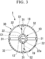
- the stent 1 of the embodiment includes a main body (a major axis member) 10 and an umbrella section (an inflow prevention section) 30.
- An internal space 13 a first opening section 16, and second opening sections 18 and 19 are formed in the main body 10.
- the internal space 13 extends from a front end portion 11 toward a base end portion 12 of the main body 10.
- the first opening section 16 is formed in the front end portion 11 of the main body 10.
- the second opening sections 18 and 19 are formed in an outer circumferential surface (a side surface) 17 of the base end portion 12 of the main body 10.
- the umbrella section 30 has an inflow prevention surface 30a configured to entirely cover the second opening sections 18 and 19.
- the main body 10 is formed of a resin material having elasticity, flexibility and biocompatibility such as urethane, polyethylene, or the like, in a tubular shape.
- the first opening section 16 is installed at a front end surface 15 of the main body 10.
- the first opening section 16 comes in communication with a portion of a front end side of the internal space 13.
- the second opening sections 18 and 19 are formed in a longitudinal axis (a central axis) C1 direction of the main body 10.
- the second opening section 18 is formed closer to the front end than the second opening section 19, and disposed at a position opposite to the second opening section 19 with the longitudinal axis (the central axis) C1 of the main body 10 therebetween.
- the second opening sections 18 and 19 come in communication with a portion of the base end side of the internal space 13.
- a conduit line of the main body 10 is constituted by the above-mentioned internal space 13, the first opening section 16, and an opening 21 formed in a base end surface 12a of the main body 10.
- a valve unit 22 formed in a columnar shape is disposed at the opening 21 of the main body 10.
- the valve unit 22 is formed of a material having elasticity such as rubber or the like.
- a slit 22a passing through the valve unit 22 in a direction (a thickness direction) along the longitudinal axis C1 is formed in the valve unit 22.
- an outer circumferential surface of the valve unit 22 and an inner circumferential surface of the opening 21 are sealed by a known adhesive agent or the like having biocompatibility.
- the slit 22a is closed by an elastic force of the material that forms the valve unit 22 in a natural state in which an external force except for gravity is not applied. Meanwhile, as the slit 22a is elastically deformed against the elastic force, the slit 22a can be opened. Here, an open space of the slit 22a is in communication with the internal space 13.
- the slit 22a in the natural state is closed to prevent introduction of food residue into the internal space 13 through the slit 22a as described below.
- the inflow prevention surface 30a of the umbrella section 30 is an outer surface of the umbrella section 30.
- the inflow prevention surface 30a has a first edge section 30b fixed to the outer circumferential surface 17 of the main body 10 closer to the base end side than the second opening sections 18 and 19.
- a second edge section 30c of the inflow prevention surface 30a is disposed at a position closer to the front end side than the second opening sections 18 and 19 and extends from the outer circumferential surface 17 of the main body 10 toward a position spaced apart outward in a radial direction.
- the umbrella section 30 is formed throughout the entire circumference of the main body 10.
- the umbrella section 30 has a bony portion 31 and a membranous portion 32.
- the bony portion 31 is formed of a material having elasticity.
- the bony portion 31 may be formed of a resin material having elasticity and biocompatibility such as urethane, polyethylene, or the like.
- Four bony portions 31 having first end sections 31a fixed closer to the base end side than the second opening sections 18 and 19 are formed in a circumferential direction of the main body 10.
- the membranous portion 32 extends toward the front end side while closing between the bony portions 31 neighboring in the circumferential direction.
- the bony portions 31 are formed to be spaced apart outward in a radial direction from the outer circumferential surface 17 of the main body 10, while second end sections 31b extend toward the front end side in a natural state.
- the four bony portions 31 are spaced apart from each other in the circumferential direction and disposed at equal angles around the longitudinal axis C1 of the main body 10.
- a fluorine-based resin material having a smooth surface and biocompatibility such as polytetrafluoroethylene (PTFE), perfluoroalkoxyalkane (PFA), or the like, may be appropriately used in the membranous portion 32.
- PTFE polytetrafluoroethylene
- PFA perfluoroalkoxyalkane
- the membranous portion 32 is formed to be more flexible (to have lower stiffness) than the bony portion 31.
- the inflow prevention surface 30a is constituted by outer surfaces of the bony portions 31 and outer surfaces of the membranous portions 32.
- the umbrella section 30 is opened in an umbrella shape in a natural state.
- the inflow prevention surface 30a of the umbrella section 30 is formed to cover the entire second opening section 18 while being spaced by a gap S1 from the second opening section 18 outward in the radial direction of the main body 10.
- the gap S1 is also provided between the second opening section 18 and an inner surface 30d of the umbrella section 30 disposed at the second opening section 18 side.
- the inflow prevention surface 30a is formed to cover the entire second opening section 19 while being spaced by a gap S2 from the second opening section 19 outward in the radial direction.
- the gap S2 is also formed between the inner surface 30d of the umbrella section 30 and the second opening section 19.
- the gaps S1 and S2 are sealed by the first edge section 30b of the inflow prevention surface 30a and the main body 10 at the base end side.
- the flap 40 includes a first flap end section 41 and a second flap end section 42.
- the first flap end section 41 is fixed to the front end portion 11 of the main body 10.
- the second flap end section 42 extends toward a central section 14 of the main body 10 along the longitudinal axis C1, and is formed to be gradually spaced apart from the outer circumferential surface 17 of the main body 10 outward in the radial direction.
- the flap 40 is formed of the same material as the main body 10, and the first end section 41 thereof is fixed to the main body 10 by thermal welding, adhesion, or the like.
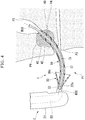
- a user such as an operator inserts a lateral vision type endoscope into a body of a patient from a natural opening such as a mouth or the like, and as shown in Fig. 4 , a front end of an insertion section E1 of an endoscope E is inserted into a duodenum P1 to advance to the vicinity of a duodenal papilla P2.
- a user inserts a guide catheter (a rod-shaped member) W10 into a channel E2 of the endoscope E from a forceps port (not shown) of the endoscope E.
- An outer diameter of the guide catheter W10 is selected to be slightly smaller than an inner diameter of the main body 10 of the stent 1.
- a front end of the guide catheter W10 protrudes from a front end opening of the channel E2 toward the duodenal papilla P2 while appropriately manipulating a sitting-up table (not shown) of the endoscope E. Then, the front end of the guide catheter W10 is inserted into a bile duct P3 from the duodenal papilla P2.
- the user checks a shape of a narrow portion P4 between the duodenal papilla P2 and the bile duct P3 through X-ray illumination, and selects the stent 1 having a length such that a length from the second edge section 30c of the umbrella section 30 when opened to the second end section 42 of the flap 40 is substantially equal to a distance from the duodenal papilla P2 to passing the narrow portion P4 of the bile duct P3.
- valve unit 22 In the outside of the body of the patient, the valve unit 22 is elastically deformed such that the slit 22a of the valve unit 22 of the stent 1 is opened. A base end side of the guide catheter W10 is inserted through the internal space 13 and the deformed slit 22a.
- a pusher catheter (a tubular member) W20 is fitted onto a portion of the guide catheter W10 disposed closer to the base end side than the main body 10.
- the pusher catheter W20 is selected to have an outer diameter and an inner diameter that are substantially equal to an outer diameter and an inner diameter of the main body 10.
- the umbrella section 30 is pressed against the elastic force of the bony portion 31 toward the longitudinal axis C1 throughout the entire circumference, and the bony portion 31 or the membranous portion 32 are deformed at the longitudinal axis C1 side.
- the membranous portion 32 is folded in the circumferential direction, and the umbrella section 30 is closed.
- the pusher catheter W20 is moved toward (pushed into) the front end side with respect to the guide catheter W10 and the stent 1 is inserted into the channel E2 of the endoscope E from the forceps port.
- the flaps 40 pushed against the inner circumferential surface of the channel E2 are deformed toward the longitudinal axis C1 to be closed. That is, the flaps 40 opened outside in the radial direction and the umbrella section 30 opened in an umbrella shape in a natural state are introduced into the channel E2 in a state in which they are closed with small outer diameters.
- the flaps 40 protrude from the front end opening of the channel E2 when the pusher catheter W20 is pushed, the flaps 40 are opened outward in the radial direction by the elastic force thereof.
- the flaps 40 of the stent 1 are inserted into the narrow portion P4 of the bile duct P3 through the channel E2, the flaps 40 are pushed against the inner circumferential surface of the narrow portion P4 are deformed toward the longitudinal axis C 1.
- the second edge section 30c of the umbrella section 30 is also hooked at the duodenal papilla P2. Accordingly, the umbrella section 30 protrudes from the duodenal papilla P2 into a lumen of the duodenum P1.
- the guide catheter W10 is moved (returned) toward the base end with respect to the pusher catheter W20 to draw the guide catheter W10 from the main body 10 while holding the position of the pusher catheter W20.
- the valve unit 22 is elastically deformed and the slit 22a is closed.
- the second edge section 30c of the umbrella section 30 comes in contact with the duodenal papilla P2 at a portion thereof around the longitudinal axis C1, and does not come in contact with the entire circumference. Accordingly, a crevice S4 is formed between a portion in the circumferential direction of the second edge section 30c of the umbrella section 30 and the duodenal papilla P2. That is, the stent 1 is implanted into the bile duct P3 in a state in which the crevice S4 is formed such that food residue is not introduced between the portion in the circumferential direction of the second edge section 30c of the umbrella section 30 and the duodenal papilla P2.
- the guide catheter W10 and the pusher catheter W20 are drawn to the outside through the channel E2 of the endoscope E to draw the insertion section E1 of the endoscope E from the mouth of the patient.
- the bile flowing to the outside from the second opening sections 18 and 19 does not simply flow to the outside in the radial direction but flows outward in the radial direction through the crevice S4 after the bile is blocked by the umbrella section 30 and flows toward the front end once. That is, the bile flowing to the outside of the main body 10 from the second opening sections 18 and 19 flows in an S shape as a whole when seen in a side view to arrive at the outside of the umbrella section 30.
- the umbrella section 30 is formed throughout the entire circumference of the main body 10, regardless of an orientation in the circumferential direction of the stent 1 implanted into the bile duct P3, it is prevented that the food residue flowing as shown by the arrow F5 is introduced into the internal space 13 of the main body 10 from the second opening sections 18 and 19.
- the second opening sections 18 and 19 are formed in the outer circumferential surface 17 of the base end portion 12 of the main body 10, and the inflow prevention surface 30a of the umbrella section 30 is formed to be spaced apart by the gaps S1 and S2 from the second opening sections 18 and 19 outward in the radial direction of the main body 10.
- the food residue flowing through the duodenum P1 varies a direction of a flow abutting the inflow prevention surface 30a and flows from the duodenum P1 toward the small intestine.
- the bile can be easily discharged to the outside at the same degree as the stent of the related art formed in a tubular shape.
- the umbrella section 30 has the bony portion 31 and the membranous portion 32.
- the umbrella section 30 is opened outside in the radial direction by the elastic force of the bony portion 31, and the umbrella section 30 can be hooked by the duodenal papilla P2. Since the umbrella section 30 is introduced into the body of the patient in a state in which the umbrella section 30 is closed with a small outer diameter, a burden applied to the patient upon insertion of the stent 1 can be reduced.
- the entire umbrella section 30 can be flexibly formed while maintaining the elastic force for opening as an umbrella shape in a natural state. Since the umbrella section 30 has the bony portions 31, an open shape of the umbrella section 30 in the natural state can be easily held.
- the umbrella section 30 is formed throughout the entire circumference of the main body 10, regardless of an orientation in the circumferential direction of the stent 1 implanted into the bile duct P3, it is possible to prevent that the food residue is introduced into the internal space 13 of the main body 10 from the second opening sections 18 and 19.
- the valve unit 22 having the slit 22a is installed at the base end portion 12 of the main body 10. Since the slit 22a in the natural state is closed, it is possible to prevent that the food residue is introduced into the internal space 13 from the outside through the slit 22a.
- the stent 1 of the embodiment can be implanted into the bile duct P3 using the general guide catheter W10 and pusher catheter W20 used in the implantation of the stent of the related art.
- the stent 1 configured to prevent a backward flow of the food residue can be implanted into the bile duct P3 using the guide catheter W10 and the pusher catheter W20 of the related art.
- the configuration of the stent 1 according to the embodiment may be variously modified as described below.
- FIG. 7 A variation of the stent according to the embodiment is shown in Fig. 7 .
- the umbrella section 30 having a plurality of bony portions 31 and membranous portions 32 formed between the neighboring bony portions 31 is formed such that the entire circumference of the major axis member 10 is covered by the membranous portions 32 and the bony portions 31.
- a cutout 32a extending from a front end toward a base end may be formed at one of the membranous portions 32.
- the cutout 32a passes through the membranous portion 32 in a thickness direction of the membranous portion 32.
- the stent 1A is disposed such that the cutout 32a is positioned at a downstream (the small intestine) side when the second edge section 30c of the umbrella section 30 is hooked by the duodenal papilla P2.
- the cutout 32a is formed at the membranous portion 32 at a portion of the umbrella section 30, when the second edge section 30c of the umbrella section 30 is hooked by the duodenal papilla P2, the bile is discharged to the outside of the umbrella section 30 through the cutout 32a. Accordingly, the bile can be more securely discharged to the outside of the umbrella section 30.
- an umbrella section 50 may be formed at substantially half of the circumference of the main body 10.
- the umbrella section 50 is not constituted by the bony portions 31 and the membranous portions 32 having different stiffness like the umbrella section 30 of the embodiment.
- the umbrella section 50 is configured by forming a sheet shape thicker than the above-mentioned membranous portion 32, using a fluorine-based resin material.
- the outer diameter can be deformed to be smaller when pushed toward the longitudinal axis C1 from the outside in a radial direction.
- the outer surface of the umbrella section 50 constitutes an inflow prevention surface 50a.
- the gap S1 between the second opening section 18 and the umbrella section 50 comes in communication with the outside of the main body 10 in the circumferential direction of the main body 10.
- the umbrella section 50 may be implanted to be disposed at an upstream (the stomach) side.
- the food residue flowing from the stomach (not shown) abuts the inflow prevention surface 50a of the umbrella section 50 to be directed toward a downstream side.
- bile discharged to the outside of the main body 10 from the second opening section 18 abuts the umbrella section 50 to be directed toward the front end, and thus, flows in an S shape when seen in a side view.
- a stent 1C of a variation may be configured as shown in Fig. 10 .
- the gap S1 between the second opening section 18 and the umbrella section 50 is configured to be blocked by the umbrella section 50 without communication with the outside of the main body 10 in the circumferential direction of the main body 10.
- the umbrella section 50 can be configured in a compact size.
- a sealing member 55 formed of a material having elasticity such as sponge or the like may be provided instead of the valve unit 22 of the stent 1 according to the embodiment.
- the slit 22a like the above-mentioned valve unit 22 is not previously formed at the sealing member 55.
- the sealing member 55 partitions the internal space 13 and the outside of the main body 10.
- the base end side of the guide catheter W10 can be inserted through the internal space 13.
- a through-hole 55a is formed in the sealing member 55 by a method of pushing the guide catheter W10 against the sealing member 55 to break the sealing member 55 or the like.
- the guide catheter W10 is inserted through the formed through-hole 55a.
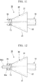
- a stent 2 includes a main body 60 formed in a tubular shape, and an umbrella section 70.
- a notch section 61 is formed at a base end of the main body 60.
- the umbrella section 70 is formed at the base end of the main body 60.
- the main body 60 has the notch section 61 cutout to be inclined from the base end surface of the main body 60 throughout a side surface of a front end side, instead of the second opening sections 18 and 19 of the main body 10 of the first embodiment.
- An opening by the notch section 61 is opened in an inclined direction at the base end side of the stent 2.
- the main body 60 may be formed of the same material as the main body 10.
- the umbrella section 70 is formed of the same material as the umbrella section 50 of the stent 1C shown in Fig. 10 in a side surface shape of a cone with the same thickness.
- the umbrella section 70 has a bottom section 70b formed by closing a base end portion (an umbrella base end portion) 72, and is formed to be spaced apart from the outer circumferential surface of the main body 60 outward in the radial direction while extending toward the front end throughout the entire circumference of the main body 60. That is, the umbrella section 70 is formed in a substantially conical shape having a diameter increasing from the base end to the front end of the main body 60.
- the umbrella section 70 may be formed of a metal mesh as long as the mesh is fine such that food residue cannot pass therethrough.
- the base end portion of the main body 60 and the inner surface of the umbrella section 70 are fixed to each other by an adhesive agent or the like in a state in which a longitudinal axis (a central axis) C2 of the main body 60 and a longitudinal axis of the umbrella section 70 coincide with each other.
- the umbrella section 70 when seen in a direction of a longitudinal axis C2 of the umbrella section 70, the main body 60 and a region 73 that is a portion overlapping the main body 60 correspond to a major axis member 81, a region of the umbrella section 70 except for the region 73 corresponds to an inflow prevention section 74. That is, the umbrella section 70 is constituted by the region 73 serving as the base end portion of the major axis member 81 and the inflow prevention section 74.
- the base end surface of the major axis member 81 is a bottom section of the region 73 of the umbrella section 70. Accordingly, an opening is not formed in the base end surface of the major axis member 81 serving as the region 73 of the umbrella section 70.
- a second opening section 82 formed in a side surface of a base end portion of the major axis member 81 and in communication with an internal space 62 of the main body 60 is constituted by the notch section 61 and the region 73 of the umbrella section 70.
- bile discharged to the outside of the main body 60 from the second opening section 82 collides with the umbrella section 70 spaced apart by a gap S6 from the second opening section 82 outward in the radial direction of the main body 60 to flow toward the front end.
- the stent 2 of the embodiment it is possible to prevent that the food residue is introduced from the second opening section 82 and flows backward to the bile duct P3 through the internal space 62 of the main body 60.
- the umbrella section 70 is constituted by integrally forming the region 73 and the inflow prevention section 74, the base end portion of the major axis member 81 can be securely closed.
- a stent 3 includes a main body 90 formed in a tubular shape, the above-mentioned umbrella section 70, and an joint member 100.
- the joint member 100 connects the main body 90 and the umbrella section 70 and is formed between the main body 90 and the umbrella section 70.
- the main body 90 may be formed of the same material as the main body 10 of the above-mentioned first embodiment or second embodiment.
- the joint member 100 is formed in a rod shape extending in a direction along a longitudinal axis (a central axis) C3 of the main body 90.
- the joint member 100 is formed of stainless steel or a rigid resin material.
- the joint member 100 is adhered to the main body 90 to extend from a wall section 91 of the main body 90 toward a base end.
- the main body 90 and the joint member 100, and the joint member 100 and the umbrella section 70 may be adhered by a known adhesive agent or the like.
- a major axis member 111 is constituted by the main body 90, the joint member 100, and the region 73 of the umbrella section 70.
- the main body 90 corresponds to a front end portion of the major axis member 111
- the region 73 corresponds to a base end portion of the major axis member 111.
- a second opening section 112 is disposed between the main body 90 and the region 73 of the umbrella section 70, and formed at a portion except for the joint member 100.
- the bile flowed to the outside of the main body 90 from the second opening section 112 collides with the umbrella section 70 spaced by a gap S8 from the second opening section 112 outward in the radial direction of the main body 90, and then, flows toward the front end.
- the stent 3 of the embodiment it is possible to prevent that the food residue is introduced from the second opening section 112 and a backward flow to the bile duct P3 through an internal space 92 of the main body 90.
- a cross-sectional shape by a surface perpendicular to the longitudinal axis of the main body may be formed in a contour having an oval shape or a polygonal shape such as a hexagonal shape or the like, in addition to a circular shape.
- the main body may be constituted by a plurality of layers disposed to be concentric with the main body.
- an outer layer disposed at the outer circumferential surface side of the main body formed in the tubular shape may be formed of a resin material having elasticity, flexibility and biocompatibility such as urethane, polyethylene, or the like.
- an inner layer disposed at the inner circumferential surface side of the main body formed in the tubular shape may be formed of a resin material such as PTFE, PFA, or the like.
- the configuration in which the four bony portions 31 that constitute the umbrella section 30 are disposed at intervals of equal angle around the longitudinal axis C1 has been shown.
- the bony portions 31 may not be disposed at intervals of equal angle around the longitudinal axis C1.
- the configuration in which the number of bony portions 31 that constitute the umbrella section 30 is four has been shown.
- the number of bony portions 31 that constitute the umbrella section 30 is not limited thereto but may be 1 to 3 and 5 or more.
- the inflow prevention surface may be formed to cover the second opening section within a range in which the food residue or the like can be prevented from being introduced into the stent via the second opening section in a state in which the stent is implanted in the target area.
- the membranous portion may be formed between a set of neighboring bony portions, and in the circumferential direction of the main body, the inflow prevention surface configured to cover the second opening section throughout a half circumference may be formed.
- the configuration in which the four flaps 40 are fixed to the front end portion 11 of the main body 10 has been shown.
- the flaps 40 may not be provided at the stent.
- lumen tissue into which the stent is implanted was the bile duct P3.
- the lumen tissue is not limited to the bile duct P3 but may be, for example, a pancreatic duct or the like.
- a stent capable of suppressing introduction of a fluid such as a food residue or the like from the second opening section and a backward flow through the internal space of the main body can be provided.
Landscapes
- Health & Medical Sciences (AREA)
- Engineering & Computer Science (AREA)
- Biomedical Technology (AREA)
- Animal Behavior & Ethology (AREA)
- Veterinary Medicine (AREA)
- Public Health (AREA)
- Heart & Thoracic Surgery (AREA)
- General Health & Medical Sciences (AREA)
- Life Sciences & Earth Sciences (AREA)
- Transplantation (AREA)
- Vascular Medicine (AREA)
- Oral & Maxillofacial Surgery (AREA)
- Cardiology (AREA)
- Urology & Nephrology (AREA)
- Ophthalmology & Optometry (AREA)
- Otolaryngology (AREA)
- Anesthesiology (AREA)
- Hematology (AREA)
- Gastroenterology & Hepatology (AREA)
- Pulmonology (AREA)
- Media Introduction/Drainage Providing Device (AREA)
- Prostheses (AREA)
Applications Claiming Priority (2)
| Application Number | Priority Date | Filing Date | Title |
|---|---|---|---|
| US201361845035P | 2013-07-11 | 2013-07-11 | |
| PCT/JP2014/065073 WO2015005036A1 (fr) | 2013-07-11 | 2014-06-06 | Endoprothèse |
Publications (2)
| Publication Number | Publication Date |
|---|---|
| EP3020376A1 true EP3020376A1 (fr) | 2016-05-18 |
| EP3020376A4 EP3020376A4 (fr) | 2017-01-11 |
Family
ID=52279727
Family Applications (1)
| Application Number | Title | Priority Date | Filing Date |
|---|---|---|---|
| EP14823751.4A Withdrawn EP3020376A4 (fr) | 2013-07-11 | 2014-06-06 | Endoprothèse |
Country Status (5)
| Country | Link |
|---|---|
| US (1) | US9585742B2 (fr) |
| EP (1) | EP3020376A4 (fr) |
| JP (1) | JP5885882B2 (fr) |
| CN (1) | CN105358101B (fr) |
| WO (1) | WO2015005036A1 (fr) |
Families Citing this family (8)
| Publication number | Priority date | Publication date | Assignee | Title |
|---|---|---|---|---|
| US10226606B2 (en) * | 2014-04-10 | 2019-03-12 | C.R. Bard, Inc. | Ureteral stents |
| US20180126129A1 (en) * | 2014-07-21 | 2018-05-10 | Stentorium Ltd | Implantable Stent |
| US10624733B2 (en) * | 2015-03-24 | 2020-04-21 | Spiration, Inc. | Airway stent |
| WO2018157206A1 (fr) * | 2017-02-28 | 2018-09-07 | Alexander Koefman | Insert médical |
| US11344401B2 (en) * | 2017-06-13 | 2022-05-31 | Kaneka Corporation | In-vivo indwelling tube |
| USD952854S1 (en) | 2019-02-28 | 2022-05-24 | Olympus Corporation | Stent |
| JP7534734B2 (ja) * | 2020-05-28 | 2024-08-15 | 日本ゼオン株式会社 | チューブステント |
| US20220226096A1 (en) * | 2021-01-15 | 2022-07-21 | Boston Scientific Scimed, Inc. | Covered Endoprosthesis with Improved Branch Drainage |
Family Cites Families (17)
| Publication number | Priority date | Publication date | Assignee | Title |
|---|---|---|---|---|
| JPS60180442U (ja) * | 1984-05-09 | 1985-11-30 | オリンパス光学工業株式会社 | 留置型プロステ−セス |
| ATE120354T1 (de) | 1990-07-09 | 1995-04-15 | Wilson Cook Medical Inc | Vorrichtung zum herausziehen von rekanalisierungsrohren. |
| US6746489B2 (en) * | 1998-08-31 | 2004-06-08 | Wilson-Cook Medical Incorporated | Prosthesis having a sleeve valve |
| ATE322230T1 (de) * | 1998-09-10 | 2006-04-15 | Percardia Inc | Tmr vorrichtung |
| US7615076B2 (en) * | 1999-10-20 | 2009-11-10 | Anulex Technologies, Inc. | Method and apparatus for the treatment of the intervertebral disc annulus |
| US6921378B2 (en) * | 2001-10-09 | 2005-07-26 | Boston Scientific Scimed, Inc. | Anti-reflux drainage devices and methods |
| DE602004023350D1 (de) * | 2003-04-30 | 2009-11-12 | Medtronic Vascular Inc | Perkutaneingesetzte provisorische Klappe |
| US20050149166A1 (en) * | 2003-11-08 | 2005-07-07 | Schaeffer Darin G. | Branch vessel prosthesis with anchoring device and method |
| US7470247B2 (en) * | 2004-04-26 | 2008-12-30 | Gyrus Acmi, Inc. | Ureteral stent |
| JP4901087B2 (ja) * | 2004-09-24 | 2012-03-21 | オリンパス株式会社 | ステント導入部材、ステントデリバリーカテーテル、及び内視鏡処置システム |
| GB0700560D0 (en) * | 2007-01-11 | 2007-02-21 | Emcision Ltd | Device and method for the treatment of diseased tissue such as tumours |
| US8221505B2 (en) * | 2007-02-22 | 2012-07-17 | Cook Medical Technologies Llc | Prosthesis having a sleeve valve |
| AU2008293471B2 (en) * | 2007-08-31 | 2013-10-24 | Cook Medical Technologies Llc | Medical implant having improved drug eluting features |
| CN102202605A (zh) * | 2008-10-22 | 2011-09-28 | 威尔逊-库克医学公司 | 预防胰腺病症的支架 |
| US20120316632A1 (en) * | 2011-06-13 | 2012-12-13 | Bulang Gao | Retrievable covered stent for bifurcation aneurysms |
| EP2609892B1 (fr) * | 2011-12-28 | 2018-08-08 | Cook Medical Technologies LLC | Stent urétéral |
| WO2015102988A1 (fr) * | 2013-12-30 | 2015-07-09 | Stryker Corporation | Endoprothèse et procédé d'utilisation |
-
2014
- 2014-06-06 CN CN201480038827.XA patent/CN105358101B/zh active Active
- 2014-06-06 EP EP14823751.4A patent/EP3020376A4/fr not_active Withdrawn
- 2014-06-06 JP JP2015501965A patent/JP5885882B2/ja active Active
- 2014-06-06 WO PCT/JP2014/065073 patent/WO2015005036A1/fr not_active Ceased
-
2015
- 2015-12-28 US US14/981,534 patent/US9585742B2/en active Active
Also Published As
| Publication number | Publication date |
|---|---|
| CN105358101A (zh) | 2016-02-24 |
| WO2015005036A1 (fr) | 2015-01-15 |
| US20160128824A1 (en) | 2016-05-12 |
| JP5885882B2 (ja) | 2016-03-16 |
| EP3020376A4 (fr) | 2017-01-11 |
| JPWO2015005036A1 (ja) | 2017-03-02 |
| US9585742B2 (en) | 2017-03-07 |
| CN105358101B (zh) | 2017-10-10 |
Similar Documents
| Publication | Publication Date | Title |
|---|---|---|
| EP3020376A1 (fr) | Endoprothèse | |
| US9320508B2 (en) | Expandable medical access sheath | |
| US20210068992A1 (en) | Bifurcated side-access intravascular stent graft | |
| EP3106135B1 (fr) | Endoprothèse empêchant une inversion de la circulation | |
| WO2018054275A1 (fr) | Gaine de cathéter extensible et dispositif d'administration d'un instrument d'intervention | |
| US10130460B2 (en) | Stent having exterior path | |
| JP7451841B2 (ja) | 管状治療具、管状治療具セット及び管状治療具留置装置 | |
| US20190030304A1 (en) | Foldable urinary catheter | |
| US20120071965A1 (en) | Implantable graft connector | |
| EP2486911B1 (fr) | Tuyau d'alimentation gastro-jejunal à profil bas | |
| CN116456915A (zh) | 支架以及使用和制造具有改进的保持构件的支架的方法 | |
| JP2018134369A (ja) | ステント挿入装置 | |
| JP2015036043A (ja) | チューブステント搬送装置 | |
| KR101604990B1 (ko) | 스텐트 | |
| CN102958472B (zh) | 医用支架 | |
| JP6589337B2 (ja) | ステントデリバリー装置 | |
| KR101753206B1 (ko) | 연결용 스텐트 | |
| US20200016382A1 (en) | Drainage catheter | |
| JP7325744B1 (ja) | カテーテルシステム | |
| JP6904385B2 (ja) | ステントデリバリー装置 | |
| JP7663795B2 (ja) | 管状留置具 | |
| JP7198058B2 (ja) | 医療具の搬送装置 | |
| CN103041494B (zh) | 导管 | |
| WO2020179293A1 (fr) | Système de pose d'endoprothèse | |
| KR20210035398A (ko) | 수술용 파우치 어셈블리 |
Legal Events
| Date | Code | Title | Description |
|---|---|---|---|
| PUAI | Public reference made under article 153(3) epc to a published international application that has entered the european phase |
Free format text: ORIGINAL CODE: 0009012 |
|
| 17P | Request for examination filed |
Effective date: 20160202 |
|
| AK | Designated contracting states |
Kind code of ref document: A1 Designated state(s): AL AT BE BG CH CY CZ DE DK EE ES FI FR GB GR HR HU IE IS IT LI LT LU LV MC MK MT NL NO PL PT RO RS SE SI SK SM TR |
|
| AX | Request for extension of the european patent |
Extension state: BA ME |
|
| RAP1 | Party data changed (applicant data changed or rights of an application transferred) |
Owner name: OLYMPUS CORPORATION |
|
| RAP1 | Party data changed (applicant data changed or rights of an application transferred) |
Owner name: OLYMPUS CORPORATION |
|
| RIN1 | Information on inventor provided before grant (corrected) |
Inventor name: NOMURA, YUSUKE |
|
| DAX | Request for extension of the european patent (deleted) | ||
| A4 | Supplementary search report drawn up and despatched |
Effective date: 20161209 |
|
| RIC1 | Information provided on ipc code assigned before grant |
Ipc: A61F 2/94 20130101AFI20161205BHEP Ipc: A61F 2/04 20130101ALN20161205BHEP |
|
| RAP1 | Party data changed (applicant data changed or rights of an application transferred) |
Owner name: OLYMPUS CORPORATION |
|
| RIN1 | Information on inventor provided before grant (corrected) |
Inventor name: NOMURA, YUSUKE |
|
| STAA | Information on the status of an ep patent application or granted ep patent |
Free format text: STATUS: REQUEST FOR EXAMINATION WAS MADE |
|
| STAA | Information on the status of an ep patent application or granted ep patent |
Free format text: STATUS: THE APPLICATION IS DEEMED TO BE WITHDRAWN |
|
| 18D | Application deemed to be withdrawn |
Effective date: 20210112 |