EP3020660A1 - Dispositif et procede de determination d'un degre d'occupation d'un dispositif de transport - Google Patents
Dispositif et procede de determination d'un degre d'occupation d'un dispositif de transport Download PDFInfo
- Publication number
- EP3020660A1 EP3020660A1 EP15187291.8A EP15187291A EP3020660A1 EP 3020660 A1 EP3020660 A1 EP 3020660A1 EP 15187291 A EP15187291 A EP 15187291A EP 3020660 A1 EP3020660 A1 EP 3020660A1
- Authority
- EP
- European Patent Office
- Prior art keywords
- detection
- transport
- transport device
- determining
- transported
- Prior art date
- Legal status (The legal status is an assumption and is not a legal conclusion. Google has not performed a legal analysis and makes no representation as to the accuracy of the status listed.)
- Granted
Links
Images


Classifications
-
- G—PHYSICS
- G06—COMPUTING OR CALCULATING; COUNTING
- G06M—COUNTING MECHANISMS; COUNTING OF OBJECTS NOT OTHERWISE PROVIDED FOR
- G06M7/00—Counting of objects carried by a conveyor
-
- B—PERFORMING OPERATIONS; TRANSPORTING
- B65—CONVEYING; PACKING; STORING; HANDLING THIN OR FILAMENTARY MATERIAL
- B65G—TRANSPORT OR STORAGE DEVICES, e.g. CONVEYORS FOR LOADING OR TIPPING, SHOP CONVEYOR SYSTEMS OR PNEUMATIC TUBE CONVEYORS
- B65G43/00—Control devices, e.g. for safety, warning or fault-correcting
- B65G43/08—Control devices operated by article or material being fed, conveyed or discharged
-
- B—PERFORMING OPERATIONS; TRANSPORTING
- B65—CONVEYING; PACKING; STORING; HANDLING THIN OR FILAMENTARY MATERIAL
- B65G—TRANSPORT OR STORAGE DEVICES, e.g. CONVEYORS FOR LOADING OR TIPPING, SHOP CONVEYOR SYSTEMS OR PNEUMATIC TUBE CONVEYORS
- B65G15/00—Conveyors having endless load-conveying surfaces, i.e. belts and like continuous members, to which tractive effort is transmitted by means other than endless driving elements of similar configuration
- B65G15/22—Conveyors having endless load-conveying surfaces, i.e. belts and like continuous members, to which tractive effort is transmitted by means other than endless driving elements of similar configuration comprising a series of co-operating units
-
- G—PHYSICS
- G06—COMPUTING OR CALCULATING; COUNTING
- G06M—COUNTING MECHANISMS; COUNTING OF OBJECTS NOT OTHERWISE PROVIDED FOR
- G06M1/00—Design features of general application
- G06M1/02—Housing
-
- B—PERFORMING OPERATIONS; TRANSPORTING
- B65—CONVEYING; PACKING; STORING; HANDLING THIN OR FILAMENTARY MATERIAL
- B65G—TRANSPORT OR STORAGE DEVICES, e.g. CONVEYORS FOR LOADING OR TIPPING, SHOP CONVEYOR SYSTEMS OR PNEUMATIC TUBE CONVEYORS
- B65G2201/00—Indexing codes relating to handling devices, e.g. conveyors, characterised by the type of product or load being conveyed or handled
- B65G2201/02—Articles
- B65G2201/0235—Containers
- B65G2201/0244—Bottles
-
- B—PERFORMING OPERATIONS; TRANSPORTING
- B65—CONVEYING; PACKING; STORING; HANDLING THIN OR FILAMENTARY MATERIAL
- B65G—TRANSPORT OR STORAGE DEVICES, e.g. CONVEYORS FOR LOADING OR TIPPING, SHOP CONVEYOR SYSTEMS OR PNEUMATIC TUBE CONVEYORS
- B65G2203/00—Indexing code relating to control or detection of the articles or the load carriers during conveying
- B65G2203/02—Control or detection
- B65G2203/0208—Control or detection relating to the transported articles
-
- B—PERFORMING OPERATIONS; TRANSPORTING
- B65—CONVEYING; PACKING; STORING; HANDLING THIN OR FILAMENTARY MATERIAL
- B65G—TRANSPORT OR STORAGE DEVICES, e.g. CONVEYORS FOR LOADING OR TIPPING, SHOP CONVEYOR SYSTEMS OR PNEUMATIC TUBE CONVEYORS
- B65G2203/00—Indexing code relating to control or detection of the articles or the load carriers during conveying
- B65G2203/04—Detection means
- B65G2203/042—Sensors
- B65G2203/044—Optical
Definitions
- the present invention relates to an apparatus and a method for determining a degree of occupancy of a transport device, which in particular transports containers in a container treatment plant.
- a plurality of containers can be transported side by side in a transport direction.
- the transport device is fully or even partially occupied by containers. It is advantageous to reduce the speed of downstream devices, such. B. cleaning device, packaging device, etc. depending on the occupancy rate of the transport device to regulate.
- an automatic control and regulation of the container treatment plant can be realized with the least possible use of operating personnel.
- WO 2008/116546 A2 shows a method for monitoring, control and optimization of filling equipment for food, especially for beverage bottles.
- the procedure is used for plant or machine monitoring.
- an optoelectronic recognition system in the form of at least one electronic camera is used in order to obtain the necessary control data.
- the optical Detection systems can be used to monitor the occupancy rate of buffer tables.
- a disadvantage of such optical recognition systems is that the camera systems reach their limits when processing non-cooperative container surfaces. In this case, a stable detection of the occupancy rate is not guaranteed.
- an object of the present invention to provide an apparatus and a method for determining a degree of occupancy of a transport device, with which the aforementioned problems can be solved.
- an apparatus and a method for determining a degree of occupancy of a transport device are to be provided, with which a determination of a degree of occupancy of a transport device can be implemented simply, flexibly and cost-effectively.
- the device comprises an adjusting device for setting at least one detection device such that the at least one detection device detects the transport device without transported transported goods after detecting transported goods transported with the transport device or vice versa, and a determination device for determining a current degree of occupancy of the transport device on the basis of the adjustment set position of the at least one detection device.
- the device comprises only simple, process-stable standard components. Therefore, no expert knowledge or special software for setting the device is required.
- the device does not require smart detectors such as light-section based sensors or camera or laser technology. Thus, the hardware required for the device is reduced.
- the aforementioned device offers a very efficient and cost-effective way of detecting or determining the occupancy rate. This results in only a very low calibration and referencing.
- the device due to their simple design substantially independent of the width of the conveyor belt to be detected.
- the setting device is also possible for setting at least two detection devices such that a detection device of the detection devices detects transported goods transported by the transport device and the other detection device of the detection devices detects the transport device without transported transported goods, and wherein the determination device determines the current occupancy rate of the transport device Transport device determined on the basis of the set by the setting position of at least one of the detection devices.
- the at least two detection devices are designed to detect transversely to the transport plane of the transport device.
- the device also has a support device for supporting the at least one detection device and / or for supporting at least two detection devices such that the at least two detection devices are arranged at a predetermined fixed distance from one another.
- the support device can be designed to arrange the at least one detection device over the transport device.
- the support means may comprise a receiving device for receiving the at least one detection device, which is designed as a carriage or pull rope such that the at least one detection device is linearly movable over the transport device.
- the device also has a position detection device for detecting a position of the at least one detection device and / or a receiving device receiving the at least one detection device on the support device.
- a position detection device for detecting a position of the at least one detection device and / or a receiving device receiving the at least one detection device on the support device.
- the at least one detection device comprises a contactless sensor.
- the device described above may be part of a transport device for transporting containers, wherein the transport device also has a conveyor belt for transporting the containers in a predetermined transport direction.
- the transport device additionally has at least one further conveyor belt, which can be driven independently of the conveyor belt at different speeds to the conveyor belt.
- the object is also achieved by a method for determining a degree of occupancy of a transport device according to claim 10.
- the method comprises the steps of adjusting, with an adjustment device, at least one detection device such that the at least one detection device detects the transport device without transported transported goods after detecting transported goods transported with the transport device, and vice versa, and determining, with a determination device, a current occupancy level the transport device on the Basis of the adjustment of the set position of the at least one detection device.
- the method achieves the same advantages as previously mentioned with respect to the device.
- Fig. 1 shows a machine 1, which may be, for example, a container treatment plant.
- containers 2 in particular transparent plastic bottles, glass bottles, metal cans, empty, full, closed, unsealed, labeled, not labeled, etc., are produced and / or treated.
- the machine 1 is described below partially using the example of a container treatment plant, the machine 1 is not limited thereto.
- Fig. 1 For the sake of simplicity, not all containers 2 are provided with a reference numeral.
- the machine 1 has a first treatment device 10, a transport device 20 and a second treatment device 30.
- the first treatment device 10 is, for example, a labeling device for labeling containers 2 with a label.
- the second treatment device 30 is, for example, a filling device for filling the containers 2 with a medium, such as a liquid, a powder, etc., in particular a beverage, a cleaning agent, etc.
- the transport device 20 transports the containers 2 as transported goods from the first Treatment device 10 to the second treatment device 30th
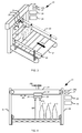
- Fig. 2 shows a part of the transport device 20 in more detail.
- the transport device 20 has a conveyor belt 21 for transporting goods to be transported, such as the container 2, in a transport direction TR.
- the transport device 20 In Fig. 2 is the conveyor belt 21 and thus the transport device 20 only partially occupied by cargo in the form of the container 2.
- the other part of the conveyor belt 21 is free of cargo in the form of containers 2.
- the occupancy rate of the transport device 20 is about 35%. Accordingly, in about 65% of the transport device 20 are not occupied by cargo in the form of container 2.
- a device 23 for determining a degree of occupancy of the transport device 20 is mounted on the transport device 20.
- the device 23 has a support device 24, a receiving unit 241, a drive device 242, a first detection device 25, a second detection device 26, a position detection device 27, an adjustment device 28 and a detection device 29.
- the reception unit 241 is connected to the drive device 242 in a movement direction BR movable.
- the adjusting device 28 is combined with the drive device 242 or controls these.
- a part of the support means 24 is arranged together with the receiving unit 241 and the first and second detection means 25, 26 above the transport means 20. More specifically, the receiving unit 241 and the first and second detecting means 25, 26 are disposed above the conveyor belt 21.
- the support means 24 is configured as a U-shaped frame to which the receiving unit 241 is attached.
- the first and second detection means 25, 26 are accommodated on the receiving unit 241 in such a way that the first and second detection means 25, 26 are spaced from each other by the fixed predetermined distance AB, as in FIG Fig. 4 shown.
- the support means 24 supports the first detection means 25 at the predetermined fixed distance AB to the second detection means 26th
- the receiving unit 241 is movably mounted on the support means 24. Thereby, the receiving unit 241 can be moved together with the first and second detection means 25, 26 as a unit relative to the support means 24 in the direction of the arrow designated BR.
- the arrow thus indicates the direction of movement BR of the receiving unit 241 and the first and second detecting means 25, 26.
- the receiving unit 241 is shown as a carriage on which the first and second detecting means 25, 26 are mounted.
- the carriage can be driven by the drive device 242, which is in particular an electric motor.
- the receiving unit 241 and the detection means 25, 26 are set in a common linear movement via the transport device 20.
- the receiving unit 241 can be reciprocated together with the first and second detecting means 25, 26 via the transporting means 20 in the moving direction BR.
- the first and second detection means 26, 27 can be moved transversely to the transport direction TR relative to the transport means 20.
- the direction of movement BR of the receiving unit 241 and the first and second detection means 25, 26 is arranged transversely, in particular perpendicular, to the transport direction TR of the conveyor belt 21.
- the term "transverse" here comprises an angle between 1 ° and 90 ° to the transport direction TR.
- the device 23 can also be used, for example, on a push-over, at which the containers 2 are forwarded by the conveyor belt 21 to a laterally arranged next conveyor belt 21.
- the device 23 could then be mounted in a different arrangement than at right angles to the transport direction TR.
- the support device 24 is thus designed for the movable supports of the first and second detection means 25, 26, so that the first and second detection means 25, 26 are movable together in a linear manner over the transport means 20.
- the first and second detection means 25, 26 are each in particular non-contact and / or momentary sensors, such as an optical sensor, which operates by means of light, such as infrared light, laser light, etc.
- each of the first and second detection means 25, 26 can also be an acoustic sensor which operates by means of sound waves, preferably ultrasound.
- the first and second detection means 25, 26 can each also be a capacitive sensor.
- the first and second detection means 25, 26 can be configured such that the respective detection means 25, 26 have both a transmitter for transmitting the detection waves and a receiver for receiving the detection waves. As in FIG. 3 and FIG. 4 1, the detection waves are returned to the detectors 25, 26 in the direction of an arrow labeled MS by the conveyor 20 or the cargo.
- first and second detection means 25, 26 are thus designed to detect transversely, in particular vertically, to the transport plane in the form of the conveyor belt 21 of the transport device 20.
- the setting device 28 adjusts the first detection device 25 in such a way that the first detection device 25 detects transported goods transported by the transport device 20, as in FIG Fig. 4 shown. At the in FIG. 3 and FIG. 4 shown position of the first detection means 25 detects the first detection means 25 so the cargo in the form of the container. 2
- the setting device 28 sets the second detection device 26 such that the second detection device 26, the transport device 20 without transported Transport goods recorded, as in FIG. 3 and FIG. 4 shown.
- position of the second detection means 26 detects the second detection means 26 so no cargo in the form of the container 2 but the conveyor belt 21st
- the position of the first and second detection means 25, 26 and / or the recording unit 241 are detected by a position detection means 27 and forwarded to the detection means 29 in the form of one or more detection signals.
- the position detection device 27 may be a rotary encoder, in particular an incremental rotary encoder.
- the determining means 29 determines whether the setting means 28 has set the first and second detecting means 25, 26, as in FIG FIG. 3 and FIG. 4 shown and as previously described. If this is the case, the determination device 29 determines the current occupancy rate of the transport device 20. In this case, the determination device 29 uses the position of the first and second detection devices 25, 26 determined by the position detection device 27 on the transport device 20. In other words, the determination device 29 determines the current one Degree of occupancy of the transport device 20 on the basis of the positions of the first and second detection devices 25, 26 set by the setting device 28.
- the determined occupancy rate can be used to implement efficient control algorithms, such as control of the machine 1, rapid product change and / or asymmetrical dynamic distribution of container flows.
- the device 23 does not perform a direct measurement of the occupancy rate by, for example, opto-electronic sensors. Instead, the detectors 25, 26 function as aids to indirect measurement requiring less effort, such as hardware, software, calibration, and so on.
- the first detection device 25 is thus set in one step with the setting device 28 such that the first detection device 25 detects transport goods transported with the transport device 20.
- the setting device 28 adjusts the second detection device 26 such that the second detection device 26 detects the transport device 20 without transported goods to be transported.
- the determining means 29 determines the current occupancy rate of the transporting means 20 based on the position of the first and second detecting means 25, 26 set by the setting means 28.
- the setting device 28 can also set the second detection device 26 in such a way that the second detection device 26 detects transported goods transported by the transport device 20.
- the setting device 28 adjusts the first detection device 25 in such a way that the first detection device 25 detects the transport device 20 without transported goods to be transported.
- the setting device 28 adjusts the detection devices 25, 26 such that one of the detection devices 25, 26 detects transported goods transported by the transport device 20 and the other of the detection devices 25, 26 detects the transport device 20 without transported goods to be transported.
- the method described above for determining the degree of occupancy is preceded by an initial referencing of the device 23.
- the referencing can take place, for example, via a linear method of the at least one detection device 25, 26 and / or the recording device 241 from a defined start position, for example 0% or 100% degree of occupancy of the transport device 20 over the entire width of the device.
- a sensor preferably by means of a limit switch, the achievement of the maximum possible travel of the detection devices and / or the receiving device is detected and this position then - depending on the starting position - defined as 0% or 100%.
- the detection means 25, 26 For detecting a degree of occupancy of 0% or 100%, in which one of the detection means 25, 26 is arranged at the 0% or 100% position on the transport device 20, the detection means 25, 26 need not necessarily have a limit switch.
- the detection devices 25, 26 may also be configured to detect the railing 22. Here, it is used that the railing 22 is higher than the conveyor belt 21, to which the detection means 25, 26 are referenced prior to their operation. As an additional security, however, not shown limit switch can be installed so that z. B. the drive means 242 with the method of the receiving device 241 stops when the maximum travel distance in the direction of movement BR on the support means 24 and over the transport means 20 is reached.
- the detection means 25, 26 and / or the receiving device 241 is moved so long with linear conveyor belt 21 from its starting position from / to, until It is recognized that the at least one detection device 25, 26 no longer detects the conveyor belt 21 but, for example, a railing 22.
- 22 reflectors are applied to the top of the mutual railing and the at least one detection device 25, 26 is moved from the starting position until it detects a first reflector and thus the associated railing 22. Subsequently, a direction reversal of the considered detection device 25 and / or 26 until a second reflector strip is detected. On the basis of the travel paths can then be closed to the 0% or 100% position of the considered detection device 25 and / or 26.
- the mentioned possibilities for referencing can be performed manually, for example via a software command or a mechanical switch, and / or automatically.
- the device 23 forms a system comprising two simple probing sensors, the detectors 25, 26.
- the sensors can be moved linearly together and mounted at a defined distance AB from one another, in particular vertically, above the conveyor belt 21.
- the receiving unit 241 as a linear axis is in this case in particular motor-adjustable and the position of the mounted sensors above the conveyor belt 21 can be measured.
- the sensors are now always brought into a position that one of them detects the container flow formed from the containers 2 as a transported material and the other sensor remains free.
- Upon detection of a different state is defined by the adjusting device 28 as long as night until the desired state is reached again.
- By evaluating the sensor position can be deduced the current occupancy rate of the conveyor belt 21 and thus the transport device 20.
- the device 23 provides a simple and less prone to interference way to determine the occupancy rate of the transport device 20 or measure. The used
- Detection devices 25, 26 need only be able to roughly recognize whether or not a container flow is present on the region of the transport device 20 detected by the respective detection device 25, 26. This corresponds to a digital detection with 0 and 1 and is not an accurate measurement, for example, in terms of light transit times, brightness, sonic wave transit times, etc ..
- the receiving device 241, to which the detection means 25, 26 are fixed moves, as long as transversely, in particular perpendicular to Transport direction TR of the transport device 20 or in particular parallel to the transport plane formed by the conveyor belt 21 until one of the detection means 25, 26 detects the container flow and the other of the detection means 25, 26 is "free". The position of the receiving device 241 upon entry of this state can then be converted into the occupancy rate of the transport device 20.
- Fig. 5 shows a device 230 on a transport device 20 according to a second embodiment.
- the receiving unit 241 on a traction unit 243, such as a pull rope arranged, which moves the receiving unit 241 and thus the first and second detection means 25, 26 by pulling around deflection shafts 244 in a common linear movement over the transport means 20.
- At least one of the deflection shafts 244 can be driven by a drive device 242, in particular an electric motor.
- the engine 1 according to the second embodiment is executed in the same manner as in the previous embodiment.
- Fig. 6 shows a device 231 on a transport device 20 according to a third embodiment.
- the first detection means 25 is arranged as a single detection means on the receiving unit 241.
- the device 231 is constructed in the same way as the device 23 according to the first embodiment.
- the device 231 Since only one detection device, namely the first detection device 25, is thus present for determining the degree of occupancy of the transport device 20, the device 231 according to the present exemplary embodiment carries out the method described below.
- the detection device 25 moves from the position which corresponds to an occupancy level of the transport device 20 of 0%, until the detection device 25 no longer detects or "sees" container 2. With complete occupancy of the transport device 20 with containers 2, the detection device 25 moves to the position corresponding to a degree of occupancy of the transport device 20 of 100%.
- the two positions can also be referred to as 0% position and 100% position. At the 0% position and the 100% position, the detection device 25 respectively captures the transport device 20 without transported goods to be transported, namely, for example, the railing 22 of the transport device 20.
- the device 231 performs the same procedures as the device 23 according to the first embodiment.
- two receiving devices 241, each with two detection devices 25, 26 are used.
- the two receiving devices 241 can then either be moved at a fixed distance from one another, ie be controllable, or independently of one another.
- Such an arrangement has the advantage that the dimensions of a container stream, which is transported centrally on the conveyor belt 21 of the transport device 20, can be detected from two sides.
- the degree of occupancy of the transport device 20 can also be determined in this way.
- each detection means 25, 26 a separate receptacle 241 may be present.
- the two receiving devices 241 can either be coupled to the respective detection device 25, 26, as a result of which they are moved at a fixed distance from one another, ie can be controlled, or are each driven separately by a drive device 242.
- the control effort for controlling the detection devices 25, 26 is higher here than in the previously described embodiments with two detection devices 25, 26.
- the transport device 20 may have at least one further conveyor belt which can be driven independently of the conveyor belt 21 at different speeds to the conveyor belt 21.
- One of the detection devices 25, 26 can also be embodied as an optical sensor and the other as an acoustic sensor. Furthermore, a combination of all sensor types mentioned in the description of the invention is conceivable.
- the two detecting means 25, 26 may also be more than the two detecting means 25, 26 as long as one of them is set by the setting means 28 for detecting the conveyed goods and the other one for detecting the conveying belt 21.
- one of the detection devices 25, 26, which was previously set to detect the conveyor belt 21, is also possible for one of the detection devices 25, 26, which was previously set to detect the conveyor belt 21, to be subsequently set for detecting the transported goods, and vice versa.
- the adjusting device 28 and the determining device 29 may be embodied by a control device of the machine 1 or a control device of the transport device 20.
- the adjusting device 28 and the determining device 29 may be combined in a device, for example a computer, in particular as a control device of the machine 1. It is also possible that the adjusting device 28 is executed by a control device of the transport device 20 and the determining device 29 by a control device of the machine 1.
Landscapes
- Engineering & Computer Science (AREA)
- Physics & Mathematics (AREA)
- General Physics & Mathematics (AREA)
- Theoretical Computer Science (AREA)
- Mechanical Engineering (AREA)
- Control Of Conveyors (AREA)
Applications Claiming Priority (1)
| Application Number | Priority Date | Filing Date | Title |
|---|---|---|---|
| DE102014116516.0A DE102014116516A1 (de) | 2014-11-12 | 2014-11-12 | Vorrichtung und Verfahren zur Ermittlung eines Belegungsgrads einer Transporteinrichtung |
Publications (2)
| Publication Number | Publication Date |
|---|---|
| EP3020660A1 true EP3020660A1 (fr) | 2016-05-18 |
| EP3020660B1 EP3020660B1 (fr) | 2019-10-23 |
Family
ID=54292570
Family Applications (1)
| Application Number | Title | Priority Date | Filing Date |
|---|---|---|---|
| EP15187291.8A Active EP3020660B1 (fr) | 2014-11-12 | 2015-09-29 | Dispositif et procede de determination d'un degre d'occupation d'un dispositif de transport |
Country Status (4)
| Country | Link |
|---|---|
| US (1) | US9582752B2 (fr) |
| EP (1) | EP3020660B1 (fr) |
| CN (1) | CN105584808B (fr) |
| DE (1) | DE102014116516A1 (fr) |
Cited By (1)
| Publication number | Priority date | Publication date | Assignee | Title |
|---|---|---|---|---|
| EP3293592A1 (fr) * | 2016-06-17 | 2018-03-14 | Deutsche Post AG | Controle de convoyeurs |
Families Citing this family (3)
| Publication number | Priority date | Publication date | Assignee | Title |
|---|---|---|---|---|
| DE102021121123A1 (de) | 2021-08-13 | 2023-02-16 | Krones Aktiengesellschaft | Transporteinrichtung und Transportverfahren für Behälterbehandlungsanlage |
| DE102022117311A1 (de) * | 2022-07-12 | 2024-01-18 | Krones Aktiengesellschaft | Verfahren zum Ermitteln einer Belegungssituation von Behältern in einer Anlage und Vorrichtung dazu |
| DE102023133635A1 (de) * | 2023-12-01 | 2025-06-05 | Krones Aktiengesellschaft | Vorrichtung und Verfahren zum Aufteilen eines Behältermassenstroms |
Citations (11)
| Publication number | Priority date | Publication date | Assignee | Title |
|---|---|---|---|---|
| GB795525A (en) * | 1954-09-24 | 1958-05-28 | British Iron Steel Research | Improvements in or relating to indicating and/or measuring instruments |
| FR2213481A1 (fr) * | 1973-01-10 | 1974-08-02 | Nippon Kokan Kk | |
| DE2631436A1 (de) * | 1976-07-13 | 1978-01-19 | Leuze Electronic Kg | Anordnung zum erfassen von bewegten gegenstaenden mit hilfe von reflexlichtschrankensystemen |
| EP0174168A1 (fr) * | 1984-08-31 | 1986-03-12 | Rheon Automatic Machinery Co. Ltd. | Procédé de mesure continue d'un corps allongé transporté sur un convoyeur |
| EP0245806A2 (fr) * | 1986-05-13 | 1987-11-19 | Seitz Enzinger Noll Maschinenbau Aktiengesellschaft | Transporteur d'accumulation fonctionnant en tant qu'accumulateur pour un transporteur d'un dispositif de traitement de bouteilles ou récipients similaires |
| US5276974A (en) * | 1990-05-30 | 1994-01-11 | Regie Nationale Des Usines Renault, Societe Anonyme | Unit for continuously measuring shape defects of a part, and measuring process used in this unit. |
| EP0782959A1 (fr) * | 1996-01-08 | 1997-07-09 | Xeda International S.A. | Dispositif d'etiquetage automatique de produits disposés en quinconce |
| US5909013A (en) * | 1996-12-31 | 1999-06-01 | Pitney Bowes Inc. | Dimensional weighing utilizing a following arm mechanism |
| US6407818B1 (en) * | 1998-03-16 | 2002-06-18 | Aew International Limited | Product scanning system and method |
| WO2008116546A2 (fr) | 2007-03-28 | 2008-10-02 | Khs Ag | Procédé de surveillance, de commande et d'optimisation d'installations de remplissage pour produits alimentaires, notamment pour bouteilles à boissons |
| DE102010019884A1 (de) * | 2010-05-07 | 2011-11-10 | Günther Maschinenbau GmbH | Pökelmaschine |
Family Cites Families (5)
| Publication number | Priority date | Publication date | Assignee | Title |
|---|---|---|---|---|
| EP0190090A1 (fr) * | 1985-01-15 | 1986-08-06 | Société Anonyme dite: GEBO | Aligneur sans pression d'objets, notamment de récipients, et son dispositif de régulation |
| DE4129907A1 (de) * | 1991-09-09 | 1993-03-18 | Harald R Bruder | Verfahren und vorrichtung zum messen und regeln von behaelterstroemen in transportanlagen |
| DE19530626B4 (de) * | 1995-08-21 | 2008-09-25 | Krones Ag | Verfahren und Vorrichtung zum Erfassen der Belegung eines Förderers für Gefäße |
| WO2005003682A1 (fr) * | 2003-07-08 | 2005-01-13 | Heon Jeong | Appareil permettant de detecter une partie ou un bord assemble d'une feuille |
| FR2948649B1 (fr) * | 2009-07-29 | 2011-09-09 | Sidel Participations | Table d'accumulation d'articles pour une installation de convoyage |
-
2014
- 2014-11-12 DE DE102014116516.0A patent/DE102014116516A1/de not_active Withdrawn
-
2015
- 2015-09-29 EP EP15187291.8A patent/EP3020660B1/fr active Active
- 2015-11-04 CN CN201510742062.4A patent/CN105584808B/zh active Active
- 2015-11-06 US US14/934,725 patent/US9582752B2/en active Active
Patent Citations (11)
| Publication number | Priority date | Publication date | Assignee | Title |
|---|---|---|---|---|
| GB795525A (en) * | 1954-09-24 | 1958-05-28 | British Iron Steel Research | Improvements in or relating to indicating and/or measuring instruments |
| FR2213481A1 (fr) * | 1973-01-10 | 1974-08-02 | Nippon Kokan Kk | |
| DE2631436A1 (de) * | 1976-07-13 | 1978-01-19 | Leuze Electronic Kg | Anordnung zum erfassen von bewegten gegenstaenden mit hilfe von reflexlichtschrankensystemen |
| EP0174168A1 (fr) * | 1984-08-31 | 1986-03-12 | Rheon Automatic Machinery Co. Ltd. | Procédé de mesure continue d'un corps allongé transporté sur un convoyeur |
| EP0245806A2 (fr) * | 1986-05-13 | 1987-11-19 | Seitz Enzinger Noll Maschinenbau Aktiengesellschaft | Transporteur d'accumulation fonctionnant en tant qu'accumulateur pour un transporteur d'un dispositif de traitement de bouteilles ou récipients similaires |
| US5276974A (en) * | 1990-05-30 | 1994-01-11 | Regie Nationale Des Usines Renault, Societe Anonyme | Unit for continuously measuring shape defects of a part, and measuring process used in this unit. |
| EP0782959A1 (fr) * | 1996-01-08 | 1997-07-09 | Xeda International S.A. | Dispositif d'etiquetage automatique de produits disposés en quinconce |
| US5909013A (en) * | 1996-12-31 | 1999-06-01 | Pitney Bowes Inc. | Dimensional weighing utilizing a following arm mechanism |
| US6407818B1 (en) * | 1998-03-16 | 2002-06-18 | Aew International Limited | Product scanning system and method |
| WO2008116546A2 (fr) | 2007-03-28 | 2008-10-02 | Khs Ag | Procédé de surveillance, de commande et d'optimisation d'installations de remplissage pour produits alimentaires, notamment pour bouteilles à boissons |
| DE102010019884A1 (de) * | 2010-05-07 | 2011-11-10 | Günther Maschinenbau GmbH | Pökelmaschine |
Cited By (2)
| Publication number | Priority date | Publication date | Assignee | Title |
|---|---|---|---|---|
| EP3293592A1 (fr) * | 2016-06-17 | 2018-03-14 | Deutsche Post AG | Controle de convoyeurs |
| US10647520B2 (en) | 2016-06-17 | 2020-05-12 | Deutsche Post Ag | Actuating conveyor |
Also Published As
| Publication number | Publication date |
|---|---|
| US9582752B2 (en) | 2017-02-28 |
| US20160132764A1 (en) | 2016-05-12 |
| CN105584808B (zh) | 2018-10-02 |
| DE102014116516A1 (de) | 2016-05-12 |
| EP3020660B1 (fr) | 2019-10-23 |
| CN105584808A (zh) | 2016-05-18 |
Similar Documents
| Publication | Publication Date | Title |
|---|---|---|
| EP3900899B1 (fr) | Trancheuse d'aliments | |
| EP3122682B1 (fr) | Procédé et système de contrôle de récipients remplis | |
| EP2164784B1 (fr) | Alignement de produits alimentaires | |
| EP3807605B1 (fr) | Procédé et dispositif d'identification d'une charge d'un élément de transport d'un système à moteur linéaire à stator long | |
| EP2711147B1 (fr) | Dispositif de traitement de produits alimentaires et procédé de balayage séquentiel de produits alimentaires | |
| EP3180280B1 (fr) | Procédé et dispositif pour détecter et retirer des marchandises de détail | |
| EP3020660B1 (fr) | Dispositif et procede de determination d'un degre d'occupation d'un dispositif de transport | |
| EP3578917B1 (fr) | Dispositif et procédé de balayage des aliments en bâton pourvu d'unité de balayage mobile | |
| AT508865B1 (de) | Fördereinrichtung und verfahren zum betrieb einer fördereinrichtung | |
| EP2246673A1 (fr) | Procédé de détermination du volume de produits à transporter et dispositif | |
| DE102013102653A1 (de) | Vorrichtung und Verfahren zum Transport und zur Untersuchung von schnelllaufenden Behandlungsgütern | |
| EP2910500B1 (fr) | Procédé et dispositif de transport d'ébauches en plastique ainsi qu'utilisation d'un circuit adapté à un tel dispositif | |
| WO2020001818A1 (fr) | Installation de traitement de contenants et procédé de régulation | |
| EP2110346A1 (fr) | Agencement et procédé de transport et de distribution synchrone de récipients | |
| EP3386691B1 (fr) | Tranchage de produits alimentaires | |
| DE60115224T2 (de) | Vorrichtung zum fördern, heben und sortieren von gegenständen | |
| EP1897453A2 (fr) | Dispositif d'alimentation d'articles en forme de tige | |
| DE102016203816B4 (de) | Vorrichtung zum Transport von Packmittel, insbesondere von Flaschen oder Bechern | |
| DE202017004165U1 (de) | Vorrichtung zum Wiegen eines Produkts in einer Fertigungslinie | |
| DE102016203814B4 (de) | Vorrichtung zum Transport von Packmittel, insbesondere von Flaschen oder Bechern | |
| DE3118464C2 (fr) | ||
| DE19618503A1 (de) | Vorrichtung zur dynamischen Erfassung des Gewichts sowie der Geometrie und/oder der Lage von Stückgütern | |
| DE4441864A1 (de) | Vorrichtung zur berührungslosen Geschwindigkeitsmessung | |
| DE19618504C2 (de) | Verfahren und Vorrichtung zum dynamischen Wiegen von Stückgut | |
| EP4403500A1 (fr) | Dispositif et procédé de sortie de marchandises de détail |
Legal Events
| Date | Code | Title | Description |
|---|---|---|---|
| PUAI | Public reference made under article 153(3) epc to a published international application that has entered the european phase |
Free format text: ORIGINAL CODE: 0009012 |
|
| AK | Designated contracting states |
Kind code of ref document: A1 Designated state(s): AL AT BE BG CH CY CZ DE DK EE ES FI FR GB GR HR HU IE IS IT LI LT LU LV MC MK MT NL NO PL PT RO RS SE SI SK SM TR |
|
| AX | Request for extension of the european patent |
Extension state: BA ME |
|
| STAA | Information on the status of an ep patent application or granted ep patent |
Free format text: STATUS: REQUEST FOR EXAMINATION WAS MADE |
|
| 17P | Request for examination filed |
Effective date: 20161109 |
|
| RBV | Designated contracting states (corrected) |
Designated state(s): AL AT BE BG CH CY CZ DE DK EE ES FI FR GB GR HR HU IE IS IT LI LT LU LV MC MK MT NL NO PL PT RO RS SE SI SK SM TR |
|
| STAA | Information on the status of an ep patent application or granted ep patent |
Free format text: STATUS: EXAMINATION IS IN PROGRESS |
|
| 17Q | First examination report despatched |
Effective date: 20170724 |
|
| GRAP | Despatch of communication of intention to grant a patent |
Free format text: ORIGINAL CODE: EPIDOSNIGR1 |
|
| STAA | Information on the status of an ep patent application or granted ep patent |
Free format text: STATUS: GRANT OF PATENT IS INTENDED |
|
| INTG | Intention to grant announced |
Effective date: 20190621 |
|
| GRAS | Grant fee paid |
Free format text: ORIGINAL CODE: EPIDOSNIGR3 |
|
| GRAA | (expected) grant |
Free format text: ORIGINAL CODE: 0009210 |
|
| STAA | Information on the status of an ep patent application or granted ep patent |
Free format text: STATUS: THE PATENT HAS BEEN GRANTED |
|
| AK | Designated contracting states |
Kind code of ref document: B1 Designated state(s): AL AT BE BG CH CY CZ DE DK EE ES FI FR GB GR HR HU IE IS IT LI LT LU LV MC MK MT NL NO PL PT RO RS SE SI SK SM TR |
|
| REG | Reference to a national code |
Ref country code: GB Ref legal event code: FG4D Free format text: NOT ENGLISH |
|
| REG | Reference to a national code |
Ref country code: CH Ref legal event code: EP |
|
| REG | Reference to a national code |
Ref country code: IE Ref legal event code: FG4D Free format text: LANGUAGE OF EP DOCUMENT: GERMAN |
|
| REG | Reference to a national code |
Ref country code: DE Ref legal event code: R096 Ref document number: 502015010717 Country of ref document: DE |
|
| REG | Reference to a national code |
Ref country code: AT Ref legal event code: REF Ref document number: 1193418 Country of ref document: AT Kind code of ref document: T Effective date: 20191115 |
|
| REG | Reference to a national code |
Ref country code: NL Ref legal event code: FP |
|
| REG | Reference to a national code |
Ref country code: LT Ref legal event code: MG4D |
|
| PG25 | Lapsed in a contracting state [announced via postgrant information from national office to epo] |
Ref country code: PT Free format text: LAPSE BECAUSE OF FAILURE TO SUBMIT A TRANSLATION OF THE DESCRIPTION OR TO PAY THE FEE WITHIN THE PRESCRIBED TIME-LIMIT Effective date: 20200224 Ref country code: GR Free format text: LAPSE BECAUSE OF FAILURE TO SUBMIT A TRANSLATION OF THE DESCRIPTION OR TO PAY THE FEE WITHIN THE PRESCRIBED TIME-LIMIT Effective date: 20200124 Ref country code: NO Free format text: LAPSE BECAUSE OF FAILURE TO SUBMIT A TRANSLATION OF THE DESCRIPTION OR TO PAY THE FEE WITHIN THE PRESCRIBED TIME-LIMIT Effective date: 20200123 Ref country code: LT Free format text: LAPSE BECAUSE OF FAILURE TO SUBMIT A TRANSLATION OF THE DESCRIPTION OR TO PAY THE FEE WITHIN THE PRESCRIBED TIME-LIMIT Effective date: 20191023 Ref country code: PL Free format text: LAPSE BECAUSE OF FAILURE TO SUBMIT A TRANSLATION OF THE DESCRIPTION OR TO PAY THE FEE WITHIN THE PRESCRIBED TIME-LIMIT Effective date: 20191023 Ref country code: LV Free format text: LAPSE BECAUSE OF FAILURE TO SUBMIT A TRANSLATION OF THE DESCRIPTION OR TO PAY THE FEE WITHIN THE PRESCRIBED TIME-LIMIT Effective date: 20191023 Ref country code: SE Free format text: LAPSE BECAUSE OF FAILURE TO SUBMIT A TRANSLATION OF THE DESCRIPTION OR TO PAY THE FEE WITHIN THE PRESCRIBED TIME-LIMIT Effective date: 20191023 Ref country code: FI Free format text: LAPSE BECAUSE OF FAILURE TO SUBMIT A TRANSLATION OF THE DESCRIPTION OR TO PAY THE FEE WITHIN THE PRESCRIBED TIME-LIMIT Effective date: 20191023 Ref country code: BG Free format text: LAPSE BECAUSE OF FAILURE TO SUBMIT A TRANSLATION OF THE DESCRIPTION OR TO PAY THE FEE WITHIN THE PRESCRIBED TIME-LIMIT Effective date: 20200123 |
|
| PG25 | Lapsed in a contracting state [announced via postgrant information from national office to epo] |
Ref country code: RS Free format text: LAPSE BECAUSE OF FAILURE TO SUBMIT A TRANSLATION OF THE DESCRIPTION OR TO PAY THE FEE WITHIN THE PRESCRIBED TIME-LIMIT Effective date: 20191023 Ref country code: IS Free format text: LAPSE BECAUSE OF FAILURE TO SUBMIT A TRANSLATION OF THE DESCRIPTION OR TO PAY THE FEE WITHIN THE PRESCRIBED TIME-LIMIT Effective date: 20200224 Ref country code: HR Free format text: LAPSE BECAUSE OF FAILURE TO SUBMIT A TRANSLATION OF THE DESCRIPTION OR TO PAY THE FEE WITHIN THE PRESCRIBED TIME-LIMIT Effective date: 20191023 |
|
| PG25 | Lapsed in a contracting state [announced via postgrant information from national office to epo] |
Ref country code: AL Free format text: LAPSE BECAUSE OF FAILURE TO SUBMIT A TRANSLATION OF THE DESCRIPTION OR TO PAY THE FEE WITHIN THE PRESCRIBED TIME-LIMIT Effective date: 20191023 |
|
| REG | Reference to a national code |
Ref country code: DE Ref legal event code: R097 Ref document number: 502015010717 Country of ref document: DE |
|
| PG2D | Information on lapse in contracting state deleted |
Ref country code: IS |
|
| PG25 | Lapsed in a contracting state [announced via postgrant information from national office to epo] |
Ref country code: ES Free format text: LAPSE BECAUSE OF FAILURE TO SUBMIT A TRANSLATION OF THE DESCRIPTION OR TO PAY THE FEE WITHIN THE PRESCRIBED TIME-LIMIT Effective date: 20191023 Ref country code: DK Free format text: LAPSE BECAUSE OF FAILURE TO SUBMIT A TRANSLATION OF THE DESCRIPTION OR TO PAY THE FEE WITHIN THE PRESCRIBED TIME-LIMIT Effective date: 20191023 Ref country code: RO Free format text: LAPSE BECAUSE OF FAILURE TO SUBMIT A TRANSLATION OF THE DESCRIPTION OR TO PAY THE FEE WITHIN THE PRESCRIBED TIME-LIMIT Effective date: 20191023 Ref country code: EE Free format text: LAPSE BECAUSE OF FAILURE TO SUBMIT A TRANSLATION OF THE DESCRIPTION OR TO PAY THE FEE WITHIN THE PRESCRIBED TIME-LIMIT Effective date: 20191023 Ref country code: CZ Free format text: LAPSE BECAUSE OF FAILURE TO SUBMIT A TRANSLATION OF THE DESCRIPTION OR TO PAY THE FEE WITHIN THE PRESCRIBED TIME-LIMIT Effective date: 20191023 Ref country code: IS Free format text: LAPSE BECAUSE OF FAILURE TO SUBMIT A TRANSLATION OF THE DESCRIPTION OR TO PAY THE FEE WITHIN THE PRESCRIBED TIME-LIMIT Effective date: 20200223 |
|
| PLBE | No opposition filed within time limit |
Free format text: ORIGINAL CODE: 0009261 |
|
| STAA | Information on the status of an ep patent application or granted ep patent |
Free format text: STATUS: NO OPPOSITION FILED WITHIN TIME LIMIT |
|
| PG25 | Lapsed in a contracting state [announced via postgrant information from national office to epo] |
Ref country code: SK Free format text: LAPSE BECAUSE OF FAILURE TO SUBMIT A TRANSLATION OF THE DESCRIPTION OR TO PAY THE FEE WITHIN THE PRESCRIBED TIME-LIMIT Effective date: 20191023 Ref country code: SM Free format text: LAPSE BECAUSE OF FAILURE TO SUBMIT A TRANSLATION OF THE DESCRIPTION OR TO PAY THE FEE WITHIN THE PRESCRIBED TIME-LIMIT Effective date: 20191023 |
|
| 26N | No opposition filed |
Effective date: 20200724 |
|
| PG25 | Lapsed in a contracting state [announced via postgrant information from national office to epo] |
Ref country code: SI Free format text: LAPSE BECAUSE OF FAILURE TO SUBMIT A TRANSLATION OF THE DESCRIPTION OR TO PAY THE FEE WITHIN THE PRESCRIBED TIME-LIMIT Effective date: 20191023 |
|
| PG25 | Lapsed in a contracting state [announced via postgrant information from national office to epo] |
Ref country code: MC Free format text: LAPSE BECAUSE OF FAILURE TO SUBMIT A TRANSLATION OF THE DESCRIPTION OR TO PAY THE FEE WITHIN THE PRESCRIBED TIME-LIMIT Effective date: 20191023 |
|
| REG | Reference to a national code |
Ref country code: CH Ref legal event code: PL |
|
| GBPC | Gb: european patent ceased through non-payment of renewal fee |
Effective date: 20200929 |
|
| REG | Reference to a national code |
Ref country code: BE Ref legal event code: MM Effective date: 20200930 |
|
| PG25 | Lapsed in a contracting state [announced via postgrant information from national office to epo] |
Ref country code: LU Free format text: LAPSE BECAUSE OF NON-PAYMENT OF DUE FEES Effective date: 20200929 |
|
| PG25 | Lapsed in a contracting state [announced via postgrant information from national office to epo] |
Ref country code: CH Free format text: LAPSE BECAUSE OF NON-PAYMENT OF DUE FEES Effective date: 20200930 Ref country code: BE Free format text: LAPSE BECAUSE OF NON-PAYMENT OF DUE FEES Effective date: 20200930 Ref country code: IE Free format text: LAPSE BECAUSE OF NON-PAYMENT OF DUE FEES Effective date: 20200929 Ref country code: LI Free format text: LAPSE BECAUSE OF NON-PAYMENT OF DUE FEES Effective date: 20200930 Ref country code: GB Free format text: LAPSE BECAUSE OF NON-PAYMENT OF DUE FEES Effective date: 20200929 |
|
| REG | Reference to a national code |
Ref country code: AT Ref legal event code: MM01 Ref document number: 1193418 Country of ref document: AT Kind code of ref document: T Effective date: 20200929 |
|
| PG25 | Lapsed in a contracting state [announced via postgrant information from national office to epo] |
Ref country code: AT Free format text: LAPSE BECAUSE OF NON-PAYMENT OF DUE FEES Effective date: 20200929 |
|
| PG25 | Lapsed in a contracting state [announced via postgrant information from national office to epo] |
Ref country code: TR Free format text: LAPSE BECAUSE OF FAILURE TO SUBMIT A TRANSLATION OF THE DESCRIPTION OR TO PAY THE FEE WITHIN THE PRESCRIBED TIME-LIMIT Effective date: 20191023 Ref country code: MT Free format text: LAPSE BECAUSE OF FAILURE TO SUBMIT A TRANSLATION OF THE DESCRIPTION OR TO PAY THE FEE WITHIN THE PRESCRIBED TIME-LIMIT Effective date: 20191023 Ref country code: CY Free format text: LAPSE BECAUSE OF FAILURE TO SUBMIT A TRANSLATION OF THE DESCRIPTION OR TO PAY THE FEE WITHIN THE PRESCRIBED TIME-LIMIT Effective date: 20191023 |
|
| PG25 | Lapsed in a contracting state [announced via postgrant information from national office to epo] |
Ref country code: MK Free format text: LAPSE BECAUSE OF FAILURE TO SUBMIT A TRANSLATION OF THE DESCRIPTION OR TO PAY THE FEE WITHIN THE PRESCRIBED TIME-LIMIT Effective date: 20191023 |
|
| P01 | Opt-out of the competence of the unified patent court (upc) registered |
Effective date: 20230523 |
|
| PGFP | Annual fee paid to national office [announced via postgrant information from national office to epo] |
Ref country code: NL Payment date: 20250814 Year of fee payment: 11 |
|
| PGFP | Annual fee paid to national office [announced via postgrant information from national office to epo] |
Ref country code: DE Payment date: 20250805 Year of fee payment: 11 |
|
| PGFP | Annual fee paid to national office [announced via postgrant information from national office to epo] |
Ref country code: IT Payment date: 20250825 Year of fee payment: 11 |
|
| PGFP | Annual fee paid to national office [announced via postgrant information from national office to epo] |
Ref country code: FR Payment date: 20250808 Year of fee payment: 11 |