EP3293592A1 - Controle de convoyeurs - Google Patents
Controle de convoyeurs Download PDFInfo
- Publication number
- EP3293592A1 EP3293592A1 EP17175170.4A EP17175170A EP3293592A1 EP 3293592 A1 EP3293592 A1 EP 3293592A1 EP 17175170 A EP17175170 A EP 17175170A EP 3293592 A1 EP3293592 A1 EP 3293592A1
- Authority
- EP
- European Patent Office
- Prior art keywords
- speed
- object stream
- objects
- conveying means
- conveyor
- Prior art date
- Legal status (The legal status is an assumption and is not a legal conclusion. Google has not performed a legal analysis and makes no representation as to the accuracy of the status listed.)
- Granted
Links
Images


Classifications
-
- B—PERFORMING OPERATIONS; TRANSPORTING
- B65—CONVEYING; PACKING; STORING; HANDLING THIN OR FILAMENTARY MATERIAL
- B65G—TRANSPORT OR STORAGE DEVICES, e.g. CONVEYORS FOR LOADING OR TIPPING, SHOP CONVEYOR SYSTEMS OR PNEUMATIC TUBE CONVEYORS
- B65G43/00—Control devices, e.g. for safety, warning or fault-correcting
- B65G43/08—Control devices operated by article or material being fed, conveyed or discharged
-
- B—PERFORMING OPERATIONS; TRANSPORTING
- B65—CONVEYING; PACKING; STORING; HANDLING THIN OR FILAMENTARY MATERIAL
- B65G—TRANSPORT OR STORAGE DEVICES, e.g. CONVEYORS FOR LOADING OR TIPPING, SHOP CONVEYOR SYSTEMS OR PNEUMATIC TUBE CONVEYORS
- B65G15/00—Conveyors having endless load-conveying surfaces, i.e. belts and like continuous members, to which tractive effort is transmitted by means other than endless driving elements of similar configuration
- B65G15/22—Conveyors having endless load-conveying surfaces, i.e. belts and like continuous members, to which tractive effort is transmitted by means other than endless driving elements of similar configuration comprising a series of co-operating units
- B65G15/24—Conveyors having endless load-conveying surfaces, i.e. belts and like continuous members, to which tractive effort is transmitted by means other than endless driving elements of similar configuration comprising a series of co-operating units in tandem
-
- B—PERFORMING OPERATIONS; TRANSPORTING
- B65—CONVEYING; PACKING; STORING; HANDLING THIN OR FILAMENTARY MATERIAL
- B65G—TRANSPORT OR STORAGE DEVICES, e.g. CONVEYORS FOR LOADING OR TIPPING, SHOP CONVEYOR SYSTEMS OR PNEUMATIC TUBE CONVEYORS
- B65G43/00—Control devices, e.g. for safety, warning or fault-correcting
- B65G43/10—Sequence control of conveyors operating in combination
-
- B—PERFORMING OPERATIONS; TRANSPORTING
- B65—CONVEYING; PACKING; STORING; HANDLING THIN OR FILAMENTARY MATERIAL
- B65G—TRANSPORT OR STORAGE DEVICES, e.g. CONVEYORS FOR LOADING OR TIPPING, SHOP CONVEYOR SYSTEMS OR PNEUMATIC TUBE CONVEYORS
- B65G47/00—Article or material-handling devices associated with conveyors; Methods employing such devices
- B65G47/22—Devices influencing the relative position or the attitude of articles during transit by conveyors
- B65G47/26—Devices influencing the relative position or the attitude of articles during transit by conveyors arranging the articles, e.g. varying spacing between individual articles
- B65G47/30—Devices influencing the relative position or the attitude of articles during transit by conveyors arranging the articles, e.g. varying spacing between individual articles during transit by a series of conveyors
- B65G47/31—Devices influencing the relative position or the attitude of articles during transit by conveyors arranging the articles, e.g. varying spacing between individual articles during transit by a series of conveyors by varying the relative speeds of the conveyors forming the series
-
- G—PHYSICS
- G05—CONTROLLING; REGULATING
- G05B—CONTROL OR REGULATING SYSTEMS IN GENERAL; FUNCTIONAL ELEMENTS OF SUCH SYSTEMS; MONITORING OR TESTING ARRANGEMENTS FOR SUCH SYSTEMS OR ELEMENTS
- G05B19/00—Program-control systems
- G05B19/02—Program-control systems electric
- G05B19/418—Total factory control, i.e. centrally controlling a plurality of machines, e.g. direct or distributed numerical control [DNC], flexible manufacturing systems [FMS], integrated manufacturing systems [IMS] or computer integrated manufacturing [CIM]
-
- B—PERFORMING OPERATIONS; TRANSPORTING
- B65—CONVEYING; PACKING; STORING; HANDLING THIN OR FILAMENTARY MATERIAL
- B65G—TRANSPORT OR STORAGE DEVICES, e.g. CONVEYORS FOR LOADING OR TIPPING, SHOP CONVEYOR SYSTEMS OR PNEUMATIC TUBE CONVEYORS
- B65G2201/00—Indexing codes relating to handling devices, e.g. conveyors, characterised by the type of product or load being conveyed or handled
- B65G2201/02—Articles
- B65G2201/0285—Postal items, e.g. letters, parcels
-
- B—PERFORMING OPERATIONS; TRANSPORTING
- B65—CONVEYING; PACKING; STORING; HANDLING THIN OR FILAMENTARY MATERIAL
- B65G—TRANSPORT OR STORAGE DEVICES, e.g. CONVEYORS FOR LOADING OR TIPPING, SHOP CONVEYOR SYSTEMS OR PNEUMATIC TUBE CONVEYORS
- B65G2203/00—Indexing code relating to control or detection of the articles or the load carriers during conveying
- B65G2203/02—Control or detection
- B65G2203/0266—Control or detection relating to the load carrier(s)
- B65G2203/0291—Speed of the load carrier
-
- B—PERFORMING OPERATIONS; TRANSPORTING
- B65—CONVEYING; PACKING; STORING; HANDLING THIN OR FILAMENTARY MATERIAL
- B65G—TRANSPORT OR STORAGE DEVICES, e.g. CONVEYORS FOR LOADING OR TIPPING, SHOP CONVEYOR SYSTEMS OR PNEUMATIC TUBE CONVEYORS
- B65G2203/00—Indexing code relating to control or detection of the articles or the load carriers during conveying
- B65G2203/04—Detection means
-
- B—PERFORMING OPERATIONS; TRANSPORTING
- B65—CONVEYING; PACKING; STORING; HANDLING THIN OR FILAMENTARY MATERIAL
- B65G—TRANSPORT OR STORAGE DEVICES, e.g. CONVEYORS FOR LOADING OR TIPPING, SHOP CONVEYOR SYSTEMS OR PNEUMATIC TUBE CONVEYORS
- B65G2811/00—Indexing codes relating to common features for more than one conveyor kind or type
- B65G2811/06—Devices controlling the relative position of articles
- B65G2811/0605—Devices controlling the relative position of articles by arranging articles in groups or arranging grouped articles
- B65G2811/0615—Devices for arranging grouped articles in a single lane
-
- B—PERFORMING OPERATIONS; TRANSPORTING
- B65—CONVEYING; PACKING; STORING; HANDLING THIN OR FILAMENTARY MATERIAL
- B65G—TRANSPORT OR STORAGE DEVICES, e.g. CONVEYORS FOR LOADING OR TIPPING, SHOP CONVEYOR SYSTEMS OR PNEUMATIC TUBE CONVEYORS
- B65G2811/00—Indexing codes relating to common features for more than one conveyor kind or type
- B65G2811/06—Devices controlling the relative position of articles
- B65G2811/0631—Devices controlling the relative position of articles by varying the spacing between individual articles
Definitions
- the present invention relates to a method which can be used in particular for the control of conveying means.
- the invention relates to a device and a computer program for such a method and to a system in which such a method is implemented.
- Conveyors with conveyors are well known in the art for a variety of applications. Conveying systems can be provided, for example, to automatically transport objects such as piece goods and thereby, for example, to separate them. Subsequently, the isolated piece goods can be sorted, fed to further conveyor belts and / or spent in a roll container.
- piece goods may be packages such as parcels or letters, but also other items such as unpackaged goods or intermediates.
- Packages can be transported in bulk in logistics in vehicles as well as stored in plant parts of a conveyor as bulk material. Modern methods of unloading also allow efficient unloading of swap bodies with packages such that packages of the conveyor technology can be supplied as bulk material.
- Bulk goods in logistics can essentially be divided into three classes: 3D bulk, 2D bulk and 1D bulk.
- 3D bulk packages are above or below each other, next to each other and in front of or behind each other in a disorderly sequence.
- packages are next to each other and in front of or behind each other in a disordered order, but not above or below each other.
- In a 1D bulk packages are in a row in a disordered order, but not next to each other, or under or over each other.
- Packages lie one behind the other in particular precisely when substantially no two packages overlap from a lateral view (at right angles to the conveying direction). The distance between the packages does not matter. In addition, packages are considered singular if placed in the 1D bulk or 2D bulk with an interval greater than zero.
- the transport takes place in many conveyor systems initially as a 3D bulk or as a 2D bulk. In most areas of conveyors, however, the transport of packages is then carried out as a piece-goods stream, ie as a 1D bulk, since only then can the individual package of its terminal be fed into the system.
- the problem is that the packages are usually to be introduced as a 3D bulk in the conveyor and then a singulation process (singulation) must be subjected to generate from the 3D bulk, first a 2D bulk and finally a 1D bulk.
- a singulation process (singulation) must be subjected to generate from the 3D bulk, first a 2D bulk and finally a 1D bulk.
- This can be relatively expensive and depend on many factors, which however can not always be foreseen.
- packages of a wide variety of sizes can be present in the most varied arrangements and sequences in the 3D bulk.
- One of the objects of the invention is to enable a particularly efficient use of a conveyor system and in particular to optimize the throughput.
- An embodiment of a method according to the invention comprises determining first geometry information of a first object stream of a plurality of objects, which are transported on a first conveying means.
- the method further comprises determining second geometry information of a second object stream from a plurality of objects, which are transported on a second conveyor.
- the first conveyor is configured to transport objects at a first speed
- the second conveyor is configured to transport objects at a second speed.
- the first conveying means and the second conveying means are arranged such that the objects transported by the first conveying means pass over to the second conveying means.
- the method further comprises setting the first speed of the first conveyor and / or setting the second speed of the second conveyor based on the determined first geometry information and / or the determined second geometry information.
- An exemplary embodiment of a device comprises means for causing the device or a system to carry out any desired embodiment of the method according to the invention.
- the means may comprise at least one memory with program instructions and at least one processor.
- the at least one processor may be configured to execute program instructions from the at least one memory.
- the program instructions may be arranged to cause the device to perform any embodiment of the method of the invention when executed by the at least one processor.
- the memory may be volatile or non-volatile memory.
- the memory may be replaceable or permanently integrated into the device.
- the device may comprise any other components. It is understood that the means may alternatively be implemented at least partially circuit technology.
- the device according to the invention may be, for example, a control device in the form of a control or regulating device or comprise this.
- a control device in the form of a control or regulating device or comprise this.
- Such a device may be, for example, a computer - such as an industrial PC - or a server or include this.
- the inventive device may also be a module for any control device or include this.
- An embodiment of a system according to the invention comprises any embodiment of a device according to the invention, the first conveying means and the second conveying means, and detecting means arranged for detecting the first and / or the second geometry information.
- the system may comprise any other elements.
- An embodiment of a computer program according to the invention comprises program instructions which are set up to cause a device or a system to carry out any desired embodiment of the method according to the invention if they are executed by at least one processor.
- the computer program may be stored in a subject computer-readable medium, such as in a volatile or non-volatile program memory of a device or on a memory chip or memory stick. However, it can also be transmitted via the Internet and / or via wired lines.
- first and second geometry information make it possible to increase the throughput of a conveyor system and / or to set it as a function of a desired throughput of a conveyor system.
- use is made of the fact that not necessarily information about each individual object of an object stream must be determined, but rather a geometry information of the object stream comprising the objects is determined.
- geometry information before and after the transition from the first to the second Promotional means are used for speed adjustment of the funding, a desired distribution of the objects in the second object stream can be efficiently achieved.
- the method can be used to avoid too large and too small gaps or distances between the objects of the second object stream, which contributes to an increase in the throughput.
- the respective geometry information is determined, for example, with the aid of detection means.
- the detection means can be selected arbitrarily, provided that they are suitable for detecting the respective geometry information or information from which the respective geometry information can be determined.
- the detection means may comprise, for example, laser-based sensors (LMS), time-of-flight (TIM) sensors and / or image-based sensors, to name only a few examples.
- LMS laser-based sensors
- TIM time-of-flight
- image-based sensors to name only a few examples.
- the detection means may also comprise further sensors and / or be adapted to determine further information.
- the respective geometry information comprises surface information and / or height information of the respective object stream.
- the respective geometry information comprises, for example, information representative of a surface characteristic of the respective object stream.
- the respective geometry information comprises information representative of a surface structure of the surface.
- the respective geometry information comprises information representative of a geometric property of the surface, for example the size of the respective surface.
- a geometry information can only describe the object stream itself, for example, in the case of the second object stream Object stream, in which the objects already exist, for example, as isolated objects in a 2D bulk, and geometry information also describes individual objects of the object stream.
- the respective geometry information is preferably acquired over a (predetermined) period in which the objects of the respective object stream continue to move.
- the respective geometry information is detected, for example, in each case in one or more specific spatial sections or segments of the respective object stream.
- the fact that the objects pass from the first conveying means to the second conveying means is understood, in particular, to mean that the objects (among other things) pass from the first to the second conveying means under the action of gravity.
- the objects may tip or slip off the first conveyor onto the second conveyor.
- the objects fall from the first conveyor to the second conveyor.
- the objects can (for a short time) be in free fall.
- first and the second conveying means are part of a conveying system, which may in particular have further conveying means.
- the setting of the respective speed can be done by suitable drive means. Due to the reaction of the set speed to the respective object current, the respective speed can thus be regulated.
- the described method is or comprises an adaptive control for setting the first and / or second speed.
- the respective funding can be controlled efficiently by means of an adaptive control.
- the first speed is set, for example to set the supply of objects from the first object stream into the second object stream.
- the second speed is set, for example to adjust the removal of objects in the second object stream.
- both the first and the second speed are set.
- the difference and / or the ratio between the first and the second speed can be set.
- the difference or the ratio of first to second speed can be adjusted dynamically.
- the difference or the ratio of the first to the second speed preferably remains substantially constant. In this case, then both the first and the second speed is set.
- the difference or ratio of first to second speed is valid within an e-environment (epsilon environment).
- the algorithm for setting the first and / or second speed is stable according to Lyapunov.
- the basic principle of stability according to Lyapunov within an ⁇ -environment is known to the expert in the field of control engineering, as for example from the textbook " Nonlinear Systems ", Hassan K. Khalil, 2nd edition, Publisher Prentice-Hall, ISBN 0132280248, section 10.1.3 , the disclosure of this section being explicitly incorporated by reference into this application by "incorporation by reference”.
- the other (for example the second) determined geometry information can advantageously serve to check the setting, for example by checking whether an expected distribution of the objects takes place in the second object stream.
- the first conveying means is arranged to transport the objects of the first object stream to one end of the first conveying means and to transfer the objects to the second conveying means at the end of the first conveying means.
- the first and second conveying means may be arranged one behind the other, for example, forming a step.
- the first object stream comprises objects which are transported at least partly to one another and / or next to each other on the first conveying means.
- the objects of the first object stream are preferably transported both one above the other and side by side on the first conveying means (3D bulk).
- the first object stream has the form of a so-called broad-high bulk, that is to say an object stream which is essentially rectangular in cross-section.
- the first object stream has the form of a so-called broad-heaped bulk, that is to say a bulks that essentially become narrower in cross-section.
- the objects of the first object stream are transported to one another and one behind the other, but essentially not next to one another on the first conveying means.
- the first object stream then takes the form of a so-called narrow-heaped bulk.
- the objects of heaped bulks can be efficiently separated by the method described, even without having to determine the geometry information of individual objects of the bulk.
- the first conveying means and the second conveying means are arranged such that objects transported on the first conveying means in the first object stream can be distributed by passing over to the second conveying means in such a way that these objects previously transported in the first object stream to one another in the second object stream on the second Subsidies are at least partially no longer transported to each other.
- the objects are distributed in such a way that none of the objects previously transported one after the other in the first object stream is transported on top of one another in the second object stream on the second conveying means.
- the objects are transported substantially next to one another and / or behind one another on the second conveying means.
- the objects in the second object stream are preferably transported next to one another and behind one another on the second conveying means (2D bulk).
- the second object stream has the form of a so-called broad-area bulk, in which objects are preferably singulated, ie spaced apart. Following this, the objects are preferably transferred to a 1D bulk.
- the objects in the second object stream are already transported exclusively consecutively on the second conveying means.
- the first geometry information comprises a first surface information, in particular representative of a size of the surface of the first object stream, and / or the second geometry information a second surface information, in particular representative of a size of the surface of the second object stream.
- the first and / or second surface information is or comprises the surface of the respective object stream. In this case, for example, the surface of a specific section or segment of the object stream is determined.
- the first geometry information comprises a first expansion information of the first object stream and / or the second geometry information comprises a second expansion information of the second object stream.
- the expansion information relates in particular to an expansion of the respective object current transversely to the respective object stream.
- the expansion information is representative of the width, the cross-sectional area and / or the diameter of the respective object stream.
- the first and / or second expansion information is representative of a diameter of the respective object stream.
- the respective expansion information is a diameter of the respective object stream.
- it is the diameter along a particular axis or the mean diameter.
- the method further comprises determining a first surface to diameter ratio of the first object stream based on the first surface information and the first expansion information, determining a second surface to diameter ratio of the second object stream based on the second surface information and the second expansion information; wherein adjusting the first speed of the first conveyor and / or adjusting the second speed of the second conveyor based on the determined first ratio and on the determined second ratio.
- the setting of the speed can be further optimized and thus ultimately the throughput of a conveyor system can be further increased. It has been found that the use of the ratio of the surface area to the diameter of an object stream as an input value for controlling the respective speed of the conveyor can be advantageously used to achieve an increased throughput.
- setting the respective speed based on the determined first ratio and based on the determined second ratio represent a control.
- the already described setting of the respective speed based on the determined first Surface information and the determined second surface information represent a condition to be respected in the scheme.
- adjusting the first speed and / or setting the second speed is based on a comparison of the surface of the second object stream with the surface of the first object stream.
- the setting of the first speed and / or the setting of the second speed is influenced by determining whether the surface of the second object current changes, in particular increases, in comparison to the surface of the first object current.
- the first and / or the second speed can then be adjusted so that a supply of objects from the first object stream to the second object stream can continue to take place. For example, the speeds are maintained. If, for example, it is determined that the surface does not (or not sufficiently) increase from the first to the second object stream, this can be seen as a sign that the objects are not (or not sufficiently) separated. The first and / or the second speed can then be adjusted so that a supply of objects from the first object stream into the second object stream (secondarily) is reduced or prevented. For example, it is conceivable that the speed difference is increased, in particular while maintaining the ratio of the first speed to the second speed. For example, the first speed is reduced for this purpose. It is also conceivable that the second speed is increased.
- Determining whether the surface increases can be determined, for example, by comparing the sizes of the respective surfaces themselves. On the other hand, it is also conceivable that the roughness of the surfaces is compared with an increase in roughness on an increase in the surface can be closed. The roughness can be derived, for example, based on a frequency spectrum of an envelope describing the respective object stream.
- adjusting the first speed and / or setting the second speed is based on a comparison of the ratio of the surface area to the diameter of the first object flow to the ratio of the surface area to the diameter of the second object flow.
- the setting of the first speed and / or the setting of the second speed is influenced by determining whether the ratio of the surface to the diameter of the first object current changes compared to the ratio of the surface to the diameter of the second object current, in particular reduced.
- the respective ratio of the surface to the diameter can advantageously be obtained from the surface information already described and the expansion information already described.
- the first geometry information comprises first height information, in particular a height profile, of the first object stream, and / or the second geometry information comprises second height information, in particular a height profile, of the second object stream.
- the height information of the first object stream is representative of the height of the object stream
- the height information of the second object stream may be particularly representative of the height of individual objects of the object stream due to a separation of the objects that has already taken place in the optimal case.
- the first expansion information is representative of a width of the first object stream and / or the second expansion information is representative of a width of the second object stream.
- the expansion information can be determined representative of the width of the respective object stream from the height information, in particular the height profile. For example, from a height profile transverse to the transport direction, both the height and the width of the object stream can be derived. From this information, in particular, the cross-sectional area of the respective object current can be derived. As already stated, it is also conceivable that the expansion information is representative of the cross-sectional area of the corresponding object current.
- adjusting the first speed of the first conveyor and / or adjusting the second speed of the second conveyor on the first altitude information of the first object flow and / or the first extent information is representative of a width of the first object flow.
- geometry information for example, which includes a height profile from which both the height and the width (and thus the cross-sectional area) of the corresponding object stream can be determined, can be detected. It is also conceivable that on the basis of the height information, for example a height profile, an expansion information representative of the cross-sectional area of the object stream is determined and the setting of the respective speed is based thereon.
- the one speed (for example, the first speed) may be set based on the obtained (first) geometry information such as the height H and the width B or the cross-sectional area B ⁇ H.
- adjusting the first speed of the first conveyor and / or adjusting the second speed of the second conveyor is based on an assumption of a size of one or more objects of the first object stream.
- an assumption of a size of the objects may be an assumption or conjecture about the dimensions or volume of the objects. This assumption can be checked later with sufficient separation of the objects.
- setting the first speed of the first conveyor and / or setting the second speed of the second conveyor based on a required throughput of the objects is, for example, the number of objects per time, for example the number of packages per minute.
- the second geometry information comprises size information of one or more objects of the second object stream.
- the size information By means of the size information, the previously made assumption about the size of one or more objects can be verified. This is possible because the objects in the second object stream are sufficiently isolated and corresponding size information can be obtained by the determined second geometry information.
- H h
- the velocity v Q ⁇ a ⁇ b / B results.
- the first and / or the second speed can be adjusted in particular based on the object dimensions and / or a required throughput.
- the first and / or the second speed can be adjusted in particular based on a required gap distribution in the second object stream.
- the method further comprises determining information representative of a surface occupancy of the first and / or the second conveyor. This can serve to control a desired area occupancy. For example, if the area occupation does not correspond to the desired area occupation, an adjustment of the first and / or the second speed can be influenced.
- an average height of the first and / or second object current can also be determined.
- a comparison of the average height of the first and the second object current can take place. Changes the average height from the first to the second object stream not or not sufficient, it can be concluded that no sufficient separation takes place. If the average height decreases from the first to the second object stream (sufficient), however, a (sufficient) separation can be concluded. Such a comparison may also affect adjustment of the first and / or second speeds.
- the method further comprises determining a throughput of the objects.
- throughput is in particular a number of objects per time.
- the throughput is preferably determined after passing to the second conveyor.
- the throughput can also be determined after the second conveying means.
- the ratio of the first speed of the first conveyor to the second speed of the second conveyor remains substantially constant.
- the first and the second speed are adjusted so that a constant ratio of the first speed of the first conveyor to the second speed of the second conveyor is formed.
- a substantially constant ratio is meant that, for example, a deviation of 5% from a predetermined speed is tolerated.
- the ratio of the first speed of the first conveyor to the second speed of the second conveyor is between 1: 1.5 and 1: 3, preferably substantially 1: 2. It has been found that a ratio in this area allows efficient use of a conveyor system and in particular allows the optimization of throughput.
- setting the first and / or second speed is based on a calculation and / or a conversion table. If the speed setting is based on a calculation, it can be set precisely for any case. If the setting of the speed is based on a conversion table, a speed determination can be made on the basis of stored parameters. In particular, parameters can be stored in the conversion table as a function of different object categories (for example, object sizes).
- a distance distribution between the objects of the second object stream is set in a targeted manner. It has been shown that, in particular, the distance or gap distribution between the objects is relevant for the throughput of a conveyor system. Not only too large distances or gaps but also too small distances or gaps between the objects are disadvantageous.
- the first and / or the second speed are adjusted such that the distance between in each case two adjacent objects of the second object stream for a majority of the objects is between 0.5m and 7m, preferably between 1m and 6m, more preferably between 1, 2m and 5m.
- more than 50%, preferably more than 70%, particularly preferably more than 90% of the objects are understood by a large part of the objects.
- the distance between in each case two adjacent objects of the second object stream is respectively or on average in the respective area.
- first conveying means and the second conveying means are arranged directly one behind the other.
- no further conveying means is arranged between the first and the second conveying means.
- further conveying means may be provided before the first conveying means and / or after the second conveying means.
- first conveying means and the second conveying means each comprise or are formed as a conveyor belt.
- other conveying means whose speed is adjustable are provided (for example roller conveyors).
- the objects are packages and the first object stream and the second object stream are each a package stream.
- FIG. 1 shows an embodiment of a system according to the invention.
- the system comprises a control device 1, for example a control or regulating device.
- the system comprises a first conveying means 10 and a second conveying means 20 of a conveyor system.
- the system comprises detection means 11, 12 designed as sensors for determining a first and a second geometry information.
- the control device 1 is an exemplary embodiment of a device according to the invention.
- the control device 1 may be a special device or a correspondingly arranged conventional computer or server.
- the control device 1 comprises a processor, a program memory, a main memory, a user interface and various communication interfaces.
- the processor is connected to each of these components.
- the program memory is a non-volatile memory that stores computer programs with program instructions. It can also store parameters and other data.
- the processor is adapted to read program instructions from the program memory and execute.
- the memory may be a volatile memory that can be used by the processor to cache program instructions and data.
- the user interface may have any input and output means, such as a screen, possibly with a touch screen, speakers, a keyboard and / or Buttons, etc.
- the user interface may be provided for maintenance, optimization and operational purposes.
- the communication interfaces may include at least one interface for connection to the detection means 11, 21 and at least one interface for connection to the conveyor means 10, 20. All interfaces can be wired or wireless. An interface for wireless connections - eg. B. a WLAN interface - could also be shared for all intended wireless connections using different channels.
- the control device 1 can comprise various further components, for example a further memory in which instructions of an operator and other data can be stored. The control device 1 may be assigned specifically to the conveying means 10, 20 or other conveying means of the conveyor system. In the latter case, there are interfaces for communication with the further funding means and possible acquisition means.
- the conveyor 10, 20 are each formed here as a conveyor belt and arranged directly behind one another.
- the conveyor system may also comprise further conveying means, such as the partially illustrated conveyor belt 30.
- a first object stream in the form of a package stream 12 is transported by a plurality of objects in the form of packages 2 at a first speed, which is indicated by arrow 13.
- a second package stream 22 is transported by a plurality of packages 2 at a second speed, which is indicated by arrow 23.
- the first package stream 12 comprises packages 2, which are at least partially transported both on each other and next to each other in a 3D bulk on the first conveyor belt 10.
- the packages 2 of the first package stream 12 are transported to an end of the first conveyor belt 10.
- the packages 2 fall at the end of the first conveyor belt 10 on the second conveyor belt 20, as shown by arrow 40.
- the first conveyor belt 10 and the second conveyor belt 20 are arranged such that in the first package stream 12 on the first conveyor belt 10 each transported packages 2 by the falling (arrow 40) are distributed to the second conveyor belt 20 such that the previously in the first Package flow 12 transported packages in the second package stream 22 on the second conveyor 20 are at least partially no longer transported to each other. Instead, the packages 12 are transported in the second package stream 22 substantially as a 2D Bluk side by side and one behind the other on the second conveyor belt 20.
- the system execute embodiments of the method according to the invention.
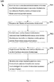
- Fig. 2 shows a flowchart 200 with method steps 201-205 of an exemplary embodiment of the method according to the invention.
- the device 1 can determine a first geometry information, in particular a measure of the size of the surface of the first package stream 12 (action 201). Subsequently, the packets pass to the second conveyor 20 (action 202).
- the device 1 can determine a second geometry information, in particular a measure of the size of the surface of the second package stream 22 (action 203).
- the first speed 13 of the first conveyor belt 10 and / or the second speed 23 of the second conveyor belt 20 can now be adjusted (action 205).
- a gap distribution between the packages 2 of the second package stream 22 can be adjusted in a targeted manner.
- the distance 24 between in each case two adjacent packages 2 of the second package stream 22 is, for example, preferably between 1.2 m and 5 m for the packages.
- Fig. 3 shows a flowchart 300 with method steps 301 - 305 of an exemplary second embodiment of the method according to the invention.
- the device 1 first determines first geometry information comprising a height profile of the first package flow 12 (action 301).
- v Q ⁇ V n / (B ⁇ H) is now determined by means of the height profile, in particular the width and height, that is, the cross-sectional area B ⁇ H of the package stream 12 and an assumption for the volume V n of a package piece 2 depending on the required throughput Q, the first speed 13 of the first conveyor belt 10 and / or the second speed 23 of the second conveyor belt 20 are set (action 302).
- the device 1 determines a second geometry information comprising a height profile of the second package stream 22 (action 204).
- height information of individual packages can also be determined by means of the height profile, so that in particular the assumption for V n can be verified.
- the first speed 13 of the first conveyor belt 10 can be adjusted again and / or the second speed 23 of the second conveyor belt 20 adjusted based on the first and the second geometry information (action 205).
Landscapes
- Engineering & Computer Science (AREA)
- Mechanical Engineering (AREA)
- General Engineering & Computer Science (AREA)
- Manufacturing & Machinery (AREA)
- Quality & Reliability (AREA)
- Physics & Mathematics (AREA)
- General Physics & Mathematics (AREA)
- Automation & Control Theory (AREA)
- Control Of Conveyors (AREA)
Applications Claiming Priority (1)
| Application Number | Priority Date | Filing Date | Title |
|---|---|---|---|
| DE102016111110.4A DE102016111110A1 (de) | 2016-06-17 | 2016-06-17 | Ansteuerung von Fördermitteln |
Publications (3)
| Publication Number | Publication Date |
|---|---|
| EP3293592A1 true EP3293592A1 (fr) | 2018-03-14 |
| EP3293592C0 EP3293592C0 (fr) | 2023-06-07 |
| EP3293592B1 EP3293592B1 (fr) | 2023-06-07 |
Family
ID=59034567
Family Applications (1)
| Application Number | Title | Priority Date | Filing Date |
|---|---|---|---|
| EP17175170.4A Active EP3293592B1 (fr) | 2016-06-17 | 2017-06-09 | Controle de convoyeurs |
Country Status (4)
| Country | Link |
|---|---|
| US (1) | US10647520B2 (fr) |
| EP (1) | EP3293592B1 (fr) |
| CN (1) | CN107521907B (fr) |
| DE (1) | DE102016111110A1 (fr) |
Families Citing this family (25)
| Publication number | Priority date | Publication date | Assignee | Title |
|---|---|---|---|---|
| US10315859B1 (en) * | 2017-03-20 | 2019-06-11 | Amazon Technologies, Inc. | Automatic singulation of items |
| DE102017106533B4 (de) * | 2017-03-27 | 2019-10-10 | Sick Ag | Vorrichtung und Verfahren zum Positionieren von Objekten |
| US11440744B2 (en) | 2018-07-30 | 2022-09-13 | Laitram, L.L.C. | Conveyor package-flow measuring system |
| CN112689603B (zh) | 2018-09-07 | 2022-10-04 | 派克赛泽有限责任公司 | 用于包装机的自适应加速控制 |
| US10781053B1 (en) | 2018-12-13 | 2020-09-22 | Amazon Technologies, Inc. | Control system for automated singulation system |
| US10961060B1 (en) * | 2018-12-13 | 2021-03-30 | Amazon Technologies, Inc. | Automated singulation system |
| US11724887B2 (en) * | 2019-01-03 | 2023-08-15 | Körber Supply Chain Llc | System and method for fix pitch parcel distribution |
| US10807808B1 (en) * | 2019-04-22 | 2020-10-20 | Amazon Technologies, Inc. | Systems and methods for automated item separation and presentation |
| US20220169450A1 (en) * | 2019-04-25 | 2022-06-02 | Siemens Logistics Llc | System and method for parcel accumulation and normalization |
| DE102019114469B4 (de) * | 2019-05-29 | 2025-10-16 | Deutsche Post Ag | Verfahren zur Überwachung und/oder Instandhaltung einer Förderanlage und Förderanlage |
| JP7388855B2 (ja) * | 2019-09-18 | 2023-11-29 | 東芝テック株式会社 | コンベア |
| US11537982B1 (en) | 2019-10-11 | 2022-12-27 | Amazon Technologies, Inc. | Inventory sorting and transport |
| US11407595B2 (en) * | 2019-12-10 | 2022-08-09 | Intelligrated Headquarters, Llc | Methods and apparatuses for performing article singulation |
| US11230435B1 (en) | 2019-12-12 | 2022-01-25 | Amazon Technologies, Inc. | Multi-asin consolidation and transportation system |
| US11420823B1 (en) | 2019-12-12 | 2022-08-23 | Amazon Technologies, Inc. | Consolidation and transportation of items |
| EP4110712A4 (fr) * | 2020-02-24 | 2024-03-20 | Material Handling Systems, Inc. | Système de gestion de flux de colis avec un transporteur de retenue |
| NL2025084B1 (en) | 2020-03-09 | 2021-10-19 | Rexnord Flattop Europe Bv | Flow control of product transport |
| EP3971116A1 (fr) * | 2020-09-17 | 2022-03-23 | Caljan A/S | Systèmes, dispositifs et procédés pour transporteurs extensibles |
| US11420828B1 (en) * | 2020-12-11 | 2022-08-23 | Amazon Technologies, Inc. | System and method for item singulation |
| CN115367407B (zh) * | 2021-05-19 | 2025-08-08 | 威海新北洋正棋机器人股份有限公司 | 物件处理设备和物件处理方法 |
| WO2022256887A1 (fr) * | 2021-06-07 | 2022-12-15 | MARTINS, Andrea Luciana | Procédé et dispositif pour l'empaquetage d'emballages cartonnés |
| CN115924492A (zh) * | 2021-08-16 | 2023-04-07 | 山东新北洋信息技术股份有限公司 | 包裹分离方法和设备 |
| JP2023045031A (ja) | 2021-09-21 | 2023-04-03 | 株式会社東芝 | 供給装置 |
| EP4159650B1 (fr) | 2021-09-29 | 2025-06-04 | Fameccanica.Data S.p.A. | Procédé permettant de modifier l'agencement spatial de produits |
| US12371265B2 (en) | 2021-10-12 | 2025-07-29 | Intelligrated Headquarters, Llc | Methods, apparatuses and computer program products for providing dynamic control in automated storage and retrieval systems |
Citations (7)
| Publication number | Priority date | Publication date | Assignee | Title |
|---|---|---|---|---|
| EP0174168A1 (fr) * | 1984-08-31 | 1986-03-12 | Rheon Automatic Machinery Co. Ltd. | Procédé de mesure continue d'un corps allongé transporté sur un convoyeur |
| EP0245806A2 (fr) * | 1986-05-13 | 1987-11-19 | Seitz Enzinger Noll Maschinenbau Aktiengesellschaft | Transporteur d'accumulation fonctionnant en tant qu'accumulateur pour un transporteur d'un dispositif de traitement de bouteilles ou récipients similaires |
| WO2000066280A2 (fr) * | 1999-04-30 | 2000-11-09 | Siemens Electrocom, L.P. | Systeme de separation d'elements |
| US20010035332A1 (en) * | 2000-05-11 | 2001-11-01 | Zeitler David W. | Conveyor induction system |
| EP3020660A1 (fr) * | 2014-11-12 | 2016-05-18 | Krones AG | Dispositif et procede de determination d'un degre d'occupation d'un dispositif de transport |
| WO2016082950A1 (fr) * | 2014-11-26 | 2016-06-02 | Siemens Aktiengesellschaft | Procédé pour réunir des produits à emballer et dispositif de transport de produits à emballer |
| WO2016108937A1 (fr) * | 2014-12-31 | 2016-07-07 | Fives Intralogistics Corp. | Système de gestion d'emballages de transporteur basé sur la vision |
Family Cites Families (7)
| Publication number | Priority date | Publication date | Assignee | Title |
|---|---|---|---|---|
| US6471044B1 (en) * | 1999-04-30 | 2002-10-29 | Siemens Electrocom, L.P. | Hold and release singulator |
| US6910569B2 (en) * | 2002-01-29 | 2005-06-28 | Siemens Technology-To-Business Center, Llc | Load singulation system and method |
| DK1556297T3 (da) * | 2002-10-29 | 2008-07-21 | Siemens Ag | Transportindretning med håndtering af fordelte genstande |
| CN101027236A (zh) * | 2004-06-21 | 2007-08-29 | 西门子共同研究公司 | 高速率节省空间的物品单一化装置 |
| CA2735512A1 (fr) * | 2010-04-01 | 2011-10-01 | Siemens Aktiengesellschaft | Procede et appareil pour la mesure d'un parametre pendant le transport d'objets vers un dispositif de traitement |
| CN103748024B (zh) * | 2011-06-07 | 2017-02-15 | 康尔富盛德国326有限公司 | 将存入自动化仓库的计件货物分离的装置 |
| US10061308B2 (en) * | 2016-09-16 | 2018-08-28 | Siemens Industry, Inc. | Parcel delayering systems and methods for automatic parcel processing based on accurate de-layering |
-
2016
- 2016-06-17 DE DE102016111110.4A patent/DE102016111110A1/de active Pending
-
2017
- 2017-06-09 EP EP17175170.4A patent/EP3293592B1/fr active Active
- 2017-06-14 US US15/622,784 patent/US10647520B2/en active Active
- 2017-06-19 CN CN201710463664.5A patent/CN107521907B/zh active Active
Patent Citations (7)
| Publication number | Priority date | Publication date | Assignee | Title |
|---|---|---|---|---|
| EP0174168A1 (fr) * | 1984-08-31 | 1986-03-12 | Rheon Automatic Machinery Co. Ltd. | Procédé de mesure continue d'un corps allongé transporté sur un convoyeur |
| EP0245806A2 (fr) * | 1986-05-13 | 1987-11-19 | Seitz Enzinger Noll Maschinenbau Aktiengesellschaft | Transporteur d'accumulation fonctionnant en tant qu'accumulateur pour un transporteur d'un dispositif de traitement de bouteilles ou récipients similaires |
| WO2000066280A2 (fr) * | 1999-04-30 | 2000-11-09 | Siemens Electrocom, L.P. | Systeme de separation d'elements |
| US20010035332A1 (en) * | 2000-05-11 | 2001-11-01 | Zeitler David W. | Conveyor induction system |
| EP3020660A1 (fr) * | 2014-11-12 | 2016-05-18 | Krones AG | Dispositif et procede de determination d'un degre d'occupation d'un dispositif de transport |
| WO2016082950A1 (fr) * | 2014-11-26 | 2016-06-02 | Siemens Aktiengesellschaft | Procédé pour réunir des produits à emballer et dispositif de transport de produits à emballer |
| WO2016108937A1 (fr) * | 2014-12-31 | 2016-07-07 | Fives Intralogistics Corp. | Système de gestion d'emballages de transporteur basé sur la vision |
Non-Patent Citations (1)
| Title |
|---|
| HASSAN K. KHALIL: "Nonlinear Systems", VERLAG PRENTICE-HALL |
Also Published As
| Publication number | Publication date |
|---|---|
| EP3293592C0 (fr) | 2023-06-07 |
| US20170362036A1 (en) | 2017-12-21 |
| US10647520B2 (en) | 2020-05-12 |
| DE102016111110A1 (de) | 2017-12-21 |
| DE102016111110A9 (de) | 2018-03-08 |
| CN107521907A (zh) | 2017-12-29 |
| CN107521907B (zh) | 2021-02-23 |
| EP3293592B1 (fr) | 2023-06-07 |
Similar Documents
| Publication | Publication Date | Title |
|---|---|---|
| EP3293592B1 (fr) | Controle de convoyeurs | |
| DE102015117241B4 (de) | Ansteuerung einer Förderanlage | |
| EP3038818A1 (fr) | Procédé et dispositif de production d'un matériau de départ pour pneus de véhicules | |
| EP2375380A1 (fr) | Procédé et dispositif de mesure d'un paramètre lors du transport d'objets vers un dispositif de traitement | |
| EP2181311B1 (fr) | Procédé et dispositif de pesée dynamique de contrôle | |
| EP4034482B1 (fr) | Procédé de configuration par ordinateur d'une application d'entraînement régulée d'un système logistique | |
| EP3395728A1 (fr) | Réglage de l'écart entre des marchandises au détail à acheminer | |
| DE102011116535A1 (de) | Verfahren und Vorrichtung zum Ausrichten eines nicht-kreisrunden oder mehreckigen Gegenstands | |
| EP4150317B1 (fr) | Procédé de détermination de la répartition granulométrique de parties d'un matériau en vrac introduit sur une bande transporteuse | |
| DE102014102203A1 (de) | Verfahren zum Transportieren von Kunststoffvorformlingen, Vorrichtung zum Transportieren von Kunststoffvorformlingen und Schaltungsanordnung für eine derartige Vorrichtung | |
| DE102005063193A1 (de) | Vorrichtung und Verfahren zum Gruppieren von Stückgut | |
| EP3964460A1 (fr) | Dispositif et procédé d'alignement de produits en vrac | |
| CH719300A1 (de) | Verfahren und Vorrichtung zum phasengenauen Übergeben von Stückgut. | |
| EP2818254B1 (fr) | Dispositif de séparation d'objets | |
| EP2181312B1 (fr) | Procédé et dispositif de pesée dynamique de contrôle | |
| EP4149688A1 (fr) | Procédé de contrôle des poussières dans des concasseurs équipés de dispositifs de pulvérisation | |
| EP4302159B1 (fr) | Procédé mis en uvre par ordinateur, dispositif de traitement des données et système informatique permettant de commander un dispositif de régulation d'un système de transport | |
| EP2777902B1 (fr) | Procédé d'usinage d'arêtes de pièces en forme de plaques | |
| EP3572161B1 (fr) | Procédé et dispositif de fabrication d'un produit de matériau en bande laminé flexible | |
| AT523805B1 (de) | Verfahren zur Verschleißerkennung bei Brechern in Leerfahrt | |
| DE112019007901B4 (de) | Informationsverarbeitungsvorrichtung, steuerverfahren, steuerprogramm und informationsbereitstellungssystem | |
| DE202017004165U1 (de) | Vorrichtung zum Wiegen eines Produkts in einer Fertigungslinie | |
| WO2021226646A1 (fr) | Procédé de détermination, par parts, du volume d'un matériau en vrac amené sur une bande transporteuse | |
| EP4553591A1 (fr) | Système de transport pour transporter une marchandise, procédé de réglage de zones d'un système de transport, programme informatique et dispositif de traitement de données | |
| DE202025104284U1 (de) | Vorrichtung zum Wiegen von geförderten Produkten im Rückwärtsbetrieb |
Legal Events
| Date | Code | Title | Description |
|---|---|---|---|
| PUAI | Public reference made under article 153(3) epc to a published international application that has entered the european phase |
Free format text: ORIGINAL CODE: 0009012 |
|
| STAA | Information on the status of an ep patent application or granted ep patent |
Free format text: STATUS: THE APPLICATION HAS BEEN PUBLISHED |
|
| AK | Designated contracting states |
Kind code of ref document: A1 Designated state(s): AL AT BE BG CH CY CZ DE DK EE ES FI FR GB GR HR HU IE IS IT LI LT LU LV MC MK MT NL NO PL PT RO RS SE SI SK SM TR |
|
| AX | Request for extension of the european patent |
Extension state: BA ME |
|
| STAA | Information on the status of an ep patent application or granted ep patent |
Free format text: STATUS: REQUEST FOR EXAMINATION WAS MADE |
|
| 17P | Request for examination filed |
Effective date: 20180905 |
|
| RBV | Designated contracting states (corrected) |
Designated state(s): AL AT BE BG CH CY CZ DE DK EE ES FI FR GB GR HR HU IE IS IT LI LT LU LV MC MK MT NL NO PL PT RO RS SE SI SK SM TR |
|
| STAA | Information on the status of an ep patent application or granted ep patent |
Free format text: STATUS: EXAMINATION IS IN PROGRESS |
|
| 17Q | First examination report despatched |
Effective date: 20201110 |
|
| GRAP | Despatch of communication of intention to grant a patent |
Free format text: ORIGINAL CODE: EPIDOSNIGR1 |
|
| STAA | Information on the status of an ep patent application or granted ep patent |
Free format text: STATUS: GRANT OF PATENT IS INTENDED |
|
| INTG | Intention to grant announced |
Effective date: 20221209 |
|
| GRAS | Grant fee paid |
Free format text: ORIGINAL CODE: EPIDOSNIGR3 |
|
| GRAA | (expected) grant |
Free format text: ORIGINAL CODE: 0009210 |
|
| STAA | Information on the status of an ep patent application or granted ep patent |
Free format text: STATUS: THE PATENT HAS BEEN GRANTED |
|
| AK | Designated contracting states |
Kind code of ref document: B1 Designated state(s): AL AT BE BG CH CY CZ DE DK EE ES FI FR GB GR HR HU IE IS IT LI LT LU LV MC MK MT NL NO PL PT RO RS SE SI SK SM TR |
|
| REG | Reference to a national code |
Ref country code: GB Ref legal event code: FG4D Free format text: NOT ENGLISH |
|
| REG | Reference to a national code |
Ref country code: CH Ref legal event code: EP Ref country code: AT Ref legal event code: REF Ref document number: 1576956 Country of ref document: AT Kind code of ref document: T Effective date: 20230615 |
|
| REG | Reference to a national code |
Ref country code: DE Ref legal event code: R096 Ref document number: 502017014793 Country of ref document: DE |
|
| U01 | Request for unitary effect filed |
Effective date: 20230705 |
|
| U07 | Unitary effect registered |
Designated state(s): AT BE BG DE DK EE FI FR IT LT LU LV MT NL PT SE SI Effective date: 20230714 |
|
| U20 | Renewal fee for the european patent with unitary effect paid |
Year of fee payment: 7 Effective date: 20230713 |
|
| REG | Reference to a national code |
Ref country code: LT Ref legal event code: MG9D |
|
| PG25 | Lapsed in a contracting state [announced via postgrant information from national office to epo] |
Ref country code: NO Free format text: LAPSE BECAUSE OF FAILURE TO SUBMIT A TRANSLATION OF THE DESCRIPTION OR TO PAY THE FEE WITHIN THE PRESCRIBED TIME-LIMIT Effective date: 20230907 Ref country code: ES Free format text: LAPSE BECAUSE OF FAILURE TO SUBMIT A TRANSLATION OF THE DESCRIPTION OR TO PAY THE FEE WITHIN THE PRESCRIBED TIME-LIMIT Effective date: 20230607 |
|
| PG25 | Lapsed in a contracting state [announced via postgrant information from national office to epo] |
Ref country code: RS Free format text: LAPSE BECAUSE OF FAILURE TO SUBMIT A TRANSLATION OF THE DESCRIPTION OR TO PAY THE FEE WITHIN THE PRESCRIBED TIME-LIMIT Effective date: 20230607 Ref country code: HR Free format text: LAPSE BECAUSE OF FAILURE TO SUBMIT A TRANSLATION OF THE DESCRIPTION OR TO PAY THE FEE WITHIN THE PRESCRIBED TIME-LIMIT Effective date: 20230607 Ref country code: GR Free format text: LAPSE BECAUSE OF FAILURE TO SUBMIT A TRANSLATION OF THE DESCRIPTION OR TO PAY THE FEE WITHIN THE PRESCRIBED TIME-LIMIT Effective date: 20230908 |
|
| PG25 | Lapsed in a contracting state [announced via postgrant information from national office to epo] |
Ref country code: SK Free format text: LAPSE BECAUSE OF FAILURE TO SUBMIT A TRANSLATION OF THE DESCRIPTION OR TO PAY THE FEE WITHIN THE PRESCRIBED TIME-LIMIT Effective date: 20230607 |
|
| PG25 | Lapsed in a contracting state [announced via postgrant information from national office to epo] |
Ref country code: IS Free format text: LAPSE BECAUSE OF FAILURE TO SUBMIT A TRANSLATION OF THE DESCRIPTION OR TO PAY THE FEE WITHIN THE PRESCRIBED TIME-LIMIT Effective date: 20231007 |
|
| PG25 | Lapsed in a contracting state [announced via postgrant information from national office to epo] |
Ref country code: SM Free format text: LAPSE BECAUSE OF FAILURE TO SUBMIT A TRANSLATION OF THE DESCRIPTION OR TO PAY THE FEE WITHIN THE PRESCRIBED TIME-LIMIT Effective date: 20230607 Ref country code: SK Free format text: LAPSE BECAUSE OF FAILURE TO SUBMIT A TRANSLATION OF THE DESCRIPTION OR TO PAY THE FEE WITHIN THE PRESCRIBED TIME-LIMIT Effective date: 20230607 Ref country code: RO Free format text: LAPSE BECAUSE OF FAILURE TO SUBMIT A TRANSLATION OF THE DESCRIPTION OR TO PAY THE FEE WITHIN THE PRESCRIBED TIME-LIMIT Effective date: 20230607 Ref country code: IS Free format text: LAPSE BECAUSE OF FAILURE TO SUBMIT A TRANSLATION OF THE DESCRIPTION OR TO PAY THE FEE WITHIN THE PRESCRIBED TIME-LIMIT Effective date: 20231007 Ref country code: CZ Free format text: LAPSE BECAUSE OF FAILURE TO SUBMIT A TRANSLATION OF THE DESCRIPTION OR TO PAY THE FEE WITHIN THE PRESCRIBED TIME-LIMIT Effective date: 20230607 |
|
| REG | Reference to a national code |
Ref country code: CH Ref legal event code: PL |
|
| PG25 | Lapsed in a contracting state [announced via postgrant information from national office to epo] |
Ref country code: PL Free format text: LAPSE BECAUSE OF FAILURE TO SUBMIT A TRANSLATION OF THE DESCRIPTION OR TO PAY THE FEE WITHIN THE PRESCRIBED TIME-LIMIT Effective date: 20230607 |
|
| REG | Reference to a national code |
Ref country code: DE Ref legal event code: R097 Ref document number: 502017014793 Country of ref document: DE |
|
| PG25 | Lapsed in a contracting state [announced via postgrant information from national office to epo] |
Ref country code: MC Free format text: LAPSE BECAUSE OF FAILURE TO SUBMIT A TRANSLATION OF THE DESCRIPTION OR TO PAY THE FEE WITHIN THE PRESCRIBED TIME-LIMIT Effective date: 20230607 |
|
| REG | Reference to a national code |
Ref country code: IE Ref legal event code: MM4A |
|
| PG25 | Lapsed in a contracting state [announced via postgrant information from national office to epo] |
Ref country code: MC Free format text: LAPSE BECAUSE OF FAILURE TO SUBMIT A TRANSLATION OF THE DESCRIPTION OR TO PAY THE FEE WITHIN THE PRESCRIBED TIME-LIMIT Effective date: 20230607 |
|
| PLBE | No opposition filed within time limit |
Free format text: ORIGINAL CODE: 0009261 |
|
| STAA | Information on the status of an ep patent application or granted ep patent |
Free format text: STATUS: NO OPPOSITION FILED WITHIN TIME LIMIT |
|
| PG25 | Lapsed in a contracting state [announced via postgrant information from national office to epo] |
Ref country code: IE Free format text: LAPSE BECAUSE OF NON-PAYMENT OF DUE FEES Effective date: 20230609 |
|
| PG25 | Lapsed in a contracting state [announced via postgrant information from national office to epo] |
Ref country code: IE Free format text: LAPSE BECAUSE OF NON-PAYMENT OF DUE FEES Effective date: 20230609 Ref country code: CH Free format text: LAPSE BECAUSE OF NON-PAYMENT OF DUE FEES Effective date: 20230630 |
|
| 26N | No opposition filed |
Effective date: 20240308 |
|
| U20 | Renewal fee for the european patent with unitary effect paid |
Year of fee payment: 8 Effective date: 20240620 |
|
| PGFP | Annual fee paid to national office [announced via postgrant information from national office to epo] |
Ref country code: GB Payment date: 20250624 Year of fee payment: 9 |
|
| PG25 | Lapsed in a contracting state [announced via postgrant information from national office to epo] |
Ref country code: CY Free format text: LAPSE BECAUSE OF FAILURE TO SUBMIT A TRANSLATION OF THE DESCRIPTION OR TO PAY THE FEE WITHIN THE PRESCRIBED TIME-LIMIT; INVALID AB INITIO Effective date: 20170609 |
|
| U20 | Renewal fee for the european patent with unitary effect paid |
Year of fee payment: 9 Effective date: 20250624 |
|
| PG25 | Lapsed in a contracting state [announced via postgrant information from national office to epo] |
Ref country code: HU Free format text: LAPSE BECAUSE OF FAILURE TO SUBMIT A TRANSLATION OF THE DESCRIPTION OR TO PAY THE FEE WITHIN THE PRESCRIBED TIME-LIMIT; INVALID AB INITIO Effective date: 20170609 |
|
| PG25 | Lapsed in a contracting state [announced via postgrant information from national office to epo] |
Ref country code: TR Free format text: LAPSE BECAUSE OF FAILURE TO SUBMIT A TRANSLATION OF THE DESCRIPTION OR TO PAY THE FEE WITHIN THE PRESCRIBED TIME-LIMIT Effective date: 20230607 |