EP3020903A1 - Support de capot - Google Patents
Support de capot Download PDFInfo
- Publication number
- EP3020903A1 EP3020903A1 EP14193365.5A EP14193365A EP3020903A1 EP 3020903 A1 EP3020903 A1 EP 3020903A1 EP 14193365 A EP14193365 A EP 14193365A EP 3020903 A1 EP3020903 A1 EP 3020903A1
- Authority
- EP
- European Patent Office
- Prior art keywords
- attachment
- fastening
- mounting
- range
- section
- Prior art date
- Legal status (The legal status is an assumption and is not a legal conclusion. Google has not performed a legal analysis and makes no representation as to the accuracy of the status listed.)
- Granted
Links
Images


Classifications
-
- E—FIXED CONSTRUCTIONS
- E05—LOCKS; KEYS; WINDOW OR DOOR FITTINGS; SAFES
- E05D—HINGES OR SUSPENSION DEVICES FOR DOORS, WINDOWS OR WINGS
- E05D15/00—Suspension arrangements for wings
- E05D15/06—Suspension arrangements for wings for wings sliding horizontally more or less in their own plane
- E05D15/0621—Details, e.g. suspension or supporting guides
- E05D15/0626—Details, e.g. suspension or supporting guides for wings suspended at the top
- E05D15/0652—Tracks
-
- F—MECHANICAL ENGINEERING; LIGHTING; HEATING; WEAPONS; BLASTING
- F16—ENGINEERING ELEMENTS AND UNITS; GENERAL MEASURES FOR PRODUCING AND MAINTAINING EFFECTIVE FUNCTIONING OF MACHINES OR INSTALLATIONS; THERMAL INSULATION IN GENERAL
- F16M—FRAMES, CASINGS OR BEDS OF ENGINES, MACHINES OR APPARATUS, NOT SPECIFIC TO ENGINES, MACHINES OR APPARATUS PROVIDED FOR ELSEWHERE; STANDS; SUPPORTS
- F16M13/00—Other supports for positioning apparatus or articles; Means for steadying hand-held apparatus or articles
- F16M13/02—Other supports for positioning apparatus or articles; Means for steadying hand-held apparatus or articles for supporting on, or attaching to, an object, e.g. tree, gate, window-frame, cycle
-
- E—FIXED CONSTRUCTIONS
- E05—LOCKS; KEYS; WINDOW OR DOOR FITTINGS; SAFES
- E05Y—INDEXING SCHEME ASSOCIATED WITH SUBCLASSES E05D AND E05F, RELATING TO CONSTRUCTION ELEMENTS, ELECTRIC CONTROL, POWER SUPPLY, POWER SIGNAL OR TRANSMISSION, USER INTERFACES, MOUNTING OR COUPLING, DETAILS, ACCESSORIES, AUXILIARY OPERATIONS NOT OTHERWISE PROVIDED FOR, APPLICATION THEREOF
- E05Y2201/00—Constructional elements; Accessories therefor
- E05Y2201/10—Covers; Housings
- E05Y2201/11—Covers
-
- E—FIXED CONSTRUCTIONS
- E05—LOCKS; KEYS; WINDOW OR DOOR FITTINGS; SAFES
- E05Y—INDEXING SCHEME ASSOCIATED WITH SUBCLASSES E05D AND E05F, RELATING TO CONSTRUCTION ELEMENTS, ELECTRIC CONTROL, POWER SUPPLY, POWER SIGNAL OR TRANSMISSION, USER INTERFACES, MOUNTING OR COUPLING, DETAILS, ACCESSORIES, AUXILIARY OPERATIONS NOT OTHERWISE PROVIDED FOR, APPLICATION THEREOF
- E05Y2600/00—Mounting or coupling arrangements for elements provided for in this subclass
- E05Y2600/50—Mounting methods; Positioning
- E05Y2600/52—Toolless
- E05Y2600/528—Hooking, e.g. using bayonets; Locking
-
- E—FIXED CONSTRUCTIONS
- E05—LOCKS; KEYS; WINDOW OR DOOR FITTINGS; SAFES
- E05Y—INDEXING SCHEME ASSOCIATED WITH SUBCLASSES E05D AND E05F, RELATING TO CONSTRUCTION ELEMENTS, ELECTRIC CONTROL, POWER SUPPLY, POWER SIGNAL OR TRANSMISSION, USER INTERFACES, MOUNTING OR COUPLING, DETAILS, ACCESSORIES, AUXILIARY OPERATIONS NOT OTHERWISE PROVIDED FOR, APPLICATION THEREOF
- E05Y2800/00—Details, accessories and auxiliary operations not otherwise provided for
- E05Y2800/26—Form or shape
- E05Y2800/27—Profiles; Strips
Definitions
- the present invention relates to a trim bracket for releasable attachment, in particular to a roller track of a sliding door system, a corresponding panel, a sliding door system and a method for mounting a panel on a roller track.
- a disadvantage of the known panels is that the implementation of the installation is relatively time consuming. So it is necessary to attach at least two, but often significantly more screws and screw into corresponding threaded holes. For this purpose, an assembly tool in the form of a screwdriver or a cordless screwdriver is also necessary. Not least, the complexity is increased by the necessary number of individual, small-part screws during assembly. All this leads to a higher expenditure of time and to a higher complexity and accordingly to a higher susceptibility to error in the attachment of such panels.
- a trim bracket according to the invention is used for releasable attachment, in particular on a roller track of a sliding door system.
- a fairing holder on a base, wherein on the base body, a holding portion for holding the roller track is formed.
- a first fastening section is provided or formed on the base body for attachment to a first counter-fastening section of the cladding in a first fastening direction.
- a second attachment portion spaced from the first attachment portion for attachment to a second counter-attachment portion of the fairing formed in a second attachment direction.
- the first attachment direction and the second attachment direction have a correlation angle in the range between 70 ° and 110 ° with each other.
- a fairing bracket according to the invention thus serves to replace the previously used in use known fasteners in the form of screws.
- the fairing holder has two basic functions. On the one hand, this is the holding function on the roller track of a sliding door system. On the other hand, this involves the attachment function of the panel itself. This now leads to the possibility of integrating these two functions separately from the roller track and separately from the panel in the panel bracket according to the invention. Any complexity is accordingly focused on the fairing mount and can be provided there by the geometric configurations. In particular, this leads to the fact that the components of the roller raceway and the lining can be designed inexpensively and simply, for example in the form of an extruded profile.
- the two functions can be distinguished more precisely from one another.
- Both functions ie the holding function and the fastening function, are preferably reversible.
- This can, for example, bring benefits if necessary access to the internal technical components, in the form of maintenance or in the repair of a defect.
- each of the two attachment portions has a defined attachment direction.
- This defined fastening direction is a directional vector which is aligned along a fastening movement, that is to say, for example, in the formation of a snap-locking functionality for the respective fastening section, the direction which provides this snap-lock function.
- the fastening directions can also be formed within a mounting direction range in the form of an open angle section with correspondingly large opening angles.
- a mounting movement which includes these two fastening movements.
- the total movement which consists of a variety of Individual movements fasten the cladding to the roller track using the cladding bracket.
- a fastening movement are specific individual movements of the assembly movement to understand, which each lead to the formation of the attachment function of the respective attachment portion.
- a division into the at least two fastening movements is now carried out within the assembly movement, which have different directions of movement due to their geometric configuration of the different attachment directions.
- a correspondingly high level of security against undesired removal is brought about by the in particular substantially vertical orientation of the two fastening directions relative to one another.
- a mutual stabilization will be present so that a loosening of a fastening section by the other fastening section is avoided due to its correspondingly correlating other fastening direction.
- a defined procedure is necessary, which explicitly performs the reverse order of the mounting movement.
- an assembly movement is in particular constructed such that the two attachment movements take place separately from each other in time.
- first a first fastening movement for the first attachment portion and only after the completion of a second attachment movement for the second attachment portion is performed.
- a fastening section is to be understood in particular as a snap-lock functionality. This can be made available by virtue of the fact that one or more fastening legs each form a fastening section. In this case, such a snap-locking function can be provided in particular by correspondingly elastic formation of individual material sections or fastening legs of the respective fastening section.
- a snap-locking function can be provided in particular by correspondingly elastic formation of individual material sections or fastening legs of the respective fastening section.
- the holding function is ensured by the holding section and can also be configured in snap-lock functionality.
- other technical solutions such as a frictional connection, a frictional connection and / or a positive connection within the meaning of the present invention for the holding function can be used.
- different functionalities for the holding section can be combined.
- the correlation angle in the sense of the present invention is the angle between the two attachment directions.
- the respective fastening movement is configured in particular perpendicularly or substantially perpendicular to the correlating fastening movement of the other fastening section.
- this correlation angle is spanned in a plane which is spanned by the two vectors of the attachment directions. On a roller track, this plane is perpendicular to the correspondingly formed direction of movement of a roller carriage on this roller track.
- this plane is perpendicular to the correspondingly formed direction of movement of a roller carriage on this roller track.
- the correlation angle is in the range between 85 ° and 95 °, in particular at 90 ° in a fairing bracket according to the invention.
- An exactly vertical design means that the later reversible feasible disassembly is set to an explicit reverse order of the individual movements for the individual mounting movements of the assembly movement. During assembly, this leads to a relief, since also in a defined and in particular preferably guided way an attachment and a juxtaposition of the individual fastening movements can take place.
- the base body has a contact surface for abutment with a counter surface of the lining.
- the contact surface is arranged in particular between the two attachment sections.
- Such a contact surface correlates with respect to their geometric extent with the counter-contact surface.
- these two surfaces are complementary or at least partially complementary.
- these are flat surfaces.
- such a correlation between contact surface and counter-contact surface can in particular provide a mechanical stabilization in the mounted state.
- sections, in particular edges of the trim bracket slide on the counter-contact surface, so that in this way a Guiding functionality for carrying out the assembly movement or parts of the assembly movement is ensured.
- the counter-bearing surface acts in such a case as a guide means for mounting or fixing the fairing bracket to the panel.
- the preceding list is a non-exhaustive list.
- a range between 0.75 and 1.25 is provided for the correlations between the contact surface and the respective fastening legs.
- a ratio between 0.9 and 1.1 is preferred for this ratio.
- a range between 1 and 2.5, particularly preferably a range between 1 and 2 can be provided for the ratio between contact surface and holding section.
- much of the present training is the Basic body formed with identical or substantially identical wall thickness. If different wall thicknesses are provided, these are formed in the above limits only by small wall thickness jumps, so that facilitated manufacturability of the trim bracket becomes possible.
- an injection molding process and thus a fairing holder made of plastic, in particular of thermoplastic material are used.
- the first fastening section and / or the second fastening section each have a first fastening leg and a second fastening leg.
- the two attachment legs with each other in particular include a mounting angle in the range between 75 ° and 290 °. The larger this mounting angle is formed, the freer the orientation in the attachment. The larger this mounting angle, the wider a corresponding vector region is formed in which the fastening direction according to the invention is formed. If such a design is provided, bringing a particularly wide mounting bracket easier assembly with it.
- a correspondingly smaller selection of possible attachment directions is defined for a reduction of a corresponding angular range for the attachment vector. This ensures increased security of the fairing bracket in the attached state.
- a pivoting movement is possible by carrying out the subsequent and final fastening movement by means of a corresponding fastening angle.
- a further advantage may be when, in a trim bracket according to the invention, the first fastening portion and / or the second fastening portion are formed for a positive and / or non-positive attachment to the respective counter-fastening portion, in particular in the form of a snap-lock connection.
- fastening legs of the fastening sections are provided for such a snap-locking connection.
- Form-fitting and / or non-positive attachments are available, for example, by the respective attachment portion, in particular in a part or in a mounting leg, is formed in an elastic manner. This leads to an elastic deformation, wherein the engagement in the form of a latching movement is provided by the elastic restoring forces in the respective material.
- the provision of a snap-lock connection for one or both mounting portions also leads to a higher security during assembly, since both a haptic, as well as an acoustic feedback by the snapping indicates the termination of the respective fastening movement.
- the holding portion for a pivoting and / or rotating attachment to a roller track has a plate-shaped extension with a width which is smaller than the length of this plate-shaped extension.
- the holding section thus serves to fulfill the corresponding holding function in a rotational movement or in a pivoting movement.
- an associated groove may be formed on the roller track.
- This groove is thus preferably formed at least on one or preferably on both sides with an undercut, behind which the corresponding end faces of such a plate-shaped holding portion can engage.
- This may be a positive connection, which is associated with a frictional connection, in particular precisely fitting.
- the holding section it is also possible in principle for the holding section to have a movement clearance within such a groove, so that this holding section is displaceably mounted in the groove. This makes it easier after adjusting the holding function, so after inserting the holding section in the groove, then to ensure a lateral displacement. The flexibility during assembly is increased in this way.
- the base body is monolithic and forms the holding section, the first fastening section and / or the second fastening section in an integral manner.
- a monolithic or integral formation is to be understood as an integral formation. This relates in particular to a single material for all these component sections.
- a multi-component injection molding process for example as a production mold, a multi-material formation for such a monolithic form of the basic body is produced.
- the base body in particular in the region of Holding portion, at least two reinforcing ribs for mechanical reinforcement, which are preferably parallel to each other.
- a holding section for example, provided with a contact surface, which points in the direction of the bottom of a corresponding groove of the roller track, this may be referred to as the front.
- the corresponding rear side is preferably reinforced by this embodiment with the at least two reinforcing ribs.
- the mechanical reinforcement serves to save material in a rib-shaped manner and, in particular, to ensure a wall thickness correlation with regard to the transitions which is advantageous for an injection molding process.
- the parallel design also leads to provide a simplified shaping in injection molding.
- the two fastening portions are formed for two at least partially different fastening movements.
- the type of fastening movement is to be aimed in particular so that on the one hand the first fastening movement preferably takes place in a purely translatory manner or at least in its end in a translatory manner.
- the second fastening movement with respect to the second fastening portion is preferably provided at least partially pivoting or rotationally available. In this way, the two separate types of movement of the two movement sections can be distinguished more precisely from each other, whereby in particular the disassembly is provided in a defined manner and above all in a secure manner.
- a cover for covering a roller track of a sliding door system.
- a panel has a first counter-fastening section to Attaching a first mounting portion of a trim bracket according to the present invention along a first fastening direction.
- a second counter fastening section is provided for fastening a second fastening section of this trim bracket along a second fastening direction.
- the two attachment directions have a correlation angle in the range between 70 ° and 110 ° with each other.
- Another object of the present invention is a sliding door system, comprising a roller track and at least one slidably mounted in the roller track roller carriage.
- a sliding door system according to the invention is characterized in that the roller track is covered by a cladding according to the present invention, which is fastened with at least one cladding bracket according to the present invention. Even so brings a sliding door system according to the invention with the same advantages, as they have been explained in detail with respect to a trim bracket according to the invention.
- a method according to the invention brings about the same advantages as have been explained in detail with reference to a trim support according to the invention.
- a rotational fastening movement in the range between 15 ° and 135 °.
- This rotational movement makes it possible to provide an explicit distinction to a shifting and / or translational fastening movement of the fastening sections, as will be explained below.
- a rotational movement takes place about an axis which is provided substantially along the direction of gravity in the mounted position of the roller track.
- a rotation in the range of about 90 ° ⁇ 10 ° takes place here to a clear distinction between tween the different positions and at the same time to provide a reduced extent of the necessary fastening movement.
- the two preceding attachment steps can be performed both in combination and each individually.
- the dismantling takes place in accordance with the invention in reverse order.
- the subject of the present invention is accordingly a corresponding method for disassembling the cladding, the above description, in particular relating to claims 13 to 15, correspondingly being carried out in the individual movement in the reverse order for such a disassembly method.
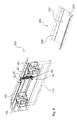
- a first trim bracket 10 is shown. This is equipped with a base body 20, which is provided here by injection molding as a plastic component available. At the top and at the bottom of a respective attachment portion 40 and 50 is provided, wherein at the upper end to the left in addition, the holding portion 30 can be seen.
- the mechanical stabilization holding portion 30 is provided with a plurality of Reinforcing ribs 32 provided which provide a corresponding mechanical stabilization.
- the two mounting portions 40 and 50 are here equipped with a snap-lock functionality.
- the second attachment portion 50 is equipped with a first attachment leg 52 or two such second attachment leg 52 and a second attachment leg 54.
- the base body 20 has a substantially flat longitudinal extent, which is provided on the rear side with a contact surface 22.
- the direction of gravity SKR is based on the corresponding mounting situation in the installation of such a fairing holder 10th
- Fig. 2 shows now the correlation of the self-adjusting angle in such a fairing bracket 10.
- the first mounting portion 40 is here provided with two mounting legs 44 and 42, which together include a corresponding mounting bracket ⁇ .
- Such an attachment angle ⁇ is also defined by the two attachment legs 52 and 54 of the second attachment portion 50.
- These two attachment angles ⁇ can be designed differently and are preferably each available in the range between 75 ° and 290 °.
- Fig. 2 shown are the two mounting directions B1 and B2 of the two fastening portions 40 and 50, which here perpendicular to each other, so that the correlation angle ⁇ between the two mounting directions B1 and B2 is 90 ° here. This leads to the later explained possibility of the entire assembly movement.
- Fig. 4 also shows the fulfillment of the holding function, in which the holding portion 30 is arranged in an associated retaining groove 130 of the roller race 120.
Landscapes
- Engineering & Computer Science (AREA)
- Mechanical Engineering (AREA)
- General Engineering & Computer Science (AREA)
- Injection Moulding Of Plastics Or The Like (AREA)
- Support Devices For Sliding Doors (AREA)
- Spray Control Apparatus (AREA)
- Coating Apparatus (AREA)
- Clamps And Clips (AREA)
- Vehicle Interior And Exterior Ornaments, Soundproofing, And Insulation (AREA)
Priority Applications (4)
| Application Number | Priority Date | Filing Date | Title |
|---|---|---|---|
| EP14193365.5A EP3020903B1 (fr) | 2014-11-14 | 2014-11-14 | Support de capot |
| ES14193365T ES2904831T3 (es) | 2014-11-14 | 2014-11-14 | Soporte de revestimiento |
| US14/939,045 US20160138316A1 (en) | 2014-11-14 | 2015-11-12 | Cover holder |
| CN201510779359.8A CN105604429B (zh) | 2014-11-14 | 2015-11-13 | 包覆件保持装置 |
Applications Claiming Priority (1)
| Application Number | Priority Date | Filing Date | Title |
|---|---|---|---|
| EP14193365.5A EP3020903B1 (fr) | 2014-11-14 | 2014-11-14 | Support de capot |
Publications (2)
| Publication Number | Publication Date |
|---|---|
| EP3020903A1 true EP3020903A1 (fr) | 2016-05-18 |
| EP3020903B1 EP3020903B1 (fr) | 2021-11-10 |
Family
ID=51900781
Family Applications (1)
| Application Number | Title | Priority Date | Filing Date |
|---|---|---|---|
| EP14193365.5A Revoked EP3020903B1 (fr) | 2014-11-14 | 2014-11-14 | Support de capot |
Country Status (4)
| Country | Link |
|---|---|
| US (1) | US20160138316A1 (fr) |
| EP (1) | EP3020903B1 (fr) |
| CN (1) | CN105604429B (fr) |
| ES (1) | ES2904831T3 (fr) |
Families Citing this family (4)
| Publication number | Priority date | Publication date | Assignee | Title |
|---|---|---|---|---|
| ES2886502T3 (es) * | 2018-05-17 | 2021-12-20 | Kesseboehmer Holding Kg | Herraje de tapa para la fijación pivotante de una tapa de mueble a una carcasa de mueble |
| SE544135C2 (en) * | 2020-05-04 | 2022-01-11 | Ikea Supply Ag | Sliding closet door assembly, bypass door assembly, and method for connecting a sliding door |
| GB2600162B (en) * | 2020-10-26 | 2023-04-26 | Blindspace Ab | A cover arrangement |
| US20260075726A1 (en) * | 2024-09-11 | 2026-03-12 | Xue-feng Chen | Router power supply support rack |
Citations (3)
| Publication number | Priority date | Publication date | Assignee | Title |
|---|---|---|---|---|
| EP2453087A1 (fr) * | 2010-11-16 | 2012-05-16 | Eledyna Technology Corp. | Structure de châssis dotée d'un mécanisme de rétention de couvercle |
| DE102012203726B3 (de) * | 2012-03-09 | 2013-06-06 | Geze Gmbh | Schiebetüranordnung |
| FR2997992A1 (fr) * | 2012-11-12 | 2014-05-16 | Financ Tirard Sas | Installation de fermeture a panneaux coulissants |
Family Cites Families (19)
| Publication number | Priority date | Publication date | Assignee | Title |
|---|---|---|---|---|
| US3473266A (en) * | 1967-12-15 | 1969-10-21 | Stanley Works | Integrated header |
| US3983600A (en) * | 1976-02-20 | 1976-10-05 | Arthur Cox & Sons Inc. | By-passing door fascia assembly |
| DE4015870C2 (de) * | 1990-05-17 | 1994-02-17 | Hespe & Woelm Gmbh & Co Kg | Schiebetür |
| US5274499A (en) * | 1992-09-04 | 1993-12-28 | Draper Shade & Screen Co., Inc. | Battery operated projection screen with spring assisted roller and replaceable fascia |
| US6111694A (en) * | 1997-05-23 | 2000-08-29 | Draper, Inc. | Casing for projection screen system |
| DE19804860C1 (de) * | 1998-02-09 | 1999-08-26 | Dorma Gmbh & Co Kg | Gehäuse, insbesondere für automatische Türantriebe |
| DE29807556U1 (de) * | 1998-04-30 | 1999-06-02 | Automatik-Tür-Systeme GmbH, 33378 Rheda-Wiedenbrück | Schiebetüranlage |
| US6983512B2 (en) * | 2002-07-23 | 2006-01-10 | Masco Corporation | Movable door mounting assembly with trolley locking structure |
| FR2849092B1 (fr) * | 2002-12-20 | 2005-02-18 | Portalp Internat | Dispositif de suspension et de guidage d'un vantail mobile. |
| US7228659B2 (en) * | 2004-01-09 | 2007-06-12 | Overhead Door Corporation | Sliding door reinforced frame header with movable cover |
| DE102004062995B4 (de) * | 2004-12-22 | 2007-01-18 | Dorma Gmbh + Co. Kg | Handentriegelungseinheit für eine Schiebetür |
| USD558569S1 (en) * | 2006-05-24 | 2008-01-01 | Hydroscreen Pty Ltd | Sliding screen track |
| EP2151538B8 (fr) * | 2008-08-06 | 2017-05-03 | Hawa Sliding Solutions AG | Dispositif avec un guide coulissant pour le support des panneaux, guide coulissant, rail de guidage et élément de séparation |
| DE202009009548U1 (de) * | 2009-07-10 | 2009-09-10 | Dorma Gmbh + Co. Kg | Deckenschienensystem zur Führung von Wandelementen |
| CN202899936U (zh) * | 2012-10-17 | 2013-04-24 | 周裕佳 | 淋浴房的单开门结构 |
| CN104937203B (zh) * | 2013-01-18 | 2017-03-08 | 纳博特斯克有限公司 | 自动门装置和驱动机构外壳体 |
| CN203430249U (zh) * | 2013-07-09 | 2014-02-12 | 周裕佳 | 推拉门体的滑动结构 |
| CN203452516U (zh) * | 2013-08-26 | 2014-02-26 | 中国船舶重工集团公司第七一三研究所 | 一种导向悬挂装置 |
| CN203603707U (zh) * | 2013-09-30 | 2014-05-21 | 中山市启高卫浴设备有限公司 | 一种联动门 |
-
2014
- 2014-11-14 ES ES14193365T patent/ES2904831T3/es active Active
- 2014-11-14 EP EP14193365.5A patent/EP3020903B1/fr not_active Revoked
-
2015
- 2015-11-12 US US14/939,045 patent/US20160138316A1/en not_active Abandoned
- 2015-11-13 CN CN201510779359.8A patent/CN105604429B/zh not_active Expired - Fee Related
Patent Citations (3)
| Publication number | Priority date | Publication date | Assignee | Title |
|---|---|---|---|---|
| EP2453087A1 (fr) * | 2010-11-16 | 2012-05-16 | Eledyna Technology Corp. | Structure de châssis dotée d'un mécanisme de rétention de couvercle |
| DE102012203726B3 (de) * | 2012-03-09 | 2013-06-06 | Geze Gmbh | Schiebetüranordnung |
| FR2997992A1 (fr) * | 2012-11-12 | 2014-05-16 | Financ Tirard Sas | Installation de fermeture a panneaux coulissants |
Also Published As
| Publication number | Publication date |
|---|---|
| ES2904831T3 (es) | 2022-04-06 |
| CN105604429A (zh) | 2016-05-25 |
| US20160138316A1 (en) | 2016-05-19 |
| EP3020903B1 (fr) | 2021-11-10 |
| CN105604429B (zh) | 2019-04-16 |
Similar Documents
| Publication | Publication Date | Title |
|---|---|---|
| DE112007000086B4 (de) | Verbindungsanordnung mit einem Verbindungselement | |
| EP2935739B1 (fr) | Dispositif de recouvrement pour un module flasque de retenue pouvant être amené en accouplement libérable a l'aide d'un module a clavettes de fermeture créant une liaison entre une porte de véhicule et un cadre de paroi latérale sur une carrosserie de véhicule | |
| DE102015004982A1 (de) | Befestigungsanordnung zum Positionieren und Befestigen einer Zierblende an einem Fensterrahmen einer Fahrzeugtür eines Fahrzeugs | |
| WO2012038253A1 (fr) | Système de fixation | |
| EP3020903B1 (fr) | Support de capot | |
| WO2007131830A1 (fr) | Dispositif et procédé pour fixer un moteur d'essuie-glace sur une tringlerie d'essuie-glace | |
| EP2631414A2 (fr) | Rail de guidage pour marquise verticale et marquise verticale | |
| EP3045628B1 (fr) | Dispositif de bande de roulement pour le stockage mobile d'au moins un premier chariot à roulettes et d'au moins un second chariot à roulettes | |
| EP3009692B1 (fr) | Element de meuble mobile et element de connexion | |
| DE202016103609U1 (de) | Adapter zur Montage an einem Fixpunkt eines Fahrzeugs | |
| EP2787265B1 (fr) | Pièce de cornière d'angle | |
| DE102016011744B3 (de) | Haltevorrichtung für ein Außenbeplankungselement eines Kraftfahrzeugs, Kraftfahrzeug und Verfahren zum Betätigen einer Haltevorrichtung | |
| DE102014224811B3 (de) | Glasschiebetür für eine Duschkabine | |
| EP3140174B1 (fr) | Véhicule, en particulier véhicule ferroviaire, équipé d'un rail de montage | |
| DE102014018493A1 (de) | Clipartiges Positionierungselement für Kabel | |
| DE202007014791U1 (de) | Hubsäule | |
| DE102015209321A1 (de) | Kabelkanalanordnung mit Verbindungseinheit und Halteteil | |
| DE102013223358A1 (de) | Vorrichtung zur Befestigung einer Zierleiste an einem Fahrzeugaußenhautelement, Zierleiste und Fahrzeugaußenhautelement | |
| DE102013100308A1 (de) | Riegelstangenbeschlag für ein Fenster oder eine Tür | |
| EP2026436A2 (fr) | Profilé d'isolation | |
| DE102007050632A1 (de) | Hubsäule | |
| EP1693252B1 (fr) | Mécanisme de montage | |
| DE102016104405A1 (de) | Verfahren zur Montage einer Pfosten-Riegel-Konstruktion und Montagehilfe | |
| DE102016117904A1 (de) | Trägervorrichtung für eine Luftleiteinrichtung eines Fahrzeugs | |
| EP3045617B1 (fr) | Rosette et système de loquet de porte ou de fenêtre et d'une rosette sur une ouverture de vantail de fenêtre ou de porte ou similaire |
Legal Events
| Date | Code | Title | Description |
|---|---|---|---|
| PUAI | Public reference made under article 153(3) epc to a published international application that has entered the european phase |
Free format text: ORIGINAL CODE: 0009012 |
|
| AK | Designated contracting states |
Kind code of ref document: A1 Designated state(s): AL AT BE BG CH CY CZ DE DK EE ES FI FR GB GR HR HU IE IS IT LI LT LU LV MC MK MT NL NO PL PT RO RS SE SI SK SM TR |
|
| AX | Request for extension of the european patent |
Extension state: BA ME |
|
| 17P | Request for examination filed |
Effective date: 20160830 |
|
| RBV | Designated contracting states (corrected) |
Designated state(s): AL AT BE BG CH CY CZ DE DK EE ES FI FR GB GR HR HU IE IS IT LI LT LU LV MC MK MT NL NO PL PT RO RS SE SI SK SM TR |
|
| RAP1 | Party data changed (applicant data changed or rights of an application transferred) |
Owner name: DORMAKABA DEUTSCHLAND GMBH |
|
| STAA | Information on the status of an ep patent application or granted ep patent |
Free format text: STATUS: EXAMINATION IS IN PROGRESS |
|
| 17Q | First examination report despatched |
Effective date: 20180716 |
|
| GRAP | Despatch of communication of intention to grant a patent |
Free format text: ORIGINAL CODE: EPIDOSNIGR1 |
|
| STAA | Information on the status of an ep patent application or granted ep patent |
Free format text: STATUS: GRANT OF PATENT IS INTENDED |
|
| INTG | Intention to grant announced |
Effective date: 20191028 |
|
| GRAS | Grant fee paid |
Free format text: ORIGINAL CODE: EPIDOSNIGR3 |
|
| GRAJ | Information related to disapproval of communication of intention to grant by the applicant or resumption of examination proceedings by the epo deleted |
Free format text: ORIGINAL CODE: EPIDOSDIGR1 |
|
| GRAL | Information related to payment of fee for publishing/printing deleted |
Free format text: ORIGINAL CODE: EPIDOSDIGR3 |
|
| STAA | Information on the status of an ep patent application or granted ep patent |
Free format text: STATUS: EXAMINATION IS IN PROGRESS |
|
| INTC | Intention to grant announced (deleted) | ||
| GRAP | Despatch of communication of intention to grant a patent |
Free format text: ORIGINAL CODE: EPIDOSNIGR1 |
|
| STAA | Information on the status of an ep patent application or granted ep patent |
Free format text: STATUS: GRANT OF PATENT IS INTENDED |
|
| INTG | Intention to grant announced |
Effective date: 20210611 |
|
| GRAS | Grant fee paid |
Free format text: ORIGINAL CODE: EPIDOSNIGR3 |
|
| GRAA | (expected) grant |
Free format text: ORIGINAL CODE: 0009210 |
|
| STAA | Information on the status of an ep patent application or granted ep patent |
Free format text: STATUS: THE PATENT HAS BEEN GRANTED |
|
| AK | Designated contracting states |
Kind code of ref document: B1 Designated state(s): AL AT BE BG CH CY CZ DE DK EE ES FI FR GB GR HR HU IE IS IT LI LT LU LV MC MK MT NL NO PL PT RO RS SE SI SK SM TR |
|
| REG | Reference to a national code |
Ref country code: GB Ref legal event code: FG4D Free format text: NOT ENGLISH |
|
| REG | Reference to a national code |
Ref country code: AT Ref legal event code: REF Ref document number: 1446256 Country of ref document: AT Kind code of ref document: T Effective date: 20211115 Ref country code: CH Ref legal event code: EP |
|
| REG | Reference to a national code |
Ref country code: DE Ref legal event code: R096 Ref document number: 502014015975 Country of ref document: DE |
|
| REG | Reference to a national code |
Ref country code: IE Ref legal event code: FG4D Free format text: LANGUAGE OF EP DOCUMENT: GERMAN |
|
| REG | Reference to a national code |
Ref country code: DE Ref legal event code: R081 Ref document number: 502014015975 Country of ref document: DE Owner name: DORMA-GLAS GMBH, DE Free format text: FORMER OWNER: DORMAKABA DEUTSCHLAND GMBH, 58256 ENNEPETAL, DE |
|
| RAP2 | Party data changed (patent owner data changed or rights of a patent transferred) |
Owner name: DORMA-GLAS GMBH |
|
| REG | Reference to a national code |
Ref country code: GB Ref legal event code: 732E Free format text: REGISTERED BETWEEN 20220210 AND 20220216 |
|
| REG | Reference to a national code |
Ref country code: LT Ref legal event code: MG9D |
|
| REG | Reference to a national code |
Ref country code: NL Ref legal event code: MP Effective date: 20211110 |
|
| REG | Reference to a national code |
Ref country code: ES Ref legal event code: FG2A Ref document number: 2904831 Country of ref document: ES Kind code of ref document: T3 Effective date: 20220406 |
|
| PG25 | Lapsed in a contracting state [announced via postgrant information from national office to epo] |
Ref country code: RS Free format text: LAPSE BECAUSE OF FAILURE TO SUBMIT A TRANSLATION OF THE DESCRIPTION OR TO PAY THE FEE WITHIN THE PRESCRIBED TIME-LIMIT Effective date: 20211110 Ref country code: LT Free format text: LAPSE BECAUSE OF FAILURE TO SUBMIT A TRANSLATION OF THE DESCRIPTION OR TO PAY THE FEE WITHIN THE PRESCRIBED TIME-LIMIT Effective date: 20211110 Ref country code: FI Free format text: LAPSE BECAUSE OF FAILURE TO SUBMIT A TRANSLATION OF THE DESCRIPTION OR TO PAY THE FEE WITHIN THE PRESCRIBED TIME-LIMIT Effective date: 20211110 Ref country code: BG Free format text: LAPSE BECAUSE OF FAILURE TO SUBMIT A TRANSLATION OF THE DESCRIPTION OR TO PAY THE FEE WITHIN THE PRESCRIBED TIME-LIMIT Effective date: 20220210 |
|
| REG | Reference to a national code |
Ref country code: AT Ref legal event code: PC Ref document number: 1446256 Country of ref document: AT Kind code of ref document: T Owner name: DORMA GLAS GMBH, DE Effective date: 20220405 |
|
| PG25 | Lapsed in a contracting state [announced via postgrant information from national office to epo] |
Ref country code: IS Free format text: LAPSE BECAUSE OF FAILURE TO SUBMIT A TRANSLATION OF THE DESCRIPTION OR TO PAY THE FEE WITHIN THE PRESCRIBED TIME-LIMIT Effective date: 20220310 Ref country code: SE Free format text: LAPSE BECAUSE OF FAILURE TO SUBMIT A TRANSLATION OF THE DESCRIPTION OR TO PAY THE FEE WITHIN THE PRESCRIBED TIME-LIMIT Effective date: 20211110 Ref country code: PT Free format text: LAPSE BECAUSE OF FAILURE TO SUBMIT A TRANSLATION OF THE DESCRIPTION OR TO PAY THE FEE WITHIN THE PRESCRIBED TIME-LIMIT Effective date: 20220310 Ref country code: PL Free format text: LAPSE BECAUSE OF FAILURE TO SUBMIT A TRANSLATION OF THE DESCRIPTION OR TO PAY THE FEE WITHIN THE PRESCRIBED TIME-LIMIT Effective date: 20211110 Ref country code: NO Free format text: LAPSE BECAUSE OF FAILURE TO SUBMIT A TRANSLATION OF THE DESCRIPTION OR TO PAY THE FEE WITHIN THE PRESCRIBED TIME-LIMIT Effective date: 20220210 Ref country code: NL Free format text: LAPSE BECAUSE OF FAILURE TO SUBMIT A TRANSLATION OF THE DESCRIPTION OR TO PAY THE FEE WITHIN THE PRESCRIBED TIME-LIMIT Effective date: 20211110 Ref country code: LV Free format text: LAPSE BECAUSE OF FAILURE TO SUBMIT A TRANSLATION OF THE DESCRIPTION OR TO PAY THE FEE WITHIN THE PRESCRIBED TIME-LIMIT Effective date: 20211110 Ref country code: HR Free format text: LAPSE BECAUSE OF FAILURE TO SUBMIT A TRANSLATION OF THE DESCRIPTION OR TO PAY THE FEE WITHIN THE PRESCRIBED TIME-LIMIT Effective date: 20211110 Ref country code: GR Free format text: LAPSE BECAUSE OF FAILURE TO SUBMIT A TRANSLATION OF THE DESCRIPTION OR TO PAY THE FEE WITHIN THE PRESCRIBED TIME-LIMIT Effective date: 20220211 |
|
| REG | Reference to a national code |
Ref country code: CH Ref legal event code: PL |
|
| PG25 | Lapsed in a contracting state [announced via postgrant information from national office to epo] |
Ref country code: SM Free format text: LAPSE BECAUSE OF FAILURE TO SUBMIT A TRANSLATION OF THE DESCRIPTION OR TO PAY THE FEE WITHIN THE PRESCRIBED TIME-LIMIT Effective date: 20211110 Ref country code: SK Free format text: LAPSE BECAUSE OF FAILURE TO SUBMIT A TRANSLATION OF THE DESCRIPTION OR TO PAY THE FEE WITHIN THE PRESCRIBED TIME-LIMIT Effective date: 20211110 Ref country code: RO Free format text: LAPSE BECAUSE OF FAILURE TO SUBMIT A TRANSLATION OF THE DESCRIPTION OR TO PAY THE FEE WITHIN THE PRESCRIBED TIME-LIMIT Effective date: 20211110 Ref country code: LU Free format text: LAPSE BECAUSE OF NON-PAYMENT OF DUE FEES Effective date: 20211114 Ref country code: EE Free format text: LAPSE BECAUSE OF FAILURE TO SUBMIT A TRANSLATION OF THE DESCRIPTION OR TO PAY THE FEE WITHIN THE PRESCRIBED TIME-LIMIT Effective date: 20211110 Ref country code: DK Free format text: LAPSE BECAUSE OF FAILURE TO SUBMIT A TRANSLATION OF THE DESCRIPTION OR TO PAY THE FEE WITHIN THE PRESCRIBED TIME-LIMIT Effective date: 20211110 Ref country code: CZ Free format text: LAPSE BECAUSE OF FAILURE TO SUBMIT A TRANSLATION OF THE DESCRIPTION OR TO PAY THE FEE WITHIN THE PRESCRIBED TIME-LIMIT Effective date: 20211110 Ref country code: BE Free format text: LAPSE BECAUSE OF NON-PAYMENT OF DUE FEES Effective date: 20211130 |
|
| REG | Reference to a national code |
Ref country code: BE Ref legal event code: MM Effective date: 20211130 |
|
| REG | Reference to a national code |
Ref country code: DE Ref legal event code: R026 Ref document number: 502014015975 Country of ref document: DE |
|
| PLBI | Opposition filed |
Free format text: ORIGINAL CODE: 0009260 |
|
| PLAX | Notice of opposition and request to file observation + time limit sent |
Free format text: ORIGINAL CODE: EPIDOSNOBS2 |
|
| PG25 | Lapsed in a contracting state [announced via postgrant information from national office to epo] |
Ref country code: MC Free format text: LAPSE BECAUSE OF FAILURE TO SUBMIT A TRANSLATION OF THE DESCRIPTION OR TO PAY THE FEE WITHIN THE PRESCRIBED TIME-LIMIT Effective date: 20211110 |
|
| 26 | Opposition filed |
Opponent name: GEZE GMBH Effective date: 20220810 |
|
| PG25 | Lapsed in a contracting state [announced via postgrant information from national office to epo] |
Ref country code: IE Free format text: LAPSE BECAUSE OF NON-PAYMENT OF DUE FEES Effective date: 20211114 Ref country code: AL Free format text: LAPSE BECAUSE OF FAILURE TO SUBMIT A TRANSLATION OF THE DESCRIPTION OR TO PAY THE FEE WITHIN THE PRESCRIBED TIME-LIMIT Effective date: 20211110 |
|
| PG25 | Lapsed in a contracting state [announced via postgrant information from national office to epo] |
Ref country code: SI Free format text: LAPSE BECAUSE OF FAILURE TO SUBMIT A TRANSLATION OF THE DESCRIPTION OR TO PAY THE FEE WITHIN THE PRESCRIBED TIME-LIMIT Effective date: 20211110 |
|
| PG25 | Lapsed in a contracting state [announced via postgrant information from national office to epo] |
Ref country code: HU Free format text: LAPSE BECAUSE OF FAILURE TO SUBMIT A TRANSLATION OF THE DESCRIPTION OR TO PAY THE FEE WITHIN THE PRESCRIBED TIME-LIMIT; INVALID AB INITIO Effective date: 20141114 |
|
| PG25 | Lapsed in a contracting state [announced via postgrant information from national office to epo] |
Ref country code: CY Free format text: LAPSE BECAUSE OF FAILURE TO SUBMIT A TRANSLATION OF THE DESCRIPTION OR TO PAY THE FEE WITHIN THE PRESCRIBED TIME-LIMIT Effective date: 20211110 |
|
| PG25 | Lapsed in a contracting state [announced via postgrant information from national office to epo] |
Ref country code: LI Free format text: LAPSE BECAUSE OF NON-PAYMENT OF DUE FEES Effective date: 20220630 Ref country code: CH Free format text: LAPSE BECAUSE OF NON-PAYMENT OF DUE FEES Effective date: 20220630 |
|
| PGFP | Annual fee paid to national office [announced via postgrant information from national office to epo] |
Ref country code: GB Payment date: 20231123 Year of fee payment: 10 |
|
| PGFP | Annual fee paid to national office [announced via postgrant information from national office to epo] |
Ref country code: FR Payment date: 20231120 Year of fee payment: 10 Ref country code: AT Payment date: 20231121 Year of fee payment: 10 |
|
| PG25 | Lapsed in a contracting state [announced via postgrant information from national office to epo] |
Ref country code: MK Free format text: LAPSE BECAUSE OF FAILURE TO SUBMIT A TRANSLATION OF THE DESCRIPTION OR TO PAY THE FEE WITHIN THE PRESCRIBED TIME-LIMIT Effective date: 20211110 |
|
| PG25 | Lapsed in a contracting state [announced via postgrant information from national office to epo] |
Ref country code: MT Free format text: LAPSE BECAUSE OF FAILURE TO SUBMIT A TRANSLATION OF THE DESCRIPTION OR TO PAY THE FEE WITHIN THE PRESCRIBED TIME-LIMIT Effective date: 20211110 |
|
| REG | Reference to a national code |
Ref country code: AT Ref legal event code: MM01 Ref document number: 1446256 Country of ref document: AT Kind code of ref document: T Effective date: 20241114 |
|
| GBPC | Gb: european patent ceased through non-payment of renewal fee |
Effective date: 20241114 |
|
| PG25 | Lapsed in a contracting state [announced via postgrant information from national office to epo] |
Ref country code: AT Free format text: LAPSE BECAUSE OF NON-PAYMENT OF DUE FEES Effective date: 20241114 |
|
| RDAF | Communication despatched that patent is revoked |
Free format text: ORIGINAL CODE: EPIDOSNREV1 |
|
| REG | Reference to a national code |
Ref country code: DE Ref legal event code: R064 Ref document number: 502014015975 Country of ref document: DE Ref country code: DE Ref legal event code: R103 Ref document number: 502014015975 Country of ref document: DE |
|
| PG25 | Lapsed in a contracting state [announced via postgrant information from national office to epo] |
Ref country code: GB Free format text: LAPSE BECAUSE OF NON-PAYMENT OF DUE FEES Effective date: 20241114 |
|
| PG25 | Lapsed in a contracting state [announced via postgrant information from national office to epo] |
Ref country code: FR Free format text: LAPSE BECAUSE OF NON-PAYMENT OF DUE FEES Effective date: 20241130 |
|
| PG25 | Lapsed in a contracting state [announced via postgrant information from national office to epo] |
Ref country code: TR Free format text: LAPSE BECAUSE OF FAILURE TO SUBMIT A TRANSLATION OF THE DESCRIPTION OR TO PAY THE FEE WITHIN THE PRESCRIBED TIME-LIMIT Effective date: 20211110 |
|
| PGFP | Annual fee paid to national office [announced via postgrant information from national office to epo] |
Ref country code: DE Payment date: 20251119 Year of fee payment: 12 |
|
| RDAG | Patent revoked |
Free format text: ORIGINAL CODE: 0009271 |
|
| STAA | Information on the status of an ep patent application or granted ep patent |
Free format text: STATUS: PATENT REVOKED |
|
| PGFP | Annual fee paid to national office [announced via postgrant information from national office to epo] |
Ref country code: IT Payment date: 20251125 Year of fee payment: 12 |
|
| REG | Reference to a national code |
Ref country code: CH Ref legal event code: N12 Free format text: ST27 STATUS EVENT CODE: U-0-0-N10-N12 (AS PROVIDED BY THE NATIONAL OFFICE) Effective date: 20260114 |
|
| PGFP | Annual fee paid to national office [announced via postgrant information from national office to epo] |
Ref country code: ES Payment date: 20251229 Year of fee payment: 12 |
|
| 27W | Patent revoked |
Effective date: 20250926 |
|
| REG | Reference to a national code |
Ref country code: AT Ref legal event code: MA03 Ref document number: 1446256 Country of ref document: AT Kind code of ref document: T Effective date: 20250926 |