US9797320B2 - Engine system with intake bypass device - Google Patents
Engine system with intake bypass device Download PDFInfo
- Publication number
- US9797320B2 US9797320B2 US14/911,591 US201314911591A US9797320B2 US 9797320 B2 US9797320 B2 US 9797320B2 US 201314911591 A US201314911591 A US 201314911591A US 9797320 B2 US9797320 B2 US 9797320B2
- Authority
- US
- United States
- Prior art keywords
- exhaust
- channel
- bypass
- intake
- engine
- Prior art date
- Legal status (The legal status is an assumption and is not a legal conclusion. Google has not performed a legal analysis and makes no representation as to the accuracy of the status listed.)
- Expired - Fee Related
Links
Images


Classifications
-
- F—MECHANICAL ENGINEERING; LIGHTING; HEATING; WEAPONS; BLASTING
- F02—COMBUSTION ENGINES; HOT-GAS OR COMBUSTION-PRODUCT ENGINE PLANTS
- F02D—CONTROLLING COMBUSTION ENGINES
- F02D41/00—Electrical control of supply of combustible mixture or its constituents
- F02D41/0002—Controlling intake air
- F02D41/0007—Controlling intake air for control of turbo-charged or super-charged engines
-
- F—MECHANICAL ENGINEERING; LIGHTING; HEATING; WEAPONS; BLASTING
- F01—MACHINES OR ENGINES IN GENERAL; ENGINE PLANTS IN GENERAL; STEAM ENGINES
- F01D—NON-POSITIVE DISPLACEMENT MACHINES OR ENGINES, e.g. STEAM TURBINES
- F01D17/00—Regulating or controlling by varying flow
- F01D17/10—Final actuators
- F01D17/105—Final actuators by passing part of the fluid
-
- F—MECHANICAL ENGINEERING; LIGHTING; HEATING; WEAPONS; BLASTING
- F01—MACHINES OR ENGINES IN GENERAL; ENGINE PLANTS IN GENERAL; STEAM ENGINES
- F01D—NON-POSITIVE DISPLACEMENT MACHINES OR ENGINES, e.g. STEAM TURBINES
- F01D17/00—Regulating or controlling by varying flow
- F01D17/10—Final actuators
- F01D17/12—Final actuators arranged in stator parts
- F01D17/14—Final actuators arranged in stator parts varying effective cross-sectional area of nozzles or guide conduits
- F01D17/146—Final actuators arranged in stator parts varying effective cross-sectional area of nozzles or guide conduits by throttling the volute inlet of radial machines or engines
-
- F—MECHANICAL ENGINEERING; LIGHTING; HEATING; WEAPONS; BLASTING
- F01—MACHINES OR ENGINES IN GENERAL; ENGINE PLANTS IN GENERAL; STEAM ENGINES
- F01D—NON-POSITIVE DISPLACEMENT MACHINES OR ENGINES, e.g. STEAM TURBINES
- F01D25/00—Component parts, details, or accessories, not provided for in, or of interest apart from, other groups
- F01D25/08—Cooling; Heating; Heat-insulation
- F01D25/10—Heating, e.g. warming-up before starting
-
- F—MECHANICAL ENGINEERING; LIGHTING; HEATING; WEAPONS; BLASTING
- F01—MACHINES OR ENGINES IN GENERAL; ENGINE PLANTS IN GENERAL; STEAM ENGINES
- F01N—GAS-FLOW SILENCERS OR EXHAUST APPARATUS FOR MACHINES OR ENGINES IN GENERAL; GAS-FLOW SILENCERS OR EXHAUST APPARATUS FOR INTERNAL-COMBUSTION ENGINES
- F01N3/00—Exhaust or silencing apparatus having means for purifying, rendering innocuous, or otherwise treating exhaust
- F01N3/02—Exhaust or silencing apparatus having means for purifying, rendering innocuous, or otherwise treating exhaust for cooling, or for removing solid constituents of, exhaust
- F01N3/0205—Exhaust or silencing apparatus having means for purifying, rendering innocuous, or otherwise treating exhaust for cooling, or for removing solid constituents of, exhaust using heat exchangers
-
- F—MECHANICAL ENGINEERING; LIGHTING; HEATING; WEAPONS; BLASTING
- F01—MACHINES OR ENGINES IN GENERAL; ENGINE PLANTS IN GENERAL; STEAM ENGINES
- F01N—GAS-FLOW SILENCERS OR EXHAUST APPARATUS FOR MACHINES OR ENGINES IN GENERAL; GAS-FLOW SILENCERS OR EXHAUST APPARATUS FOR INTERNAL-COMBUSTION ENGINES
- F01N3/00—Exhaust or silencing apparatus having means for purifying, rendering innocuous, or otherwise treating exhaust
- F01N3/02—Exhaust or silencing apparatus having means for purifying, rendering innocuous, or otherwise treating exhaust for cooling, or for removing solid constituents of, exhaust
- F01N3/05—Exhaust or silencing apparatus having means for purifying, rendering innocuous, or otherwise treating exhaust for cooling, or for removing solid constituents of, exhaust by means of air, e.g. by mixing exhaust with air
- F01N3/055—Exhaust or silencing apparatus having means for purifying, rendering innocuous, or otherwise treating exhaust for cooling, or for removing solid constituents of, exhaust by means of air, e.g. by mixing exhaust with air without contact between air and exhaust gases
-
- F—MECHANICAL ENGINEERING; LIGHTING; HEATING; WEAPONS; BLASTING
- F01—MACHINES OR ENGINES IN GENERAL; ENGINE PLANTS IN GENERAL; STEAM ENGINES
- F01N—GAS-FLOW SILENCERS OR EXHAUST APPARATUS FOR MACHINES OR ENGINES IN GENERAL; GAS-FLOW SILENCERS OR EXHAUST APPARATUS FOR INTERNAL-COMBUSTION ENGINES
- F01N3/00—Exhaust or silencing apparatus having means for purifying, rendering innocuous, or otherwise treating exhaust
- F01N3/08—Exhaust or silencing apparatus having means for purifying, rendering innocuous, or otherwise treating exhaust for rendering innocuous
- F01N3/10—Exhaust or silencing apparatus having means for purifying, rendering innocuous, or otherwise treating exhaust for rendering innocuous by thermal or catalytic conversion of noxious components of exhaust
- F01N3/24—Exhaust or silencing apparatus having means for purifying, rendering innocuous, or otherwise treating exhaust for rendering innocuous by thermal or catalytic conversion of noxious components of exhaust characterised by constructional aspects of converting apparatus
- F01N3/28—Construction of catalytic reactors
- F01N3/2882—Catalytic reactors combined or associated with other devices, e.g. exhaust silencers or other exhaust purification devices
- F01N3/2889—Catalytic reactors combined or associated with other devices, e.g. exhaust silencers or other exhaust purification devices with heat exchangers in a single housing
-
- F—MECHANICAL ENGINEERING; LIGHTING; HEATING; WEAPONS; BLASTING
- F01—MACHINES OR ENGINES IN GENERAL; ENGINE PLANTS IN GENERAL; STEAM ENGINES
- F01N—GAS-FLOW SILENCERS OR EXHAUST APPARATUS FOR MACHINES OR ENGINES IN GENERAL; GAS-FLOW SILENCERS OR EXHAUST APPARATUS FOR INTERNAL-COMBUSTION ENGINES
- F01N5/00—Exhaust or silencing apparatus combined or associated with devices profiting by exhaust energy
- F01N5/02—Exhaust or silencing apparatus combined or associated with devices profiting by exhaust energy the devices using heat
-
- F—MECHANICAL ENGINEERING; LIGHTING; HEATING; WEAPONS; BLASTING
- F02—COMBUSTION ENGINES; HOT-GAS OR COMBUSTION-PRODUCT ENGINE PLANTS
- F02B—INTERNAL-COMBUSTION PISTON ENGINES; COMBUSTION ENGINES IN GENERAL
- F02B33/00—Engines characterised by provision of pumps for charging or scavenging
- F02B33/32—Engines with pumps other than of reciprocating-piston type
- F02B33/34—Engines with pumps other than of reciprocating-piston type with rotary pumps
- F02B33/40—Engines with pumps other than of reciprocating-piston type with rotary pumps of non-positive-displacement type
-
- F—MECHANICAL ENGINEERING; LIGHTING; HEATING; WEAPONS; BLASTING
- F02—COMBUSTION ENGINES; HOT-GAS OR COMBUSTION-PRODUCT ENGINE PLANTS
- F02B—INTERNAL-COMBUSTION PISTON ENGINES; COMBUSTION ENGINES IN GENERAL
- F02B37/00—Engines characterised by provision of pumps driven at least for part of the time by exhaust
- F02B37/12—Control of the pumps
- F02B37/16—Control of the pumps by bypassing charging air
- F02B37/162—Control of the pumps by bypassing charging air by bypassing, e.g. partially, intake air from pump inlet to pump outlet
-
- F—MECHANICAL ENGINEERING; LIGHTING; HEATING; WEAPONS; BLASTING
- F02—COMBUSTION ENGINES; HOT-GAS OR COMBUSTION-PRODUCT ENGINE PLANTS
- F02B—INTERNAL-COMBUSTION PISTON ENGINES; COMBUSTION ENGINES IN GENERAL
- F02B37/00—Engines characterised by provision of pumps driven at least for part of the time by exhaust
- F02B37/12—Control of the pumps
- F02B37/16—Control of the pumps by bypassing charging air
- F02B37/168—Control of the pumps by bypassing charging air into the exhaust conduit
-
- F—MECHANICAL ENGINEERING; LIGHTING; HEATING; WEAPONS; BLASTING
- F02—COMBUSTION ENGINES; HOT-GAS OR COMBUSTION-PRODUCT ENGINE PLANTS
- F02B—INTERNAL-COMBUSTION PISTON ENGINES; COMBUSTION ENGINES IN GENERAL
- F02B37/00—Engines characterised by provision of pumps driven at least for part of the time by exhaust
- F02B37/12—Control of the pumps
- F02B37/20—Control of the pumps by increasing exhaust energy, e.g. using combustion chamber by after-burning
-
- F—MECHANICAL ENGINEERING; LIGHTING; HEATING; WEAPONS; BLASTING
- F02—COMBUSTION ENGINES; HOT-GAS OR COMBUSTION-PRODUCT ENGINE PLANTS
- F02B—INTERNAL-COMBUSTION PISTON ENGINES; COMBUSTION ENGINES IN GENERAL
- F02B39/00—Component parts, details, or accessories relating to, driven charging or scavenging pumps, not provided for in groups F02B33/00 - F02B37/00
- F02B39/005—Cooling of pump drives
-
- F—MECHANICAL ENGINEERING; LIGHTING; HEATING; WEAPONS; BLASTING
- F02—COMBUSTION ENGINES; HOT-GAS OR COMBUSTION-PRODUCT ENGINE PLANTS
- F02C—GAS-TURBINE PLANTS; AIR INTAKES FOR JET-PROPULSION PLANTS; CONTROLLING FUEL SUPPLY IN AIR-BREATHING JET-PROPULSION PLANTS
- F02C3/00—Gas-turbine plants characterised by the use of combustion products as the working fluid
- F02C3/04—Gas-turbine plants characterised by the use of combustion products as the working fluid having a turbine driving a compressor
- F02C3/13—Gas-turbine plants characterised by the use of combustion products as the working fluid having a turbine driving a compressor having variable working fluid interconnections between turbines or compressors or stages of different rotors
-
- F—MECHANICAL ENGINEERING; LIGHTING; HEATING; WEAPONS; BLASTING
- F02—COMBUSTION ENGINES; HOT-GAS OR COMBUSTION-PRODUCT ENGINE PLANTS
- F02C—GAS-TURBINE PLANTS; AIR INTAKES FOR JET-PROPULSION PLANTS; CONTROLLING FUEL SUPPLY IN AIR-BREATHING JET-PROPULSION PLANTS
- F02C6/00—Plural gas-turbine plants; Combinations of gas-turbine plants with other apparatus; Adaptations of gas-turbine plants for special use
- F02C6/04—Gas-turbine plants providing heated or pressurised working fluid for other apparatus, e.g. without mechanical power output
- F02C6/10—Gas-turbine plants providing heated or pressurised working fluid for other apparatus, e.g. without mechanical power output supplying working fluid to a user, e.g. a chemical process, which returns working fluid to a turbine of the plant
- F02C6/12—Turbochargers, i.e. plants for augmenting mechanical power output of internal-combustion piston engines by increase of charge pressure
-
- F—MECHANICAL ENGINEERING; LIGHTING; HEATING; WEAPONS; BLASTING
- F02—COMBUSTION ENGINES; HOT-GAS OR COMBUSTION-PRODUCT ENGINE PLANTS
- F02C—GAS-TURBINE PLANTS; AIR INTAKES FOR JET-PROPULSION PLANTS; CONTROLLING FUEL SUPPLY IN AIR-BREATHING JET-PROPULSION PLANTS
- F02C9/00—Controlling gas-turbine plants; Controlling fuel supply in air- breathing jet-propulsion plants
- F02C9/16—Control of working fluid flow
- F02C9/18—Control of working fluid flow by bleeding, bypassing or acting on variable working fluid interconnections between turbines or compressors or their stages
-
- F—MECHANICAL ENGINEERING; LIGHTING; HEATING; WEAPONS; BLASTING
- F02—COMBUSTION ENGINES; HOT-GAS OR COMBUSTION-PRODUCT ENGINE PLANTS
- F02D—CONTROLLING COMBUSTION ENGINES
- F02D41/00—Electrical control of supply of combustible mixture or its constituents
- F02D41/24—Electrical control of supply of combustible mixture or its constituents characterised by the use of digital means
- F02D41/26—Electrical control of supply of combustible mixture or its constituents characterised by the use of digital means using computer, e.g. microprocessor
-
- F—MECHANICAL ENGINEERING; LIGHTING; HEATING; WEAPONS; BLASTING
- F04—POSITIVE - DISPLACEMENT MACHINES FOR LIQUIDS; PUMPS FOR LIQUIDS OR ELASTIC FLUIDS
- F04D—NON-POSITIVE-DISPLACEMENT PUMPS
- F04D27/00—Control, e.g. regulation, of pumps, pumping installations or pumping systems specially adapted for elastic fluids
- F04D27/02—Surge control
- F04D27/0207—Surge control by bleeding, bypassing or recycling fluids
- F04D27/0223—Control schemes therefor
-
- F—MECHANICAL ENGINEERING; LIGHTING; HEATING; WEAPONS; BLASTING
- F02—COMBUSTION ENGINES; HOT-GAS OR COMBUSTION-PRODUCT ENGINE PLANTS
- F02B—INTERNAL-COMBUSTION PISTON ENGINES; COMBUSTION ENGINES IN GENERAL
- F02B37/00—Engines characterised by provision of pumps driven at least for part of the time by exhaust
- F02B37/12—Control of the pumps
- F02B2037/125—Control for avoiding pump stall or surge
-
- F02B2037/162—
-
- F—MECHANICAL ENGINEERING; LIGHTING; HEATING; WEAPONS; BLASTING
- F05—INDEXING SCHEMES RELATING TO ENGINES OR PUMPS IN VARIOUS SUBCLASSES OF CLASSES F01-F04
- F05D—INDEXING SCHEME FOR ASPECTS RELATING TO NON-POSITIVE-DISPLACEMENT MACHINES OR ENGINES, GAS-TURBINES OR JET-PROPULSION PLANTS
- F05D2270/00—Control
- F05D2270/01—Purpose of the control system
- F05D2270/10—Purpose of the control system to cope with, or avoid, compressor flow instabilities
- F05D2270/101—Compressor surge or stall
-
- F—MECHANICAL ENGINEERING; LIGHTING; HEATING; WEAPONS; BLASTING
- F05—INDEXING SCHEMES RELATING TO ENGINES OR PUMPS IN VARIOUS SUBCLASSES OF CLASSES F01-F04
- F05D—INDEXING SCHEME FOR ASPECTS RELATING TO NON-POSITIVE-DISPLACEMENT MACHINES OR ENGINES, GAS-TURBINES OR JET-PROPULSION PLANTS
- F05D2270/00—Control
- F05D2270/30—Control parameters, e.g. input parameters
- F05D2270/301—Pressure
- F05D2270/3013—Outlet pressure
-
- Y—GENERAL TAGGING OF NEW TECHNOLOGICAL DEVELOPMENTS; GENERAL TAGGING OF CROSS-SECTIONAL TECHNOLOGIES SPANNING OVER SEVERAL SECTIONS OF THE IPC; TECHNICAL SUBJECTS COVERED BY FORMER USPC CROSS-REFERENCE ART COLLECTIONS [XRACs] AND DIGESTS
- Y02—TECHNOLOGIES OR APPLICATIONS FOR MITIGATION OR ADAPTATION AGAINST CLIMATE CHANGE
- Y02T—CLIMATE CHANGE MITIGATION TECHNOLOGIES RELATED TO TRANSPORTATION
- Y02T10/00—Road transport of goods or passengers
- Y02T10/10—Internal combustion engine [ICE] based vehicles
- Y02T10/12—Improving ICE efficiencies
-
- Y02T10/144—
-
- Y02T10/16—
-
- Y02T10/20—
Definitions
- the present disclosure relates to an engine system including an intake bypass device for guiding a part of compressed intake air compressed by a compressor to an upstream side of a turbine bypassing an engine body.
- a known technique to widen the operation range of a compressor while avoiding occurrence of surging is an intake bypass device which guides a part of compressed intake air compressed by a compressor to flow to an upstream side of a turbine bypassing an engine body, as disclosed in Patent Document 1, for instance.
- the intake bypass device of Patent Document 1 includes a bypass channel connecting a downstream side of the compressor in an intake channel and an upstream side of the turbine in an exhaust channel, and a flow-rate adjustment valve disposed in the bypass channel.
- the flow-rate adjustment valve is controlled so that the valve opening degree increases when the operation point of the compressor enters the vicinity of a surge region.
- the valve opening degree of the flow-rate adjustment valve increases, the flow rate of the compressed intake air guided to flow to the upstream side of the turbine via the bypass channel increases.
- the turbine output increases and the operation flow rate of the compressor increases, which makes it possible to prevent surging.
- Patent Document 1 JP2000-64844A
- At least one embodiment of the present invention was made in view of the above conventional problem, and an object of the at least one embodiment is to provide an engine system including an intake bypass device whereby it is possible to widen an operation range of a compressor without causing an output of a turbine to become insufficient.
- An engine system comprises: an engine body; an intake channel for supplying intake air to the engine body; an exhaust channel through which exhaust gas discharged from the engine body flows; a turbocharger including a turbine disposed in the exhaust channel and driven by energy of the exhaust gas discharged from the engine body, and a compressor disposed in the intake channel and driven coaxially with the turbine; and an intake bypass device for guiding a part of compressed intake air compressed by the compressor to flow to an upstream side of the turbine bypassing the engine body.
- the intake bypass device includes a bypass channel connecting a downstream side of the compressor in the intake channel and an upstream side of the turbine in the exhaust channel, a bypass valve disposed in the bypass channel and configured to control a flow of the compressed intake air in the bypass channel, and a heating unit for heating the compressed intake air flowing through the bypass channel.
- the intake bypass device includes the heating unit for heating the compressed intake air flowing through the bypass channel, and is configured so that the compressed intake air having been heated is guided to flow to the upstream side of the turbine.
- the heating unit is configured to utilize the exhaust gas discharged from the engine body as a heat source for heating the compressed intake air flowing through the bypass channel.
- the heating unit comprises a turbine housing of the turbine forming at least a part of an inner wall surface of the bypass channel, in a partial section of the bypass channel.
- At least a part of the turbine housing has a dual structure including an inner housing formed of sheet metal and an outer housing formed of sheet metal covering the inner housing. Further, the space defined by the inner housing and the outer housing forms a partial section of the bypass channel in the above embodiment.
- the space defined by the inner housing and the outer housing constitutes a partial section of the bypass channel in the above embodiment, and the compressed intake air flows through this space, which makes it possible to heat the compressed intake air and cool the turbine housing efficiently.
- the engine system further comprises an exhaust-gas purification device for purifying the exhaust gas discharged from the engine body.
- the exhaust-gas purification device is disposed on a downstream side of the turbine in the exhaust channel.
- the heating unit comprises the exhaust channel on a downstream side of the exhaust-gas purification device forming at least a part of an inner wall surface of the bypass channel, in a partial section of the bypass channel.
- At least a part of the exhaust channel on the downstream side of the exhaust-gas purification device has a dual structure including an inner exhaust duct through which the exhaust gas flows and an outer exhaust duct covering the inner exhaust duct. Further, a space defined by the inner exhaust duct and the outer exhaust duct forms a partial section of the bypass channel.
- the space defined by the inner exhaust duct and the outer exhaust duct constitutes a partial section of the bypass channel in the above embodiment, and the compressed intake air flows through this space, which makes it possible to heat the compressed intake air efficiently.
- the heating unit comprises an exhaust manifold connecting the engine body and the exhaust channel forming at least a part of an inner wall surface of the bypass channel, in a partial section of the bypass channel.
- At least a part of the exhaust manifold has a dual structure including an inner exhaust manifold through which the exhaust gas flows and an outer exhaust manifold covering the inner exhaust manifold. Further, a space defined by the inner exhaust manifold and the outer exhaust manifold forms a partial section of the bypass channel.
- the space defined by the inner exhaust manifold and the outer exhaust manifold constitutes a partial section of the bypass channel in the above embodiment, and the compressed intake air flows through this space, which makes it possible to heat the compressed intake air and cool the exhaust manifold efficiently.
- the intake bypass device includes a turbo control unit including a control part and a signal input part separate and independent from an engine control unit for controlling an operation state of the engine body, and the turbo control unit includes a bypass-valve control part for controlling a valve opening degree of the bypass valve.
- the turbo control unit includes a turbo signal input part into which a sensor signal related to an operation state of the engine such as a boost pressure, an intake flow rate, an engine rotation speed, and a turbo rotation speed is inputted, and a turbo control part including an operation-point computing part and the bypass-valve control part, the operation-point computing part being configured to compute an operation point of the compressor on the basis of the sensor signal inputted into the turbo signal input part.
- the bypass-valve control part is configured to control the valve opening degree of the bypass valve to increase when the operation point computed by the operation-point computing part is in the vicinity of a surge region.
- the turbo control unit since the turbo control unit itself computes the operation point of the compressor and controls the valve opening degree of the bypass valve on the basis of the computed operation point, it is possible to control the bypass valve quickly while avoiding an influence of communication delay as compared to a case where the engine control unit controls the valve opening degree of the bypass valve.
- the sensor signal comprises a sensor signal related to a boost pressure of the compressed intake air compressed by the compressor and to an intake flow rate of the intake air flowing through the compressor.
- a DPF regeneration control device whereby it is possible to prevent clogging of a DOC more efficiently than the conventional technique, and to recover the DOC securely from the clogging even if the DOC is actually clogged.
- FIG. 1 is an overall configuration diagram of an engine system including an intake bypass device according to the first embodiment of the present invention.
- FIG. 2 is a compressor map showing the operation characteristics of a compressor.
- FIG. 3 is a block diagram for describing the function of a turbo ECU.
- FIG. 4 is an overall configuration diagram of an engine system including an intake bypass device according to the second embodiment of the present invention.
- FIG. 5 is a schematic cross-sectional view illustrating an example of a heating unit of the second embodiment.
- FIG. 6 is a schematic cross-sectional view illustrating another example of a heating unit of the second embodiment.
- FIG. 7 is an overall configuration diagram of an engine system including an intake bypass device according to the third embodiment of the present invention.
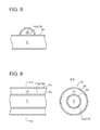
- FIG. 8 is a schematic cross-sectional view illustrating an example of a heating unit of the third embodiment.
- FIG. 9 is a schematic cross-sectional view illustrating another example of a heating unit of the third embodiment.
- FIG. 10 is an overall configuration diagram of an engine system including an intake bypass device according to the fourth embodiment of the present invention.
- FIG. 11 is a schematic cross-sectional view illustrating an example of a heating unit of the fourth embodiment.
- FIG. 12 is a schematic cross-sectional view illustrating another example of a heating unit of the fourth embodiment.
- FIG. 1 is an overall configuration diagram of an engine system including an intake bypass device according to the first embodiment of the present invention.
- the engine system 1 of the present embodiment at least includes an engine body 2 , an intake channel 4 for supplying intake air to cylinders 2 a of the engine body 2 , an exhaust channel 6 for carrying exhaust gas discharged from the cylinders 2 a of the engine body 2 , a turbocharger 12 for compressing intake air to be supplied to the engine body 2 , and an intake bypass device 20 for guiding a part of the compressed intake air compressed by the turbocharger 12 to the exhaust channel 6 bypassing the engine body 2 .
- the engine body 2 includes a plurality of cylinders 2 a .
- the engine body 2 and the intake channel 4 are connected to each other via an intake manifold 5 , and the intake manifold 5 distributes the intake air flowing through the intake channel 4 to each of the plurality of cylinders 2 a .
- the engine body 2 and the exhaust channel 6 are connected to each other via an exhaust manifold 7 , and the exhaust manifold 7 collects the exhaust air discharged from the plurality of cylinders 2 a into the exhaust channel 6 .
- the turbocharger 12 includes a turbine 8 disposed in the exhaust channel 6 , and a compressor 10 disposed in the intake channel 4 and coupled to the turbine 8 via a rotor to be driven coaxially with the turbine 8 .
- the turbine 8 is driven by exhaust energy of the exhaust gas discharged from the engine body 2 , and thereby the compressor 10 is coaxially driven, so as to compress the intake air flowing through the intake channel 4 .
- an airflow meter 31 for measuring an intake flow rate is disposed on the upstream side of the compressor 10 of the intake channel 4 . Further, on the downstream side of the compressor 10 of the intake channel 4 , a pressure sensor 33 for measuring a boost pressure of the compressed intake air is disposed.
- the intake bypass device 20 includes a bypass channel 14 connecting the downstream side of the compressor 10 in the intake channel 4 and the upstream side of the turbine 8 in the exhaust channel 6 , a bypass valve 16 disposed in the bypass channel 14 , and a heating unit 18 for heating the compressed intake air flowing through the bypass channel 14 .
- the bypass valve 16 of the present embodiment is configured as a flow-rate control valve for controlling the flow rate of the compressed intake air guided to flow to the exhaust channel 6 from the intake channel 4 .
- the valve opening degree of the bypass valve 16 is controlled by a turbo ECU (turbo control unit) 24 described below, so that surging does not occur in the compressor 10 .
- the type of the bypass valve 16 is not limited to a flow-rate control valve. It is sufficient if the bypass valve 16 can at least prevent a backward flow of the exhaust gas from the exhaust channel 6 to the intake channel 4 , and the bypass valve 16 may be a check valve or the like.
- FIG. 2 is a compressor map showing the operation characteristics of a compressor.
- x-axis is the flow rate and y-axis is the pressure ratio of the pressure at the inlet to that at the outlet of the compressor 10 .
- the reference signs N 1 , N 2 , N 3 in the drawing each represent the rotation speed of the compressor.
- the operating point P 1 may shift to the left side of the surge line to enter the surge region.
- the operating point (operation line) of the compressor 10 entering the surge region represents occurrence of surging in the compressor 10 .
- the bypass valve 16 is controlled to have a large valve-opening degree, to increase the flow rate of the compressed intake air guided to flow to the exhaust channel 6 from the intake channel 4 .
- the turbine output increases and the operation flow rate of the compressor 10 increases (Q 1 to Q 2 ), and thereby the operation point P 2 shifts out of the surge region.
- surging is prevented.
- FIG. 3 is a block diagram for describing the function of a turbo ECU.
- the turbo ECU 24 is a control unit independent from an engine electronic control unit (ECU) 22 for controlling the operation state of the engine body 2 , and includes a control part 24 B and a signal input part 24 A separate and independent from the engine ECU 22 .
- the turbo ECU 24 and the engine ECU 22 are configured as a microcomputer including a central processing unit (CPU), a random access memory (RAM), a read only memory (ROM), and an I/O interface.
- the turbo ECU 24 includes the signal input part 24 A, the turbo control part 24 B, and a signal output part 24 C.
- signals related to an intake flow rate measured by the airflow meter 31 and a boost pressure measured by the pressure sensor 33 are inputted.
- the turbo control part 24 B includes an operation-point computing part 24 B 1 and a bypass-valve control part 24 B 2 .
- the operation-point computing part 24 B 1 computes the operation point of the compressor 10 from the compressor map illustrated in FIG. 2 , from the intake flow rate and the boost pressure inputted into the signal input part 24 A.
- the bypass-valve control part 24 B 2 generates a bypass-valve opening degree command value such that increases the valve opening degree of the bypass valve 16 , when the operation point computed by the operation-point computing part 24 B 1 is in the vicinity of the surge region.
- the signal related to the generated bypass-valve opening degree command value is outputted to the bypass valve 16 from the signal output part 24 C, and thereby the valve opening degree of the bypass valve 16 is controlled.
- the control logic and hardware configuration of the engine ECU 22 have become increasingly complicated.
- the bypass-valve control part 24 B 2 for controlling the valve opening degree of the bypass valve 16 is mounted to the engine ECU 22 , the control logic and hardware configuration of the engine ECU 22 would become even more complicated.
- communication delay of the engine ECU may be a problem.
- the turbo ECU 24 itself computes the operation point of the compressor 10 and controls the valve opening degree of the bypass valve 16 on the basis of the computed operation point, it is possible to control the bypass valve 16 quickly while avoiding an influence of communication delay as compared to a case where the engine ECU 22 controls the valve opening degree of the bypass valve 16 .
- the heating unit 18 is to heat the compressed intake air flowing through the bypass channel 14 .
- a heater may be provided, for instance, to be used as a heat source, or exhaust gas discharged from the engine body 2 may be used as a heat source as in the embodiments described below.
- the intake bypass device 20 includes the heating unit 18 for heating the compressed intake air flowing through the bypass channel 14 , and is configured so that the compressed intake air having been heated is guided to flow to the upstream side of the turbine 8 .
- FIG. 4 is an overall configuration diagram of an engine system including an intake bypass device according to the second embodiment of the present invention.
- the engine system 1 a of the present embodiment basically has a similar configuration to that of the engine system 1 of the above described embodiment, except for the above described heating unit 18 .
- the same components are associated with the same reference numerals and not described in detail.
- FIG. 5 is a schematic cross-sectional view illustrating an example of a heating unit of the second embodiment.
- the heating unit 18 of the embodiment illustrated in FIGS. 5A and 5B is constituted by a turbine housing 8 A of the turbine 8 forming at least a part of an inner wall surface of the bypass channel 14 , at least in a partial section of the bypass channel 14 .
- a part of an outer wall surface of a scroll portion 8 a forming a scroll channel 8 d forms a part of the inner wall surface of the bypass channel 14 .
- the part of the outer wall surface of the scroll portion 8 a indicated by the reference numeral 14 a in the drawing corresponds to the heating unit 18 of the present embodiment.
- a through hole formed inside a shroud portion 8 e of the turbine housing 8 A constitutes the bypass channel 14
- an inner section of the shroud portion 8 e of the turbine housing 8 A forms the inner wall surface of the bypass channel 14 .
- the entire inner wall surface indicated by the reference numeral 14 a in the drawing corresponds to the heating unit 18 of the present embodiment.
- the reference numeral 8 b indicates a hub
- 8 c indicates an impeller
- 9 indicates a bearing housing.
- FIG. 6 is a schematic cross-sectional view illustrating another example of a heating unit of the second embodiment.
- a part of the turbine housing 8 A has a dual structure including an inner housing 8 A 1 formed of sheet metal forming the scroll channel 8 d and an outer housing 8 A 2 formed of sheet metal covering the inner housing 8 A 1 .
- the space defined by the inner housing 8 A 1 and the outer housing 8 A 2 forms a partial section of the above described bypass channel 14 .
- an outer wall surface of the inner housing 8 A 1 forms a part of the inner wall surface of the bypass channel 14
- the outer wall surface (indicated by the reference numeral 14 a in the drawing) of the inner housing 8 A 1 corresponds to the heating unit 18 of the present embodiment.
- the space defined by the inner housing 8 A 1 and the outer housing 8 A 2 constitutes a partial section of the above described bypass channel, and the compressed intake air flows through this space, which makes it possible to heat the compressed intake air and cool the turbine housing 8 A efficiently.
- FIG. 7 is an overall configuration diagram of an engine system including an intake bypass device according to the third embodiment of the present invention.
- the engine system 1 b of the present embodiment further includes an exhaust-gas purification device 26 for purifying exhaust gas discharged from the engine body 2 .
- the exhaust-gas purification device 26 is disposed on the downstream side of the turbine 8 in the exhaust channel 6 .
- the above described heating unit 18 is disposed on the downstream side of the exhaust-gas purification device 26 .
- the engine system 1 b of the present embodiment has a similar configuration to that of the above described embodiment, and thus the same components are associated with the same reference numerals and not described in detail.
- FIG. 8 is a schematic cross-sectional view illustrating an example of a heating unit of the third embodiment.
- the heating unit 18 of the embodiment illustrated in FIG. 8 is constituted by a part of an outer surface of an exhaust duct 6 a of the exhaust channel 6 at the downstream side of the exhaust-gas purification device 26 forming at least a part of the inner wall surface of the bypass channel 14 , in a partial section of the bypass channel 14 .
- the part of the outer surface of the exhaust duct 6 a indicated by the reference numeral 14 a in the drawing corresponds to the heating unit 18 of the present embodiment.
- FIG. 9 is a schematic cross-sectional view illustrating another example of a heating unit of the third embodiment.
- the exhaust channel 6 at the downstream side of the exhaust-gas purification device 26 has a dual structure including an inner exhaust duct 6 b through which the exhaust gas flows and an outer exhaust duct 6 c covering the inner exhaust duct.
- the space defined by the inner exhaust duct 6 b and the outer exhaust duct 6 c forms a partial section of the above described bypass channel 14 .
- an outer surface of the inner exhaust duct 6 b forms a part of the inner wall surface of the bypass channel 14 , and the outer surface (indicated by the reference numeral 14 a in the drawing) of the inner exhaust duct 6 b corresponds to the heating unit 18 of the present embodiment.
- the space defined by the inner exhaust duct 6 b and the outer exhaust duct 6 c constitutes a partial section of the above described bypass channel, and the compressed intake air flows through this space, which makes it possible to heat the compressed intake air efficiently.
- FIG. 10 is an overall configuration diagram of an engine system including an intake bypass device according to the fourth embodiment of the present invention.
- the engine system 1 c of the present embodiment basically has a similar configuration to that of the engine system 1 of the above described embodiment, except for the above described heating unit 18 .
- the same components are associated with the same reference numerals and not described in detail.
- FIG. 11 is a schematic cross-sectional view illustrating an example of a heating unit of the fourth embodiment.
- the heating unit 18 of the embodiment illustrated in FIG. 11 is constituted by a part of an outer wall surface of an exhaust manifold 7 forming a part of the inner wall surface of the bypass channel 14 , in a partial section of the bypass channel 14 .
- the part of the outer surface of the exhaust manifold 7 indicated by the reference numeral 14 a in the drawing corresponds to the heating unit 18 of the present embodiment.
- FIG. 12 is a schematic cross-sectional view illustrating another example of a heating unit of the fourth embodiment.
- the exhaust manifold 7 has a dual structure including an inner exhaust manifold 7 a through which the exhaust gas flows and an outer exhaust manifold 7 b covering the inner exhaust manifold 7 a .
- the space defined by the inner exhaust manifold 7 a and the outer exhaust manifold 7 b forms a partial section of the above described bypass channel 14 .
- an outer surface of the inner exhaust manifold 7 a forms a part of the inner wall surface of the bypass channel 14
- the outer surface (indicated by the reference numeral 14 a in the drawing) of the inner exhaust manifold 7 a corresponds to the heating unit 18 of the present embodiment.
- the space defined by the inner exhaust manifold 7 a and the outer exhaust manifold 7 b constitutes a partial section of the above described bypass channel 14 , and the compressed intake air flows through this space, which makes it possible to heat the compressed intake air and cool the exhaust manifold 7 efficiently.
- At least one embodiment of the present invention can be suitably used in an engine including a turbocharger for not only automobiles but also for ships and other industrial usages.
Landscapes
- Engineering & Computer Science (AREA)
- Chemical & Material Sciences (AREA)
- Mechanical Engineering (AREA)
- General Engineering & Computer Science (AREA)
- Combustion & Propulsion (AREA)
- Chemical Kinetics & Catalysis (AREA)
- Health & Medical Sciences (AREA)
- Toxicology (AREA)
- Sustainable Development (AREA)
- Life Sciences & Earth Sciences (AREA)
- Physics & Mathematics (AREA)
- Fluid Mechanics (AREA)
- General Chemical & Material Sciences (AREA)
- Computer Hardware Design (AREA)
- Microelectronics & Electronic Packaging (AREA)
- Supercharger (AREA)
Applications Claiming Priority (1)
| Application Number | Priority Date | Filing Date | Title |
|---|---|---|---|
| PCT/JP2013/077786 WO2015052837A1 (ja) | 2013-10-11 | 2013-10-11 | 吸気バイパス装置を備えたエンジンシステム |
Publications (2)
| Publication Number | Publication Date |
|---|---|
| US20160215712A1 US20160215712A1 (en) | 2016-07-28 |
| US9797320B2 true US9797320B2 (en) | 2017-10-24 |
Family
ID=52812684
Family Applications (1)
| Application Number | Title | Priority Date | Filing Date |
|---|---|---|---|
| US14/911,591 Expired - Fee Related US9797320B2 (en) | 2013-10-11 | 2013-10-11 | Engine system with intake bypass device |
Country Status (5)
| Country | Link |
|---|---|
| US (1) | US9797320B2 (de) |
| EP (1) | EP3020939B1 (de) |
| JP (1) | JP6072277B2 (de) |
| CN (1) | CN105324558B (de) |
| WO (1) | WO2015052837A1 (de) |
Families Citing this family (13)
| Publication number | Priority date | Publication date | Assignee | Title |
|---|---|---|---|---|
| EP3121432B1 (de) * | 2014-03-20 | 2019-08-07 | Nissan Motor Co., Ltd | Steuerungsvorrichtung und steuerungsverfahren für dieselmotor |
| FR3035443B1 (fr) * | 2015-04-21 | 2017-04-21 | Ifp Energies Now | Dispositif ameliore de controle de la quantite d'air introduit a l'admission d'un moteur a combustion interne suralimente et procede utilisant un tel dispositif |
| DK178780B1 (en) * | 2015-06-19 | 2017-01-23 | Man Diesel & Turbo Filial Af Man Diesel & Turbo Se Tyskland | Large two-stroke turbocharged compression ignited internal combustion engine with an exhaust gas purification system |
| EP3176397A1 (de) * | 2015-12-04 | 2017-06-07 | Winterthur Gas & Diesel Ltd. | Verbrennungsmotor und verfahren zum optimieren der abgasnachbehandlung eines verbrennungsmotors |
| EP3176396A1 (de) * | 2015-12-04 | 2017-06-07 | Winterthur Gas & Diesel Ltd. | Verbrennungsmotor und verfahren zum optimieren eine abgasnachbehandlung |
| FR3051225B1 (fr) * | 2016-05-11 | 2019-09-13 | IFP Energies Nouvelles | Methode de controle de la quantite d'air introduit a l'admission d'un moteur a combustion interne suralimente par un turbocompresseur a simple entree |
| DK201670345A1 (en) * | 2016-05-24 | 2017-12-11 | Man Diesel & Turbo Filial Af Man Diesel & Turbo Se Tyskland | Method for operating a two-stroke engine system |
| US10934979B2 (en) * | 2017-05-30 | 2021-03-02 | Ford Global Technologies, Llc | Methods and system diagnosing a variable geometry compressor for an internal combustion engine |
| AT522942A2 (de) * | 2019-12-16 | 2021-03-15 | Avl List Gmbh | Brennkraftmaschine |
| DE102020004716B8 (de) * | 2020-08-05 | 2022-06-09 | Mercedes-Benz Group AG | Verbrennungskraftmaschine für ein Kraftfahrzeug sowie Kraftfahrzeug |
| CN114233473B (zh) * | 2021-09-19 | 2025-04-29 | 江鹏 | 一种发动机进气旁通装置 |
| CN114458440B (zh) * | 2021-12-28 | 2023-04-25 | 中国北方发动机研究所(天津) | 一种交叉补燃废气涡轮增压系统 |
| GB2629424A (en) * | 2023-04-28 | 2024-10-30 | Jaguar Land Rover Ltd | Turbomachine housing with heating system inlet and valve |
Citations (26)
| Publication number | Priority date | Publication date | Assignee | Title |
|---|---|---|---|---|
| US3796046A (en) | 1970-05-02 | 1974-03-12 | Kuehnle Kopp Kausch Ag | Process for detoxicating exhaust gases from otto-combustion engines and apparatus for carrying out such process |
| US4122673A (en) * | 1973-09-28 | 1978-10-31 | J. Eberspacher | Internal combustion engine with afterburning and catalytic reaction in a supercharger turbine casing |
| US4404805A (en) * | 1980-03-21 | 1983-09-20 | Societe D'etudes De Machines Thermiques S.E.M.T. | Method of and system for power generation by supercharged internal combustion engine |
| JPS63314320A (ja) | 1987-06-16 | 1988-12-22 | Yamaha Motor Co Ltd | タ−ボ過給式エンジン |
| DE3818230A1 (de) | 1988-05-28 | 1989-12-07 | Johann Wimmer | Aggregat zur steigerung des ladedruckes an aufgeladenen verbrennungsmotoren, im teillast- und unteren drehzahlbereich |
| JPH10281017A (ja) | 1997-03-31 | 1998-10-20 | Caterpillar Inc | 内燃エンジンの排気ガス再循環システム |
| JP2921434B2 (ja) * | 1995-03-24 | 1999-07-19 | トヨタ自動車株式会社 | 車両用縦置き式エンジンの冷却構造 |
| US5987885A (en) | 1998-01-29 | 1999-11-23 | Chrysler Corporation | Combination catalytic converter and heat exchanger that maintains a catalyst substrate within an efficient operating temperature range for emmisions reduction |
| JP2000064844A (ja) | 1998-08-12 | 2000-02-29 | Mitsubishi Heavy Ind Ltd | 内燃機関の過給装置 |
| US6358109B1 (en) * | 1999-12-08 | 2002-03-19 | Bombardier Motor Corporation Of America | Air cooled marine engine exhaust |
| US6637204B2 (en) * | 2000-12-14 | 2003-10-28 | Siemens Aktiengesellschaft | Device and method for the heating of a catalytic converter for a supercharged internal combustion engine |
| JP2004346776A (ja) | 2003-05-20 | 2004-12-09 | Komatsu Ltd | 給気バイパス制御装置を備えた内燃機関 |
| JP2005188351A (ja) | 2003-12-25 | 2005-07-14 | Honda Motor Co Ltd | 排気マニホールド一体型エンジンの冷却構造 |
| US20060064981A1 (en) * | 2004-09-29 | 2006-03-30 | Mitsubishi Jidosha Kogyo Kabushiki Kaisha | Internal combustion engine having supercharger |
| US20070034195A1 (en) * | 2005-05-25 | 2007-02-15 | Jan-Erik Wijk | Control unit, supercharging system, vehicle comprising a supercharging system and method of controlling a supercharging system |
| JP2007085266A (ja) | 2005-09-22 | 2007-04-05 | Toyota Motor Corp | 排気系熱交換装置 |
| JP2007162545A (ja) | 2005-12-13 | 2007-06-28 | Isuzu Motors Ltd | エンジンの過給器システム |
| US20070289954A1 (en) * | 2004-02-25 | 2007-12-20 | Daimlerchrysler Ag,Borgwarner Turbo Systems Ag | Method for Connecting a Sheet Metal Component, Such as a Pipe, to a Cast Metal Component, Such as a Housing Port, in Particular for an Exhaust System |
| JP2008151006A (ja) | 2006-12-15 | 2008-07-03 | Toyota Motor Corp | ターボチャージャの制御装置 |
| JP2008190503A (ja) | 2007-02-07 | 2008-08-21 | Toyota Motor Corp | 内燃機関のシリンダヘッド |
| JP2010038201A (ja) | 2008-08-01 | 2010-02-18 | Aisan Ind Co Ltd | 中空流体通路部品及びその製造方法 |
| US20110138774A1 (en) * | 2010-06-03 | 2011-06-16 | Ford Global Technologies, Llc | Intake air heating and exhaust cooling |
| US20120117962A1 (en) * | 2009-07-24 | 2012-05-17 | Vandyne Ed | Rich fuel mixture super-turbocharged engine system |
| JP2012159079A (ja) | 2011-01-31 | 2012-08-23 | Man Diesel & Turbo Filial Af Man Diesel & Turbo Se Tyskland | 排気ガス再循環を用いた大型ターボチャージャ搭載2ストローク・ディーゼル・エンジン |
| WO2013118410A1 (ja) | 2012-02-08 | 2013-08-15 | トヨタ自動車株式会社 | 内燃機関の冷却装置 |
| US8627662B2 (en) * | 2011-10-19 | 2014-01-14 | General Electric Company | Exhaust gas recirculation heat recovery system and method |
Family Cites Families (1)
| Publication number | Priority date | Publication date | Assignee | Title |
|---|---|---|---|---|
| US6990814B2 (en) * | 2003-12-18 | 2006-01-31 | Caterpillar Inc. | Engine turbocharger control management system |
-
2013
- 2013-10-11 EP EP13895188.4A patent/EP3020939B1/de active Active
- 2013-10-11 CN CN201380077737.7A patent/CN105324558B/zh not_active Expired - Fee Related
- 2013-10-11 JP JP2015541405A patent/JP6072277B2/ja not_active Expired - Fee Related
- 2013-10-11 US US14/911,591 patent/US9797320B2/en not_active Expired - Fee Related
- 2013-10-11 WO PCT/JP2013/077786 patent/WO2015052837A1/ja not_active Ceased
Patent Citations (29)
| Publication number | Priority date | Publication date | Assignee | Title |
|---|---|---|---|---|
| US3796046A (en) | 1970-05-02 | 1974-03-12 | Kuehnle Kopp Kausch Ag | Process for detoxicating exhaust gases from otto-combustion engines and apparatus for carrying out such process |
| US4122673A (en) * | 1973-09-28 | 1978-10-31 | J. Eberspacher | Internal combustion engine with afterburning and catalytic reaction in a supercharger turbine casing |
| US4404805A (en) * | 1980-03-21 | 1983-09-20 | Societe D'etudes De Machines Thermiques S.E.M.T. | Method of and system for power generation by supercharged internal combustion engine |
| JPS63314320A (ja) | 1987-06-16 | 1988-12-22 | Yamaha Motor Co Ltd | タ−ボ過給式エンジン |
| DE3818230A1 (de) | 1988-05-28 | 1989-12-07 | Johann Wimmer | Aggregat zur steigerung des ladedruckes an aufgeladenen verbrennungsmotoren, im teillast- und unteren drehzahlbereich |
| JP2921434B2 (ja) * | 1995-03-24 | 1999-07-19 | トヨタ自動車株式会社 | 車両用縦置き式エンジンの冷却構造 |
| US6038860A (en) | 1997-03-31 | 2000-03-21 | Caterpillar Inc. | Exhaust gas recirculation method for an internal combustion engine |
| JPH10281017A (ja) | 1997-03-31 | 1998-10-20 | Caterpillar Inc | 内燃エンジンの排気ガス再循環システム |
| US5987885A (en) | 1998-01-29 | 1999-11-23 | Chrysler Corporation | Combination catalytic converter and heat exchanger that maintains a catalyst substrate within an efficient operating temperature range for emmisions reduction |
| JP2000064844A (ja) | 1998-08-12 | 2000-02-29 | Mitsubishi Heavy Ind Ltd | 内燃機関の過給装置 |
| US6358109B1 (en) * | 1999-12-08 | 2002-03-19 | Bombardier Motor Corporation Of America | Air cooled marine engine exhaust |
| US6637204B2 (en) * | 2000-12-14 | 2003-10-28 | Siemens Aktiengesellschaft | Device and method for the heating of a catalytic converter for a supercharged internal combustion engine |
| JP2004346776A (ja) | 2003-05-20 | 2004-12-09 | Komatsu Ltd | 給気バイパス制御装置を備えた内燃機関 |
| US7032382B2 (en) * | 2003-05-20 | 2006-04-25 | Komatsu Ltd. | Internal combustion engine provided with intake bypass control device |
| JP2005188351A (ja) | 2003-12-25 | 2005-07-14 | Honda Motor Co Ltd | 排気マニホールド一体型エンジンの冷却構造 |
| US20070289954A1 (en) * | 2004-02-25 | 2007-12-20 | Daimlerchrysler Ag,Borgwarner Turbo Systems Ag | Method for Connecting a Sheet Metal Component, Such as a Pipe, to a Cast Metal Component, Such as a Housing Port, in Particular for an Exhaust System |
| US20060064981A1 (en) * | 2004-09-29 | 2006-03-30 | Mitsubishi Jidosha Kogyo Kabushiki Kaisha | Internal combustion engine having supercharger |
| US20070034195A1 (en) * | 2005-05-25 | 2007-02-15 | Jan-Erik Wijk | Control unit, supercharging system, vehicle comprising a supercharging system and method of controlling a supercharging system |
| JP2007085266A (ja) | 2005-09-22 | 2007-04-05 | Toyota Motor Corp | 排気系熱交換装置 |
| JP2007162545A (ja) | 2005-12-13 | 2007-06-28 | Isuzu Motors Ltd | エンジンの過給器システム |
| JP2008151006A (ja) | 2006-12-15 | 2008-07-03 | Toyota Motor Corp | ターボチャージャの制御装置 |
| JP2008190503A (ja) | 2007-02-07 | 2008-08-21 | Toyota Motor Corp | 内燃機関のシリンダヘッド |
| US20100095671A1 (en) | 2007-02-07 | 2010-04-22 | Hajime Takagawa | Cylinder head of internal-combustion engine |
| JP2010038201A (ja) | 2008-08-01 | 2010-02-18 | Aisan Ind Co Ltd | 中空流体通路部品及びその製造方法 |
| US20120117962A1 (en) * | 2009-07-24 | 2012-05-17 | Vandyne Ed | Rich fuel mixture super-turbocharged engine system |
| US20110138774A1 (en) * | 2010-06-03 | 2011-06-16 | Ford Global Technologies, Llc | Intake air heating and exhaust cooling |
| JP2012159079A (ja) | 2011-01-31 | 2012-08-23 | Man Diesel & Turbo Filial Af Man Diesel & Turbo Se Tyskland | 排気ガス再循環を用いた大型ターボチャージャ搭載2ストローク・ディーゼル・エンジン |
| US8627662B2 (en) * | 2011-10-19 | 2014-01-14 | General Electric Company | Exhaust gas recirculation heat recovery system and method |
| WO2013118410A1 (ja) | 2012-02-08 | 2013-08-15 | トヨタ自動車株式会社 | 内燃機関の冷却装置 |
Non-Patent Citations (6)
| Title |
|---|
| Chinese Office and Search Report, dated Apr. 19, 2017, for corresponding Chinese Application No. 201380077737.7, with English translation of the Office Action only. |
| Extended European Search Report dated Sep. 22, 2016 in the corresponding European Application No. 13895188.4. |
| International Preliminary Report on Patentability and Written Opinion of the International Searching Authority (Forms PCT/IB/338, PCT/IB/373, PCT/IB/326 and PCT/ISA/237), dated Apr. 21, 2016, for International Application No. PCT/JP2013/077786, with an English translation of the Written Opinion. |
| International Search Report (Forms PCT/ISA/220 and PCT/ISA/210), dated Dec. 3, 2013, for International Application No. PCT/JP2013/077786. |
| Japanese Decision to Grant a Patent, dated Dec. 2, 2016, for Japanese Application No. 2015-541405, along with an English translation. |
| Machine generated translation of DE3818230A1 obtained on Apr. 25, 2017 from https://worldwide.espacenet.com/. * |
Also Published As
| Publication number | Publication date |
|---|---|
| CN105324558B (zh) | 2018-10-09 |
| EP3020939A4 (de) | 2016-10-26 |
| EP3020939A1 (de) | 2016-05-18 |
| JP6072277B2 (ja) | 2017-02-01 |
| US20160215712A1 (en) | 2016-07-28 |
| WO2015052837A1 (ja) | 2015-04-16 |
| EP3020939B1 (de) | 2019-12-04 |
| CN105324558A (zh) | 2016-02-10 |
| JPWO2015052837A1 (ja) | 2017-03-09 |
Similar Documents
| Publication | Publication Date | Title |
|---|---|---|
| US9797320B2 (en) | Engine system with intake bypass device | |
| JP5853403B2 (ja) | 内燃機関の制御装置 | |
| CN105822379B (zh) | 发动机制动装置和用于操作发动机制动装置的方法 | |
| CN101675223A (zh) | 控制涡轮增压器的方法 | |
| CN103930656A (zh) | 窜气换气装置 | |
| WO2009111223A2 (en) | Multi-stage turbocharging system with thermal bypass | |
| CN103644024A (zh) | 一种汽车发动机进气温度调节系统 | |
| JP2013515207A (ja) | 内燃機関 | |
| JPWO2014207831A1 (ja) | 内燃機関の排気再循環装置 | |
| US20120152214A1 (en) | Turbocharger system | |
| CN105705745B (zh) | 排气结构 | |
| CN103195555B (zh) | 用于超涡轮增压发动机的控制系统和方法 | |
| JP5538712B2 (ja) | 内燃機関のegr装置 | |
| KR101472910B1 (ko) | 볼텍스 튜브를 이용한 흡입공기 냉각장치 | |
| JP2013047523A (ja) | プレッシャウェーブスーパーチャージャを備えた内燃機関における過給圧調整方法 | |
| CN102220896A (zh) | 增压内燃机进气的装置、交通工具和增压内燃机进气的方法 | |
| JP5964260B2 (ja) | エンジンの排ガスエネルギー回収装置 | |
| US10533490B2 (en) | Supercharging system of internal combustion engine and method of controlling supercharging system | |
| EP3022431B1 (de) | Aspirator und ejektorsystem für eine brennkraftmaschine | |
| WO2014161558A1 (en) | Method and apparatus for controlling an engine with egr and a turbocharger | |
| KR101513587B1 (ko) | 볼텍스 튜브를 이용하는 유로가변형 흡입공기 냉각장치 및 그 제어방법 | |
| JP4816514B2 (ja) | 過給機付内燃機関 | |
| JP6077485B2 (ja) | エンジン | |
| JP5067268B2 (ja) | 過給機付きエンジンの過給圧制御装置 | |
| JP2017120068A (ja) | 廃熱回収装置 |
Legal Events
| Date | Code | Title | Description |
|---|---|---|---|
| AS | Assignment |
Owner name: MITSUBISHI HEAVY INDUSTRIES, LTD., JAPAN Free format text: ASSIGNMENT OF ASSIGNORS INTEREST;ASSIGNORS:YOKOYAMA, TAKAO;IBARAKI, SEIICHI;TOMITA, ISAO;AND OTHERS;REEL/FRAME:037777/0129 Effective date: 20160215 |
|
| STCF | Information on status: patent grant |
Free format text: PATENTED CASE |
|
| MAFP | Maintenance fee payment |
Free format text: PAYMENT OF MAINTENANCE FEE, 4TH YEAR, LARGE ENTITY (ORIGINAL EVENT CODE: M1551); ENTITY STATUS OF PATENT OWNER: LARGE ENTITY Year of fee payment: 4 |
|
| FEPP | Fee payment procedure |
Free format text: MAINTENANCE FEE REMINDER MAILED (ORIGINAL EVENT CODE: REM.); ENTITY STATUS OF PATENT OWNER: LARGE ENTITY |
|
| LAPS | Lapse for failure to pay maintenance fees |
Free format text: PATENT EXPIRED FOR FAILURE TO PAY MAINTENANCE FEES (ORIGINAL EVENT CODE: EXP.); ENTITY STATUS OF PATENT OWNER: LARGE ENTITY |
|
| STCH | Information on status: patent discontinuation |
Free format text: PATENT EXPIRED DUE TO NONPAYMENT OF MAINTENANCE FEES UNDER 37 CFR 1.362 |
|
| FP | Lapsed due to failure to pay maintenance fee |
Effective date: 20251024 |