EP3020955B1 - Dichtungsvorrichtung - Google Patents
Dichtungsvorrichtung Download PDFInfo
- Publication number
- EP3020955B1 EP3020955B1 EP14823700.1A EP14823700A EP3020955B1 EP 3020955 B1 EP3020955 B1 EP 3020955B1 EP 14823700 A EP14823700 A EP 14823700A EP 3020955 B1 EP3020955 B1 EP 3020955B1
- Authority
- EP
- European Patent Office
- Prior art keywords
- pipe
- intake
- flow
- noise reduction
- sealing device
- Prior art date
- Legal status (The legal status is an assumption and is not a legal conclusion. Google has not performed a legal analysis and makes no representation as to the accuracy of the status listed.)
- Active
Links
Images



Classifications
-
- F—MECHANICAL ENGINEERING; LIGHTING; HEATING; WEAPONS; BLASTING
- F02—COMBUSTION ENGINES; HOT-GAS OR COMBUSTION-PRODUCT ENGINE PLANTS
- F02M—SUPPLYING COMBUSTION ENGINES IN GENERAL WITH COMBUSTIBLE MIXTURES OR CONSTITUENTS THEREOF
- F02M35/00—Combustion-air cleaners, air intakes, intake silencers, or induction systems specially adapted for, or arranged on, internal-combustion engines
- F02M35/12—Intake silencers ; Sound modulation, transmission or amplification
- F02M35/1205—Flow throttling or guiding
- F02M35/1211—Flow throttling or guiding by using inserts in the air intake flow path, e.g. baffles, throttles or orifices; Flow guides
-
- F—MECHANICAL ENGINEERING; LIGHTING; HEATING; WEAPONS; BLASTING
- F02—COMBUSTION ENGINES; HOT-GAS OR COMBUSTION-PRODUCT ENGINE PLANTS
- F02F—CYLINDERS, PISTONS OR CASINGS, FOR COMBUSTION ENGINES; ARRANGEMENTS OF SEALINGS IN COMBUSTION ENGINES
- F02F11/00—Arrangements of sealings in combustion engines
-
- F—MECHANICAL ENGINEERING; LIGHTING; HEATING; WEAPONS; BLASTING
- F02—COMBUSTION ENGINES; HOT-GAS OR COMBUSTION-PRODUCT ENGINE PLANTS
- F02M—SUPPLYING COMBUSTION ENGINES IN GENERAL WITH COMBUSTIBLE MIXTURES OR CONSTITUENTS THEREOF
- F02M35/00—Combustion-air cleaners, air intakes, intake silencers, or induction systems specially adapted for, or arranged on, internal-combustion engines
- F02M35/10—Air intakes; Induction systems
- F02M35/10091—Air intakes; Induction systems characterised by details of intake ducts: shapes; connections; arrangements
-
- F—MECHANICAL ENGINEERING; LIGHTING; HEATING; WEAPONS; BLASTING
- F02—COMBUSTION ENGINES; HOT-GAS OR COMBUSTION-PRODUCT ENGINE PLANTS
- F02M—SUPPLYING COMBUSTION ENGINES IN GENERAL WITH COMBUSTIBLE MIXTURES OR CONSTITUENTS THEREOF
- F02M35/00—Combustion-air cleaners, air intakes, intake silencers, or induction systems specially adapted for, or arranged on, internal-combustion engines
- F02M35/10—Air intakes; Induction systems
- F02M35/10242—Devices or means connected to or integrated into air intakes; Air intakes combined with other engine or vehicle parts
- F02M35/10262—Flow guides, obstructions, deflectors or the like
-
- F—MECHANICAL ENGINEERING; LIGHTING; HEATING; WEAPONS; BLASTING
- F02—COMBUSTION ENGINES; HOT-GAS OR COMBUSTION-PRODUCT ENGINE PLANTS
- F02M—SUPPLYING COMBUSTION ENGINES IN GENERAL WITH COMBUSTIBLE MIXTURES OR CONSTITUENTS THEREOF
- F02M35/00—Combustion-air cleaners, air intakes, intake silencers, or induction systems specially adapted for, or arranged on, internal-combustion engines
- F02M35/12—Intake silencers ; Sound modulation, transmission or amplification
- F02M35/1205—Flow throttling or guiding
- F02M35/1216—Flow throttling or guiding by using a plurality of holes, slits, protrusions, perforations, ribs or the like; Surface structures; Turbulence generators
-
- F—MECHANICAL ENGINEERING; LIGHTING; HEATING; WEAPONS; BLASTING
- F02—COMBUSTION ENGINES; HOT-GAS OR COMBUSTION-PRODUCT ENGINE PLANTS
- F02M—SUPPLYING COMBUSTION ENGINES IN GENERAL WITH COMBUSTIBLE MIXTURES OR CONSTITUENTS THEREOF
- F02M35/00—Combustion-air cleaners, air intakes, intake silencers, or induction systems specially adapted for, or arranged on, internal-combustion engines
- F02M35/12—Intake silencers ; Sound modulation, transmission or amplification
- F02M35/1283—Manufacturing or assembly; Connectors; Fixations
-
- F—MECHANICAL ENGINEERING; LIGHTING; HEATING; WEAPONS; BLASTING
- F02—COMBUSTION ENGINES; HOT-GAS OR COMBUSTION-PRODUCT ENGINE PLANTS
- F02D—CONTROLLING COMBUSTION ENGINES
- F02D9/00—Controlling engines by throttling air or fuel-and-air induction conduits or exhaust conduits
- F02D9/08—Throttle valves specially adapted therefor; Arrangements of such valves in conduits
- F02D9/10—Throttle valves specially adapted therefor; Arrangements of such valves in conduits having pivotally-mounted flaps
- F02D9/1035—Details of the valve housing
- F02D9/104—Shaping of the flow path in the vicinity of the flap, e.g. having inserts in the housing
-
- F—MECHANICAL ENGINEERING; LIGHTING; HEATING; WEAPONS; BLASTING
- F02—COMBUSTION ENGINES; HOT-GAS OR COMBUSTION-PRODUCT ENGINE PLANTS
- F02M—SUPPLYING COMBUSTION ENGINES IN GENERAL WITH COMBUSTIBLE MIXTURES OR CONSTITUENTS THEREOF
- F02M29/00—Apparatus for re-atomising condensed fuel or homogenising fuel-air mixture
- F02M29/04—Apparatus for re-atomising condensed fuel or homogenising fuel-air mixture having screens, gratings, baffles or the like
-
- Y—GENERAL TAGGING OF NEW TECHNOLOGICAL DEVELOPMENTS; GENERAL TAGGING OF CROSS-SECTIONAL TECHNOLOGIES SPANNING OVER SEVERAL SECTIONS OF THE IPC; TECHNICAL SUBJECTS COVERED BY FORMER USPC CROSS-REFERENCE ART COLLECTIONS [XRACs] AND DIGESTS
- Y02—TECHNOLOGIES OR APPLICATIONS FOR MITIGATION OR ADAPTATION AGAINST CLIMATE CHANGE
- Y02T—CLIMATE CHANGE MITIGATION TECHNOLOGIES RELATED TO TRANSPORTATION
- Y02T10/00—Road transport of goods or passengers
- Y02T10/10—Internal combustion engine [ICE] based vehicles
- Y02T10/12—Improving ICE efficiencies
Definitions
- the present invention relates to a sealing device that is equipped in an intake pipe.
- a mounting groove for mounting the gasket is provided on an end surface of a member to be sealed, and the gasket is provided with a projection that makes close contact to a side surface of this mounting groove.
- Such a configuration makes it possible to stabilize the posture of the gasket in the mounting groove (see Patent Literature 4 and 5).
- Patent Literature 6 and Patent Literature 7 both disclose devices to be arranged in an intake air supply pipe for an internal combustion engine.
- Patent Literature 8 discloses a sealing device including an intake noise reduction portion according to the preamble of claim 1.
- Patent Literature 9 discloses a sealing device including a flow guiding net portion having concentric rings.
- An object of the present invention is to provide a sealing device that is capable of not only suppress the generation of unusual noise by guiding a gas flow but also suppressing the generation of unusual noise caused by resonance between the gas flow and a pipe, and that is superior in installation workability and ability to maintain posture of a gasket portion.
- the present invention employs the following means to solve the foregoing object.
- a sealing device is a sealing device according to claim 1 that includes a gasket portion made of an elastic body for sealing a space between an end surface of one of two pipes configuring an intake pipe and an end surface of another of the two pipes, and an intake noise reduction portion for reducing intake noise, wherein the intake noise reduction portion includes:
- the sealing device can exert not only a sealing function but also an intake noise reducing function.
- the position for disposing the main body portion in the intake pipe can be adjusted by setting the length of the tubular portion of the intake noise reduction portion. Therefore, a distance between a throttle valve and the main body portion can be adjusted, and the effect of reducing intake noise can sufficiently be exerted by disposing the main body portion in a position that produces a high intake noise reduction effect.
- the tubular portion of the intake noise reduction portion is fitted into the inner circumferential surface of either one of the two pipes configuring the intake pipe, the generation of unusual noise due to the resonance can be suppressed at this fitted portion.
- the tubular portion of the intake noise reduction portion is fitted into the inner circumferential surface of either one of the two pipes configuring the intake pipe, an installation of the sealing device to the intake pipe can be done with ease. Moreover, there is no need to provide a groove for mounting the gasket portion in the pipe in order to make the posture of the gasket portion stable.
- the sealing device according to claim 1 further includes an elastically deforming portion that is provided on an outer circumferential surface of the tubular portion, and is in close contact with an inner circumferential surface of either one of the one pipe and the other pipe thereby supporting the tubular portion in its positioned state within the pipe by an elastic repulsive force thereof.
- the sealing device can exert not only a sealing function but also an intake noise reducing function.
- the position for disposing the main body portion in the intake pipe can be adjusted by setting the length of the tubular portion of the intake noise reduction portion. Therefore, a distance between a throttle valve and the main body portion can be adjusted, and the effect of reducing intake noise can sufficiently be exerted by disposing the main body portion in a position that produces a high intake noise reduction effect.
- the elastically deforming portion is provided on the outer circumferential surface of the tubular portion of the intake noise reduction portion, and is in close contact with the inner circumferential surface of either one of the two pipes configuring the intake pipe, the generation of unusual noise due to the resonance can be suppressed at this close-contacting portion.
- tubular portion having the elastically deforming portion on its outer circumferential surface can be inserted into either one of the two pipes configuring the intake pipe, an installation of the sealing device to the intake pipe can be done with ease. Moreover, there is no need to provide a groove for mounting the gasket portion in the pipe in order to make the posture of the gasket portion stable.
- the main body portion may be configured from a flow-guiding net portion for guiding a gas flowing in the intake pipe.
- the main body portion may be configured from a plurality of suspended portions that are configured to sway in response to the gas flow.
- the gas flow will be dispersed due to the plurality of suspended portions.
- the damping performance of the rubber-like elastic body can damp the energy that generates noise. Owing to the combination of these effects, intake noise can be reduced effectively.
- the plurality of suspended portions deform in a direction of the gas flow in response to the gas flow, thereby suppressing the inflow resistance of the gas. Thus, the pressure loss of the gas to be suctioned does not increase.
- Each of the plurality of suspended portions may be provided with at least one through-hole.
- Such configuration can further lower the inflow resistance of the gas.
- the flow-guiding net portion may be configured such that a mesh thereof is fine in a vicinity of a center of a flow passage in the intake pipe and becomes coarser with distance from the vicinity of the center.
- the mesh of the flow-guiding net portion disposed on the lower side of the throttle valve is configured to be fine in the vicinity of the center of the flow passage in the intake pipe and to become coarser with distance from the vicinity of the center. Accordingly, since the air tends to flow through a coarse region within the mesh, the air flow is guided such that more air flows through the region within the intake pipe that is more distant from the vicinity of the center. Consequently, it is possible to suppress the merging of the air flows through the two places.
- the mesh of the flow-guiding net portion is formed of a plurality of radial portions extending radially outward from the vicinity of the center of the flow passage in the intake pipe and a plurality of concentric circular portions provided concentrically from the vicinity of the center.
- the "concentric circular portion" in the present invention includes not only a complete circular shape but also an arcuate shape such as a semicircle.
- the flow-guiding net portion in which the mesh is configured to be fine in the vicinity of the center of the flow passage in the intake pipe and to become coarser with distance from the vicinity of the center.
- the flow-guiding net portion in the case where the flow-guiding net portion is configured from an elastic material, the flow-guiding net portion elastically deforms due to the air flow.
- a shape obtained by projecting the flow-guiding net portion configured as described above in a direction of the air flow changes little between before and after the deformation. Therefore, the flow-guiding function is stably exhibited.
- the flow-guiding net portion is superior in durability.
- the present invention can provide a sealing device that is capable of not only suppressing the generation of unusual noise by guiding a gas flow but also suppressing the generation of unusual noise caused by resonance between the gas flow and a pipe, and that is superior in installation workability and ability to maintain posture of a gasket portion.
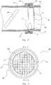
- FIG. 1 is a front view of a sealing device according to Example 1.
- Fig. 2 is a front view of an intake noise reduction portion according to Example 1. Specifically, Fig. 2 shows a state of the sealing device shown in Fig. 1 prior to be integrally molded with a gasket portion.
- Fig. 3 is a schematic cross-sectional view showing a state in which the sealing device according to Example 1 is attached to an intake pipe. Note that the view of the sealing device shown in Fig. 3 is a cross-sectional view taken along AA of Fig. 1 .
- a sealing device 100 according to the present example is equipped in an intake pipe provided to an intake manifold and the like. That is, the sealing device 100 according to the present example is equipped in a joint portion between two pipes configuring the intake pipe. For convenience of explanation, these two pipes are referred to hereinafter as the first pipe 210 and the second pipe 220.
- the sealing device 100 is disposed on a downstream side of a throttle valve 300 provided in the intake pipe in a direction of a gas flow.
- first pipe 210 and an end portion of the second pipe 220 are provided with flange portions 211, 221, respectively.
- the first pipe 210 and the second pipe 220 are coupled to each other by placing the flange portion 211 and the flange portion 221 on top of each other and fixing these flange portions with a known fixture (not shown) such as a bolt.
- the first pipe 210 and the second pipe 220 are each in a shape of a cylinder having a circular cross section perpendicular to the central axial line of an intake passage (a cross section perpendicular to a direction of extension of the pipes).
- axial direction denotes a direction of the central axial line of the intake passage.
- the sealing device 100 is provided integrally with a gasket portion 10 for sealing a space between an end surface of the first pipe 210 and an end surface of the second pipe 220, and an intake noise reduction portion 20 for reducing intake noise.
- the gasket portion 10 is composed from an elastic body (e.g., an elastomer such as rubber and TPE).
- the intake noise reduction portion 20 is configured from a flow-guiding net portion 21, an annular frame body portion 22 for supporting the flow-guiding net portion 21, a cylindrical portion 23 as a tubular portion, and a flange portion 24.
- the flow-guiding net portion 21 functions to guide a gas flowing inside the intake pipe and is provided over the entire region within the frame body portion 22 in the present example.
- the main body portion of the intake noise reduction portion 20 according to the present example is configured from the flow-guiding net portion 21 that guides the gas flowing inside the intake pipe.
- the cylindrical portion 23 extends in the direction in which the pipe extends from the frame body portion 22 (the axial direction), and is fitted into an inner circumferential surface of the second pipe 220.
- the outer diameter of the cylindrical portion 23 is set to be slightly larger than the inner diameter of the second pipe 220. Accordingly, the cylindrical portion 23 is fitted into the inner circumferential surface of the second pipe 220 by inserting the cylindrical portion 23 into the second pipe 220.
- the flange portion 24 extends from an end portion of the cylindrical portion 23 toward an outer circumferential surface side and is disposed in the space between the end surface of the first pipe 210 and the end surface of the second pipe 220.
- the gasket portions 10 are provided on both surfaces of the flange portion 24 in the intake noise reduction portion 20.
- each of the gasket portions 10 provided on both surfaces of the flange portion 24 seals the space between the end surface of the flange portion 211 of the first pipe 210 and the end surface of the flange portion 221 of the second pipe 220 by being sandwiched therebetween.
- the sealing device 100 that is formed integrally with the gasket portion 10 and the intake noise reduction portion 20 can be obtained by insert-molding the gasket portion 10 using the intake noise reduction portion 20 as an insert.
- the sealing device 100 can also be provided integrally with the gasket portion 10 and the intake noise reduction portion 20 by screen-printing the gasket portion 10 on both surfaces of the flange portion 24 in the intake noise reduction portion 20.
- the sealing device 100 can exert not only a sealing function but also an intake noise reducing function.
- the intake noise reduction portion 20 includes the flow-guiding net portion 21, it can suppress the generation of unusual noise by guiding the gas flow.
- the position for disposing the flow-guiding net portion 21 in the intake pipe can be adjusted by setting the length of the cylindrical portion 23 (the length in the axial direction) of the intake noise reduction portion 20. Consequently, the distance between the throttle valve 300 and the flow-guiding net portion 21 can be adjusted. Therefore, by disposing the flow-guiding net portion 21 in a position that produces a high intake noise reduction effect, the effect of reducing intake noise can sufficiently be exerted.
- the position of the flow-guiding net is determined in the position where the two pipes are coupled to each other, making it impossible to adjust the distance between the throttle valve and the flow-guiding net.
- the position of the flow-guiding net portion 21 can be adjusted as described above, thereby sufficiently exerting the effect of suppressing the generation of unusual noise by means of the flow-guiding net portion 21.
- the cylindrical portion 23 of the intake noise reduction portion 20 is fitted into the inner circumferential surface of the second pipe 220.
- the generation of unusual noise due to the resonance can be suppressed at this fitted portion.
- the sealing device 100 can be held stably with respect to the second pipe 220 by this fitted portion. Therefore, an installation of the sealing device 100 into the intake pipe can be done with ease.
- the sealing device 100 of the present example it is possible to not only suppress the generation of unusual noise by guiding the gas flow but also suppressing the generation of unusual noise caused by resonance between the gas flow and the pipe.
- the sealing device 100 is superior in installation workability.
- the sealing device 100 is superior in stability of the posture of the gasket portion 10.
- Comparative Example 2 is shown in Figs. 4 to 6 .
- Example 1 the configuration is described in which the tubular portion of the intake noise reduction portion is fitted into the inner circumferential surface of the pipe.
- Example 2 a configuration is described in which an elastically deforming portion is provided on the outer circumferential surface side of the tubular portion and this elastically deforming portion comes into close contact with the inner circumferential surface of the pipe.
- Other components and their effects are the same as those in Example 1, and hence the same components are denoted by the same reference numerals and the explanations thereof are omitted.
- the configuration is employed in which the tubular portion (the cylindrical portion 23) of the intake noise reduction portion 20 is fitted into the inner circumferential surface of the pipe (the second pipe 220). Accordingly, unless the dimensional accuracies of the outer diameter of the cylindrical portion 23 and the inner diameter of the second pipe 220 are set high, spaces that are created therebetween might cause backlash or might increase the fitting force applied to the cylindrical portion 23 while fitting too high. Particularly, in a case where the backlash is caused, it would cause unusual noise. In the present example, therefore, a configuration is described that is capable of resolving these problems.
- Fig. 4 is a front view of a sealing device according to comparative Example 2.
- Fig. 5 is a schematic perspective view of the sealing device according to Example 2. Note that Fig. 5 only shows one elastically deforming portion.
- Fig. 6 is a schematic cross-sectional view showing a state in which the sealing device according to Example 2 is attached to the intake pipe. Note that the view of the sealing device shown in Fig. 6 is a cross-sectional view taken along AA of Fig. 4 .
- the sealing device 100 according to the present example is equipped in an intake pipe provided to an intake manifold and the like.
- the configuration and the like of the intake pipe are those that have already been described in Example 1; thus, descriptions thereof are omitted accordingly.
- the sealing device 100 according to the present example is integrally provided with the gasket portion 10 for sealing the space between the end surface of the first pipe 210 and the end surface of the second pipe 220, and the intake noise reduction portion 20 for reducing intake noise.
- the gasket portion 10 is composed from an elastic body (e.g., an elastomer such as rubber and TPE).
- the intake noise reduction portion 20 is configured from a flow-guiding net portion 21, an annular frame body portion 22 for supporting the flow-guiding net portion 21, a cylindrical portion 23a as a tubular portion, an elastically deforming portion 25 provided on the outer circumferential surface side of the cylindrical portion 23a, and a flange portion 24. Since the flow-guiding net portion 21, the frame body portion 22, and the flange portion 24 have the same configurations as those described in Example 1; thus, descriptions thereof are omitted accordingly.
- the cylindrical portion 23a extends in the direction in which the pipe extends from the frame body portion 22 (the axial direction).
- an outer diameter of the cylindrical portion 23a is set to be smaller than an inner diameter of the second pipe 220. Accordingly, an annular space is formed between an outer circumferential surface of the cylindrical portion 23a and an inner circumferential surface of the second pipe 220.
- an elastically deforming portion 25 that is in close contact with the inner circumferential surface of the second pipe 220, and that supports the cylindrical portion 23a in its positioned state within the second pipe 220 by elastic repulsive force thereof.
- the elastically deforming portion 25 is provided in such a manner as to project toward the outer circumferential surface side of the cylindrical portion 23a.
- the elastically deforming portion 25 is provided at a total of four places that are equally spaced in a circumferential direction.
- the elastically deforming portion 25 is configured such that its portion on a flow-guiding net portion 21 side thereof is connected to the cylindrical portion 23a, it extends toward the flange portion 24 in the axial direction, and its end portion on a flange portion 24 side thereof is a free end. Accordingly, when inserting the cylindrical portion 23a into the second pipe 220, the free end of the elastically deforming portion 25 does not get caught by the inner circumferential surface of the second pipe 220, thereby enabling a smooth insertion.
- the gasket portion 10 is provided on both surfaces of the flange portion 24 in the intake noise reduction portion 20.
- the gasket portion 10 has already been described in Example 1; thus, description thereof is omitted accordingly.
- the sealing device 100 of the present example that is configured as described above, it is possible to achieve the same effects as those of the sealing device 100 according to Example 1 as already described.
- the present example employs the configuration in which the annular space is formed between the outer circumferential surface of the cylindrical portion 23a and the inner circumferential surface of the second pipe 220, and the elastically deforming portion 25 provided on the outer circumferential surface side of the cylindrical portion 23a is in close contact with the inner circumferential surface of the second pipe 220.
- the present example employs the configuration in which the elastic repulsive force of the elastically deforming portion 25 supports the cylindrical portion 23a in its positioned state within the second pipe 220.
- the present example can suppress the generation of unusual noise that is caused by backlash between the inner circumferential surface of the second pipe 220 and the intake noise reduction portion 20.
- Comparative Example 3 is shown in Figs. 7 and 8 .
- Example 2 the configuration is described in which the elastically deforming portion and the tubular portion are composed integrally.
- a configuration is described in which an elastically deforming portion that is composed separately from a tubular portion is fitted in the tubular portion.
- Other components and their effects are the same as those in Example 2, and hence the same components are denoted by the same reference numerals and the explanations thereof are omitted.
- Fig. 7 is a schematic perspective view of a sealing device according to comparative Example 3. Note that Fig. 7 only shows one elastically deforming portion.
- Fig. 8 is a schematic cross-sectional view showing a state in which the sealing device according to Example 3 is attached to the intake pipe.
- the configuration relating to the elastically deforming portion is different from that in the case of Example 2, whereas other configurations are the same as those described in Example 2. Accordingly, the configuration relating to the elastically deforming portion will be described.
- a cylindrical portion 23a according to the present example also extends in a direction in which the pipe extends from a frame body portion 22 (the axial direction).
- an outer diameter of the cylindrical portion 23a is set to be smaller than an inner diameter of the second pipe 220. Accordingly, an annular space is formed between an outer circumferential surface of the cylindrical portion 23a and an inner circumferential surface of the second pipe 220.
- an elastically deforming portion 30 On the outer circumferential surface side of the cylindrical portion 23a, there is provided an elastically deforming portion 30 that is in close contact with the inner circumferential surface of the second pipe 220, and that supports the cylindrical portion 23a in its positioned state within the second pipe 220 by elastic repulsive force thereof.
- the elastically deforming portion 30 according to the present example is fitted on the outer circumferential surface of the cylindrical portion 23a by welding or adhering with adhesives. Note that also in the present example, the elastically deforming portion 30 is provided at a total of four places that are equally spaced in a circumferential direction.
- the elastically deforming portion 30 is provided to the cylindrical portion 23a in such a manner that one end portion 31 thereof is fitted to the cylindrical portion 23a so that another end portion 32 becomes a free end. Accordingly, similarly to the case of Example 2, in the present example as well, the elastically deforming portion 30 is configured such that its portion on a flow-guiding net portion 21 side thereof is connected to the cylindrical portion 23a, that it extends toward the flange portion 24 in the axial direction, and that its end portion on a flange portion 24 side thereof (another end portion 32) is a free end.
- Comparative example 4 is shown in Figs. 9 and 10 .
- the configuration is described in which the elastically deforming portion and the tubular portion are composed integrally.
- a configuration is described in which an annular elastically deforming portion that is composed separately from a tubular portion is fitted in the tubular portion.
- Other components and their effects are the same as those in Example 2, and hence the same components are denoted by the same reference numerals and the explanations thereof are omitted.
- Fig. 9 is a schematic perspective view of a sealing device according to Example 4.
- Fig. 10 is a schematic cross-sectional view showing a state in which the sealing device according to Example 4 is attached to the intake pipe.
- the configuration relating to the elastically deforming portion is different from that in the case of Example 2, whereas other configurations are the same as those described in Example 2. Accordingly, the configuration relating to the elastically deforming portion will be described.
- a cylindrical portion 23a according to the present example also extends in a direction in which the pipe extends from a frame body portion 22 (the axial direction).
- an outer diameter of the cylindrical portion 23a is set to be smaller than an inner diameter of the second pipe 220. Accordingly, an annular space is formed between an outer circumferential surface of the cylindrical portion 23a and an inner circumferential surface of the second pipe 220.
- an elastically deforming portion 40 that is in close contact with the inner circumferential surface of the second pipe 220, and that supports the cylindrical portion 23a in its positioned state within the second pipe 220 by elastic repulsive force thereof.
- the elastically deforming portion 40 according to the present example is fitted on the outer circumferential surface of the cylindrical portion 23a by being mounted on the outer circumferential surface of the cylindrical portion 23a.
- the elastically deforming portion 40 according to the present example is configured from an annular member that is made of an elastic body such as rubber. By mounting the this annular member onto the outer circumferential surface of the cylindrical portion 23a, the elastically deforming portion 40 can be provided to the cylindrical portion 23a.
- a gasket portion 10a can be fixed to the flange portion 24 even without applying the adhesives when integrally molding the gasket portion 10a. Accordingly, the gasket portions 10a can be provided on both surfaces of the flange portion 24 at the same time. Note that it is preferable that the through-hole 24a be provided at a plurality of locations in a circumferential direction. In addition, this modification can be employed in any of the above described examples.
- the flow-guiding net portion 21 is provided over the entire region within the frame body portion 22.
- the flow-guiding net portion does not need to be provided over the entire region within the frame body portion 22, it may be provided to necessary regions depending on the usage environment.
- a configuration may be employed in which a flow-guiding net portion 21a is provided only in a semicircular region within the region of the frame body portion 22.
- the configurations of the frame body portion 22, cylindrical portions 23, 23a and the flange portion 24 are the same as those described in each of the above examples.
- this modification can be employed in any of the above described examples.
- a rubber material can be employed as appropriate other than a metal and resin. Note that even in a case where an elastic body such as rubber is employed as a material of the intake noise reduction portion 20, it is technically significant to separately compose the gasket portion 10 and the intake noise reduction portion 20 because the material required for the gasket portion 10 and the material required for the intake noise reduction portion 20 are different in terms of functions.
- the cylindrical portion 23 (or the cylindrical portion 23a provided with the elastically deforming portions on the outer circumferential surface side) of the intake noise reduction portion 20 is fitted into the inner circumferential surface of the second pipe 220.
- the cylindrical portions 23, 23a may be fitted into an inner circumferential surface of the first pipe 210.
- the sealing device 100 may be installed with its left and right sides reversed. Accordingly, the distance from the throttle valve 300 to the flow-guiding net portion 21 can be adjusted also by the direction of the installment of the sealing device 100.
- the tubular portion of the intake noise reduction portion 20 is configured from the cylindrical portion 23, 23a.
- the intake pipe has a cylindrical shape.
- the intake pipes are not limited to cylindrical, and there are various intake pipes with their cross sections perpendicular to a central axis line of the intake passage being ellipsoidal or rectangular. Accordingly, as for the tubular portion of the intake noise reduction portion 20, its shape can be determined in accordance with the shape of the intake pipe.
- a sealing device is a sealing device that includes a gasket portion made of an elastic body for sealing a space between an end surface of one of two pipes configuring an intake pipe and an end surface of another of the two pipes, and an intake noise reduction portion for reducing intake noise, wherein the gasket portion includes:
- the sealing device can exert not only a sealing function but also an intake noise reducing function.
- the position for disposing the main body portion in the intake pipe can be adjusted by setting the length of the tubular portion of the gasket portion and the length of the fitted portion of the intake noise reduction portion. Therefore, a distance between a throttle valve and the main body portion can be adjusted, and the effect of reducing intake noise can sufficiently be exerted by disposing the main body portion in a position that produces a high intake noise reduction effect.
- the tubular portion of the gasket portion is fitted into the inner circumferential surface of either one of the two pipes configuring the intake pipe, the generation of unusual noise due to the resonance can be suppressed at this fitted portion. And in the case where the main body portion is configured from the flow-guiding net portion, it becomes possible to suppress the generation of unusual noise by guiding the gas flow.
- tubular portion of the gasket portion is fitted into the inner circumferential surface of either one of the two pipes configuring the intake pipe, an installation of the sealing device to the intake pipe can be done with ease, and the posture of the gasket portion can be made stable.
- FIG. 13 is a front view of a sealing device according to the reference example.
- Fig. 14 is a front view of an intake noise reduction portion according to the reference example.
- Fig. 14 shows a state of the sealing device shown in Fig. 13 prior to be integrally molded with a gasket portion.
- Fig. 15 is a schematic cross-sectional view showing a state in which the sealing device according to the reference example is attached to the intake pipe. Note that the view of the sealing device shown in Fig. 15 is a cross-sectional view taken along AA of Fig. 13 .
- a sealing device 100X according to the reference example is equipped in an intake pipe provided to an intake manifold and the like. That is, the sealing device 100X according to the present example is equipped in a joint portion between two pipes configuring the intake pipe. For convenience of explanation, these two pipes are referred to hereinafter as the first pipe 210 and the second pipe 220.
- the sealing device 100X is disposed on a downstream side of a throttle valve 300 provided in the intake pipe in a direction of a gas flow.
- first pipe 210 and an end portion of the second pipe 220 are provided with flange portions 211, 221, respectively.
- the first pipe 210 and the second pipe 220 are coupled to each other by placing the flange portion 211 and the flange portion 221 on top of each other and fixing these flange portions with a known fixture (not shown) such as a bolt.
- the first pipe 210 and the second pipe 220 are each in a shape of a cylinder having a circular cross section perpendicular to the central axial line of an intake passage (a cross section perpendicular to a direction of extension of the pipes).
- axial direction denotes a direction of the central axial line of the intake passage.
- the sealing device 100X is provided integrally with a gasket portion 10X for sealing a space between an end surface of the first pipe 210 and an end surface of the second pipe 220, and an intake noise reduction portion 20X for reducing intake noise.
- the gasket portion 10X is composed from an elastic body such as various rubber materials, resin elastomers and the like.
- s metal, resin or an elastic body such as rubber may be used for the intake noise reduction portion 20X.
- the gasket portion 10X is configured from a gasket body portion 11X and a cylindrical portion 13X as a tubular portion that is coupled to the gasket body portion 11X via a coupled portion 12X.
- the gasket body portion 11 X seals the space between the end surface of the first pipe 210 and the end surface of the second pipe 220 by being sandwiched therebetween. More specifically, the gasket body portion 11X is mounted into both of an annular groove 211a provided on the end surface of the first pipe 210 and an annular groove 221a provided on the end surface of the second pipe 220, and is sandwiched so as to be compressed by bottom surfaces of those annular grooves. Accordingly, the space between those end surfaces is sealed.
- the cylindrical portion 13X is configured so as to be fitted into an inner circumferential surface of the second pipe 220.
- the outer diameter of the cylindrical portion 13X is set to be slightly larger than the inner diameter of the second pipe 220. Accordingly, the cylindrical portion 13X is fitted into the inner circumferential surface of the second pipe 220 by inserting the cylindrical portion 13X into the second pipe 220.
- the intake noise reduction portion 20X is configured from a flow-guiding net portion 21X as a main body portion, an annular frame body portion 22X for supporting the flow-guiding net portion 21X, and a fitted portion 23X that extends from the frame body portion 22X in the axial direction, and is fitted to the cylindrical portion 13X of the gasket portion 10X.
- the flow-guiding net portion 21X functions to guide a gas flowing inside the intake pipe and is provided over the entire region within the frame body portion 22X in the reference example.
- the fitted portion 23X of the reference example is provided so as to extend from the entire region of the frame body portion 22X in the axial direction. Accordingly, the fitted portion 23X has a cylindrical shape.
- sealing device 100X that is formed integrally with the gasket portion 10X and the intake noise reduction portion 20X can be obtained by insert-molding the gasket portion 10X using the intake noise reduction portion 20X as an insert.
- the sealing device 100X can exert not only a sealing function but also an intake noise reducing function.
- the intake noise reduction portion 20X includes the flow-guiding net portion 21X, it can suppress the generation of unusual noise by guiding the gas flow.
- the position for disposing the flow-guiding net portion 21X in the intake pipe can be adjusted by setting the length of the cylindrical portion 13X (the length in the axial direction) of the gasket portion 10X and the length of the fitted portion 23X (the length in the axial direction) of the intake noise reduction portion 20X. Consequently, the distance between the throttle valve 300 and the flow-guiding net portion 21X can be adjusted. Therefore, by disposing the flow-guiding net portion 21X in a position that produces a high intake noise reduction effect, the effect of reducing intake noise can sufficiently be exerted.
- the position of the flow-guiding net is determined in the position where the two pipes are coupled to each other, making it impossible to adjust the distance between the throttle valve and the flow-guiding net.
- the position of the flow-guiding net portion 21X can be adjusted as described above, thereby sufficiently exerting the effect of suppressing the generation of unusual noise by means of the flow-guiding net portion 21X.
- the cylindrical portion 13X of the gasket portion 10X is fitted into the inner circumferential surface of the second pipe 220.
- the generation of unusual noise due to the resonance can be suppressed at this fitted portion.
- both of an inner circumferential surface side and an outer circumferential surface side of the fitted portion 23X of the intake noise reduction portion 20X are covered by a part of the gasket portion 10X (a distal end portion extending from the cylindrical portion 13X). Accordingly, an annular space may be formed between the outer circumferential surface of the fitted portion 23X and the inner circumferential surface of the second pipe 220.
- this space is minute, the outer circumferential surface of the fitted portion 23X can suppress the generation of unusual noise due to the resonance at this portion by making contact to the inner circumferential surface of the second pipe 220.
- the sealing device 100X can be held stably with respect to the second pipe 220 by this fitted portion. Therefore, an installation of the sealing device 100X into the intake pipe can be done with ease, and the posture of the gasket portion 10X can be made stable. Note that, because the posture of the gasket portion 10X is stabilized, its sealing performance can be exerted stably.
- the sealing device 100X of the reference example it is possible to not only suppress the generation of unusual noise by guiding the gas flow but also suppressing the generation of unusual noise caused by resonance between the gas flow and the pipe.
- the sealing device 100X is superior in installation workability.
- the sealing device 100X is superior in stability of the posture of the gasket portion 10X.
- a modification 1 of the intake noise reduction portion is described with reference to Fig. 16 .
- the fitted portion 23X is provided so as to extend from the entire region of the frame body portion 22X in the axial direction. That is, the fitted portion 23X has a cylindrical shape.
- the shape of this fitted portion is not limited as long as it is configured such that the intake noise reduction portion 20X is sufficiently fitted against the gasket portion 10X. Therefore, as shown in Fig. 16 as an example, a configuration may be employed in which a fitted portion 23Xa is provided on the frame body portion 22X partly in a circumferential direction. In the illustrated example, the configuration is shown in which the fitted portions 23Xa are provided at four places at every 90 degrees. Note that the configurations of the flow-guiding net portion 21X and the frame body portion 22X are the same as those described in the above reference example.
- a modification 2 of the intake noise reduction portion is described with reference to Fig. 17 .
- the flow-guiding net portion 21X is provided over the entire region within the frame body portion 22X.
- the flow-guiding net portion does not need to be provided over the entire region within the frame body portion 22X, it may be provided to necessary regions depending on the usage environment. Accordingly, as shown in Fig. 17 as an example, a configuration may be employed in which a flow-guiding net portion 21Xa is provided only in a semicircular region within the region of the frame body portion 22X. Note that the configurations of the frame body portion 22X and the fitted portion 23X are the same as those described in each of the above examples.
- the cylindrical portion 13X of the gasket portion 10X is fitted into the inner circumferential surface of the second pipe 220.
- the cylindrical portion 13X may be fitted into an inner circumferential surface of the first pipe 210.
- the sealing device 100X may be installed with its left and right sides reversed. Accordingly, the distance from the throttle valve 300 to the flow-guiding net portion 21X can be adjusted also by the direction of the installment of the sealing device 100X.
- the tubular portion of the gasket portion 10X is configured from the cylindrical portion 13X.
- the intake pipe has a cylindrical shape.
- the intake pipes are not limited to cylindrical, and there are various intake pipes with their cross sections perpendicular to a central axis line of the intake passage being ellipsoidal or rectangular. Accordingly, as for the tubular portion of the gasket portion 10X, its shape can be determined in accordance with the shape of the intake pipe.
- the material of the intake noise reduction portion 20X is not limited to a metal or resin, an elastic body such as rubber may be used. Even in a case where an elastic body such as rubber is employed as a material of the intake noise reduction portion 20X, it is technically significant to separately compose the gasket portion 10X and the intake noise reduction portion 20X because the material required for the gasket portion 10X and the material required for the intake noise reduction portion 20X are different in terms of functions. Moreover, separate composing also has a technical significance in terms of productivity.
- Comparative example 5 is shown in Fig. 18 .
- the configuration is described in which the main body portion of the intake noise reduction portion is configured from the flow-guiding net portion.
- a configuration is described in which a main body portion of an intake noise reduction portion is configured from a plurality of suspended portions.
- the configuration regarding the main body portion of the intake noise reduction portion that is described in the present example can be employed in any of the above described examples and reference example.
- the plurality of suspended portions described in the present example can be employed in any of the above described examples and reference example as an alternative to the flow-guiding net portion thereof. Therefore, in the present example, with respect to the configurations other than that of the intake noise reduction portion, descriptions thereof are omitted.
- Fig. 18 is a front view showing a main body portion of an intake noise reduction portion according to Example 5. In Fig. 18 , only a main body portion and a frame body potion of the intake noise reduction portion are shown.
- a plurality of suspended portions 21Y that block a part of an intake passage and reduce the intake noise are provided in an inner side of a frame body portion 22Y That is, the main body portion of the intake noise reduction portion 20Y of the present example is configured from the plurality of suspended portions 21Y that are configured to sway in response to a gas flow.
- an outer shape of the frame body portion 22Y is circular, and in the vicinity of the center, a circular hole (circular except for a part provided with the suspended portions 21Y) is formed along the intake passage.
- the plurality of suspended portions 21Y are provided so as to be placed in an upper semicircular region within the circular hole. Therefore, as for a lower semicircular region within the circular hole, the intake passage is not blocked.
- the plurality of suspended portions 21Y are configured to sway in response to the gas flowing through the intake passage. That is, when the gas flows through the intake passage, the suspended portions 21Y elastically deform towards a downstream side of a flow direction of the gas. Then, a part of the gas flew from an upstream side of the sealing device hits the plurality of the suspended portions 21Y and then flows towards the downstream side. Accordingly, in the vicinity of the plurality of suspended portions 21Y, turbulence is formed in the gas flow.
- the gas flow is dispersed by the plurality of suspended portions 21Y Accordingly, in a case where it is applied to an intake manifold, a flow of big mass of air that is created at the beginning of a throttle opening can be dispersed, thereby making it possible to suppress the generation of unusual noise such as resonance.
- the plurality of suspended portions 21Y are made of a rubber-like elastic body, its damping performance can damp the energy that generates noise. Owing to the combination of these effects, intake noise can be reduced effectively.
- the plurality of suspended portions 21Y deform in a direction of the gas flow in response to the gas flow, thereby suppressing the inflow resistance of the gas.
- the pressure loss of the gas to be suctioned does not increase.
- Comparative example 6 is shown in Fig. 19 .
- a configuration is described in which a plurality of through holes are provided to the suspended portions of the intake noise reduction portion as described in Example 5.
- Other components and their effects are the same as those in Example 6, and hence the same components are denoted by the same reference numerals and the explanations thereof are omitted.
- Fig. 19 is a front view showing a main body portion of an intake noise reduction portion according to Example 6. In Fig. 19 , only a main body portion and a frame body potion of the intake noise reduction portion are shown.
- an intake noise reduction portion 20Y in an intake noise reduction portion 20Y according to the present example, a plurality of through-holes 21Ya are provided to each of a plurality of suspended portions 21Y. With these, an inflow resistance of the gas can be further lowered, thereby making it possible to further lower the pressure loss of the gas to be suctioned.
- Example 7 of the present invention is shown in Fig. 20 .
- the configuration is described in which the flow-guiding net portion of the intake noise reduction portion is configured from a grid like mesh, and the size of each mesh is configured to be substantially equal.
- a configuration is described in which a flow-guiding net portion is configured such that a mesh thereof is fine in a vicinity of a center of a flow passage in the intake pipe and becomes coarser with distance from the vicinity of the center.
- the configuration regarding a main body portion of the intake noise reduction portion (flow-guiding net portion) that is described in the present example can be employed in any of above described Examples 1 to 4 and the reference example.
- the flow-guiding net portion described in the present example can be employed in any of above described Examples 1 to 4 and the reference example as an alternative to the flow-guiding net portion thereof. Therefore, in the present example, with respect to the configurations other than that of the main body portion of the intake noise reduction portion (flow-guiding net portion), descriptions thereof are omitted.
- Fig. 20 is a front view showing a main body portion of an intake noise reduction portion according to Example 7 of the present invention. In Fig. 20 , only a main body portion and a frame body potion of an intake noise reduction portion 20Z are shown.
- the flow-guiding net portion 21Z is provided in an inner side of the frame body portion 22Z.
- the flow-guiding net portion 21Z is configured from a plurality of radial portions 21Za extending radially outward from the center of a circle of the frame body portion 22Z which has a circular planar shape, and a plurality of concentric circular portions 21Zb provided concentrically from the center of the circle.
- a mesh is formed of the plurality of radial portions 21Za and the plurality of concentric circular portions 21Zb. Note that, when the sealing device is disposed in the intake pipe, the center of the circle of the frame body portion 22Z is positioned in the vicinity of the center of a flow passage in the intake pipe.
- the flow-guiding net portion 21Z is configured from the plurality of radial portions 21Za extending radially outward from the vicinity of the center of the flow passage in the intake pipe and the plurality of concentric circular portions 21Zb provided concentrically from the vicinity of the center of the flow passage in the intake pipe.
- the mesh is configured to be fine in the vicinity of the center of the circle of the frame body portion 22Z and to become coarser with distance from the center thereof. That is, in a state in which the sealing device is disposed in the intake pipe, the mesh of the flow-guiding net portion 21Z is configured to be fine in the vicinity of the center of the flow passage in the intake pipe and to become coarser with distance from the vicinity of the center thereof.
- the plurality of radial portions 21Za are configured such that an angle between any two neighboring radial portions 21Za would be substantially equal.
- the plurality of concentric circular portions 21Zb are configured such that a distance in the radial direction between any two neighboring concentric circular portions 21Zb would be substantially equal. Accordingly, the mesh of the flow-guiding net portion 21Z is configured such that it is fine in the vicinity of the center of the circle of the frame body portion 22Z and becomes coarser with distance from the center thereof. Note that, in the present example, the floe-guiding net portion 21Z is provided over the entire region within the frame body portion 22Z.
- the mesh of the flow-guiding net portion 21Z disposed on the downstream side of the throttle valve 300 is configured to be fine in the vicinity of the center of the flow passage in the intake pipe and to become coarser with distance from the vicinity of the center. Accordingly, since the air tends to flow through a coarse region within the mesh, the air flow is guided such that more air flows through the region within the intake pipe that is more distant from the vicinity of the center.
- the mesh thereof is formed of the plurality of radial portions 21Za extending radially outward from the vicinity of the center of the flow passage in the intake pipe, and the plurality of concentric circular portions 21Zb provided concentrically from the vicinity of the center. Accordingly, it is possible to realize the flow-guiding net portion 21Z in which the mesh is configured to be fine in the vicinity of the center of the flow passage in the intake pipe and to become coarser with distance from the vicinity of the center. Note that, in the case where the flow-guiding net portion 21Z is configured form an elastic body, the flow-guiding net portion 21Z elastically deforms due to the air flow.
- the mesh is formed of the plurality of radial portions 21Za and the plurality of concentric circular portions 21Zb as described above, a shape obtained by projecting the flow-guiding net portion 21Z in a direction of the air flow changes little between before and after the deformation. Accordingly, the flow-guiding function can be stably exerted.
- the flow-guiding net portion 21Z is elastically deformed, a uniform force acts on the radial portions 21Za, and hence a uniform force acts on the entire flow-guiding net portion 21Z. Therefore, the flow-guiding net portion 21Z is superior in durability.
- Example 8 of the present invention is shown in Fig. 21 .
- the configuration is described in which the flow-guiding net portion is provided over the entire region within the frame body portion.
- a configuration is described in which a flow-guiding net portion is provided over a substantially semicircular region in an inner side of a frame body portion.
- Other components and their effects are the same as those in the Example 7, and hence the same components are denoted by the same reference numerals and the explanations thereof are omitted.
- a flow-guiding net portion 21ZZ in the present example is also configured from a plurality of radial portions 21ZZa extending radially outward from the center of a circle of a frame body portion 22Z having a circular planar shape, and a plurality of concentric circular portions 21ZZb provided concentrically from the center of the circle, as in the case of Example 7.
- the flow-guiding net portion 21Z is provided over the entire region within the frame body portion 22Z having the circular planar shape, whereas the flow-guiding net portion 21ZZ is provided to occupy substantially half of the region within the frame body portion 22Z. Note that the remaining substantially semicircular region is a hollow.
- Other configurations are the same as those described in Example 7.
- the same effects as those from Example 7 can be obtained. Note that it is preferable to employ the intake noise reduction portion 20ZZ according to the present example in a case where the throttle valve may hit the flow-guiding net portion 21ZZ due to the relative disposition of the flow-guiding net portion 21ZZ.
- the configuration is described in which the pipe of the intake pipe is configured in a cylindrical shape. Due to this, the configuration is described in which the frame body portion in the sealing device is configured in a circular ring shape.
- the sealing device according to the present invention can also be applied in cases where the pipe of the intake pipe is not configured in a cylindrical shape.
- the frame body portion may be configured to have a rectangular planar shape. Note that, even in this case, with respect to the flow-guiding net portion provided in the inner side of the frame body portion, the flow-guiding net portion having a configuration similar to the configuration described in Examples 7 and 8 can be used.
- the plurality of concentric circular portions it goes without saying that several concentric circular portions on the outer side may be formed in an arcuate shape rather than a semicircular shape or a circular shape.
- Example 7 and 8 the configuration is described in which the mesh of the flow-guiding net portion is formed of the plurality of radial portions extending radially outward from the vicinity of the center of the flow passage in the intake pipe, and the plurality of concentric circular portions provided concentrically from the vicinity of the center.
- This configuration is particularly effective when the flow-guiding net portion is formed of an elastic body.
- the merging of the air flows through the two places can be suppressed as long as the mesh of the flow-guiding net portion is configured to be fine in the vicinity of the center of the flow passage in the intake pipe, and to become coarser with distance from the vicinity of the center.
- the mesh may be formed of, for example, a plurality of portions extending longitudinally and laterally.
- the longitudinal and lateral distances between the portions instead of setting the longitudinal and lateral distances between the portions uniform, by setting the distances to become narrower toward the vicinity of the center of the flow passage in the intake pipe, it is possible to obtain the flow-guiding net portion in which the mesh is fine in the vicinity of the center of the flow passage in the intake pipe and becomes coarser with distance from the vicinity of the center.
Landscapes
- Engineering & Computer Science (AREA)
- Chemical & Material Sciences (AREA)
- Combustion & Propulsion (AREA)
- Mechanical Engineering (AREA)
- General Engineering & Computer Science (AREA)
- Manufacturing & Machinery (AREA)
- Gasket Seals (AREA)
- Exhaust Silencers (AREA)
Claims (2)
- Dichtvorrichtung, die einen aus einem elastischen Körper hergestellten Dichtungsabschnitt (10; 10X; 10a) zum Abdichten eines Raumes zwischen einer Endfläche eines von zwei Rohren, die ein Ansaugrohr bilden, und einer Endfläche des anderen der beiden Rohre und einen Ansauggeräuschreduzierungsabschnitt (20, 20X, 20Y, 20Z, 20ZZ) zum Reduzieren von Ansauggeräuschen aufweist,
wobei der Ansauggeräuschreduzierungsabschnitt (20, 20X, 20Y, 20Z, 20ZZ) Folgendes aufweist:einen Hauptkörperabschnitt (11X) zur Reduzierung des Ansauggeräuschs;einen ringförmigen Rahmenkörperabschnitt (22, 22X, 22Y, 22Z) zum Abstützen des Hauptkörperabschnitts (11X); undeinen rohrförmigen Abschnitt (23, 23a; 13X), der sich von dem Rahmenkörperabschnitt (22, 22X, 22Y, 22Z) in einer Richtung erstreckt, in der sich die Rohre erstrecken, und der in eine Innenumfangsfläche von entweder dem einen oder dem anderen Rohr eingepasst ist;dadurch gekennzeichnet, dassder Ansauggeräuschreduzierungsabschnitt (20, 20X, 20Y, 20Z, 20ZZ) ferner einen Flanschabschnitt (24) aufweist, der sich von einem Endabschnitt des Rohrabschnitts (23, 23a; 13X) zu einer Außenumfangsflächenseite hin erstreckt und in dem Raum zwischen den Endflächen des einen Rohrs und des anderen Rohrs angeordnet ist,der Dichtungsabschnitt (10; 10X; 10a) an beiden Flächen des Flanschabschnitts (24) vorgesehen ist,der Hauptkörperteil (11X) aus einem strömungsführenden Netzabschnitt (21, 21a, 21X, 21Xa, 21Z, 21ZZ) zur Führung eines im Ansaugrohr strömenden Gases konfiguriert ist,
der strömungsführende Netzabschnitt (21, 21a, 21X, 21Xa, 21Z, 21ZZ) so konfiguriert ist, dass eine Masche davon in der Nähe eines Zentrums eines Strömungsdurchgangs im Einlassrohr fein ist und mit zunehmendem Abstand von der Nähe des Zentrums gröber wird, so dass mehr Luft durch den Bereich innerhalb des Einlassrohrs strömt, der weiter von der Nähe des Zentrums entfernt ist, und
die Masche des strömungsführenden Netzabschnitts (21, 21a, 21X, 21Xa, 21Z, 21ZZ) aus mehreren radialen Abschnitten, die sich von der Nähe des Zentrums des Strömungsdurchgangs im Einlassrohr radial nach außen erstrecken, und mehreren konzentrischen kreisförmigen Abschnitten gebildet ist, die konzentrisch von der Nähe des Zentrums aus vorgesehen sind. - Die Dichtvorrichtung nach Anspruch 1, weiter umfassend:
einen elastisch verformbaren Abschnitt (25; 30; 40), der an einer Außenumfangsfläche des rohrförmigen Abschnitts (23, 23a; 13X) vorgesehen ist und in engem Kontakt mit einer Innenumfangsfläche entweder des einen Rohrs oder des anderen Rohrs steht, wodurch der rohrförmige Abschnitt (23, 23a; 13X) in seinem positionierten Zustand innerhalb des Rohrs durch eine elastische Abstoßungskraft davon abgestützt wird.
Applications Claiming Priority (4)
| Application Number | Priority Date | Filing Date | Title |
|---|---|---|---|
| JP2013143484 | 2013-07-09 | ||
| JP2013143485 | 2013-07-09 | ||
| JP2013261139 | 2013-12-18 | ||
| PCT/JP2014/064085 WO2015005007A1 (ja) | 2013-07-09 | 2014-05-28 | 密封装置 |
Publications (3)
| Publication Number | Publication Date |
|---|---|
| EP3020955A1 EP3020955A1 (de) | 2016-05-18 |
| EP3020955A4 EP3020955A4 (de) | 2017-03-01 |
| EP3020955B1 true EP3020955B1 (de) | 2020-05-06 |
Family
ID=52279702
Family Applications (1)
| Application Number | Title | Priority Date | Filing Date |
|---|---|---|---|
| EP14823700.1A Active EP3020955B1 (de) | 2013-07-09 | 2014-05-28 | Dichtungsvorrichtung |
Country Status (5)
| Country | Link |
|---|---|
| US (1) | US9506432B2 (de) |
| EP (1) | EP3020955B1 (de) |
| JP (1) | JP6065116B2 (de) |
| CN (1) | CN105358816A (de) |
| WO (1) | WO2015005007A1 (de) |
Families Citing this family (10)
| Publication number | Priority date | Publication date | Assignee | Title |
|---|---|---|---|---|
| EP3219973B1 (de) * | 2014-11-14 | 2019-01-09 | Nok Corporation | Vorrichtung zur ansauggeräuschdämpfung |
| CN105041518A (zh) * | 2015-08-25 | 2015-11-11 | 嘉兴市健杰内燃机零件有限公司 | 孔状整流网 |
| KR102056140B1 (ko) * | 2016-02-29 | 2019-12-16 | 가부시키가이샤 후지킨 | 유량 제어 장치 |
| DE102016014531B3 (de) | 2016-12-01 | 2018-05-09 | Erich Benstem | Kraftstoffzuführungssystem |
| US11162613B2 (en) * | 2018-10-26 | 2021-11-02 | Fisher Controls International Llc | Flow conditioner for a valve assembly |
| US11112808B2 (en) * | 2019-06-28 | 2021-09-07 | The Boeing Company | Fluid flow restrictor device |
| GB2586664B (en) * | 2019-08-30 | 2022-03-02 | Indufil BV | Flow optimized filter |
| CN110685837A (zh) * | 2019-09-05 | 2020-01-14 | 神通科技集团股份有限公司 | 发动机进气歧管入口减噪结构 |
| CN111412091A (zh) * | 2020-05-08 | 2020-07-14 | 广西玉柴机器股份有限公司 | 发动机分体式进气管 |
| JP6937066B1 (ja) * | 2021-04-06 | 2021-09-22 | 東和化学株式会社 | 通気防水体及び混合容器 |
Family Cites Families (24)
| Publication number | Priority date | Publication date | Assignee | Title |
|---|---|---|---|---|
| CA1250338A (en) * | 1985-04-01 | 1989-02-21 | Hajimi Nakayama | Air-fuel mixture heating device for use with engine |
| US4672940A (en) * | 1985-04-01 | 1987-06-16 | Honda Giken Kogyo Kabushiki Kaisha | Air-fuel mixture flow control structure and method of making the same |
| JPH0413406Y2 (de) | 1987-01-09 | 1992-03-27 | ||
| US5482249A (en) * | 1994-06-21 | 1996-01-09 | Fisher Controls International, Inc. | Fluid control valve with attenuator and dynamic seal |
| DE19537269B4 (de) * | 1995-10-06 | 2006-10-26 | Mann + Hummel Gmbh | Saugrohr |
| JP2899872B2 (ja) | 1996-07-23 | 1999-06-02 | 三菱自動車工業株式会社 | 吸気管用消音器の取り付け構造 |
| DE19721427A1 (de) * | 1997-05-22 | 1998-11-26 | Mann & Hummel Filter | Siebelement |
| US5924398A (en) * | 1997-10-06 | 1999-07-20 | Ford Global Technologies, Inc. | Flow improvement vanes in the intake system of an internal combustion engine |
| FR2776033B1 (fr) * | 1998-03-13 | 2000-08-18 | Gaz De France | Conditionneur d'ecoulement pour canalisation de transport de gaz |
| DE19943246B4 (de) * | 1999-09-10 | 2006-06-14 | Daimlerchrysler Ag | Schalldämpfer zur Herabminderung der Luftgeräusche im Ansaugstrang von Brennkraftmaschinen |
| JP3726672B2 (ja) * | 2000-11-21 | 2005-12-14 | トヨタ自動車株式会社 | 内燃機関の吸気異音低減部材取付構造 |
| DE10125551A1 (de) * | 2001-05-23 | 2002-11-28 | Volkswagen Ag | Aufgeladene Brennkraftmaschine |
| US7497301B2 (en) * | 2005-01-27 | 2009-03-03 | Fleetguard, Inc. | Tubular acoustic silencer |
| JP4615463B2 (ja) | 2006-03-16 | 2011-01-19 | 興国インテック株式会社 | 吸気異音低減装置及びこれを備えた内燃機関、内燃機関の吸気異音低減装置取付構造 |
| JP2007303341A (ja) * | 2006-05-10 | 2007-11-22 | Nippon Soken Inc | 内燃機関の樹脂製吸気マニホールド、及び内燃機関 |
| JP2008014279A (ja) | 2006-07-07 | 2008-01-24 | Nok Corp | ガスケット |
| US7845688B2 (en) * | 2007-04-04 | 2010-12-07 | Savant Measurement Corporation | Multiple material piping component |
| CN201065800Y (zh) * | 2007-04-16 | 2008-05-28 | 比亚迪股份有限公司 | 一种进气整流装置及汽车进气系统 |
| JP2009185729A (ja) | 2008-02-07 | 2009-08-20 | Nok Corp | スロットルの異音低減構造 |
| JP2010138957A (ja) | 2008-12-10 | 2010-06-24 | Toyoda Gosei Co Ltd | ガスケット |
| JP4784790B2 (ja) | 2009-08-05 | 2011-10-05 | Nok株式会社 | ガスケット |
| JP5273090B2 (ja) | 2010-05-12 | 2013-08-28 | 株式会社デンソー | 内燃機関の吸気異音低減装置 |
| CN102454489A (zh) * | 2010-10-15 | 2012-05-16 | 北汽福田汽车股份有限公司 | 气体整流装置以及发动机的进气系统 |
| CN103790842A (zh) * | 2014-03-03 | 2014-05-14 | 陕西时代深蓝视讯工程有限公司 | 一种降噪冷却风扇 |
-
2014
- 2014-05-28 WO PCT/JP2014/064085 patent/WO2015005007A1/ja not_active Ceased
- 2014-05-28 CN CN201480039188.9A patent/CN105358816A/zh active Pending
- 2014-05-28 EP EP14823700.1A patent/EP3020955B1/de active Active
- 2014-05-28 JP JP2015526203A patent/JP6065116B2/ja not_active Expired - Fee Related
- 2014-05-28 US US14/903,515 patent/US9506432B2/en not_active Expired - Fee Related
Non-Patent Citations (1)
| Title |
|---|
| None * |
Also Published As
| Publication number | Publication date |
|---|---|
| CN105358816A (zh) | 2016-02-24 |
| US9506432B2 (en) | 2016-11-29 |
| US20160146167A1 (en) | 2016-05-26 |
| JPWO2015005007A1 (ja) | 2017-03-02 |
| WO2015005007A1 (ja) | 2015-01-15 |
| JP6065116B2 (ja) | 2017-01-25 |
| EP3020955A1 (de) | 2016-05-18 |
| EP3020955A4 (de) | 2017-03-01 |
Similar Documents
| Publication | Publication Date | Title |
|---|---|---|
| EP3020955A1 (de) | Dichtungsvorrichtung | |
| US9500166B2 (en) | Intake noise reduction device | |
| JP6445019B2 (ja) | 特にターボ機械のための、細長い形状を有する要素のための案内アーム | |
| CA2803342A1 (en) | Vane assemblies for gas turbine engines | |
| JP2009250606A (ja) | トランジションピースインピンジメントスリーブ及びその組立方法 | |
| WO2014098010A1 (ja) | 内燃機関の吸気装置 | |
| US20130320629A1 (en) | Radial Shaft Seal Ring | |
| US10487687B1 (en) | Gas turbine engine having a seal damper assembly | |
| US9097130B2 (en) | Seal for use between injector and combustion chamber in gas turbine | |
| CA2622013A1 (en) | Vane assembly with grommet | |
| RU2737126C2 (ru) | Проходная втулка, узел для поддержки трубопровода и способ поддержки трубопровода | |
| CN112923157A (zh) | 管路吸振器 | |
| JP7492960B2 (ja) | 航空機双流タービンエンジン筐体要素とナセル要素との間に挿入されることが想定される改良型空気密封装置 | |
| US20170306904A1 (en) | Intake noise reduction device | |
| EP2832984B1 (de) | Flanschverbindung | |
| EP3219973B1 (de) | Vorrichtung zur ansauggeräuschdämpfung | |
| JP2008014279A (ja) | ガスケット | |
| CN219712691U (zh) | 管路隔振消声连接器 | |
| CN224188246U (zh) | 管体结构和车辆 | |
| KR101737708B1 (ko) | 흡기 매니폴드의 유동관로 조립구조 | |
| CN222377078U (zh) | 用于空气弹簧的储气罐组件、空气弹簧及车辆 | |
| CN110206648B (zh) | 减振支撑装置和涡轴发动机 | |
| JP5550943B2 (ja) | コネクタ | |
| CN111963613A (zh) | 一种减震器 | |
| JP2025110280A (ja) | バンパキャップ、緩衝装置 |
Legal Events
| Date | Code | Title | Description |
|---|---|---|---|
| PUAI | Public reference made under article 153(3) epc to a published international application that has entered the european phase |
Free format text: ORIGINAL CODE: 0009012 |
|
| 17P | Request for examination filed |
Effective date: 20160104 |
|
| AK | Designated contracting states |
Kind code of ref document: A1 Designated state(s): AL AT BE BG CH CY CZ DE DK EE ES FI FR GB GR HR HU IE IS IT LI LT LU LV MC MK MT NL NO PL PT RO RS SE SI SK SM TR |
|
| AX | Request for extension of the european patent |
Extension state: BA ME |
|
| DAX | Request for extension of the european patent (deleted) | ||
| A4 | Supplementary search report drawn up and despatched |
Effective date: 20170131 |
|
| RIC1 | Information provided on ipc code assigned before grant |
Ipc: F02M 35/10 20060101AFI20170125BHEP Ipc: F02D 9/10 20060101ALN20170125BHEP Ipc: F02F 11/00 20060101ALI20170125BHEP Ipc: F02M 29/04 20060101ALN20170125BHEP Ipc: F02M 35/12 20060101ALI20170125BHEP |
|
| STAA | Information on the status of an ep patent application or granted ep patent |
Free format text: STATUS: EXAMINATION IS IN PROGRESS |
|
| 17Q | First examination report despatched |
Effective date: 20171123 |
|
| GRAP | Despatch of communication of intention to grant a patent |
Free format text: ORIGINAL CODE: EPIDOSNIGR1 |
|
| STAA | Information on the status of an ep patent application or granted ep patent |
Free format text: STATUS: GRANT OF PATENT IS INTENDED |
|
| RIC1 | Information provided on ipc code assigned before grant |
Ipc: F02M 29/04 20060101ALN20191202BHEP Ipc: F02M 35/10 20060101AFI20191202BHEP Ipc: F02M 35/12 20060101ALI20191202BHEP Ipc: F02D 9/10 20060101ALN20191202BHEP Ipc: F02F 11/00 20060101ALI20191202BHEP |
|
| RIC1 | Information provided on ipc code assigned before grant |
Ipc: F02M 29/04 20060101ALN20191209BHEP Ipc: F02F 11/00 20060101ALI20191209BHEP Ipc: F02D 9/10 20060101ALN20191209BHEP Ipc: F02M 35/10 20060101AFI20191209BHEP Ipc: F02M 35/12 20060101ALI20191209BHEP |
|
| INTG | Intention to grant announced |
Effective date: 20200102 |
|
| GRAS | Grant fee paid |
Free format text: ORIGINAL CODE: EPIDOSNIGR3 |
|
| GRAA | (expected) grant |
Free format text: ORIGINAL CODE: 0009210 |
|
| STAA | Information on the status of an ep patent application or granted ep patent |
Free format text: STATUS: THE PATENT HAS BEEN GRANTED |
|
| AK | Designated contracting states |
Kind code of ref document: B1 Designated state(s): AL AT BE BG CH CY CZ DE DK EE ES FI FR GB GR HR HU IE IS IT LI LT LU LV MC MK MT NL NO PL PT RO RS SE SI SK SM TR |
|
| REG | Reference to a national code |
Ref country code: GB Ref legal event code: FG4D |
|
| REG | Reference to a national code |
Ref country code: CH Ref legal event code: EP Ref country code: AT Ref legal event code: REF Ref document number: 1267135 Country of ref document: AT Kind code of ref document: T Effective date: 20200515 |
|
| REG | Reference to a national code |
Ref country code: IE Ref legal event code: FG4D |
|
| REG | Reference to a national code |
Ref country code: DE Ref legal event code: R096 Ref document number: 602014065158 Country of ref document: DE |
|
| PGFP | Annual fee paid to national office [announced via postgrant information from national office to epo] |
Ref country code: FR Payment date: 20200629 Year of fee payment: 7 |
|
| PGFP | Annual fee paid to national office [announced via postgrant information from national office to epo] |
Ref country code: GB Payment date: 20200629 Year of fee payment: 7 |
|
| REG | Reference to a national code |
Ref country code: LT Ref legal event code: MG4D |
|
| REG | Reference to a national code |
Ref country code: NL Ref legal event code: MP Effective date: 20200506 |
|
| PG25 | Lapsed in a contracting state [announced via postgrant information from national office to epo] |
Ref country code: PT Free format text: LAPSE BECAUSE OF FAILURE TO SUBMIT A TRANSLATION OF THE DESCRIPTION OR TO PAY THE FEE WITHIN THE PRESCRIBED TIME-LIMIT Effective date: 20200907 Ref country code: GR Free format text: LAPSE BECAUSE OF FAILURE TO SUBMIT A TRANSLATION OF THE DESCRIPTION OR TO PAY THE FEE WITHIN THE PRESCRIBED TIME-LIMIT Effective date: 20200807 Ref country code: FI Free format text: LAPSE BECAUSE OF FAILURE TO SUBMIT A TRANSLATION OF THE DESCRIPTION OR TO PAY THE FEE WITHIN THE PRESCRIBED TIME-LIMIT Effective date: 20200506 Ref country code: NO Free format text: LAPSE BECAUSE OF FAILURE TO SUBMIT A TRANSLATION OF THE DESCRIPTION OR TO PAY THE FEE WITHIN THE PRESCRIBED TIME-LIMIT Effective date: 20200806 Ref country code: SE Free format text: LAPSE BECAUSE OF FAILURE TO SUBMIT A TRANSLATION OF THE DESCRIPTION OR TO PAY THE FEE WITHIN THE PRESCRIBED TIME-LIMIT Effective date: 20200506 Ref country code: IS Free format text: LAPSE BECAUSE OF FAILURE TO SUBMIT A TRANSLATION OF THE DESCRIPTION OR TO PAY THE FEE WITHIN THE PRESCRIBED TIME-LIMIT Effective date: 20200906 Ref country code: LT Free format text: LAPSE BECAUSE OF FAILURE TO SUBMIT A TRANSLATION OF THE DESCRIPTION OR TO PAY THE FEE WITHIN THE PRESCRIBED TIME-LIMIT Effective date: 20200506 |
|
| PG25 | Lapsed in a contracting state [announced via postgrant information from national office to epo] |
Ref country code: BG Free format text: LAPSE BECAUSE OF FAILURE TO SUBMIT A TRANSLATION OF THE DESCRIPTION OR TO PAY THE FEE WITHIN THE PRESCRIBED TIME-LIMIT Effective date: 20200806 Ref country code: HR Free format text: LAPSE BECAUSE OF FAILURE TO SUBMIT A TRANSLATION OF THE DESCRIPTION OR TO PAY THE FEE WITHIN THE PRESCRIBED TIME-LIMIT Effective date: 20200506 Ref country code: LV Free format text: LAPSE BECAUSE OF FAILURE TO SUBMIT A TRANSLATION OF THE DESCRIPTION OR TO PAY THE FEE WITHIN THE PRESCRIBED TIME-LIMIT Effective date: 20200506 Ref country code: RS Free format text: LAPSE BECAUSE OF FAILURE TO SUBMIT A TRANSLATION OF THE DESCRIPTION OR TO PAY THE FEE WITHIN THE PRESCRIBED TIME-LIMIT Effective date: 20200506 |
|
| REG | Reference to a national code |
Ref country code: AT Ref legal event code: MK05 Ref document number: 1267135 Country of ref document: AT Kind code of ref document: T Effective date: 20200506 |
|
| PG25 | Lapsed in a contracting state [announced via postgrant information from national office to epo] |
Ref country code: NL Free format text: LAPSE BECAUSE OF FAILURE TO SUBMIT A TRANSLATION OF THE DESCRIPTION OR TO PAY THE FEE WITHIN THE PRESCRIBED TIME-LIMIT Effective date: 20200506 Ref country code: AL Free format text: LAPSE BECAUSE OF FAILURE TO SUBMIT A TRANSLATION OF THE DESCRIPTION OR TO PAY THE FEE WITHIN THE PRESCRIBED TIME-LIMIT Effective date: 20200506 |
|
| PG25 | Lapsed in a contracting state [announced via postgrant information from national office to epo] |
Ref country code: DK Free format text: LAPSE BECAUSE OF FAILURE TO SUBMIT A TRANSLATION OF THE DESCRIPTION OR TO PAY THE FEE WITHIN THE PRESCRIBED TIME-LIMIT Effective date: 20200506 Ref country code: AT Free format text: LAPSE BECAUSE OF FAILURE TO SUBMIT A TRANSLATION OF THE DESCRIPTION OR TO PAY THE FEE WITHIN THE PRESCRIBED TIME-LIMIT Effective date: 20200506 Ref country code: EE Free format text: LAPSE BECAUSE OF FAILURE TO SUBMIT A TRANSLATION OF THE DESCRIPTION OR TO PAY THE FEE WITHIN THE PRESCRIBED TIME-LIMIT Effective date: 20200506 Ref country code: SM Free format text: LAPSE BECAUSE OF FAILURE TO SUBMIT A TRANSLATION OF THE DESCRIPTION OR TO PAY THE FEE WITHIN THE PRESCRIBED TIME-LIMIT Effective date: 20200506 Ref country code: IT Free format text: LAPSE BECAUSE OF FAILURE TO SUBMIT A TRANSLATION OF THE DESCRIPTION OR TO PAY THE FEE WITHIN THE PRESCRIBED TIME-LIMIT Effective date: 20200506 Ref country code: LI Free format text: LAPSE BECAUSE OF NON-PAYMENT OF DUE FEES Effective date: 20200531 Ref country code: CH Free format text: LAPSE BECAUSE OF NON-PAYMENT OF DUE FEES Effective date: 20200531 Ref country code: ES Free format text: LAPSE BECAUSE OF FAILURE TO SUBMIT A TRANSLATION OF THE DESCRIPTION OR TO PAY THE FEE WITHIN THE PRESCRIBED TIME-LIMIT Effective date: 20200506 Ref country code: RO Free format text: LAPSE BECAUSE OF FAILURE TO SUBMIT A TRANSLATION OF THE DESCRIPTION OR TO PAY THE FEE WITHIN THE PRESCRIBED TIME-LIMIT Effective date: 20200506 Ref country code: CZ Free format text: LAPSE BECAUSE OF FAILURE TO SUBMIT A TRANSLATION OF THE DESCRIPTION OR TO PAY THE FEE WITHIN THE PRESCRIBED TIME-LIMIT Effective date: 20200506 |
|
| REG | Reference to a national code |
Ref country code: DE Ref legal event code: R097 Ref document number: 602014065158 Country of ref document: DE |
|
| PG25 | Lapsed in a contracting state [announced via postgrant information from national office to epo] |
Ref country code: MC Free format text: LAPSE BECAUSE OF FAILURE TO SUBMIT A TRANSLATION OF THE DESCRIPTION OR TO PAY THE FEE WITHIN THE PRESCRIBED TIME-LIMIT Effective date: 20200506 Ref country code: PL Free format text: LAPSE BECAUSE OF FAILURE TO SUBMIT A TRANSLATION OF THE DESCRIPTION OR TO PAY THE FEE WITHIN THE PRESCRIBED TIME-LIMIT Effective date: 20200506 Ref country code: SK Free format text: LAPSE BECAUSE OF FAILURE TO SUBMIT A TRANSLATION OF THE DESCRIPTION OR TO PAY THE FEE WITHIN THE PRESCRIBED TIME-LIMIT Effective date: 20200506 |
|
| PLBE | No opposition filed within time limit |
Free format text: ORIGINAL CODE: 0009261 |
|
| STAA | Information on the status of an ep patent application or granted ep patent |
Free format text: STATUS: NO OPPOSITION FILED WITHIN TIME LIMIT |
|
| REG | Reference to a national code |
Ref country code: BE Ref legal event code: MM Effective date: 20200531 |
|
| PG25 | Lapsed in a contracting state [announced via postgrant information from national office to epo] |
Ref country code: LU Free format text: LAPSE BECAUSE OF NON-PAYMENT OF DUE FEES Effective date: 20200528 |
|
| 26N | No opposition filed |
Effective date: 20210209 |
|
| PG25 | Lapsed in a contracting state [announced via postgrant information from national office to epo] |
Ref country code: IE Free format text: LAPSE BECAUSE OF NON-PAYMENT OF DUE FEES Effective date: 20200528 |
|
| PG25 | Lapsed in a contracting state [announced via postgrant information from national office to epo] |
Ref country code: BE Free format text: LAPSE BECAUSE OF NON-PAYMENT OF DUE FEES Effective date: 20200531 Ref country code: SI Free format text: LAPSE BECAUSE OF FAILURE TO SUBMIT A TRANSLATION OF THE DESCRIPTION OR TO PAY THE FEE WITHIN THE PRESCRIBED TIME-LIMIT Effective date: 20200506 |
|
| GBPC | Gb: european patent ceased through non-payment of renewal fee |
Effective date: 20210528 |
|
| PG25 | Lapsed in a contracting state [announced via postgrant information from national office to epo] |
Ref country code: GB Free format text: LAPSE BECAUSE OF NON-PAYMENT OF DUE FEES Effective date: 20210528 |
|
| PG25 | Lapsed in a contracting state [announced via postgrant information from national office to epo] |
Ref country code: TR Free format text: LAPSE BECAUSE OF FAILURE TO SUBMIT A TRANSLATION OF THE DESCRIPTION OR TO PAY THE FEE WITHIN THE PRESCRIBED TIME-LIMIT Effective date: 20200506 Ref country code: MT Free format text: LAPSE BECAUSE OF FAILURE TO SUBMIT A TRANSLATION OF THE DESCRIPTION OR TO PAY THE FEE WITHIN THE PRESCRIBED TIME-LIMIT Effective date: 20200506 Ref country code: FR Free format text: LAPSE BECAUSE OF NON-PAYMENT OF DUE FEES Effective date: 20210531 Ref country code: CY Free format text: LAPSE BECAUSE OF FAILURE TO SUBMIT A TRANSLATION OF THE DESCRIPTION OR TO PAY THE FEE WITHIN THE PRESCRIBED TIME-LIMIT Effective date: 20200506 |
|
| PG25 | Lapsed in a contracting state [announced via postgrant information from national office to epo] |
Ref country code: MK Free format text: LAPSE BECAUSE OF FAILURE TO SUBMIT A TRANSLATION OF THE DESCRIPTION OR TO PAY THE FEE WITHIN THE PRESCRIBED TIME-LIMIT Effective date: 20200506 |
|
| PGFP | Annual fee paid to national office [announced via postgrant information from national office to epo] |
Ref country code: DE Payment date: 20220406 Year of fee payment: 9 |
|
| REG | Reference to a national code |
Ref country code: DE Ref legal event code: R119 Ref document number: 602014065158 Country of ref document: DE |
|
| PG25 | Lapsed in a contracting state [announced via postgrant information from national office to epo] |
Ref country code: DE Free format text: LAPSE BECAUSE OF NON-PAYMENT OF DUE FEES Effective date: 20231201 |