EP3021186A1 - Dispositif de test d'équipement d'usine - Google Patents
Dispositif de test d'équipement d'usine Download PDFInfo
- Publication number
- EP3021186A1 EP3021186A1 EP13889345.8A EP13889345A EP3021186A1 EP 3021186 A1 EP3021186 A1 EP 3021186A1 EP 13889345 A EP13889345 A EP 13889345A EP 3021186 A1 EP3021186 A1 EP 3021186A1
- Authority
- EP
- European Patent Office
- Prior art keywords
- table file
- test
- item table
- updated
- item
- Prior art date
- Legal status (The legal status is an assumption and is not a legal conclusion. Google has not performed a legal analysis and makes no representation as to the accuracy of the status listed.)
- Withdrawn
Links
Images





Classifications
-
- G—PHYSICS
- G05—CONTROLLING; REGULATING
- G05B—CONTROL OR REGULATING SYSTEMS IN GENERAL; FUNCTIONAL ELEMENTS OF SUCH SYSTEMS; MONITORING OR TESTING ARRANGEMENTS FOR SUCH SYSTEMS OR ELEMENTS
- G05B23/00—Testing or monitoring of control systems or parts thereof
- G05B23/02—Electric testing or monitoring
- G05B23/0205—Electric testing or monitoring by means of a monitoring system capable of detecting and responding to faults
- G05B23/0259—Electric testing or monitoring by means of a monitoring system capable of detecting and responding to faults characterized by the response to fault detection
- G05B23/0267—Fault communication, e.g. human machine interface [HMI]
-
- H—ELECTRICITY
- H02—GENERATION; CONVERSION OR DISTRIBUTION OF ELECTRIC POWER
- H02J—ELECTRIC POWER NETWORKS; CIRCUIT ARRANGEMENTS OR SYSTEMS FOR SUPPLYING OR DISTRIBUTING ELECTRIC POWER; SYSTEMS FOR STORING ELECTRIC ENERGY
- H02J13/00—Circuit arrangements for providing remote monitoring or remote control of equipment in a power distribution network
-
- H—ELECTRICITY
- H02—GENERATION; CONVERSION OR DISTRIBUTION OF ELECTRIC POWER
- H02J—ELECTRIC POWER NETWORKS; CIRCUIT ARRANGEMENTS OR SYSTEMS FOR SUPPLYING OR DISTRIBUTING ELECTRIC POWER; SYSTEMS FOR STORING ELECTRIC ENERGY
- H02J13/00—Circuit arrangements for providing remote monitoring or remote control of equipment in a power distribution network
- H02J13/10—Circuit arrangements for providing remote monitoring or remote control of equipment in a power distribution network characterised by displaying of information or by user interaction, e.g. supervisory control and data acquisition [SCADA] systems
-
- H—ELECTRICITY
- H02—GENERATION; CONVERSION OR DISTRIBUTION OF ELECTRIC POWER
- H02J—ELECTRIC POWER NETWORKS; CIRCUIT ARRANGEMENTS OR SYSTEMS FOR SUPPLYING OR DISTRIBUTING ELECTRIC POWER; SYSTEMS FOR STORING ELECTRIC ENERGY
- H02J13/00—Circuit arrangements for providing remote monitoring or remote control of equipment in a power distribution network
- H02J13/12—Monitoring network conditions, e.g. electrical magnitudes or operational status
-
- H—ELECTRICITY
- H02—GENERATION; CONVERSION OR DISTRIBUTION OF ELECTRIC POWER
- H02J—ELECTRIC POWER NETWORKS; CIRCUIT ARRANGEMENTS OR SYSTEMS FOR SUPPLYING OR DISTRIBUTING ELECTRIC POWER; SYSTEMS FOR STORING ELECTRIC ENERGY
- H02J3/00—Circuit arrangements for AC mains or AC distribution networks
-
- H—ELECTRICITY
- H02—GENERATION; CONVERSION OR DISTRIBUTION OF ELECTRIC POWER
- H02J—ELECTRIC POWER NETWORKS; CIRCUIT ARRANGEMENTS OR SYSTEMS FOR SUPPLYING OR DISTRIBUTING ELECTRIC POWER; SYSTEMS FOR STORING ELECTRIC ENERGY
- H02J2103/00—Details of circuit arrangements for mains or AC distribution networks
- H02J2103/30—Simulating, planning, modelling, reliability check or computer assisted design [CAD] of electric power networks
-
- Y—GENERAL TAGGING OF NEW TECHNOLOGICAL DEVELOPMENTS; GENERAL TAGGING OF CROSS-SECTIONAL TECHNOLOGIES SPANNING OVER SEVERAL SECTIONS OF THE IPC; TECHNICAL SUBJECTS COVERED BY FORMER USPC CROSS-REFERENCE ART COLLECTIONS [XRACs] AND DIGESTS
- Y02—TECHNOLOGIES OR APPLICATIONS FOR MITIGATION OR ADAPTATION AGAINST CLIMATE CHANGE
- Y02B—CLIMATE CHANGE MITIGATION TECHNOLOGIES RELATED TO BUILDINGS, e.g. HOUSING, HOUSE APPLIANCES OR RELATED END-USER APPLICATIONS
- Y02B90/00—Enabling technologies or technologies with a potential or indirect contribution to GHG emissions mitigation
- Y02B90/20—Smart grids as enabling technology in buildings sector
-
- Y—GENERAL TAGGING OF NEW TECHNOLOGICAL DEVELOPMENTS; GENERAL TAGGING OF CROSS-SECTIONAL TECHNOLOGIES SPANNING OVER SEVERAL SECTIONS OF THE IPC; TECHNICAL SUBJECTS COVERED BY FORMER USPC CROSS-REFERENCE ART COLLECTIONS [XRACs] AND DIGESTS
- Y02—TECHNOLOGIES OR APPLICATIONS FOR MITIGATION OR ADAPTATION AGAINST CLIMATE CHANGE
- Y02E—REDUCTION OF GREENHOUSE GAS [GHG] EMISSIONS, RELATED TO ENERGY GENERATION, TRANSMISSION OR DISTRIBUTION
- Y02E60/00—Enabling technologies; Technologies with a potential or indirect contribution to GHG emissions mitigation
-
- Y—GENERAL TAGGING OF NEW TECHNOLOGICAL DEVELOPMENTS; GENERAL TAGGING OF CROSS-SECTIONAL TECHNOLOGIES SPANNING OVER SEVERAL SECTIONS OF THE IPC; TECHNICAL SUBJECTS COVERED BY FORMER USPC CROSS-REFERENCE ART COLLECTIONS [XRACs] AND DIGESTS
- Y04—INFORMATION OR COMMUNICATION TECHNOLOGIES HAVING AN IMPACT ON OTHER TECHNOLOGY AREAS
- Y04S—SYSTEMS INTEGRATING TECHNOLOGIES RELATED TO POWER NETWORK OPERATION, COMMUNICATION OR INFORMATION TECHNOLOGIES FOR IMPROVING THE ELECTRICAL POWER GENERATION, TRANSMISSION, DISTRIBUTION, MANAGEMENT OR USAGE, i.e. SMART GRIDS
- Y04S10/00—Systems supporting electrical power generation, transmission or distribution
- Y04S10/30—State monitoring, e.g. fault, temperature monitoring, insulator monitoring, corona discharge
-
- Y—GENERAL TAGGING OF NEW TECHNOLOGICAL DEVELOPMENTS; GENERAL TAGGING OF CROSS-SECTIONAL TECHNOLOGIES SPANNING OVER SEVERAL SECTIONS OF THE IPC; TECHNICAL SUBJECTS COVERED BY FORMER USPC CROSS-REFERENCE ART COLLECTIONS [XRACs] AND DIGESTS
- Y04—INFORMATION OR COMMUNICATION TECHNOLOGIES HAVING AN IMPACT ON OTHER TECHNOLOGY AREAS
- Y04S—SYSTEMS INTEGRATING TECHNOLOGIES RELATED TO POWER NETWORK OPERATION, COMMUNICATION OR INFORMATION TECHNOLOGIES FOR IMPROVING THE ELECTRICAL POWER GENERATION, TRANSMISSION, DISTRIBUTION, MANAGEMENT OR USAGE, i.e. SMART GRIDS
- Y04S10/00—Systems supporting electrical power generation, transmission or distribution
- Y04S10/40—Display of information, e.g. of data or controls
-
- Y—GENERAL TAGGING OF NEW TECHNOLOGICAL DEVELOPMENTS; GENERAL TAGGING OF CROSS-SECTIONAL TECHNOLOGIES SPANNING OVER SEVERAL SECTIONS OF THE IPC; TECHNICAL SUBJECTS COVERED BY FORMER USPC CROSS-REFERENCE ART COLLECTIONS [XRACs] AND DIGESTS
- Y04—INFORMATION OR COMMUNICATION TECHNOLOGIES HAVING AN IMPACT ON OTHER TECHNOLOGY AREAS
- Y04S—SYSTEMS INTEGRATING TECHNOLOGIES RELATED TO POWER NETWORK OPERATION, COMMUNICATION OR INFORMATION TECHNOLOGIES FOR IMPROVING THE ELECTRICAL POWER GENERATION, TRANSMISSION, DISTRIBUTION, MANAGEMENT OR USAGE, i.e. SMART GRIDS
- Y04S10/00—Systems supporting electrical power generation, transmission or distribution
- Y04S10/50—Systems or methods supporting the power network operation or management, involving a certain degree of interaction with the load-side end user applications
- Y04S10/52—Outage or fault management, e.g. fault detection or location
-
- Y—GENERAL TAGGING OF NEW TECHNOLOGICAL DEVELOPMENTS; GENERAL TAGGING OF CROSS-SECTIONAL TECHNOLOGIES SPANNING OVER SEVERAL SECTIONS OF THE IPC; TECHNICAL SUBJECTS COVERED BY FORMER USPC CROSS-REFERENCE ART COLLECTIONS [XRACs] AND DIGESTS
- Y04—INFORMATION OR COMMUNICATION TECHNOLOGIES HAVING AN IMPACT ON OTHER TECHNOLOGY AREAS
- Y04S—SYSTEMS INTEGRATING TECHNOLOGIES RELATED TO POWER NETWORK OPERATION, COMMUNICATION OR INFORMATION TECHNOLOGIES FOR IMPROVING THE ELECTRICAL POWER GENERATION, TRANSMISSION, DISTRIBUTION, MANAGEMENT OR USAGE, i.e. SMART GRIDS
- Y04S20/00—Management or operation of end-user stationary applications or the last stages of power distribution; Controlling, monitoring or operating thereof
-
- Y—GENERAL TAGGING OF NEW TECHNOLOGICAL DEVELOPMENTS; GENERAL TAGGING OF CROSS-SECTIONAL TECHNOLOGIES SPANNING OVER SEVERAL SECTIONS OF THE IPC; TECHNICAL SUBJECTS COVERED BY FORMER USPC CROSS-REFERENCE ART COLLECTIONS [XRACs] AND DIGESTS
- Y04—INFORMATION OR COMMUNICATION TECHNOLOGIES HAVING AN IMPACT ON OTHER TECHNOLOGY AREAS
- Y04S—SYSTEMS INTEGRATING TECHNOLOGIES RELATED TO POWER NETWORK OPERATION, COMMUNICATION OR INFORMATION TECHNOLOGIES FOR IMPROVING THE ELECTRICAL POWER GENERATION, TRANSMISSION, DISTRIBUTION, MANAGEMENT OR USAGE, i.e. SMART GRIDS
- Y04S40/00—Systems for electrical power generation, transmission, distribution or end-user application management characterised by the use of communication or information technologies, or communication or information technology specific aspects supporting them
- Y04S40/20—Information technology specific aspects, e.g. CAD, simulation, modelling, system security
Definitions
- the present invention relates to a plant facilities testing apparatus and particularly to an apparatus that automatically creates a test-item table file to be utilized in testing a control program for a power station.
- monitoring and controlling of the plant facilities are implemented by use of a monitoring operation screen.
- a GUI Graphic User Interface
- Test of the GUI control program is implemented by use of a table file in which test items are listed.
- the test-item table file is updated when a design change or a design addition occurs in the plant facilities.
- the present invention relates to an apparatus that automatically creates a test-item table file for a GUI control program to be utilized in a monitoring operation screen for a power station.
- a GUI control program is to create a dialogue screen and includes GUI components such as a menu and a button and an event for notifying that when a GUI component is operated through an input device such as a mouse or a key board, the operation has occurred.
- GUI components such as a menu and a button
- an event for notifying that when a GUI component is operated through an input device such as a mouse or a key board, the operation has occurred.
- an apparatus that automatically creates a test-item table file for a GUI control program an apparatus that reads screen information and automatically creates a test-item table file is known (for example, refer to Patent Documents 1, 2, and 3).
- the part changed or added is automatically extracted based on the screen data and the test-item table file at a time before the change or addition has been carried out.
- a tester manually creates a test-item table file and visually ascertains the monitoring operation screen.
- the tester repeats manual application of the change and the addition to the corresponding parts and visual ascertainment thereof.
- the present invention has been implemented in order to solve the foregoing problems; the object thereof is that when a specification change and a specification addition occurs in a monitoring operation screen, a new test-item table file is automatically created from previous screen information and a previous test-item table file at a time before the design change and the design addition have been implemented and from new screen information at a time after the design change and the design addition have been implemented so that the time for creating a test-item table file is shortened.
- a plant facilities testing apparatus includes:
- control unit When update of the test-item table file is started, the control unit is adapted to implement:
- the present invention demonstrates effects stated as follows.
- a specification change and a specification addition occurs in a monitoring operation screen
- a new test-item table file is automatically created from previous screen information and a previous test-item table file at a time before the design change and the design addition have been implemented and from new screen information at a time after the design change and the design addition have been implemented, so that the time for creating a test-item table file can be shortened.
- a human error such as a change error or a change omission can be prevented.
- a monitoring operation screen is utilized for monitoring and controlling the plant facilities.
- a test-item table file to be utilized in testing a GUI (Graphic User Interface) control program is created.
- GUI Graphic User Interface
- a plant facilities testing apparatus extracts only the test items that require the change and the addition, based on screen information at a time before the change and the addition are implemented and information on the test-item table file, and then automatically creates a new test-item table file.
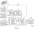
- a plant facilities testing apparatus 100 includes a previous screen data storage device 1, a previous test-item table file storage device 2, a new screen data storage device 3, a new test-item table file storage device 8, a control unit 20, a display device 30, and the like.
- the control unit 20 has a screen difference detection device 4, a test-item table file changing device 5, an addition-portion test-item table file creation device 6, and a test-item table file combining device 7.
- the display device 30 displays a monitoring operation screen for plant facilities installed in a power station.
- the previous screen data storage device 1 stores previous screen information (data) at a time before a design change and a design addition are implemented.
- the previous test-item table file storage device 2 stores a test-item table file at a time before a design change and a design addition are implemented; the test-item table file corresponds to the previous screen information.
- the new screen data storage device 3 stores new screen information (data) at a time after the design change and the design addition have been implemented.
- the screen difference detection device 4 compares the previous screen information obtained from the previous screen data storage device 1 with the new screen information obtained from the new screen data storage device 3 and then extracts the difference between the previous screen information and the new screen information while categorizing the difference into a screen change item and a screen addition item.
- the test-item table file changing device 5 reads and changes the previous test-item table file stored in the previous test-item table file storage device 2.
- the addition-portion test-item table file creation device 6 creates a test-item table file for the addition portion extracted by the screen difference detection device 4.
- the test-item table file combining device 7 combines the test-item table files to which the change and the addition have been applied by the test-item table file changing device 5 and the addition-portion test-item table file creation device 6, respectively.
- the new test-item table storage device 8 stores the output of the test-item table file combining device 7.
- the screen difference detection device 4 extracts a change portion and an addition portion, and a test-item table file for the change portion and a test-item table file for the addition portion are separately created by the test-item table file changing device 5 and the addition-portion test-item table file creation device 6, respectively; therefore, a new test-item table file can efficiently be created.
- Previous screen information at a time before a design change and a design addition are implemented is stored in the previous screen data storage device 1.
- Previous test-item table file at a time before a design change and a design addition are implemented is stored in the previous test-item table file storage device 2.
- New screen information at a time after a design change and a design addition have been implemented is stored in the new screen data storage device 3.
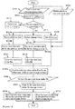
- the screen difference detection device 4 obtains the previous screen information and the new screen information from the previous screen data storage device 1 and the new screen data storage device 3, respectively (step ST01).
- the test-item table file changing device 5 obtains the previous test-item table file from the previous test-item table file storage device 2 (step ST02).
- the screen difference detection device 4 compares the obtained previous screen information with the obtained new screen information and then extracts a change item (or change portion) and an addition item (or addition portion) of the monitoring operation screen (step ST03).
- the addition-portion test-item table file creation device 6 When detecting the addition item extracted by the screen difference detection device 4 (step ST04a), the addition-portion test-item table file creation device 6 creates a test-item table file for the addition portion (step ST04b).
- the test-item table file changing device 5 When detecting the change item extracted by the screen difference detection device 4 (step ST05a), the test-item table file changing device 5 reads and changes the previous test-item table file stored in the previous test-item table file storage device 2 and then creates a test-item table file for the change portion (step ST05b).
- the test-item table file combining device 7 combines the test-item table file created by the test-item table file changing device 5 with the test-item table file created by the addition-portion test-item table file creation device 6 so as to create a new test-item table file (step ST06a), and then outputs the created new test-item table file (step ST06b).
- the new test-item table file storage device 8 stores the new test-item table file output by the test-item table file combining device 7 (step ST07).
- test-item table file changing device 5 transfers the previous test-item table file to the next step (step ST08).
- step ST06a the test-item table file combining device 7 outputs the previous test-item table file as a new test-item table file (step ST06b).
- the screen difference detection device 4 extracts a change portion and an addition portion, and a test-item table file for the change portion and a test-item table file for the addition portion are separately created by the test-item table file changing device 5 and the addition-portion test-item table file creation device 6, respectively; therefore, a new test-item table file can efficiently be created.
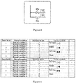
- FIG. 3 illustrates an example of monitoring operation screen, obtained by extracting part of a not updated monitoring operation screen displayed on the display device 30.
- the monitoring operation screen displaying a pipe portion
- two main steam valves are drawn.
- the opening/closing state of a main steam valve 20a is managed with a screen number 104.
- the opening/closing state of a main steam valve 20b is managed with a screen number 105.
- the not updated screen information including, for example, information items on input signals and the display positions of inspection products displayed on this screen is stored in the previous screen data storage device 1.
- FIG. 4 represents a test-item table file corresponding to the monitoring operation screen illustrated in FIG. 3 .
- this test-item table file each of signal numbers 1 through 4 and a setting value (1 or 0) are combined so that the opening/closing states of the two main steam valves are expressed.
- the opening/closing state of the main steam valve 20a is controlled by the respective magnitudes of the setting values designated as the signal numbers 1 and 2.
- the opening/closing state of the main steam valve 20b is controlled by the respective magnitudes of the setting values designated as the signal numbers 3 and 4.
- the setting values (1, 0) suggest that the main steam valve is fully opened.
- the setting values (1, 1) suggest that the main steam valve is half opened.
- the setting values (0, 1) suggest that the main steam valve is fully closed.
- the setting values (0, 0) suggest that the state of the main steam valve is blank.
- FIG. 4 corresponds to a previous test-item table file.
- FIG. 5 illustrates an example of monitoring operation screen, obtained by extracting part of a monitoring operation screen at a time after a design change and a design addition have been applied to the pipe portion.
- a main steam valve 20c is added to the monitoring operation screen displaying the pipe portion.
- the main steam valve 20a is replaced by a check valve 20d.
- the state of the added main steam valve 20c is managed with a screen number 106.
- the state of the check valve 20d is managed with the screen number 104.
- the screen information including information items on input signals and the display positions of inspection products displayed on this screen is stored in the new screen data storage device 3.
- FIG. 6 represents a test-item table file corresponding to the change items in the monitoring operation screen illustrated in FIG. 5 .
- this test-item table file each of signal numbers 5 through 6 and a setting value (1 or 0) are combined so that the opening/closing state of the check valve 20d is expressed.
- the setting values (1, 0) suggest that the check valve 20d is fully opened; the setting values (1, 1) suggest that the check valve 20d is half opened; the setting values (0, 1) suggest that the check valve 20d is fully closed.
- the setting values (0, 0) suggest that the state of the check valve 20d is blank.
- the screen difference detection device 4 extracts the difference and the test-item table file changing device 5 creates a test-item table file for the change portion.
- FIG. 7 represents a test-item table file corresponding to the addition items in the monitoring operation screen illustrated in FIG. 5 .
- this test-item table file each of signal numbers 7 through 8 and a setting value (1 or 0) are combined so that the opening/closing state of the main steam valve 20c is expressed.
- the setting values (1, 0) suggest that the main steam valve 20c is fully opened; the setting values (1, 1) suggest that the main steam valve 20c is half opened; the setting values (0, 1) suggest that the main steam valve 20c is fully closed.
- the setting values (0, 0) suggest that the state of the main steam valve 20c is blank.
- the screen difference detection device 4 extracts the difference and the addition-portion test-item table file creation device 6 creates a test-item table file for the addition portion.
- FIG. 8 represents a new test-item table file, in the monitoring operation screen, that is created by adding the design change and the design addition to a previous test-item table file.
- the test-item table file combining device 7 combines FIGS. 4 , 6, and 7 , so that a new test-item table file represented in FIG. 8 is created. This is an updated test-item table file corresponding to FIG. 5 and is stored in the new test-item table file storage device 8.
- the plant facilities testing apparatus 100 makes it possible to efficiently create a test-item table file for a screen with a different assignment number or a screen created by adding information to a previous screen. Moreover, the plant facilities testing apparatus 100 makes it possible to realize maintenance work by a user, which is required in an oversea nuclear power plant, so that a customer can also readily secure the quality that is at a level the same as that of the factory.
- the screen difference detection device 4 extracts portions in a monitoring operation screen, in which a design change and a design addition are implemented and then the change and the addition are performed based on information in the previous test-item table file, so that the creation time is shortened.
- FIG. 9 is a diagram illustrating the configuration of a plant facilities testing apparatus according to Embodiment 2 of the present invention.
- a screen data managing device 12 is added to the plant facilities testing apparatus according to Embodiment 1.
- the flowchart in FIG. 10 represents the creation procedure for a test-item table file.
- steps ST09 and ST10 are added to the flowchart in FIG. 2 .
- test-item table file combining device 7 When a new test-item table file created by the test-item table file combining device 7 is stored in the new test-item table file storage device 8 (step ST07), the test-item table file combining device 7 stores the new test-item table file in the previous test-item table file storage device 2, so that the original previous test-item table file is replaced by the new test-item table file (step ST09).
- the screen data managing device 12 stores, in the previous screen data storage device 1, new screen information including a design change and a design addition set in the new screen data storage device 3; the original previous screen information is replaced by the new screen information (step ST10).
- the foregoing method can omit the time and trouble for inputting data to the previous screen data storage device 1 and the previous test-item table file storage device 2 when a design change or a design addition occurs again in the screen.
- FIG. 11 is a diagram illustrating the configuration of a plant facilities testing apparatus according to Embodiment 3 of the present invention.
- Embodiment 3 there is provided a screen data setting ascertainment device 9 that reads input data from the previous screen data storage device 1 and the new screen data storage device 3; when the respective screen numbers of a new screen and a previous screen (the respective sheet names of the data files) do not coincide with each other, the screen data setting ascertainment device 9 issues an error message.
- This method can prevent a human error that is caused when an input data file is set.
- the flowchart in FIG. 12 represents the creation procedure for a test-item table file.
- the screen data setting ascertainment device 9 determines whether or not the respective screen numbers (the respective sheet names of the data files) of the new screen and the previous screen coincide with each other (step ST11).
- the screen data setting ascertainment device 9 outputs an error message (step ST12).
- the step step ST11 is followed by the next step.
- the plant facilities testing apparatus 100 makes it possible to efficiently create a new test-item table file for a screen with a different assignment number or a screen created by adding information to a previous screen. Moreover, the plant facilities testing apparatus 100 makes it possible to realize maintenance work by a user, which is required in an oversea nuclear power plant, so that a customer can also readily secure the quality that is at a level the same as that of the factory.
- FIG. 13 is a diagram illustrating the configuration of a plant facilities testing apparatus according to Embodiment 4 of the present invention.
- each of the test-item table file changing device 5 and the addition-portion test-item table file creation device 6 has a coloring function. Coloring the item number that has been changed from or added to the previous test-item table file makes it possible to readily detect the change portion and the addition portion. It may be allowed that instead of the coloring function, a light-and-shade display makes it possible to detect a change portion and an addition portion.
- the flowchart in FIG. 14 represents the creation procedure for a test-item table file.
- a test-item table file for the addition portion is created (step ST04b); then, the test-item table file is colored (step ST13).
- the change portion in a test-item table file is changed (step ST05b); then, the test-item table file is colored (step ST14).
- FIG. 15 illustrates an example of monitoring operation screen, obtained by extracting part of a monitoring operation screen at a time after a design change has been applied to the pipe portion.
- FIG. 16 illustrates an example of monitoring operation screen, obtained by extracting part of a monitoring operation screen at a time after a design addition has been applied to the pipe portion.
- left-end four columns are colored (in practice, FIGS. 15 and 16 are not colored but greyed.
- the plant facilities testing apparatus 100 makes it possible to efficiently create a new test-item table file for a screen with a different assignment number or a screen created by adding information to a previous screen. Moreover, the plant facilities testing apparatus 100 makes it possible to realize maintenance work by a user, which is required in an oversea nuclear power plant, so that a customer can also readily secure the quality that is at a level the same as that of the factory.
- FIG. 17 is a diagram illustrating the configuration of a plant facilities testing apparatus according to Embodiment 5 of the present invention.
- the plant facilities testing apparatus 100 according to Embodiment 5 is provided with a test-item table file revision history creation device 10 and a test-item table file revision history storage device 11.
- the test-item table file revision history creation device 10 automatically creates a revision history in which a concerned screen number, a creation date and time, a change portion, an addition portion, and the like are listed and stores the created file in the test-item table file revision history storage device 11.
- the flowchart in FIG. 18 represents the creation procedure for a test-item table file.
- a test-item table file for the addition portion is created (step ST04b); then, the test-item table file revision history (record) for the addition portion is created (step ST15a).
- step ST05a the change portion in a test-item table file is changed (step ST05b); then, the test-item table file revision history for the change portion is created (step ST15a).
- the created test-item table file revision history (revision record) is output (step ST15b) and then is stored in the test-item table file revision history storage device 11 (step ST16).
- the plant facilities testing apparatus 100 makes it possible to efficiently create a new test-item table file for a screen with a different assignment number or a screen created by adding information to a previous screen and to create a test-item table file revision history. Moreover, the plant facilities testing apparatus 100 makes it possible to realize maintenance work by a user, which is required in an oversea nuclear power plant, so that a customer can also readily secure the quality that is at a level the same as that of the factory.
- the present invention relates to an apparatus that automatically creates a test-item table file to be utilized in testing a GUI (Graphic User Interface) control program in a monitoring operation screen for a power station.
- GUI Graphic User Interface
Landscapes
- Engineering & Computer Science (AREA)
- Power Engineering (AREA)
- Human Computer Interaction (AREA)
- Physics & Mathematics (AREA)
- General Physics & Mathematics (AREA)
- Automation & Control Theory (AREA)
- Testing And Monitoring For Control Systems (AREA)
Applications Claiming Priority (1)
| Application Number | Priority Date | Filing Date | Title |
|---|---|---|---|
| PCT/JP2013/068980 WO2015004771A1 (fr) | 2013-07-11 | 2013-07-11 | Dispositif de test d'équipement d'usine |
Publications (2)
| Publication Number | Publication Date |
|---|---|
| EP3021186A1 true EP3021186A1 (fr) | 2016-05-18 |
| EP3021186A4 EP3021186A4 (fr) | 2017-05-03 |
Family
ID=52279493
Family Applications (1)
| Application Number | Title | Priority Date | Filing Date |
|---|---|---|---|
| EP13889345.8A Withdrawn EP3021186A4 (fr) | 2013-07-11 | 2013-07-11 | Dispositif de test d'équipement d'usine |
Country Status (4)
| Country | Link |
|---|---|
| US (1) | US10090705B2 (fr) |
| EP (1) | EP3021186A4 (fr) |
| JP (1) | JP5936775B2 (fr) |
| WO (1) | WO2015004771A1 (fr) |
Cited By (1)
| Publication number | Priority date | Publication date | Assignee | Title |
|---|---|---|---|---|
| CN109299008A (zh) * | 2018-09-21 | 2019-02-01 | 北京广利核系统工程有限公司 | 一种核电站控制系统安全功能自动测试系统及方法 |
Family Cites Families (20)
| Publication number | Priority date | Publication date | Assignee | Title |
|---|---|---|---|---|
| JPH09330248A (ja) | 1996-06-12 | 1997-12-22 | Hitachi Ltd | Gui制御プログラムのイベントテスト方式 |
| DE19732046A1 (de) * | 1997-07-25 | 1999-01-28 | Abb Patent Gmbh | Prozeßdiagnosesystem und Verfahren zur Diagnose von Vorgängen und Zuständen eines technischen Prozesses |
| JPH11175370A (ja) | 1997-12-10 | 1999-07-02 | Hitachi Ltd | プログラムテスト方法 |
| US6167401A (en) * | 1998-02-09 | 2000-12-26 | Ciena Corporation | Manufacturing control network having a relational database |
| US7089256B2 (en) * | 2000-07-11 | 2006-08-08 | Knowledge Dynamics, Inc. | Universal data editor |
| JP3689767B2 (ja) * | 2000-09-22 | 2005-08-31 | 株式会社日立製作所 | 火力発電プラント保守サービス提供方法 |
| FI113302B (fi) * | 2001-05-25 | 2004-03-31 | Metso Automation Oy | Tilannekuvien käyttäminen teollisuusautomaatioprosessin ohjausjärjestelmässä |
| JP2003141282A (ja) * | 2001-11-05 | 2003-05-16 | Hitachi Ltd | 検査日程管理支援システムおよび検査日程管理支援方法 |
| US7464067B2 (en) * | 2002-04-10 | 2008-12-09 | Hotbutton Solutions Inc. | Object monitoring and management system |
| JP4619995B2 (ja) | 2006-06-16 | 2011-01-26 | 株式会社東芝 | プラント監視装置及びプラント監視システム |
| US8359248B2 (en) * | 2006-08-24 | 2013-01-22 | Blue Pillar, Inc. | Systems, methods, and devices for managing emergency power supply systems |
| JP4573844B2 (ja) | 2007-01-19 | 2010-11-04 | 中国電力株式会社 | 監視制御装置用画面保守支援装置および監視制御装置の画面保守方法 |
| US20080310736A1 (en) * | 2007-06-15 | 2008-12-18 | Microsoft Corporation | Smart visual comparison of graphical user interfaces |
| CN102105843B (zh) * | 2008-08-06 | 2013-12-18 | 三菱电机株式会社 | 工厂监视控制系统 |
| KR100982774B1 (ko) * | 2008-09-30 | 2010-09-16 | 한국전력기술 주식회사 | 원자력발전소 제어계통 성능검증 장치 및 방법 |
| US8117218B2 (en) * | 2008-11-24 | 2012-02-14 | The Boeing Company | Methods and systems for automated data mapping and analysis |
| US9043003B2 (en) * | 2009-07-31 | 2015-05-26 | Fisher-Rosemount Systems, Inc. | Graphical view sidebar for a process control system |
| JP5489958B2 (ja) | 2010-11-25 | 2014-05-14 | 三菱電機株式会社 | 試験テーブル生成装置及びその方法 |
| JP5628086B2 (ja) * | 2011-04-22 | 2014-11-19 | 株式会社日立製作所 | 表示装置画面の全点試験方法及び全点試験装置 |
| JP5777492B2 (ja) | 2011-11-02 | 2015-09-09 | 三菱電機株式会社 | 監視操作画面試験支援装置 |
-
2013
- 2013-07-11 EP EP13889345.8A patent/EP3021186A4/fr not_active Withdrawn
- 2013-07-11 WO PCT/JP2013/068980 patent/WO2015004771A1/fr not_active Ceased
- 2013-07-11 JP JP2015526093A patent/JP5936775B2/ja not_active Expired - Fee Related
- 2013-07-11 US US14/784,777 patent/US10090705B2/en active Active
Cited By (2)
| Publication number | Priority date | Publication date | Assignee | Title |
|---|---|---|---|---|
| CN109299008A (zh) * | 2018-09-21 | 2019-02-01 | 北京广利核系统工程有限公司 | 一种核电站控制系统安全功能自动测试系统及方法 |
| CN109299008B (zh) * | 2018-09-21 | 2021-11-30 | 北京广利核系统工程有限公司 | 一种核电站控制系统安全功能自动测试系统及方法 |
Also Published As
| Publication number | Publication date |
|---|---|
| US10090705B2 (en) | 2018-10-02 |
| JP5936775B2 (ja) | 2016-06-22 |
| US20160079808A1 (en) | 2016-03-17 |
| EP3021186A4 (fr) | 2017-05-03 |
| JPWO2015004771A1 (ja) | 2017-02-23 |
| WO2015004771A1 (fr) | 2015-01-15 |
Similar Documents
| Publication | Publication Date | Title |
|---|---|---|
| JP6052265B2 (ja) | I/oモジュール、設定装置、及びプロセス制御システムの構築方法 | |
| EP3296830B1 (fr) | Appareil d'affichage d'état d'installation, système d'affichage d'état d'installation et procédé d'affichage d'état d'installation | |
| Landucci et al. | A methodology for frequency tailorization dedicated to the Oil & Gas sector | |
| EP2881815A2 (fr) | Appareil de gestion de dispositif de champ, procédé d'affichage d'informations de dispositif, support de stockage lisible par ordinateur | |
| TWI735844B (zh) | 異常監視裝置及異常監視方法 | |
| WO2008012164A1 (fr) | Procédé pour déconnecter des fonctionnalités particulières dans des appareils de terrain en technique d'automatisation | |
| US10691118B2 (en) | Information retrieval system and method | |
| Baglietto et al. | Mode-observability degree in discrete-time switching linear systems | |
| CN106194698B (zh) | 压缩机试车台控制系统和控制方法 | |
| EP3021186A1 (fr) | Dispositif de test d'équipement d'usine | |
| US20120290969A1 (en) | Multi-stage method and apparatus for interactively locating device data of an automation system | |
| JP2014032633A (ja) | プラント監視装置およびプラント操作方法 | |
| JP6249080B2 (ja) | 設定装置、i/oモジュール、及びプロセス制御システムの構築方法 | |
| CN101727082B (zh) | 一种操作画面单一位置显示多项报警信息的方法 | |
| B Ahmad et al. | Samarang Integrated Operations (IO): Well performance workflows enable continuous well status and performance monitoring | |
| JP6388487B2 (ja) | 保全評価システム | |
| US8930000B2 (en) | Plant monitor and control device and a maintenance support method thereof | |
| KR101740666B1 (ko) | 사이버 보안 평가 관리 시스템의 동작방법 | |
| JP4607702B2 (ja) | プラント運転支援装置およびプラント運転支援方法 | |
| US20220147906A1 (en) | Work schedule creation system and work schedule creation method | |
| Günther et al. | Fault detection data creation using an experimental water distribution system | |
| CN106468374A (zh) | 用于阀设置的系统 | |
| JP2005190196A (ja) | 巡視点検支援方法、巡視点検支援装置 | |
| JP6516419B2 (ja) | プラント制御システム | |
| JP6854698B2 (ja) | 模擬信号試験装置 |
Legal Events
| Date | Code | Title | Description |
|---|---|---|---|
| PUAI | Public reference made under article 153(3) epc to a published international application that has entered the european phase |
Free format text: ORIGINAL CODE: 0009012 |
|
| 17P | Request for examination filed |
Effective date: 20151231 |
|
| AK | Designated contracting states |
Kind code of ref document: A1 Designated state(s): AL AT BE BG CH CY CZ DE DK EE ES FI FR GB GR HR HU IE IS IT LI LT LU LV MC MK MT NL NO PL PT RO RS SE SI SK SM TR |
|
| AX | Request for extension of the european patent |
Extension state: BA ME |
|
| DAX | Request for extension of the european patent (deleted) | ||
| A4 | Supplementary search report drawn up and despatched |
Effective date: 20170331 |
|
| RIC1 | Information provided on ipc code assigned before grant |
Ipc: G05B 23/02 20060101AFI20170327BHEP Ipc: H02J 13/00 20060101ALI20170327BHEP |
|
| GRAP | Despatch of communication of intention to grant a patent |
Free format text: ORIGINAL CODE: EPIDOSNIGR1 |
|
| INTG | Intention to grant announced |
Effective date: 20171222 |
|
| STAA | Information on the status of an ep patent application or granted ep patent |
Free format text: STATUS: THE APPLICATION HAS BEEN WITHDRAWN |
|
| 18W | Application withdrawn |
Effective date: 20180305 |